1. Introduction
The use of multi-agent systems (MASs) has increased in industrial and academic applications due to their capacity to deal with physically or logically distributed problems. MASs solve complex problems with entities called
agents, using their collaborative and autonomous properties [
1]. They have been developed for a wide range of applications, including diagnostics, condition monitoring, power systems restoration, market simulation, network control, automation, logistics, manufacturing, operational research and management science, sociotechnical studies, industrial engineering, technological innovation, control engineering, and workflow systems [
2]. Moreover, they set singular characteristics that pertain to agents such as reactivity, proactivity, autonomy, and social capacity [
3].
However, a MAS still demands reliable tools for verification activities, including testing procedures. Testing MASs is not a trivial task. It deals with systems that have properties such as autonomy and are deliberative in an open world, which makes them sensitive to the context [
4]. Some applications, especially those with real-time constraints and more critical requisites, require some level of guarantee about their risks. They include modern applications such as cyberphysical systems integrated with digital twins for controlled objects [
5].
A constant criticism when using MAS approaches is the lack of determinism on a large scale. For example, a recent analysis of COVID-19 pandemic models highlights a lack of transparency, reproducibility, and an urgent need for more rigorous validation, especially those based on MAS models [
6,
7].
Testing is just one activity of a complete verification and validation framework. It provides a way to assess the likelihood that software will fail during use and is broadly divided into dynamic software testing and formal verification [
8]. Nevertheless, some works propose combining these techniques, formal methods, simulation, and experiments, increasing the coverability, i.e., exploring the state space of MAS solutions [
9,
10]. In addition, MASs is a very broad research topic, including machine learning and other non-symbolic issues, and testing those approaches is entirely different from testing symbolic approaches. This topic is inside a broad area named engineering multi-agent systems, which covers subtopics such as agent systems verification [
11], requirements engineering for developing MASs [
12], and testing for MASs [
13], the latter one more closely related with this work.
The MAS social level has, formally or informally, an underlying organizational model. Organizational frameworks can reduce the amount of interaction between agents, reduce or explicitly increase system redundancy, and formalize high-level system goals. A single agent cannot be aware of all social knowledge [
14]. An organization establishes a set of behavioral constraints that a group of agents employs to control agent autonomy and achieve their goals efficiently [
15].
With an organizational modeling language that explicitly decomposes a specification into structural, functional, and deontic dimensions, the
oise+ is one of the most referenced organizational models. Organizations are described using notions such as
roles,
groups, and
links in the structural dimension. A system is described by global collective goals that must be achieved in the functional dimension. Finally, the deontic dimension binds the structural and functional aspects together, defining
permissions for each role and mission
obligations [
16]. Usually, an MAS based on a
oise+ organization is implemented with Jason, an agent platform based on an extension of an agent-oriented programming language called AgentSpeak(L) [
17].
High-level Petri nets are a widely used modeling, specification, and validation tool for information system behavior in general. Combining a simple graphical notation with a mathematical foundation is their differential when compared with correlate techniques. They permit an integrated scheme of data structures, and the modeled behavior [
18]. When used for testing, a Petri net consists of input conditions (causes) and a description of the expected output conditions (effects) achieved by its execution under the defined input conditions. Colored Petri nets (CPNs) [
19] are a class of high-level Petri nets offering these features and naturally representing the distributed features of an MAS [
20]. When compared with finite state machine (FSM) methods, a CPN requires lower computational costs, and the length of the test suites can be reduced by using the equivalent space-state [
21].
In this paper, we present a method for testing MAS social level specified by oise+ organizational model. The proposed method takes the tree specifications that compose a oise+ model as an information artifact and maps them into a colored Petri net specific model, named CPN4M. This model is used as a generation mechanism for test cases. It can generate a test suit based on two coverage criteria. The all paths method identifies all different paths inside a Petri net structure to generate the test cases. Meanwhile, the states transition path method assesses the specification testability and generates the test cases based on CPN state space.
Applying these methods in a study case, we demonstrate that the all-paths strategy can quickly deliver test cases based on the social level inputs. On the other hand, the state transition path strategy can generate states’ space more significant than the previous method, but not necessarily the same space of solutions. The case study also demonstrates how to identify an error in a oise+ specification and how to correct it. Finally, the results indicate that the proposed method can mitigate the absence of a formal integration verification between the three specifications of a oise+ model. It identifies when a social level specification has a complete biding between its resources to execute its plans and reach its goals.
The list of paper contributions are summarized as follows:
A strategy for testing a MAS, modularizing its three main components: social level, communication aspects, and the agent level.
An approach for testing the MAS social level when implemented with the oise+ organizational model.
A formal mapping between a oise+ specification and CPN structures and data structure.
The use of CPN analysis and validation tools as verification mechanism for oise+ specifications.
The paper has the following structure. The next section presents the theoretical background necessary to understand the paper’s contribution. Then,
Section 4 formalizes the method, the procedures for testability assessment, and test cases generation. Next,
Section 5 describes a case study where it is possible to evaluate the method, demonstrating how to generate a test case for each coverage criteria, how to identify errors and correct them, and how to recognize a correct specification. Finally,
Section 6 presents the conclusions of this work and its perspectives for future works.
2. Background
This section gives the reader the theoretical background necessary to understand this work entirely. It covers three main topics: (i) the basic concepts of testing and test case generation in the context of MASs; (ii) the oise+ organizational model, which comprehends part of the problem definition, and; (iii) colored Petri nets, which is used as part of the solution in this work.
Multi-agent systems are composed of multiple interacting computing elements, known as agents. Agents are computer systems with two essential capabilities: (i) they can make autonomous actions, and (ii) they are capable of interacting with other agents [
22]. Any MAS architecture has components distributed between three levels: (i) the individual level, where the agents are specified and implemented; (ii) the interaction aspects, where formalized communication protocols are specified; (iii) and the social level, that can be realized in an explicit formalization or can be emerged by non-controlled coordination between the system entities, i.e., the agents themselves [
23].
The individual level can be solved by BDI architectures, using, for example, programming languages such as Jason and JADE [
24]. When in the validation phase by testing procedures, this level corresponds to those indicated by Nguyen et al. [
25], such as unit and agent abstractions.
The interaction aspects cover issues related to communication protocols, such as FIPA [
26] and MQTT, yet specified by UML or AUML [
27]. In the Nguyen et al. [
25] view, this development step is validated in the integration test abstraction.
The social level makes collective intentionality feasible when it defines how to coordinate individual actions in global goals. There are two ways to realize this intentionality: (i) it emerges by arising in novel and coherent structures, patterns, and properties during the process of self-organization in complex systems [
28]; (ii) it is formally specified by an organizational model. At the testing phase, this level corresponds to the society abstraction defined by Nguyen et al. [
25].
The social level covers the testing scope proposed in this work. For the individual level, the work proposed by Winikoff [
29] solves the testability for BDI systems. On the other hand, agent interaction protocols (AIP) is a conformance testing technique for agent interaction protocols, using aspect-oriented technology to support and monitor the testing process [
30].
In the testing process proposed here, an organizational model specifies the social level, more specifically, oise. When executing an MAS, this specification is instantiated by agents once they share social concepts such as goals, plans, groups, and roles. First, however, these social specifications must be assessed on their correctness, which means to evaluate if the resources allocated by plans, groups, and roles are necessary and sufficient to reach the MAS goals.
On the other hand, Petri nets are a well-known formal method for verification tasks on concurrent systems, such as multi-agent systems. This work adopts a high-level model of Petri nets, colored Petri nets, as a path-traversal generation mechanism since it explores the different possible paths through a transverse representation of the system-under-test. The different paths through the system correspond to different possible executions and test cases.
2.1. Testing and Test Case Generation
A testing procedure tries to locate errors in the code or specification. In this sense, errors can lead to failures in the system execution, deviating between the actual and expected outcomes.
For software, a testing method generally relies on four main components: an information artifact, a generation mechanism, test data adequacy criteria, and a test oracle.
Figure 1 sketches this process.
The definitions of these components alongside fundamental testing concepts used on the paper are as follows [
13]:
Test: The act of exercising software with test cases to find faults or demonstrate correctness.
Test case: A set of inputs, preconditions, and expected outcomes associated with a particular program behavior.
Test suite: A collection of test cases.
Test execution: An execution of the system-under-test constrained to the conditions specified by a given test case.
Information artifact: A source of information used as a guide for generating test cases. It can be a formal specification, a design document, or source code, and provides information about the system’s functionality or goals necessary to produce meaningful test cases.
Generation mechanism: An algorithm or strategy adopted to generate a test case from an information artifact.
Test data adequacy criterion: A measure of test case quality concerning a testing goal such as coverage. A test data adequacy criterion is often used to guide test case generation towards achieving the defined goal.
Coverage criteria: It is a measure of test adequacy focusing on how thoroughly a test suite covers a specified portion of the information artifact that represents some functionality in the system-under-test.
Test oracle: A procedure to evaluate if given a test execution is correct or not. It may be specified, derived, implicit, or human.
2.2. oise
The organizational model
oise
was initially proposed in Hannoun et al. [
31] and has been improved over time. It includes a language for MAS organization and infrastructure specification, supporting organization-based reasoning mechanisms at the agent level. Usually, we write the specification via an XML file containing three different specifications: structural specification (SS), functional specification (FS), and deontic specification (DE) [
32].
The structure of the
oise
model also has the individual, social, and collective levels of the previous version, but the descriptions of these levels are slightly different. A role is a link between the agent and the organization at the individual level. At the social level, roles are related to other roles, representing restrictions imposed on a role’s interactions with others. Finally, at the collective level, the group represents a group of agents with more significant affinities and closer objectives [
33].
Figure 2 shows an example of an SS, which consists of two roles
roleA and
roleB that are sub-roles of
roleC. The connection links can represent acquaintance, communication, authority, and compatibility.
The FS in oise is made up of a set of social schemes and a mission preference relationship. Social schemes are based on a global goal, representing a state of the world desired by a multi-agent system. On the other hand, the local goal is a single agent’s goal. The FS has two levels: (i) the individual level, where the social scheme is made up of missions, and (ii) the collective level, where the social scheme itself is a tree of global goals decomposition. The root is the social scheme’s goal, and the decomposition of the goals is carried out through plans.
Figure 3 presents a goal decomposition tree of a social scheme. Reading should be performed from left to right and from bottom to top. For example, in this scheme, an agent who takes on the
m1 mission must commit to the goal
g5, then another agent with the mission
m2 performs
g5, which will make
g2 be automatically performed. In this example, there are three types of operators used to build a plan:
Sequence : The plan means that the goal will be achieved if the goals and are achieved in that order.
Choice : The plan means that the goal will be achieved if one, and only one, of the goals or is achieved.
Parallelism : The plan means that the goal will be achieved if both and are achieved in parallel.
The deontic specification (DS) describes the roles’ permissions and obligations for missions. A
permission(p,m) states that an agent playing the role
p is allowed to commit to the mission
m. Furthermore, an
obligation(p,m) states that an agent playing
p ought to commit to
m. For example a DS is shown in
Table 1, where we can say that the role
roleA is allowed to perform the
mission, so any agent with the role
roleA can achieve a goal that is related to
.
A social description of oise is the integration of three specifications, ES, FS, and DS. However, no formal mechanism or procedure evaluates if the integration is correct. The correctness about global goals defined has the necessary resources (plans, roles, missions, and deontic relations) to be feasible in the environment when executed. For example, without a formal evaluation, roles can be assigned to missions that cannot execute the attributed plan. Alternatively, a deontic relation can be established between role and mission without guaranteeing the plan’s executability. In this sense, it is necessary to define procedures to evaluate if a oise specification is feasible when instantiated by the agents in the system.
2.3. Colored Petri Net
A colored Petri net (CPN) is a graphical and mathematical modeling language for building concurrent systems models and analyzing their properties. There are two classes of Petri nets: low-level and high-level. CPN belongs to a high-level class, as they combine an ordinary PN’s capabilities with features of a programming language.
In the CPN, the tokens have a data value attached, which are called colors. These colors can represent different processes or resources of a net, thus reducing the model’s size compared with low-level models. Furthermore, all cards must have colors belonging to a specific type for a given place, called the set of colors. This use of color sets is equivalent to data types in programming languages (integer, character, Boolean), and the specification of color sets and network variables is made by declarations.
CPN composition contains a structure, inscriptions, and declarations. It is a directed graph with two types of vertices: (i) circles or ellipses represent the places, and (ii) the transitions by rectangles. Each place, transition, and arc of the network has associated inscriptions. For example, places have three types of inscriptions: names, color set, and initialization expression, which is the initial mark. The declarations are the specifications of the color sets and the declaration of the variables.
To illustrate all these elements,
Figure 4 is a CPN representation of the dining philosophers, a classic synchronization problem in computer science, which is used to evaluate situations where there is a need to allocate multiple resources to multiple processes. In this example, there are three places, named
,
, and
; two transitions,
and
; the colors (or tokens)
and
, with respective color set
and
; the variable
p, and a arc function named
. This example was generated using the CPN modeling tool called
(
http://cpnTools.org, accessed on 9 May 2022).
The different markings that a CPN can achieve are called state space. Jensen and Kristensen [
35] defined a
state space as a directed graph in which there is a node for each accessible mark and an arc for each connecting element that occurs. They also claim that a state space represents all possible executions of the system under consideration and can verify that the system has a particular formally specified property.
The hypothesis of this work proposes CPN as the test case generation mechanism for the society abstraction level of an MAS, and the information artifact is the oise+ specification. Different paths inside the CPN model represent the expected social behavior. Each path corresponds to an execution of the system-under-test, and the corresponding reachability graph indicates the set of test cases necessary to validate it.
3. Related Works
There are some works that treat the aspects of test in agents. However, we did not find works related to organizational tests to agents.
Bakar and Selamat [
11] investigated testing techniques for agent systems in general, mapping the different properties and faults that existing techniques may detect. They revealed plenty of techniques for functional requirements, while there are fewer techniques that target non-functional requirements.
Blanes et al. [
12] covered different aspects of requirements engineering, including specification and validation. They concluded that ontologies are the most used technique to deal with requirements and identified that roughly a quarter of the literature provided some form of automated validation, which indicates the necessity for automatic approaches to test agent-based models.
According to Nguyen et al. [
25], there are five levels of abstraction in MAS testing: (i)
unity: testing codes and modules unity that comprise agents such as plans, goals, sensors, reasoning mechanisms, and others; (ii)
agent: testing the various modules of an agent, as well as the agent’s resources in order to reach its goals and to detect the environment; (iii)
integration: evaluating the agent’s interaction communication protocols and semantics, as well as the environment and shared resources; (iv)
society: putting the entire MAS to the test in a fateful operational context, looking for quality qualities including adaptability, openness, failure tolerance, and performance; (v)
acceptance: the MAS is tested in its execution environment to see if it meets the system’s objectives.
A specific approach for testing MASs on embedded systems is provided in Barnier et al. [
36], and it is built on three basic levels: agent test, collective resources test, and acceptance test. Defining the goals for a well-succeeded test for each level is necessary.
At the agent level, Winikoff [
29] proposed a method for testability assessment on BDI (
belief–desire–intention) agents, where two different adequacy criteria were compared: the
all edges, which is satisfied if the set of tests covers all edges in a control-flow graph; and the
all paths criterion, where a test set is adequate if the test cover all paths in the control-flow graph of the program. The degree of testability obtained is used to indicate the number of test cases needed to validate a BDI program.
Additionally at the agent level, do Nascimento et al. [
37] proposed a signature-based architecture that simplifies the MAS project, which includes a test integration level. Finally, in Kerraoui et al. [
38], they explored the Petri nets representation power with an approach covering the agent, integration, and system levels with functional tests. Using behavioral system models as inputs automatically generates test cases. When investigating the literature on this topic, we must be careful regarding a similar area that approaches the use of agents for automating software testing. For example, in Kumaresen et al. [
39], this research area is defined as agent-based software testing (ABST). However, in this case, agent methodologies, architectures, and tools are employed to improve different test problems. ABST investigates the use of agents for testing rather than how to test agents.
In Clark et al. [
13], the authors presented a systematic review of test case generation for agent-based models. Considering the five levels of abstraction proposed by Nguyen et al. [
25], the authors concluded that the majority of techniques for testing are adequate for functional requirements and the agent and integration levels, and there are comparatively few techniques capable of testing society-level behavior. For that reason, the authors indicated the need for test case generation techniques that focus on societal and non-functional behavior.
4. Testing oise Using Different Test Adequacy Criterion
This section will present a method for testing MASs under the oise organizational model. The method uses its three specification types (FS, SS, and DS) as information artifact, a CPN model as the generation mechanism for the test case generation, and a test suite with two coverage criteria: all paths and state transition path. In the all paths criteria, the number of execution paths mapped inside a CPN is calculated and used as the reference to assess its testability. The second criteria, called state transition path, is based on the sum of the paths in the CPN state spaces, i.e., its reachability graph.
We offer a test approach based on a perspective in which an MAS is seen from three dimensions in a global view of its development [
23]: (i) an
organization, corresponding to the social level, in which the elements that allow for agent interaction and coordination between agents are formally or informally structured; (ii) the
communication level concerned with issues such as protocols and information exchanges between agents; and, finally, (iii) the
agents level relates to the individual level specification, where the organization’s requests are instantiated based on each agent’s individual capacities and skills. In this context, this article focuses on tests related to the organization of a multi-agent system in this context.
Recovering the context presented in the Introduction, in an MAS, an organization is a set of roles, relationships, and authority structures that regulate behaviors. Even if it exists just implicitly and informally or through formal organizational models, the organization exists. These rules have an impact on data flow, resource allocation, coordination standards, authority relationships, and other aspects of the system [
40].
oise
is one of the most referenced organizational models. It considers an MAS to be an organization or a set of normative rules that limit the agent’s actions. Three fundamental concepts represent these organizational restrictions: roles, plans, and norms [
31]. It has three levels of structure (individual, collective, and social) and three forms of specification (structural, functional, and deontic). Each agent’s available behaviors are constrained at the individual level. The number of agents who can cooperate is limited at the collective level. Finally, the social level limits the kind of interactions that the agents can perform.
The following are the reasons for using Petri nets to map an MAS [
41]: (i) they give a graphical and mathematically based modeling framework, which is a must for system development procedures that require both graphical and algorithmic tools; (ii) as a result of the
oise
specification’s abstraction and hierarchical refinement processes, they can incorporate the different levels and types of the specification; (iii) there are numerous algorithms for the creation and analysis of Petri nets, as well as powerful tools to assist in these processes; (iv) Petri net models come in a variety of models, but they are all linked by the basic formalism on which they are based. Furthermore, extensions such as timed, stochastic, high-level, and others, and the base model, the ordinary Petri net, fulfill the unique needs of practically every application field.
However, once several dimensions of representation, defined by a structural specification (SS), a functional specification (FS), and a deontic specification (DS), are integrated, the standard Petri net model is insufficient to represent a comprehensive
oise
model [
31]. Therefore, our approach contains a mapping procedure that uses a model based on colored Petri nets [
19] since it requires a more powerful representation resource.
In our method, colored tokens are labels used to represent the organization’s roles and groups. First, the places are associated with the tokens’ color set, which means places are the goals. Then each place will have the color associated with the set of related roles and groups. According to the deontic specification, it is possible to correlate with the mission that represents that place. The arcs that connect the places to the transitions now receive a variable, or an arc expression, with value belonging to the role, describing which token is leaving the X place and going to the Y place.
Considering
Figure 1, the proposed testing method can be described by:
System-under-test: It is a oise specification which describes the social behavior of an MAS.
Information artifacts: The oise specification is composed of three information artifacts that must be integrated: the functional specification (FS), structural specification (SS), and deontic specification (DS). The leading cause for fails in a oise specification is the absence of formal integration between those specifications.
Generation mechanism: For the test case generation mechanism, the CPN model is proposed, to be formally described in the following lines. The proposed model can integrate the three specifications of oise model.
Test suite: It is generated based on two coverage criteria: all paths, where each case test corresponds an execution path inside the CPN model, and state transition path, where each case test generated corresponds to a state inside the CPN reachability graph, to know, its space state.
Test oracle: It is the execution of the CPN model covering all paths of its model and reachability graph, evaluating if in the execution possibilities it is possible to reach the final place and state, which corresponds to the root goal of oise specification, without using a fail path.
Definition 1. A Colored Petri Net for oise () is a nine-tuple:where R is a finite set of constants with dimension j which represent roles in a oise organization.
is a finite set of constants with dimension k which represent groups in a oise organization.
P is a finite set of places with dimension n which represent goals in a oise organization.
T is a finite set of transitions with dimension m which define plans to achieve the goals in an organization.
A is a set of arcs and .
Σ is a non-empty finite color set which represents roles and groups in an oise organization.
V is a set of typed variables such that for all variables , which define the deontic specification in a oise organization.
is a set of colors functions, which assigns color sets to places, defining which roles and groups are responsible by which goals in a oise organization.
is a guard function which assigns a guard to each transition t such that .
is an arc expression function that assigns an arc expression to each arc a such that , where p is the place connected to the arc a.
is an initialization function which assigns an initialization expression to each place p such that , defining an order of execution for goals in a oise organization.
Figure 5 depicts an overview of the phases in the testing methodology model proposed in this work, and it is instantiated in
Figure 1. The first step is to examine a
oise
specification, mapping it in a
specification, in the second step. The net mapping consists of the following steps: (i) generate declarations, (ii) model the structure, (iii) include inscriptions, (iv) include failure transitions. With the
generated, the third step consists of counting the network’s test cases, thus ending the testability part of
oise
specification. The fourth and last step is the generation of test cases based on the paths discovered, using them to run tests on the system. For now, we do not develop an automatic tool utilizing this methodology. The procedures and declarations presented in the following steps are executed manually.
4.1. Mapping oise to Colored Petri Net—
The method’s first step is mapping a
oise
specification in a
.
Figure 5 describes the mapping steps, consisting of the following:
4.1.1. Generating Declarations
The declarations are based on the structural specification (SS). For each role and group of the SS, a specific color must be created.
Definition 2 (Generating Declarations).
where is a role in an organizational model; is a group in an organizational model; is a color of the CPN; is a variable related to a color in the CPN. For example, a generic declaration for the colors roleA, roleB, and roleC that belong to the color set R, a generic declaration for the groups groupA and groupB that belong to the color set G, followed by three variables p, p1, and p2, with reference to the product of R*G named RG.
colset R = with roleA | roleB | roleC ;
colset G = with groupA |groupB;
colset RG = product R*G;
var p,p1,p2 : RG;
4.1.2. Modeling the Structure
The
structure modeling is based on the functional specification (FS) of the
oise
model. Using the list of operators described in
Figure 6, it is possible to transform each plan operator (sequence, choice, and parallelism) of an FS into a corresponding
structure.
Definition 3 (Modeling Sequential Structure).
where is each defined plan in organizational model; is a place of the CPN; is an arc of the CPN; is a goal in oise. Definition 4 (Modeling Choice Structure).
where is each defined plan in an organizational model; are possible places of the CPN; are possible arcs of the CPN; are goals in oise. Definition 5 (Modeling Parallel Structure).
where is each defined plan in an organizational model; are possible places of the CPN; are possible arcs of the CPN; are goals in oise. 4.1.3. Including Inscriptions
The deontic specification (DS) is included as inscriptions, which follows the assignment of roles and groups to each mission, which defines which colors should be assigned to each place in the net. The same logic must define arc transitions and inscriptions, including the initialization function (the initial inscription).
Definition 6 (Including Inscriptions).
where is each defined arc of the CPN; is a guard function of the CPN; is arc expression function of the CPN; is the initial goal in oise; is an initialization function of the CPN; In
Figure 7, these inscriptions are in a choice example. There are three colors (or tokens) named
,
, and
; two groups,
and
; two variables,
p and
b; five places:
,
,
,
, and the final place
; five transitions:
,
,
,
, and
; and three arc functions:
,
, and
. Some transitions have a guard function, such as
in
and
, or
in
, or
in
.
An observation about the place: it represents an initial state in which the system is on standby waiting to start and is not part of the oise specification. This starting place, as well as places that represent goals that do not have a linked mission and therefore do not need a role that satisfies them, depending only on the completion of other goals to fulfill them, receive the color type , which represents the Boolean type that accepts two types of tokens: and .
4.1.4. Failure Transitions
The last part of the network mapping is the inclusion of transitions activated in case of an error during a goal’s execution. A goal can fail because an agent cannot complete its plan actions and display an error message. As mentioned in Winikoff [
29], on an MAS, there is a possibility of failure to execute a plan due to environmental interference. In the CPN4M, an error can be identified once the execution follows a path to the
Fail place or it has generated conditions for a deadlock. To summarize, only places that are not
and have an obligation type in DS can receive a failure path.
Definition 7 (Failure Transitions).
where is each transition of the CPN; is the arc expression function of the CPN that represents the error of the transition; is the goal of the CPN that represents the fail. For the previously presented example, we now have included a failure path (
Figure 8), where, after transition
, the arc function
goes to a new final place
, and a new color type
is created.
4.2. Test Case Counting
After finishing the mapping process, the next step consists of assessing the testability of the model. Then, test cases are quantified using test adequacy criteria. These criteria define how the test cases are extracted from the CPN4M.
In this work, we used two different adequacy criteria. The first is a criterion widely used in the literature called
all paths [
42]. It requires that all execution paths from program entry to exit are executed during the test. When using CPN4M, all different execution paths in the CPN correspond to the test cases.
The second criterion is the
state transition path [
43], where the different markings of a CPN are transformed into a directed graph called state space, which corresponds to its reachability graph. In this graph, the nodes represent the net markings, and the arcs represent the connecting elements between these markings. The
state transition path criterion considers all possible execution paths for a state-space graph in a CPN, so we must identify each of these paths corresponding to the test cases.
4.2.1. The All Paths Criterion
To exemplify how the
all paths criterion can be applied, consider
Figure 9, which describes an example of a flow-control graph of a BDI program. It starts in the node
S and has four possible actions:
,
,
, and
. If any of these actions are successfully executed, the program executes the node
Y and ends at node
E. However, if action
fails, the program advances for
, which, in its turn, can also fail, advancing for
, and so on. This program demands five tests to cover all the possibilities, one for each action being executed successfully and one more where all the actions fail. Each test scenario can be understood as a different path inside the graph; there are five paths from
S to
E.
This is the notion of
testability proposed by Winikoff [
29], i.e., testability of a program is a numerical metric that indicates the effort required to test a program adequately. More specifically, it is the number of tests required to satisfy a test adequacy criterion.
Knowing how the
all paths criterion works, one must calculate the number of test cases for the
model. To illustrate it, let us use
Figure 7, where there is an initial goal
goal1 followed by two possibilities,
goal2 or
goal3, which leads to a choice. Applying the definition for counting paths between the beginning
goal1 and the end
goal4 of the net, two different paths can be found. Therefore, there are two possibilities of execution for the system, for this example, using the
all paths criterion.
4.2.2. State Transition Path Criterion
The adequacy criterion known as state transition path will now be used to count test cases. The CPN’s different markings are turned into a directed graph known as state space. The nodes in this graph indicate net markers, while the arcs represent the connecting elements between them. The state transition path criterion considers all possible execution paths for a state-space graph in a CPN, so it must identify each of these paths.
As a result, it builds a state-space graph corresponding to our in order to count the test cases. The path count from the initial node to all possible final nodes of this graph must then be performed. Since each test path of the state space corresponds to a test case, the number of paths found equals the number of test cases.
For the example of
Figure 7, there are four possible states. These states can be seen in
Figure 10, where a directed graph referring to the state-space flow is generated. Node 1 represents
on
, node 2—
on
, node 3—
on
, and node 4—
on
. Similar to the
all paths criterion in this graph, we have two paths resulting in two test cases.
Despite the same results obtained for the example of
Figure 7, the application scenario, we generated a different count of test cases depending on the criterion adopted.
5. Application Scenario
This section presents an application scenario of our testing approach, detaching its capacity to generate test cases using two different test adequacy criteria, identify errors in the oise+ specification, and demonstrate the pattern behavior of a CPN4M in a correct specification.
The application scenario is a classic example existing in the oise+ literature, the Writing Paper. This model describes the coordination between writers and editors to write a paper.
However, before describing the oise+ specification and its evaluation, we present the JaCaMo Platform. We consider this description necessary to demonstrate each step in developing a complete MAS. Using JaCaMo, it is possible to realize each level of an MAS (social, communication, and agents) and how the social specification becomes communication protocols and agents coding. Besides that reason, the application scenario was implemented in this platform.
5.1. JaCaMo Platform
For the application development, we use JaCaMo [
44], a framework for multi-agent programming that combines three different technologies: (i) Jason, a platform for the development of multi-agent systems that incorporates agent-oriented programming; (ii) CArtAgO, a framework and infrastructure for programming the environment; and (iii) the
oise+ which implements a programming model for the organizational dimension. The platform offers a resource for the scalability of complex applications, thus allowing its distribution on several nodes. In addition, each one of the tools that make up the platform uses a set of abstractions, models, and meta-models for programming. The meta-model defines the dependencies, connections, and conceptual mappings between the three tools that integrate the platform [
45].
According to [
46], we can use JaCaMo in several areas: environmental computing applications, intelligent construction management, smart virtual environments, knowledge management, or crisis management, among many others.
Figure 11 presents the main vision of this platform.
Jason: It is a platform for the development of multi-agent systems that incorporates an agent-oriented programming language that implements and extends AgentSpeak(L) [
47]. The logic-based BDI-inspired language AgentSpeak(L) is intended for developing multi-agent systems. Thus, agents in Jason are based on the
belief–
desire–
intention (BDI) model [
48,
49], representing the information, motivational, and deliberative states of the agent. An agent in Jason is an entity composed of (i) a set of beliefs (the agent’s information about the world); (ii) a set of goals/desires (tasks that the agent wants to achieve); (iii) a set of intentions (what the agent is committed to doing); and (iv) a set of plans (a plan is a course of action that is triggered by an event). Events include the addition or removal of goals and changes in the agent’s belief base.
CArtAgO: It is a framework and infrastructure for the environment’s programming and execution in multi-agent systems based on the A&A (agents and artifacts) meta-model [
50,
51]. In this model, the environment can be designed and programmed as a dynamic set of computational entities called artifacts (that provide services to the agents), collected into workspaces, possibly distributed among various network nodes. An agent that uses the
focus action to focus on an artifact receives its
observable properties as perceptions and is able to perform
operations (i.e., actions) made available by that artifact. The underlying idea is that we use the environment as a first-class abstraction for designing MASs, as a computational layer encapsulating functionalities and services that agents can explore at runtime.
oise+: This framework implements a programming model for the organizational dimension [
34]. In addition, this approach includes a language for MAS organization and infrastructure specification, with support for organization-based reasoning mechanisms at the agent level. Usually, we write the specification via an XML file containing three different specifications: structural, functional, and normative.
5.2. Writing Paper
This application scenario was previously presented in Hübner et al. [
52]: the Writing Paper. It describes an agents group that has a goal to write a paper to be published.
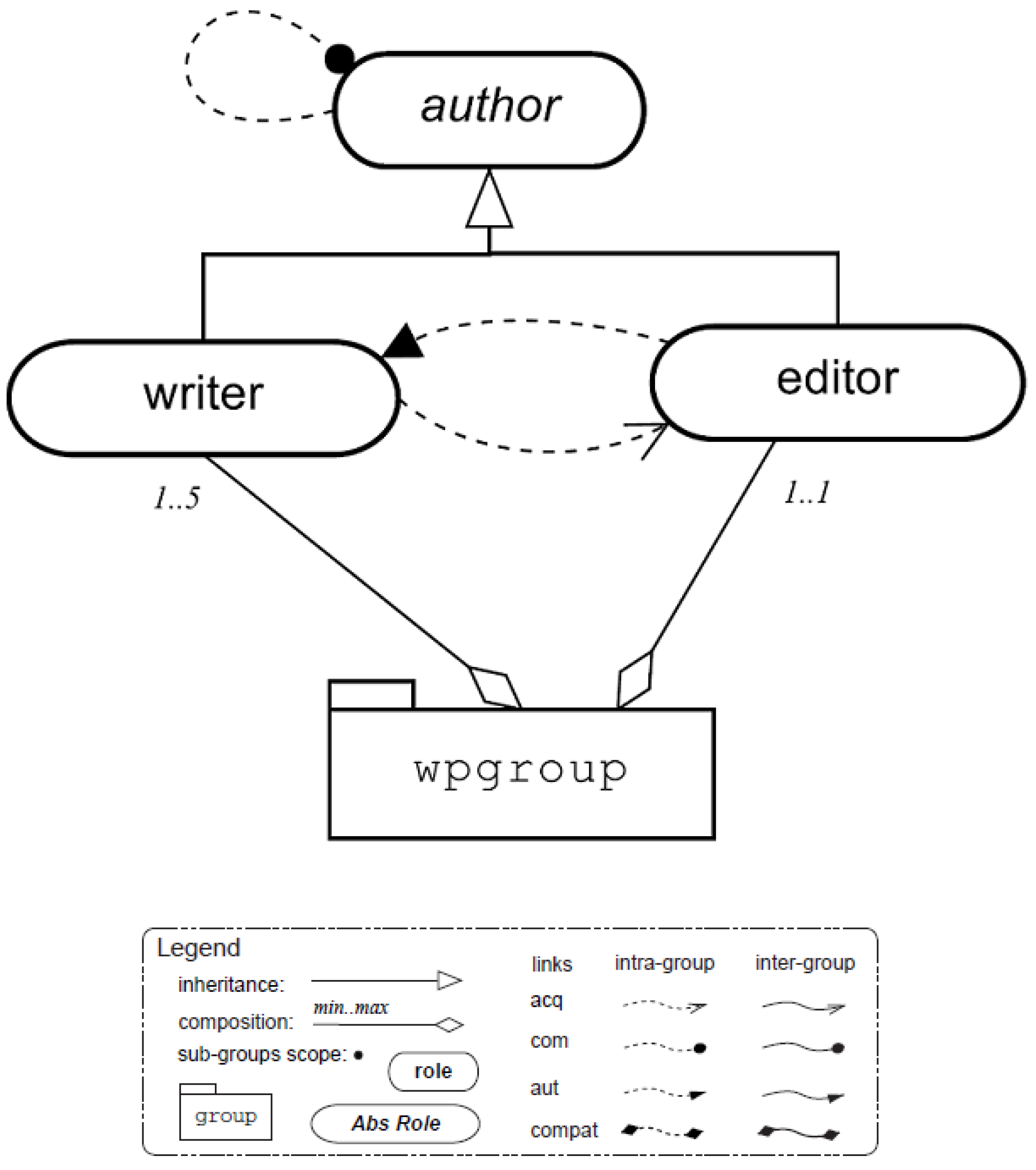
Figure 12 describes the structural specification composed of a
wpgroup group that has two roles:
writer and
editor, and both roles are sub-roles from
author.
The functional specification for this scenario is presented in
Figure 13. According to this scheme, the first part is to conclude a paper draft (
fds). Obeying a sequence, an agent undertakes the
mMan mission and must write a title (
wtitle), an abstract (
wabs), and write the section titles (
wsectitles), ending this first version. In the second branching, named (
sv), the submission version is composed of the goals (
wsec) and writing sections, and to finish the paper, it is necessary to reach two goals in parallel, (
wcon) writing a conclusion and (
wref) writing references.
Table 2 describes the deontic specification defining permissions and obligations for the roles that undertake the missions. The missions are
mMan, project general managing, which is composed of three goals;
mCol collaborating for the writing process; and mission
mBib for the agent which must gather and write the paper references. A description for each goal included in this example can be seen in
Table 3.
In the following subsections, all steps for generating the
, defined in
Section 4.1, will be presented in detail. The goal is to demonstrate how to generate the CPN corresponding to the
oise+ specification under test and generate and recognize the test cases using the proposed approach. In addition, some samples of these test cases are applied in the JaCaMo to verify their correctness.
Section 5.3 demonstrates how to use test cases for identifying errors in a
oise+ specification.
5.2.1. Declarations
According to structural specification, the roles are editor and writer. Hence, the declarations are as follows:
colset R = with editor | writer ;
colset G = with wpgroup ;
colset RG = product R * G ;
var w, e : RG;
var b: BOOL;
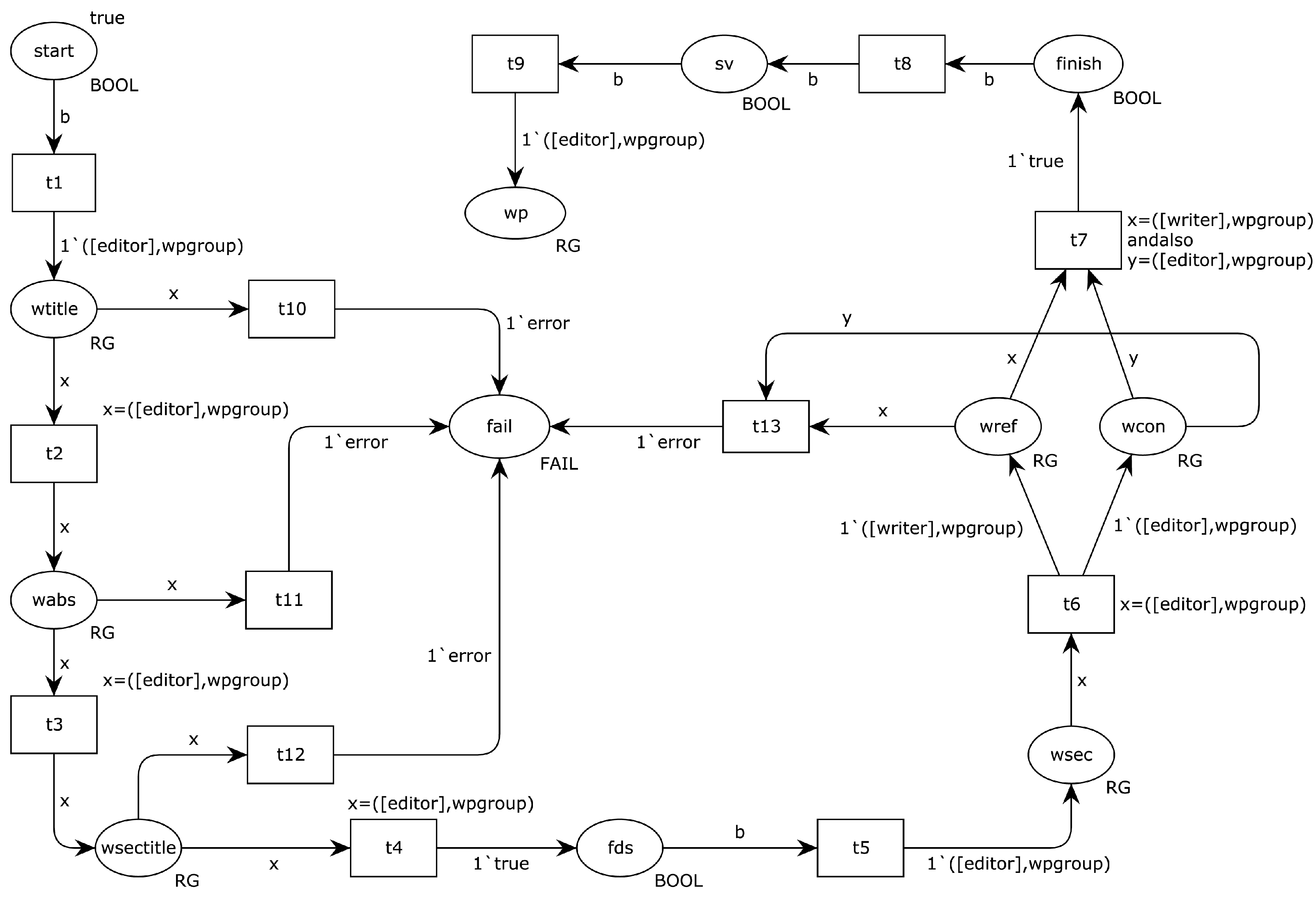
5.2.2. Structure and Inscriptions
In this step, the structure of the
is generated by using the plan operators and the FS goal decomposition tree, and also the inclusion of inscriptions in the network, as shown in
Figure 14. The places represent the goals, and the tokens identify the roles. The inclusion of the inscriptions corresponds to (i) placing the arc expressions to change roles; (ii) arc variables; (iii) identification of places with the name of the goal and the type of color, for example, the goal
with the type
; (iv) and a different identification for each transition. The place called
, the first in the network, does not constitute the specification’s goal. It is just a representation of an initial state where the system is waiting to start execution.
5.2.3. Failures
Figure 15 demonstrates the inclusion of failure paths to all places in the network that are not of the
type, leaving only the goals that have a linked mission and, therefore, a role to carry out actions that satisfy that goal. In these places, a failure path will be created for the same place
, indicating that a failure occurred during the program’s execution. In this example, there are four different failure transitions, named
,
,
, and
. It is already possible to perform simulations on the net from this stage and determine all possible execution paths.
5.2.4. All Paths Criterion
As mentioned above, for counting test cases, two different criteria will be used. First, using the criterion
all paths, where it is necessary to count the net paths directly on
shown in
Figure 15. Here, applying the path counting algorithm directly on the net, we have four different paths representing a failure and one path representing a successful execution, totaling five possible execution paths. Below are the five paths taking into account the places that represent the goals:
.
.
.
.
.
5.2.5. State Transition Path Criterion
The testability of the system must be counted using the state transition path adequacy criterion. Therefore, the first step is the identification of all state nodes that make up the CPN4M state space. The CPNTools has some functions that can facilitate this process, such as , which returns the number of nodes in the state space, where it shows 11 nodes, and , which returns the net marking for a given node n.
There is a description for the state node number 2 of the Writing Paper where the token is in place and all other places on the net are empty. To view all possible states, it is necessary to use the function for all 11 nodes in our example’s state space.
Table 4 shows the markings for each state showing only the places with tokens. Therefore, for example, in the states 9 and 10, two places and two tokens represent the states where the parallelism occurs.
Once the state-space table is generated, a flow control graph is generated that shows the connection between these states using the
of
Figure 15.
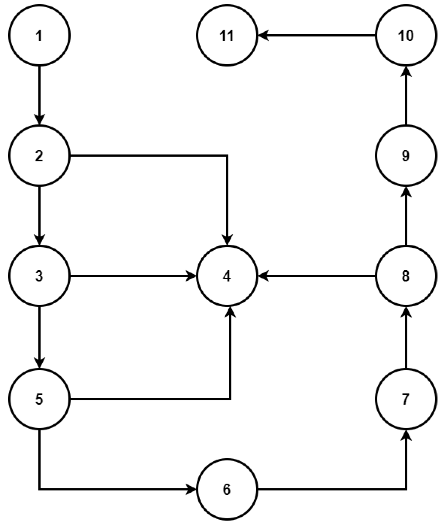
Figure 16 shows the graph with the 11 states and the paths that link them. Applying the path counting algorithm to this graph, we can identify four paths from node 1 to node 4, representing an execution failure. Conversely, one path from node 1 to node 11 represents a successful execution, totaling five different execution paths; they are:
5.2.6. Test Case Generation
With the total number of test paths calculated using a flow control diagram of the state space, it is necessary to generate a description for each of these paths that will be our test cases.
For example, let us take the fifth path, using
Table 4 to identify the place and the token that belong to a given node. It is possible to identify our test case’s goals and roles. In
Table 3, the description of each goal is extracted. Therefore, it is possible to generate
Table 5 with our first test case.
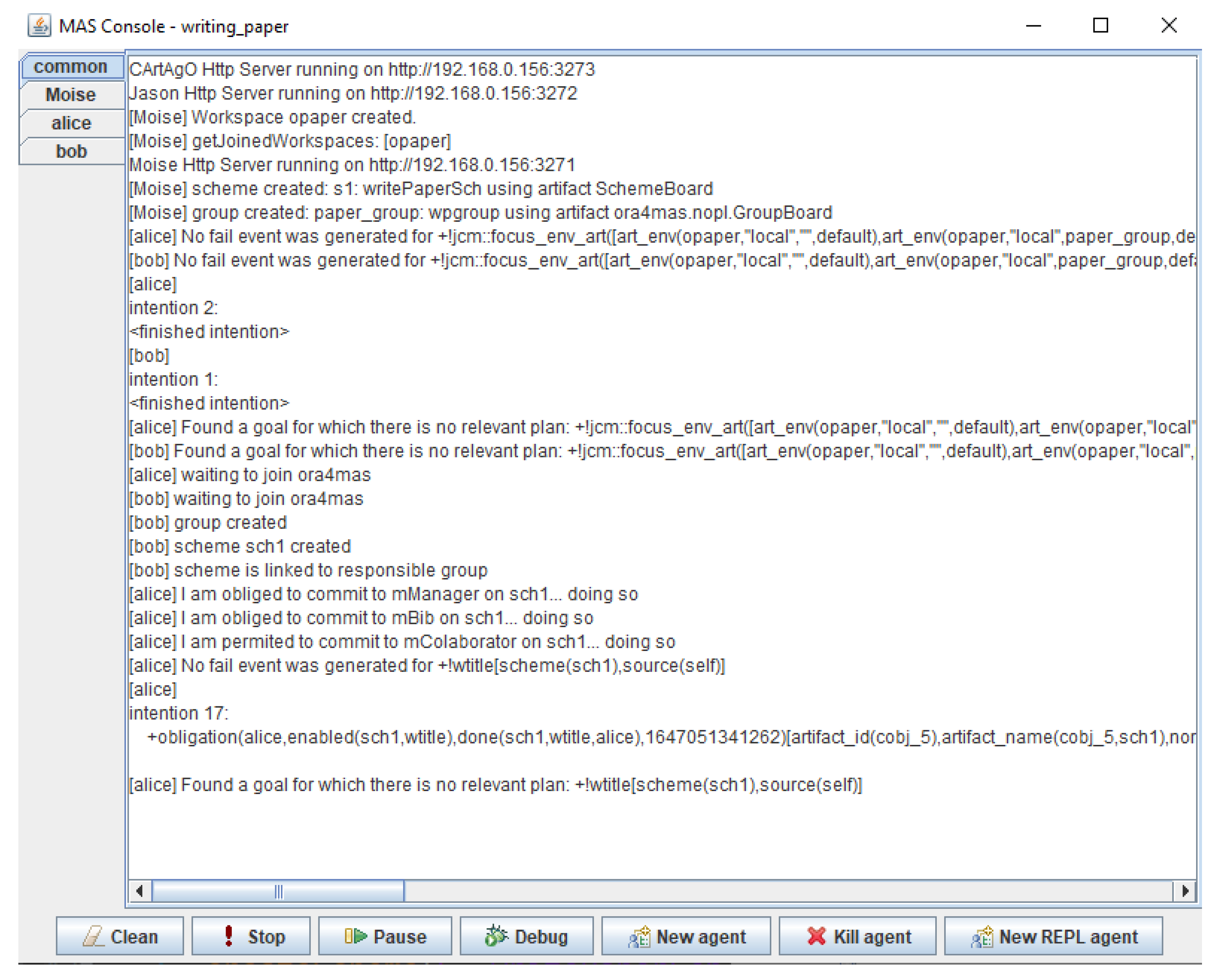
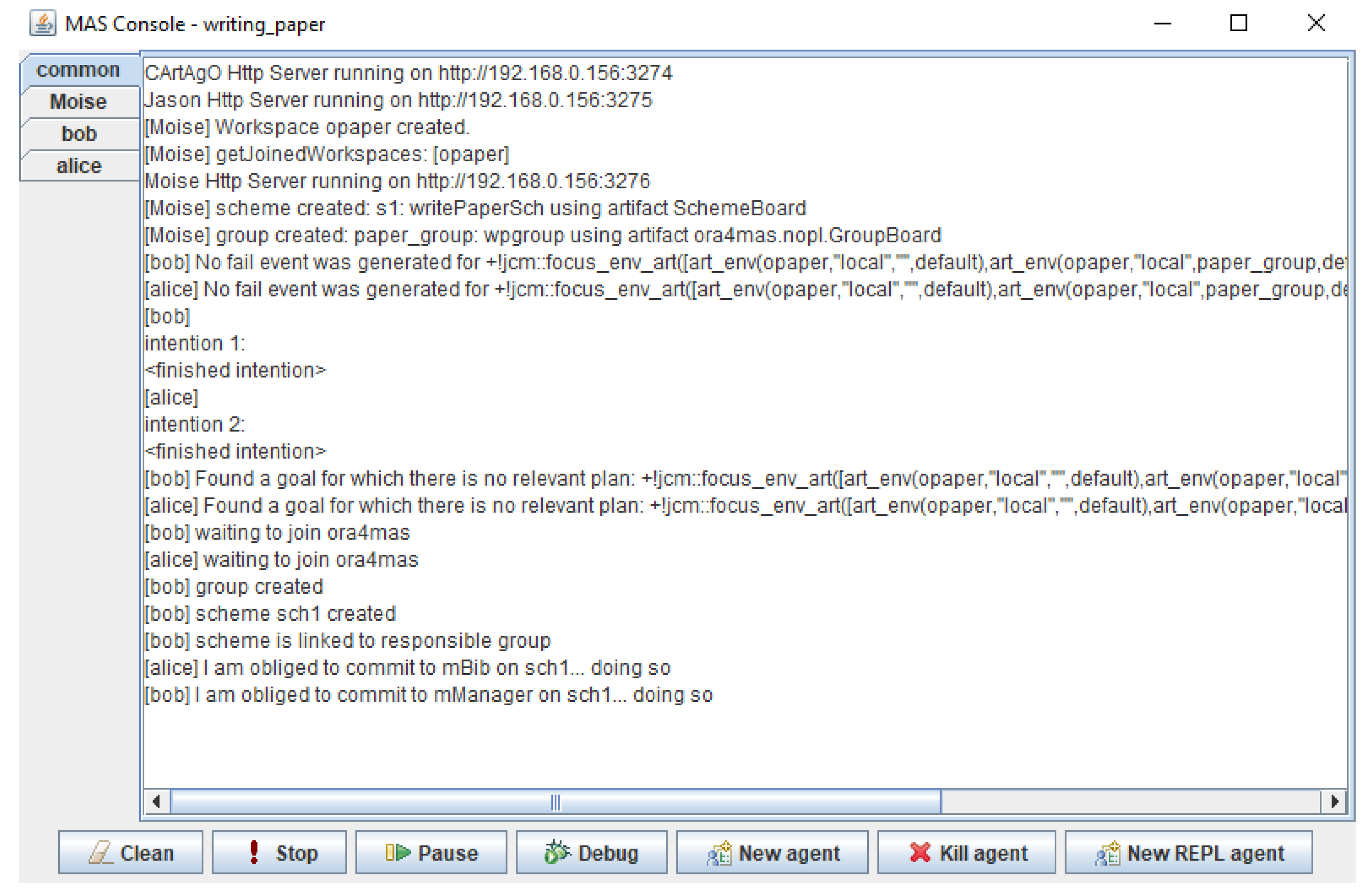
Figure 17 shows an execution of the system for test case number 5. With two agents where Bob represents the
and Alice the
, the program execution was successful, with the agents accomplishing the respective goals correctly. The following subsection will analyze some test cases where failures occur.
5.3. Identifying and Correcting Errors
In this subsection, we exemplify failures identification during a test, inserting errors in the Writing Paper case deontic specification. In the first case, the deontic specification assigns an obligation for a role executing a mission that does not have a plan in the agent’s code to satisfy it. The second case is similar to the first, but the deontic specification now assigns permission to the same role.
The example was tested on the JaCaMo platform using two agents, where the first, called Bob, has the editor role, and the second, called Alice, has the writer role.
5.3.1. Obligation for an Agent Not Eligible for the Plan
Table 6 show a new deontic specification where now a
will have the obligation to performs
mission. Because of this modification, the
had to be reviewed, and the goals
,
,
,
, and
are now associated with the
role, and the new mapping can be seen in
Figure 18.
One of the test cases for this example can be seen in
Table 7, where a fail happens when the
agent tries to fulfill the
goal.
A execution failure can be seen in
Figure 19, where
Bob is an agent with the
role, and
Alice is a
agent who tries to execute the goal
, but due to the fact that this agent does not have a plan to be able to perform this task, it ends up failing.
5.3.2. Permission for an Agent Not Eligible for the Plan
In the second example, an agent with permission for a particular mission does not have the necessary resources to succeed.
Table 8 brings the deontic specification again. However, the second line has been changed where an
(and not a
) has permission for the
mission.
The
also had a modification because now the
performs the
goal (see
Figure 20). The modifications consisted of the output arc expression of the transition
and the guard function of the transition
, replacing
with
. The test case used in the simulation can be seen in
Table 9, where the expected is a successful execution.
The test case used now is described in
Table 9, where a successful execution is predicted. However, in the test execution, the system ends up in an infinite wait.
Figure 21 demonstrates this error in the JaCaMo execution; a
deadlock happens because the
agent
bob does not have any plan that meets the requirements for the
goal, and, due to the deontic relationship permission, he does not commit to the
mission.
5.4. Discussion
The work’s fundamental hypothesis is that an organizational error occurs when an organization is created, depending on the capacity of agents and groups that do not exist or are poorly allocated. In the specific case of oise+, this relationship is materialized in the deontic specification when missions and goals are allocated to groups and their roles.
The colored Petri net, through its structures and colors, is a tool capable of capturing and integrating all the dimensions of an organizational specification. The alternative to this solution would be the reformulation of oise+, including mechanisms and procedures to verify the correctness of integration between the functional, structural, and deontic specifications. However, the Petri net is a consolidated tool for analysis and verification.
It is essential to understand the limits of organizational analysis. When an agent assumes a particular capability but cannot execute it, it is an agent error and not an organizational error. This verification must be performed within the agent specification and coding. The system will fail, but not because of an organization error [
53].
6. Conclusions and Future Works
Multi-agent systems are computing artifacts created to solve problems based on their autonomous agents’ interactions. Similar to distributed systems with emergent behavior, one challenging task in their development is verification. This is especially true for critical systems, such as those employed on manufacturing systems, automation systems, or cyberphysical systems.
Testing and testability are considered parts of a puzzle to seek a high enough true reliability for software [
8]. Nevertheless, it can present a non-deterministic behavior once the same input can generate different outputs.
This paper presented an approach for testing MASs using the CPN for counting and generating test cases. Test simulations were also performed using the generated test cases in JaCaMo. Test results show errors for cases where the agent did not have the necessary resources (plans) to satisfy specific goals. These results were due to a wrong deontic specification and showed the effectiveness of identifying failures at the organizational level.
The tests also showed different results between the agent’s obligation and permission for a mission, where, in the first case, there is an execution failure. On the other hand, the system goes to the on-hold state.
A limitation of the model is the lack of cardinality inclusion, for example, a case where two agents have the obligation for a mission but the maximum allowed by the structural specification is one agent. We can also mention the non-specification of the number of agents assigned to the same role in the test cases.
This work has a significant legacy for future works. This includes another type of test adequacy criterion for flow-oriented testing [
43], where the recording of tokens passing through the arcs is required in a CPN. We believe that this strategy will generate many test cases similar to those of the
state transition path criterion, but with an overlap in the test cases set. Another possibility is the inclusion of cardinality in the
bringing a greater scope to the model. Finally, we will apply this approach in more complex MAS, especially those with a dynamic organization, since they require a complete set of
oise+ structures and their relationships.


 ,
, 


