
Green Hydrogen Storage in an Underground Cavern: A Case Study in Salt Diapir of Spain

 , , and
Abstract
:Featured Application
Abstract
1. Introduction
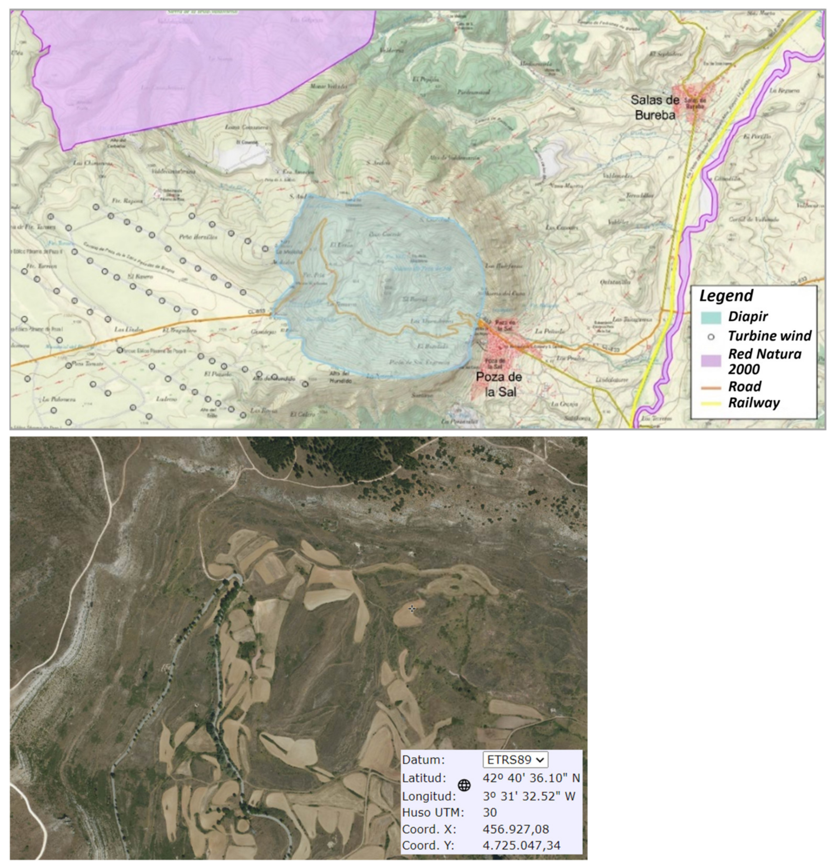
2. Poza de la Sal
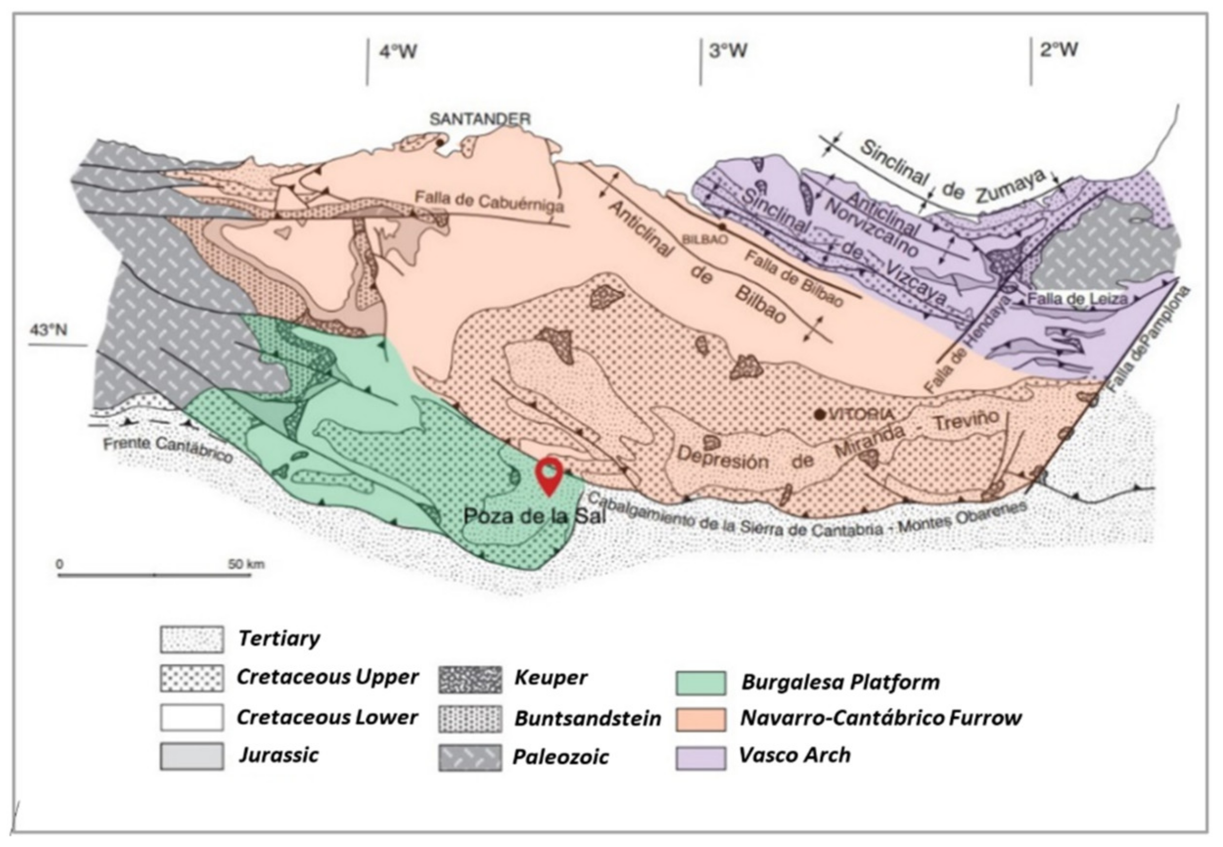
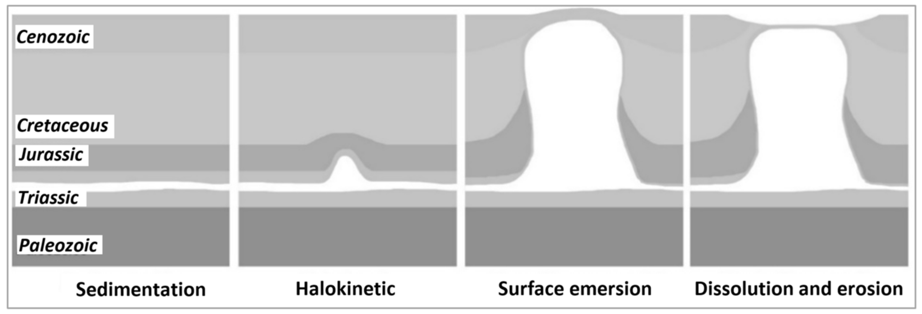
2.1. Regional Geology
2.2. Geological Structure
2.3. Geomorphology
3. Methodology and Results
3.1. Storage Design
3.1.1. Drilling of the Well-Cavern Construction
- The drilling mud must exert a hydrostatic pressure equal to the horizontal stress. Although the earth stress increases with depth, the hydrostatic pressure of the mud will increase accordingly, counteracting the stresses. Water- or oil-based muds are used to pass through salt formations [20]. Since the latter are more expensive and polluting, an aqueous mud saturated in salt will be used in order to avoid dissolution of the borehole walls.
- The casing design must be based on the stresses that the rock will exert, and the chosen material must have sufficient strength to prevent deformation and collapse. Long-term stability must be considered as halite remains relatively stable during drilling but continues to deform over decades of the well’s life [21].
- To isolate the wellbore and prevent the application of non-uniform loads on the casing, the annular spaces between the casings should be filled with cement having high salt concentrations to prevent dissolution of the formation and additives to aid mixing and setting [20].
3.1.2. Cavity Shape
3.1.3. Cavity Size
3.1.4. Leaching Brine Management
3.2. Operational Parameters
3.2.1. Temperature in the Cavern
3.2.2. Lithostatic or Overpressure
3.2.3. Operating Pressure
3.2.4. Density of Hydrogen Storage
3.2.5. Mass of Gas
3.3. Energy Balance
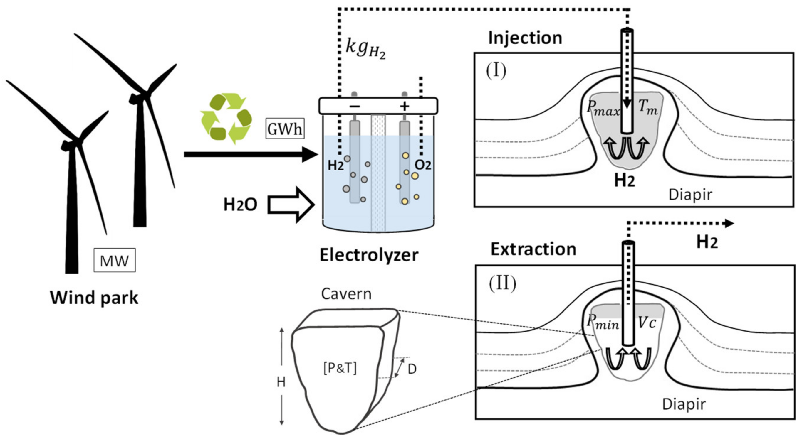
3.4. Operation
Injection and Extraction of Hydrogen
4. Discussion
- −
- Discharge to the sea;
- −
- Geological injection and reuse; and
- −
- Treatment or sale of salt
5. Conclusions
Author Contributions
Funding
Institutional Review Board Statement
Informed Consent Statement
Data Availability Statement
Conflicts of Interest
Abbreviation
| Nomenclature (unit) | |
| C | Working gas energy (kWh) |
| D | Cavern diameter (m) |
| g | Gravity acceleration (m/s2) |
| H | Cavern height (m) |
| M | Molecular mass of hydrogen (kg/mol) |
| mbase | Base gas mass (kg) |
| mwork | Working gas mass (kg) |
| mt | Total gas mass [mbase+mwork] (kg) |
| P | Lithostatic or overload pressure (Pa) |
| Pmin/max | Operating pressure min/max (Pa) |
| R0 | Gas constant (J/K∙mol) |
| R | Cavern Radius (m) |
| Ta | Average cavity temperature (°C) |
| Tsup | Ground surface temperature (°C) |
| V | Cavern volume (m3) |
| z | Cavern base depth (m) |
| Z1/2 | Compressibility factor for Pmax/Pmin |
| Greek symbols (unit) | |
| ∇T | Geothermal gradient (K/m) |
| ρ | Rock salt density (kg/m3) |
| ρmin/max | Gas density min/max (kg/m3) |
| ρH2,min/max | Hydrogen density min/max (kg/m3) |
| Abbreviations (unit) | |
| NC | Normal conditions (1 atm, 0 °C) |
| ECE | Energy consumed in electrolysis (GWh) |
| WES | Wind energy surplus (GWh) |
| LHV | Lower heating value of H2 (kWh/kg) |
| WP | Wind park (MW) |
References
- Kupecki, J.; Skrzypkiewicz, M.; Błesznowski, M. Current advancements in hydrogen technology and pathways to meet decarbonisation. Towards hydrogen societies: Expert group meeting. In Proceedings of the 24th Session of the Conference of the Parties to the United Nations Framework, Convention on Climate Change (UNFCCC)—COP24, Lubelskie, Poland, 12 December 2018. [Google Scholar]
- MITERD. Hoja de Ruta del Hidrógeno: Una Apuesta por el Hidrógeno Renovable; Ministerio para la Transición Ecológica y el Reto Demográfico: Madrid, Spain, 2020.
- Ray, I.; Chakraborty, T.; Roy, D.; Datta, A.; Mandal, B. Production, storage and properties of hydrogen as internal combustion engine fuel: A critical review. Nat. Gas 2013, 240, 48. [Google Scholar]
- Abe, I. Physical and chemical properties of hydrogen. In Energy Carriers and Conversion Systems; EOLSS Publications: Paris, France, 2009; Volume I, Available online: https://www.eolss.net/ebooklib/sc_cart.aspx?File=E3-13-01-01 (accessed on 21 April 2022).
- Heinemann, N.; Alcalde, J.; Miocic, J.M.; Hangx, S.J.T.; Kallmeyer, J.; Ostertag-Henning, C.; Hassanpouryouzband, A.; Thaysen, E.M.; Strobel, G.J.; Schmidt-Hattenberger, C.; et al. Enabling large-scale hydrogen storage in porous media-the scientific challenges. Energy Environ. Sci. 2021, 14, 853–864. [Google Scholar] [CrossRef]
- Las Energías Renovables en el Sistema Eléctrico Español 2020. Red Eléctrica de España. Available online: https://www.ree.es/sites/default/files/publication/2021/06/downloadable/informe_renovables_2020_0.pdf (accessed on 18 April 2022).
- Ozarslan, A. Large-scale hydrogen energy storage in salt caverns. Int. J. Hydrogen Energy 2012, 14265–14277. [Google Scholar] [CrossRef]
- Steven, J.D.; Nathan, S.L.; Matthew, S.; Aggarwal, S.; Arent, D.; Azevedo, I.L.; Benson, S.M.; Bradley, T.; Brouwer, J.; Caldeira, K.; et al. Net-zero emissions energy systems. Science 2018, 360, 114–161. [Google Scholar] [CrossRef] [Green Version]
- Schiebahn, S.; Grube, T.; Robinius, M.; Tietze, V.; Kumar, B.; Stolten, D. Power to gas: Technological overview, systems analysis and economic assessment for a case study in Germany. Int. J. Hydrogen Energy 2015, 40, 4285–4294. [Google Scholar] [CrossRef]
- Bertuccioli, L.; Chan, A.; Hart, D.; Lehner, F.; Madden, B.; Standen, E. Study on Development of Water Electrolysis in the EU. Final Report. July 2014. Available online: https://www.fch.europa.eu/sites/default/files/study%20electrolyser_0.pdf (accessed on 29 April 2022).
- Kruck, O.; Crotogino, F.; Prelicz, R.; Rudolph, T. Overview on All Known Underground Storage Technologies for Hydrogen. HyUnder. Grant Agreement 303417 Deliverable, August 2013; p. 93. Available online: http://hyunder.eu/wp-content/uploads/2016/01/D3.1_Overview-of-all-known-underground-storage-technologies.pdf (accessed on 12 May 2022).
- Caglayan, D.G.; Weber, N.; Heinrichs, H.U.; Linßen, J.; Robinius, M.; Kukla, P.A.; Stolten, D. Technical potential of salt caverns for hydrogen storage in Europe. Int. J. Hydrogen Energy 2020, 45, 6793–6805. [Google Scholar] [CrossRef]
- Schulze, O.; Popp, T.; Kern, H. Development of damage and permeability in deforming rock salt. Eng. Geol. 2001, 61, 163–180. [Google Scholar] [CrossRef]
- Ruiz, C.; Martinez, R.; Recreo, F.; Prado, P.; Campos, R.; Pelayo, M.; Losa, A.D.L.; Hurtado, A.; Lomba, L.; Perez del Villar, L.; et al. Geological Storage of CO2. Site Selection Criteria. Madrid 2006. Ciemat-1085. p. 108. Available online: https://inis.iaea.org/collection/NCLCollectionStore/_Public/38/030/38030356.pdf?r=1 (accessed on 19 April 2022).
- Robles, S.; Aranburu, A.; Apraiz, A. La Cuenca Vasco-Cantábrica: Génesis y evolución tectonosedimentaria. Enseñ. Cienc. Tierra 2014, 22, 99–114. [Google Scholar]
- Pedreira, D. Estructura de la Zona de Transición de los Pirineos y la Cordillera Cantábrica. Ph.D. Thesis, Universidad de Oviedo, Oviedo, Spain, 2004; pp. 1–343. [Google Scholar]
- Khaledi, K.; Mahmoudi, E.; Datcheva, M.; Tom Schanz, T. Stability and serviceability of underground energy storage caverns in rock salt subjected to mechanical cyclic loading. Int. J. Rock. Mech. Min. 2016, 86, 115–131. [Google Scholar] [CrossRef]
- Howard, B.J.S.; Veldhuis, I.; Neil Richardson, R. Underground hydrogen storage in the UK. Geol. Soc. Lond. Spec. Publ. 2009, 313, 217–226. [Google Scholar] [CrossRef] [Green Version]
- Korzeniowski, W.; Poborska-Młynarska, K.; Skrzypkowski, K.; Zagórski, K.; Chromik, M. Cutting Niches in Rock Salt by Means of a High-Pressure Water Jet in Order to Accelerate the Leaching of Storage Caverns for Hydrogen or Hydrocarbons. Energies 2020, 13, 1911. [Google Scholar] [CrossRef] [Green Version]
- Barker, J.W.; Feland, K.W.; Tsao, Y.-H. Drilling Long Salt Sections Along the U.S. Gulf Coast. SPE Drill. Completion 1994, 9, 185–188. [Google Scholar] [CrossRef]
- Wang, H.; Samuel, R. Geomechanical Modeling of Wellbore Stability in Salt Formations. Soc. Pet. Eng. 2014, 31, 261–272. [Google Scholar] [CrossRef]
- Cyran, K.; Kowalski, M. Shape Modelling and Volumen Optimisation of Salt Caverns for Energy Storage. Appl. Sci. 2021, 11, 423. [Google Scholar] [CrossRef]
- Papadias, D.D.; Ahluwalia, R.K. Bulk storage of hydrogen. Int. J. Hydrogen Energy 2021, 46, 34527–34541. [Google Scholar] [CrossRef]
- Barron, T.F. Regulatory, technical pressures prompt more US salt-cavern gas storage. Oil Gas J. 1994, 92, 55–67. [Google Scholar] [CrossRef]
- Portarapillo, M.; Di Benedetto, A. Risk Assessment of the Large-Scale Hydrogen Storage in Salt Caverns. Energies 2021, 14, 2856. [Google Scholar] [CrossRef]
- Albrecht, U.; Bünger, U.; Michalski, J.; Raksha, T.; Wurster, R.; Zerhusen, J. International Hydrogen Strategies. A Study Commissioned by and in Cooperation with the World Energy Council Germany 2020. Final Report. Available online: https://www.researchgate.net/publication/345163207 (accessed on 12 April 2022).
- Bell, I.H.; Wronski, J.; Quoilin, S.; Lemort, V. Pure and pseudo-pure fluid thermophysical property evaluation and the open-source thermophysical property library coolprop. Ind. Eng. Chem. Res. 2014, 53, 2498–2508. [Google Scholar] [CrossRef] [Green Version]
- Londe, L. Hydrogen Caverns Are a Proven, Inexpensive and Reliable Technology. 2018. Available online: https://medium.com/@ch2ange (accessed on 9 May 2022).
- Sainz-Garcia, A.; Abarca, E.; Rubi, V.; Grandia, F. Assessment of feasible strategies for seasonal underground hydrogen storage in a saline aquifer. Int. J. Hydrogen Energy 2017, 42, 16657–16666. [Google Scholar] [CrossRef]
- Cihlar, J.; Mavins, D.; Van der Leun, K. Picturing the Value of Underground Gas Storage to the European Hydrogen System; Guidehouse: Chicago, IL, USA, 2021; p. 52. [Google Scholar]
- Panfilov, M. Underground and pipeline hydrogen storage. In Compendium of Hydrogen; Gupta, R.B., Ed.; Elsevier: Amsterdam, The Netherlands, 2016; p. 92. [Google Scholar]
- He, T.; Rong, Z.; Zheng, J.; Ju, Y.; Linga, P. LNG cold energy utilization: Prospects and challenges. Energy 2019, 170, 557–568. [Google Scholar] [CrossRef]
- Bai, M.; Song, K.; Sun, Y.; He, M.; Li, Y.; Sun, J. An overview of hydrogen underground storage technology and prospects in China. J. Pet. Sci. Eng. 2014, 124, 132–136. [Google Scholar] [CrossRef]
- Lord, A.S.; Kobos, P.H.; Borns, D.J. Geologic storage of hydrogen: Scaling up to meet city transportation demands. Int. J. Hydrogen Energy 2014, 39, 15570–15582. [Google Scholar] [CrossRef] [Green Version]
- Wallace, R.L.; Cai, Z.; Zhang, H.; Zhang, K.; Guo, C. Utility-scale subsurface hydrogen storage: UK perspectives and technology. Int. J. Hydrogen Energy 2021, 46, 25137–25159. [Google Scholar] [CrossRef]
- Heinemann, N.; Scafidi, J.; Pickup, G.; Thaysen, E.M.; Hassanpouryouzb, A.; Wilkinson, M.; Satterley, A.K.; Booth, M.G.; Edlmann, K.; Haszeldine, R.S. Hydrogen storage in saline aquifers: The role of cushion gas for injection and production. Int. J. Hydrogen Energy 2021, 46, 39284–39296. [Google Scholar] [CrossRef]
- Hemme, C.; Van Berk, W. Hydrogeochemical Modeling to Identify Potential Risks of Underground Hydrogen Storage in Depleted Gas Fields. Appl. Sci. 2018, 8, 2282. [Google Scholar] [CrossRef] [Green Version]
- Crotogino, F.; Donadei, S.; Bünger, U.; Landinger, H. Large-scale hydrogen underground storage for securing future energy supplies. In Proceedings of the 18th World Hydrogen Energy Conference 2010—WHEC 2010, Zürich, Switzerland, 16–21 May 2010; pp. 37–45. [Google Scholar]


| Temperature (K) | ||||||||
|---|---|---|---|---|---|---|---|---|
| 250 | 273.15 | 298.15 | 350 | 400 | 450 | 500 | ||
| Pressure (bar) | 1 | 1.00070 | 1.00004 | 1.0006 | 1.00055 | 1.00047 | 1.00041 | 1.00041 |
| 5 | 1.00337 | 1.00319 | 1.00304 | 1.00270 | 1.00241 | 1.00219 | 1.00196 | |
| 10 | 1.00672 | 1.00643 | 1.00605 | 1.00540 | 1.00484 | 1.00435 | 1.00395 | |
| 50 | 1.03387 | 1.03235 | 1.03037 | 1.02701 | 1.02411 | 1.02159 | 1.01957 | |
| 100 | 1.06879 | 1.06520 | 1.06127 | 1.05369 | 1.04807 | 1.04314 | 1.03921 | |
| 150 | 1.10404 | 1.09795 | 1.09189 | 1.08070 | 1.07200 | 1.06523 | 1.05936 | |
| 200 | 1.14056 | 1.13177 | 1.12320 | 1.10814 | 1.09631 | 1.08625 | 1.07849 | |
| 250 | 1.17789 | 1.16617 | 1.15499 | 1.13543 | 1.12034 | 1.10793 | 1.08764 | |
| 300 | 1.21592 | 1.20101 | 1.18716 | 1.16300 | 1.14456 | 1.12957 | 1.11699 | |
| 350 | 1.25461 | 1.23652 | 1.21936 | 1.19051 | 1.16877 | 1.15112 | 1.13648 | |
| 400 | 1.29379 | 1.27220 | 1.25205 | 1.21842 | 1.19317 | 1.17267 | 1.15588 | |
| 450 | 1.33332 | 1.30820 | 1.28487 | 1.24634 | 1.21739 | 1.19439 | 1.17533 | |
| 500 | 1.37284 | 1.34392 | 1.31784 | 1.27398 | 1.24173 | 1.21583 | 1.19463 | |
| 600 | 1.45188 | 1.41618 | 1.38797 | 1.33010 | 1.29040 | 1.2592 | 1.23373 | |
| 700 | 1.53161 | 1.48880 | 1.44991 | 1.38593 | 1.33914 | 1.30236 | 1.27226 | |
Publisher’s Note: MDPI stays neutral with regard to jurisdictional claims in published maps and institutional affiliations. |
© 2022 by the authors. Licensee MDPI, Basel, Switzerland. This article is an open access article distributed under the terms and conditions of the Creative Commons Attribution (CC BY) license (https://creativecommons.org/licenses/by/4.0/).
Share and Cite
Valle-Falcones, L.M.; Grima-Olmedo, C.; Mazadiego-Martínez, L.F.; Hurtado-Bezos, A.; Eguilior-Díaz, S.; Rodríguez-Pons, R. Green Hydrogen Storage in an Underground Cavern: A Case Study in Salt Diapir of Spain. Appl. Sci. 2022, 12, 6081. https://0-doi-org.brum.beds.ac.uk/10.3390/app12126081
Valle-Falcones LM, Grima-Olmedo C, Mazadiego-Martínez LF, Hurtado-Bezos A, Eguilior-Díaz S, Rodríguez-Pons R. Green Hydrogen Storage in an Underground Cavern: A Case Study in Salt Diapir of Spain. Applied Sciences. 2022; 12(12):6081. https://0-doi-org.brum.beds.ac.uk/10.3390/app12126081
Chicago/Turabian StyleValle-Falcones, Laura M., Carlos Grima-Olmedo, Luis F. Mazadiego-Martínez, Antonio Hurtado-Bezos, Sonsoles Eguilior-Díaz, and Ramón Rodríguez-Pons. 2022. "Green Hydrogen Storage in an Underground Cavern: A Case Study in Salt Diapir of Spain" Applied Sciences 12, no. 12: 6081. https://0-doi-org.brum.beds.ac.uk/10.3390/app12126081