
Case Study on the Deformation Coupling Effect of a Deep Foundation Pit Group in a Coastal Soft Soil Area


1
Department of Geotechnical Engineering, Tongji University, Shanghai 200092, China
2
Department of Civil Engineering, University of Shanghai for Science and Technology, Shanghai 200093, China
*
Author to whom correspondence should be addressed.
Appl. Sci. 2022, 12(12), 6205; https://0-doi-org.brum.beds.ac.uk/10.3390/app12126205
Submission received: 12 May 2022
/
Revised: 14 June 2022
/
Accepted: 15 June 2022
/
Published: 18 June 2022
(This article belongs to the Special Issue Recent Progress on Advanced Foundation Engineering)
Abstract
:Simultaneous construction of adjacent projects may lead to emergencies in a foundation pit group, which significantly affects the deformation and safety of foundation pits. In this study, the deformation characteristics of a deep foundation pit group and the mutual interactions among the adjacent foundation pits were observed by a monitoring system during excavation. Field data of the foundation pit group, including the lateral deflections of the enclosure pile, the ground subsidence, as well as the vertical column movements, were analyzed and compared with individual excavations in Shanghai. The field data showed that the excavation of the adjacent foundation pit reduced the lateral deformation of the enclosure structure, caused by the reduction of active earth pressure acting on the retaining pile. Furthermore, the foundation pit excavated later caused upward movements of the soil between them. However, the foundation pit excavated earlier had a negligible influence on the vertical column movements of the foundation pit excavated later. Due to the optimized excavation sequence of the deep foundation pit group, the deformation of this special excavation was well controlled.
1. Introduction
With the accelerated development of urbanization in China, the concentration of population in cities has brought many challenges to the construction of infrastructure. Not only is the space above ground utilized for new facilities, but also sufficient attention has been paid to the development of urban underground space. Therefore, numerous underground constructions, such as subway stations and underground shopping malls, emerge during the expansion of urban areas. Meanwhile, the volume of single buildings continues to increase, and the structures become more complex; thus, the construction of large-scale and multiple-blocked foundation pits are more common [1,2,3,4,5,6]. The design and construction of an excavation group is becoming increasingly common in engineering practices. Compared with the excavation of a single foundation pit, a foundation pit group would experience larger earth pressure unloading, larger superposition of earth pressure and deformation, and a longer construction period. In addition, more significant temporal and spatial effects on a foundation pit group would give rise to excessive deformation and greater construction risks. Therefore, extensive studies and research have been performed to provide insight into the deformation of foundation pits and the surrounding facilities by many scholars [7,8,9,10,11,12,13,14]. Liu et al. [15] observed the deformation characteristics of an 18.4 m deep triangular foundation pit in Shanghai soft clays using a monitoring system. Dan and Sahu [16] proposed a new theoretical approach to evaluating ground deformation and wall deflection at any section within the influence zone of a braced excavation. Based on the finite element method, Lim and Ou [17] analyzed the stress state of soils in the process of deep excavation. Li [18] studied the active earth pressure and lateral wall deflections in a deep excavation group via theoretical and numerical analyses. The effect of soil width on the transition of lateral earth pressure was investigated. Zhang [19] proposed the superposition mechanism of the environmental impact of a single excavation and investigated the environmental deformation, such as the lateral deformation of the retaining structure, the ground settlement, and the deformation of nearby buildings and pipes, induced by the excavation group. Chen et al. [20] proposed the divided alternate excavation method (DAEM) to mitigate the influence of a newly excavated underground construction on existing tunnels and the feasibility and advantages of DAEM in limiting the deformation of tunnels were well demonstrated by field measurements. Wang et al. [21] introduced the concept of a deep excavation group and systematically studied its characteristics through several project examples, which gave insight into key scientific problems regarding deep excavation groups. Dai et al. [22] investigated synchronous excavations in Shanghai soft soils and analyzed the effect of the buffer width of synchronous excavations by numerical simulation based on a practical project.
An excavation group composed of four foundation pits in Shanghai was investigated in this paper to analyze the interaction between adjacent pits and the complex deformation mechanism. The whole excavation project covered an area of 38,744 m2 and was excavated to 10.6 m below the ground surface. To ensure the safety of the foundation pit group, the overall construction principle of the project was that the main structure can be constructed at the same time, but the foundation pit should not be excavated until the underground structure of the adjacent foundation pit is finished. Thus, the space–time effect of the foundation pit group was obvious due to the large total area, the large excavation depth, the long construction period, the multiple unloading, and the superimposed influences of the foundation pits. The influence of the relative position and construction sequence of each foundation pit on the deformation of the retaining structure and stratum was monitored and discussed to reveal the superposition mechanism of deformation for the foundation pit group. The general trends in the lateral deformation of the enclosure pile, ground settlement, and vertical column movement are expounded upon, with the aim of proposing a conceptual design method and deformation control measures for the design and construction of the foundation pit group.
2. Project Description
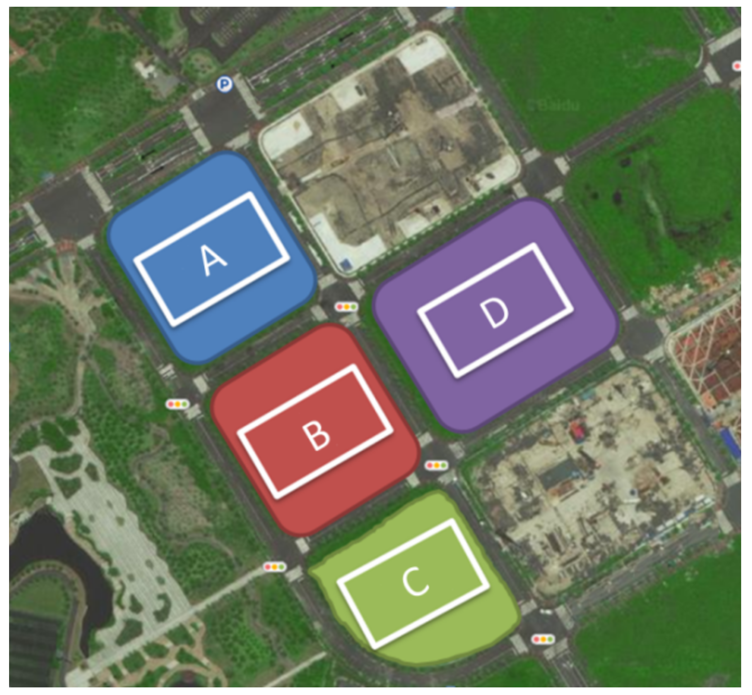
The project reported in this paper was located at the western part of Qiantan International Business District, Pudong New District in Shanghai. The project consists of nine foundation pits and four of them are investigated in this paper. For a better illustration, the four foundation pits are referred to as pit A, pit B, pit C, and pit D in Figure 1. The four foundation pits were separated from each other by approximately 16 m, and foundation pit B was enclosed by the other three pits. In addition, the built wall around each plot was close to the edge of the four pits, resulting in the limited construction space for foundation pit B. According to the site survey, the four foundation pits concerned in this paper were surrounded by built roads and municipal pipelines buried underground on both sides of the roads. The main structures inside pit A, pit B, and pit C consisted of shear walls and frame structures, and frame structures were only used for pit D. The four buildings were all supported by piled-raft foundations, and bored cast-in-place piles with a diameter of 600 mm were employed for the piled-raft foundations. The effective length of the bored cast-in-place pile was 26 or 35 m. The details of the area, the perimeter, the depth, and the main structures of the four foundation pits are shown in Table 1. Both the safety grade and the environmental protection grade of the four foundation pits were of grade II according to the Chinese technical specification for retaining and protection of building foundation excavations (JGJ120-2012).
3. Site Description
A geological survey report was formed via conducting a series of laboratory and field tests before designing the foundation pits. The geological survey report showed that the landform of the site is a coastal plain, which refers to an area of flat, low-lying land next to the ocean. According to the field investigation, the soil strata encountered within 65 m below the ground surface could be divided into five layers: silty clay, muddy silty clay, muddy clay, sandy clay, and silty clay. The physical and mechanical parameters of the soil layers given in Table 2 were determined by direct shear tests, oedometer tests, vane shear strength tests, standard penetration tests (SPTs), and cone penetration tests (CPTs). The data in Table 2 were from the geological survey report. It should be noted that similar to the soil parameters in the same area [1,2,23], the friction angles of silty clay and muddy clay were smaller than 20° and, thus, were correct. The dynamic change in the groundwater level was mainly affected by rainfall, surface evaporation, and surface water. Confined groundwater in the soil layer ➄2-1 had a great influence on the deformation of the foundation pits. This was because excavation of the foundation pit reduced the total weight of the overlying soil, and then the head pressure of the confined water could crack or destroy the bottom plate of the foundation pit, resulting in hydraulic heave.
4. Retaining Structure and Instrumentation
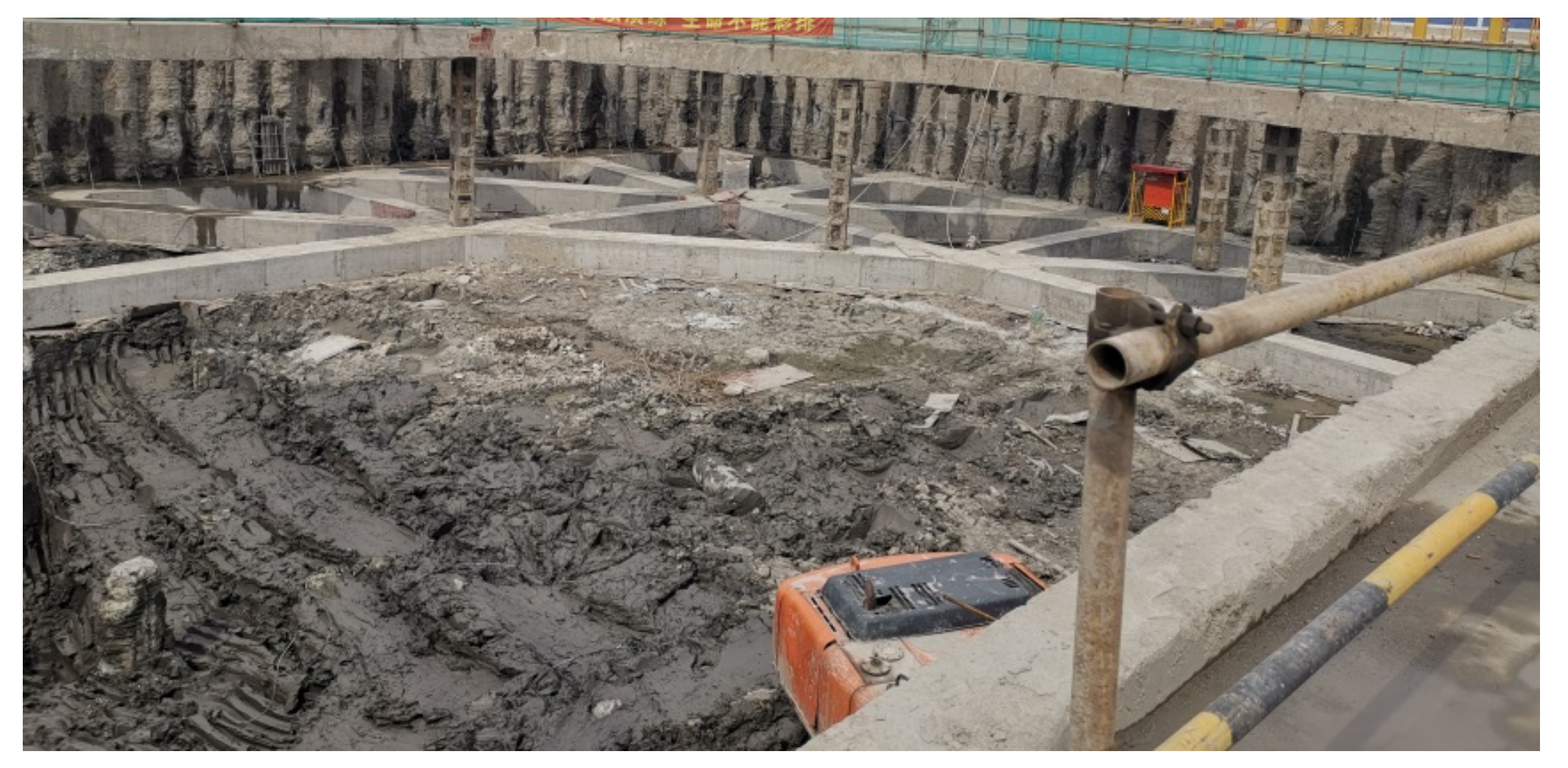
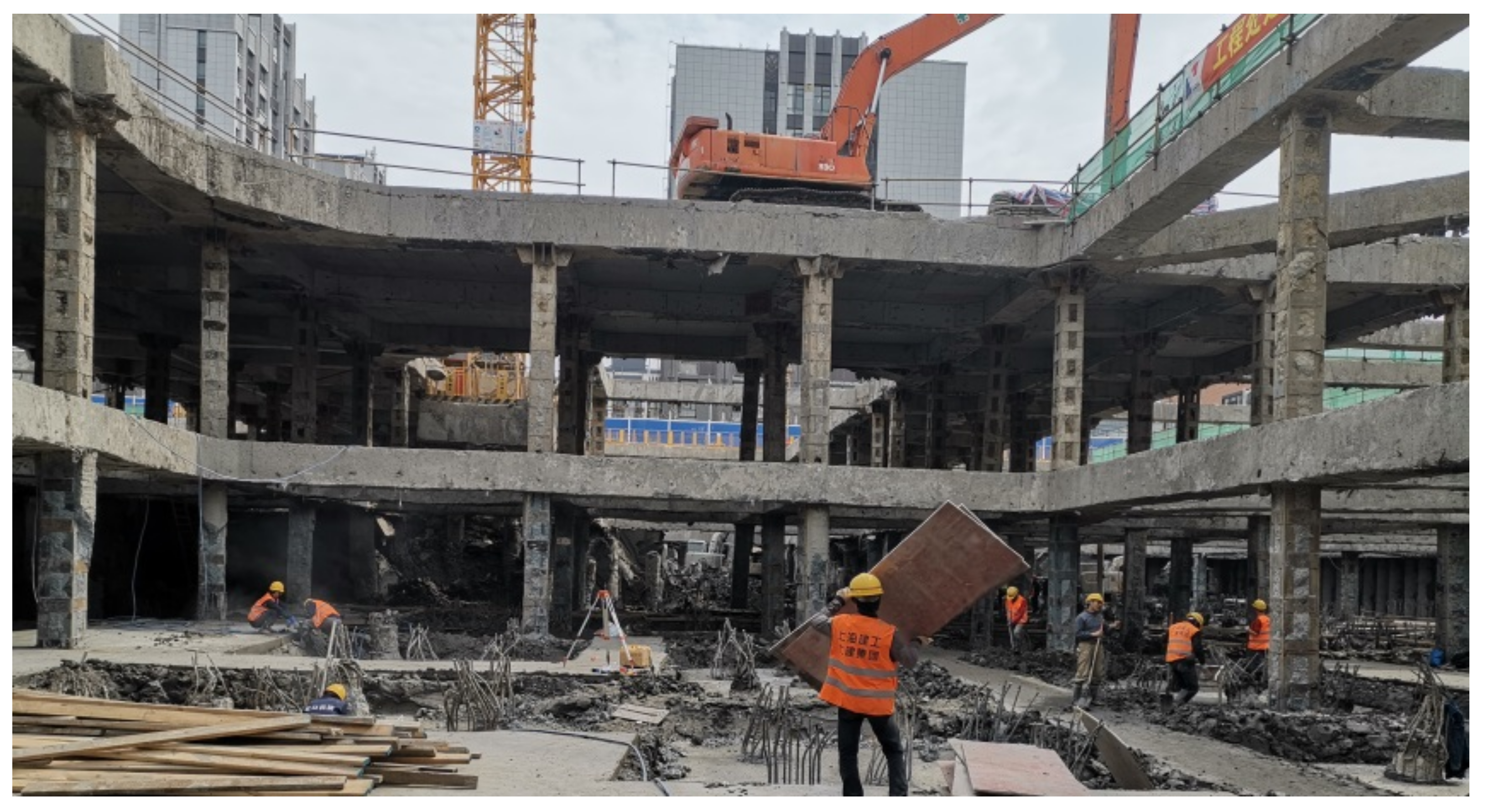
Figure 2, Figure 3, Figure 4 and Figure 5 show the plane views of the enclosure structure of foundation pits A~D, respectively. Sheet pile-braced cuts with two internal support beams were selected as the retaining structure. The diameter of the bored cast-in-place pile was 800 mm, and the clear spacing was 200 mm. The length of the bored cast-in-place pile varied for different foundation pits, ranging from 19 to 22 m. Triaxial mixing piles were used as the waterproof curtain. To reduce the mutual influence during foundation pit construction, the construction sequence of the four foundation pits was optimized. The principle of the construction sequence was that adjacent foundation pits should not be excavated at the same time. In general, the construction sequence was to construct foundation pits A, C, and D on the outside first and then foundation pit B in the middle. The zoned excavation technique was adopted for the excavation of the second and third layers of the foundation pits. The zoned excavation technique refers to dividing a foundation pit into different areas for excavation to ensure the safety of the foundation pit itself and the surrounding environment. After the excavation of each layer of the foundation pits, the strut (i.e., lateral support inside the foundation pit) or the base slab should be cast in time. A detailed construction schedule is presented in Table 3. The excavation processes is shown in Figure 6 and Figure 7.
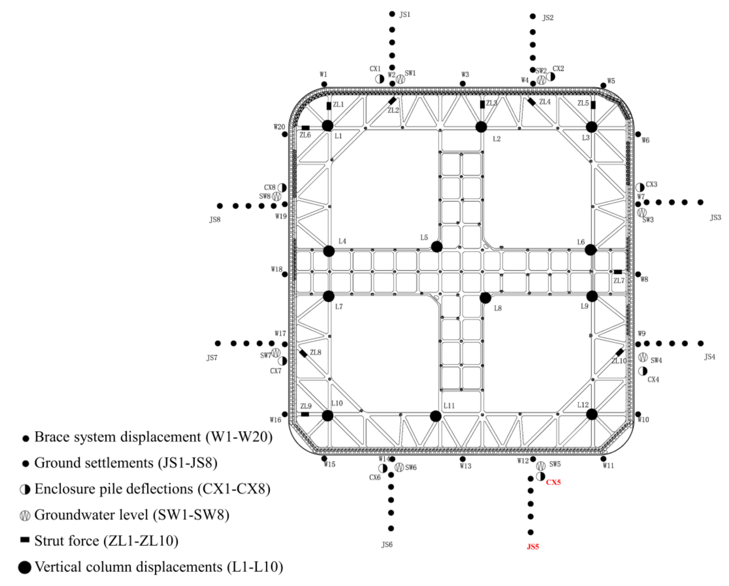
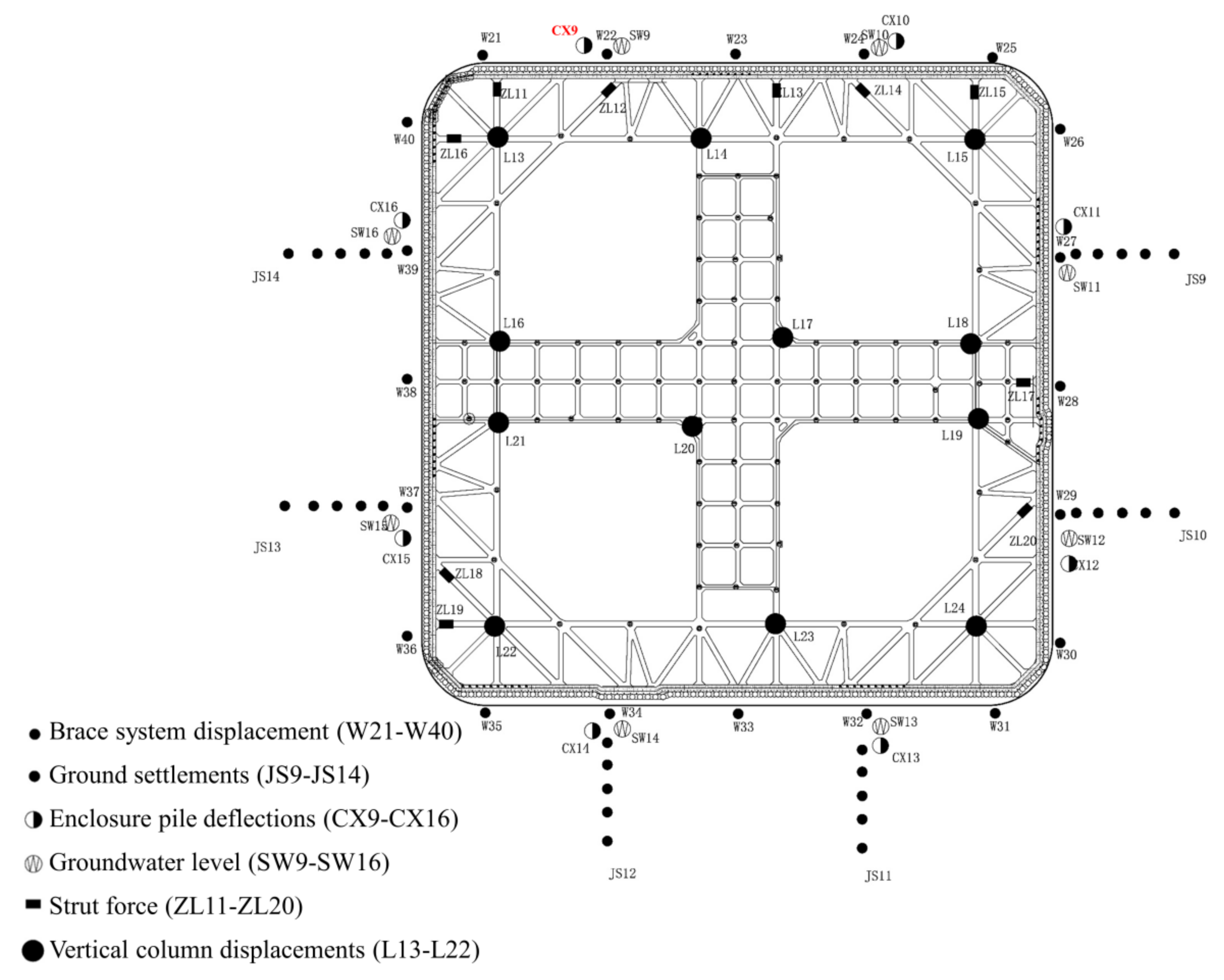
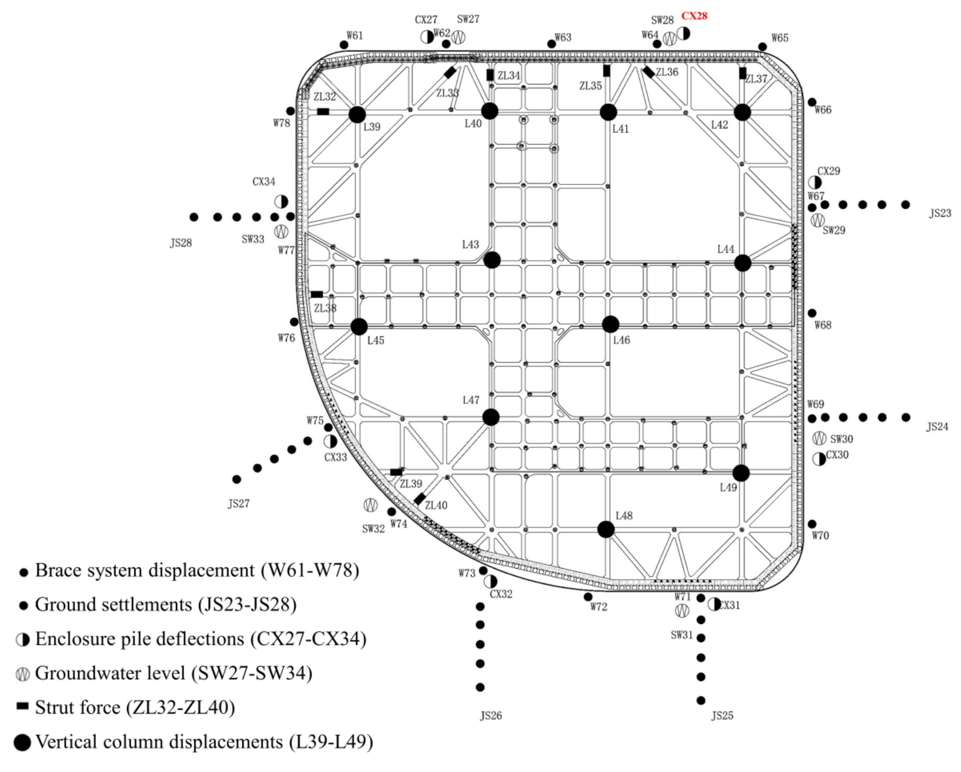
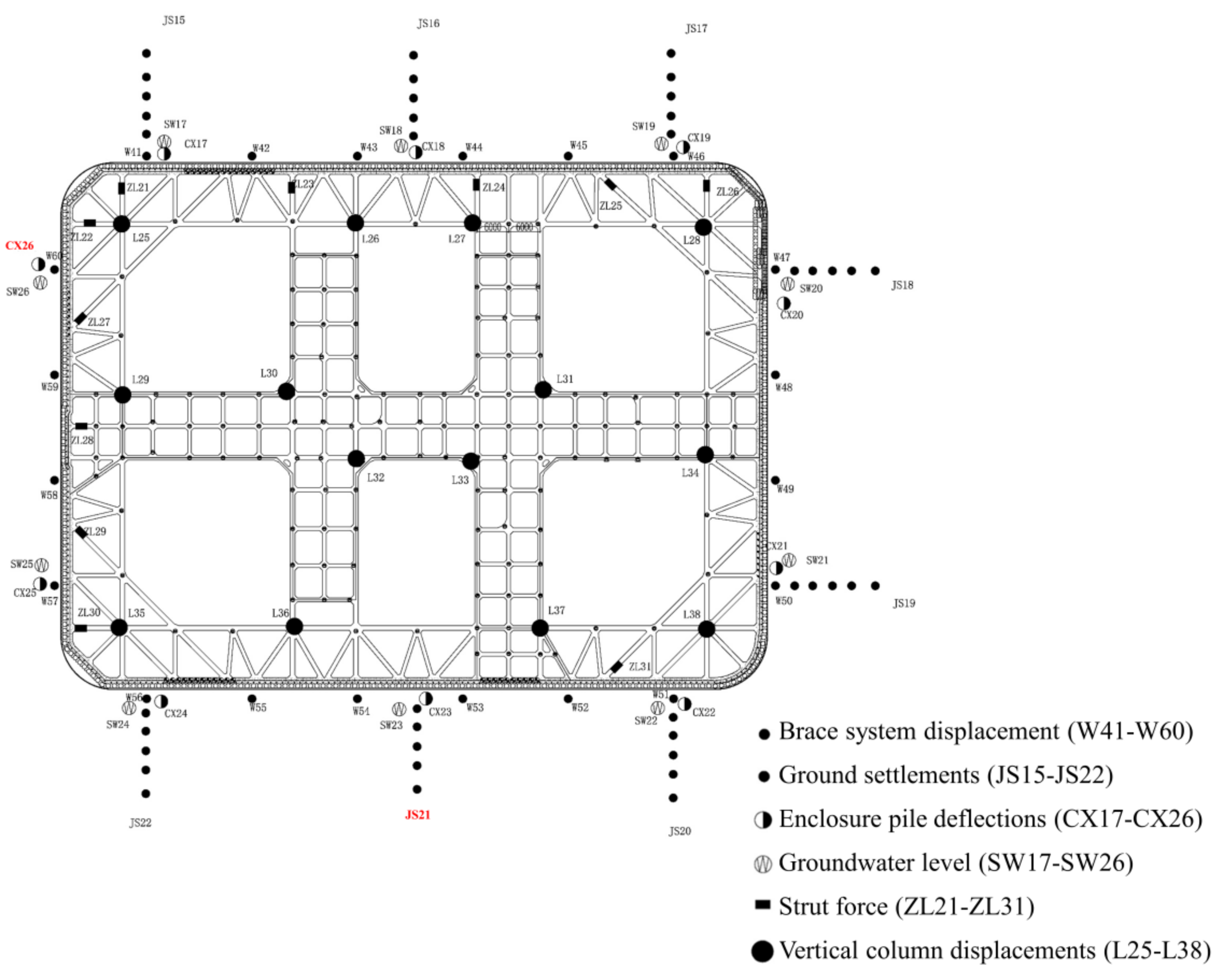
Monitoring the deformation of the retaining system and surrounding strata during excavation is of great significance to ensure the safety of the foundation pit. The monitoring scheme was formulated according to the Specification for engineering measurement (GB50026-2007), Specification for the first and second order leveling (GB12897-2006), Building foundation pit monitoring technical specifications (GB50497-2009) and Monitoring rules for construction of foundation pit engineering in Shanghai (DG/TJ08-2001-2006). The main instruments of this project included two parts. One was the surrounding environmental monitoring: the settlement behind the enclosure piles surveyed by a level instrument (designated as JS1.1–JS1.5 to JS28.1–JS28.5). The other one was the enclosure structure monitoring: lateral deflections of the enclosure pile surveyed by inclinometer casings (designated as CX1–CX34) and vertical column movements surveyed by a level instrument (designated as L1–L49). The layout of the instruments is shown in Figure 2, Figure 3, Figure 4 and Figure 5.
5. Analysis of the Monitored Results
5.1. Lateral Deflections of the Enclosure Pile
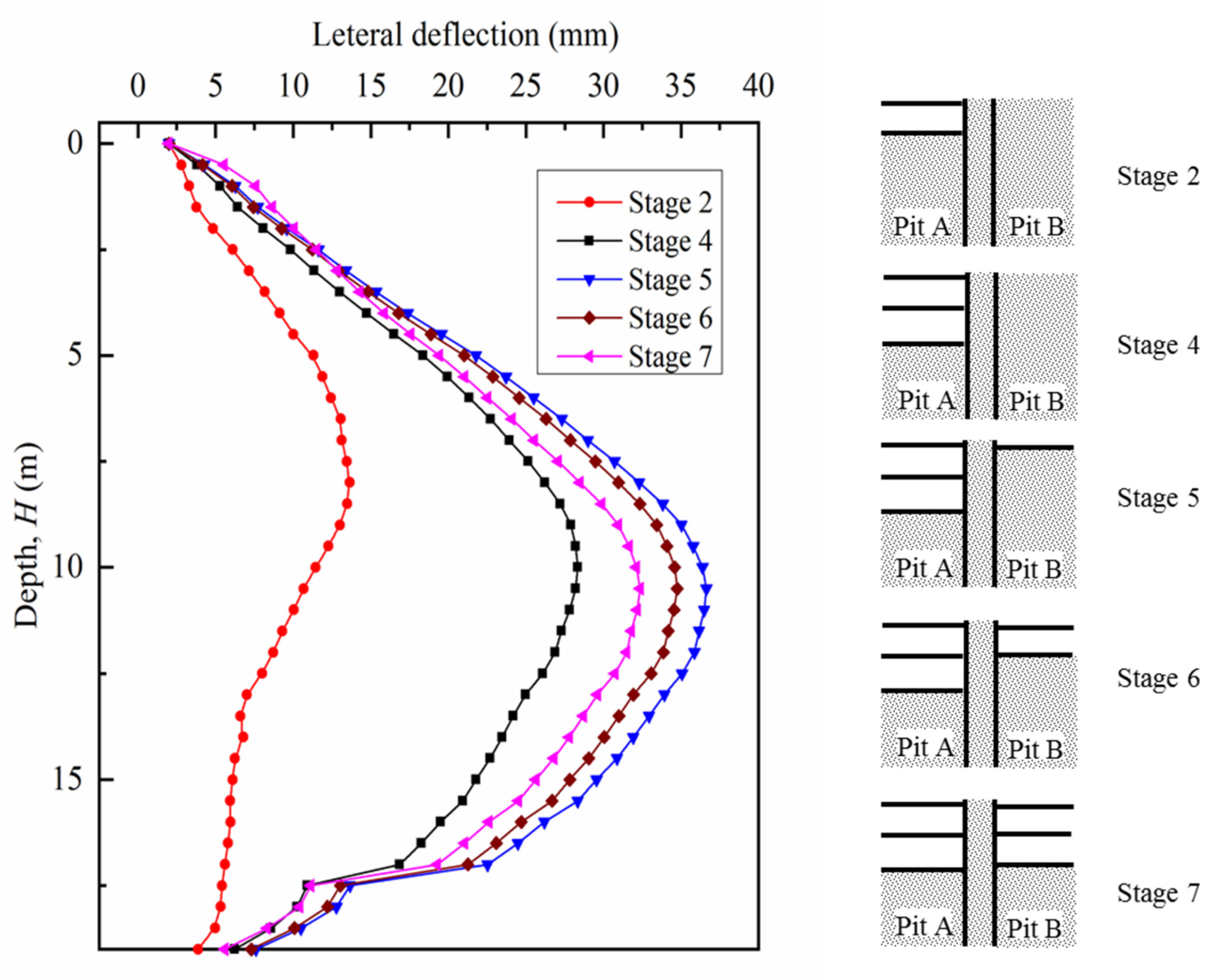
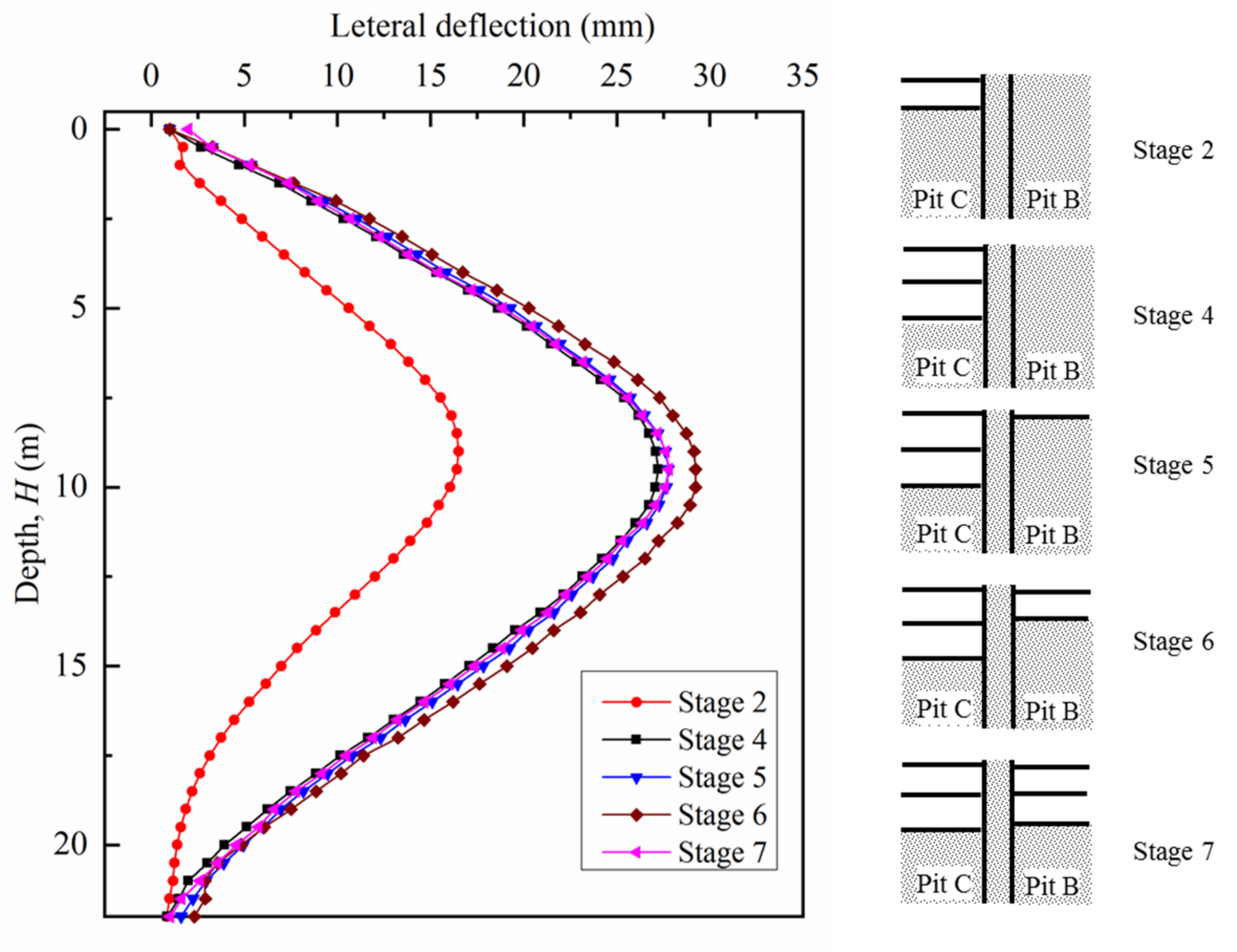
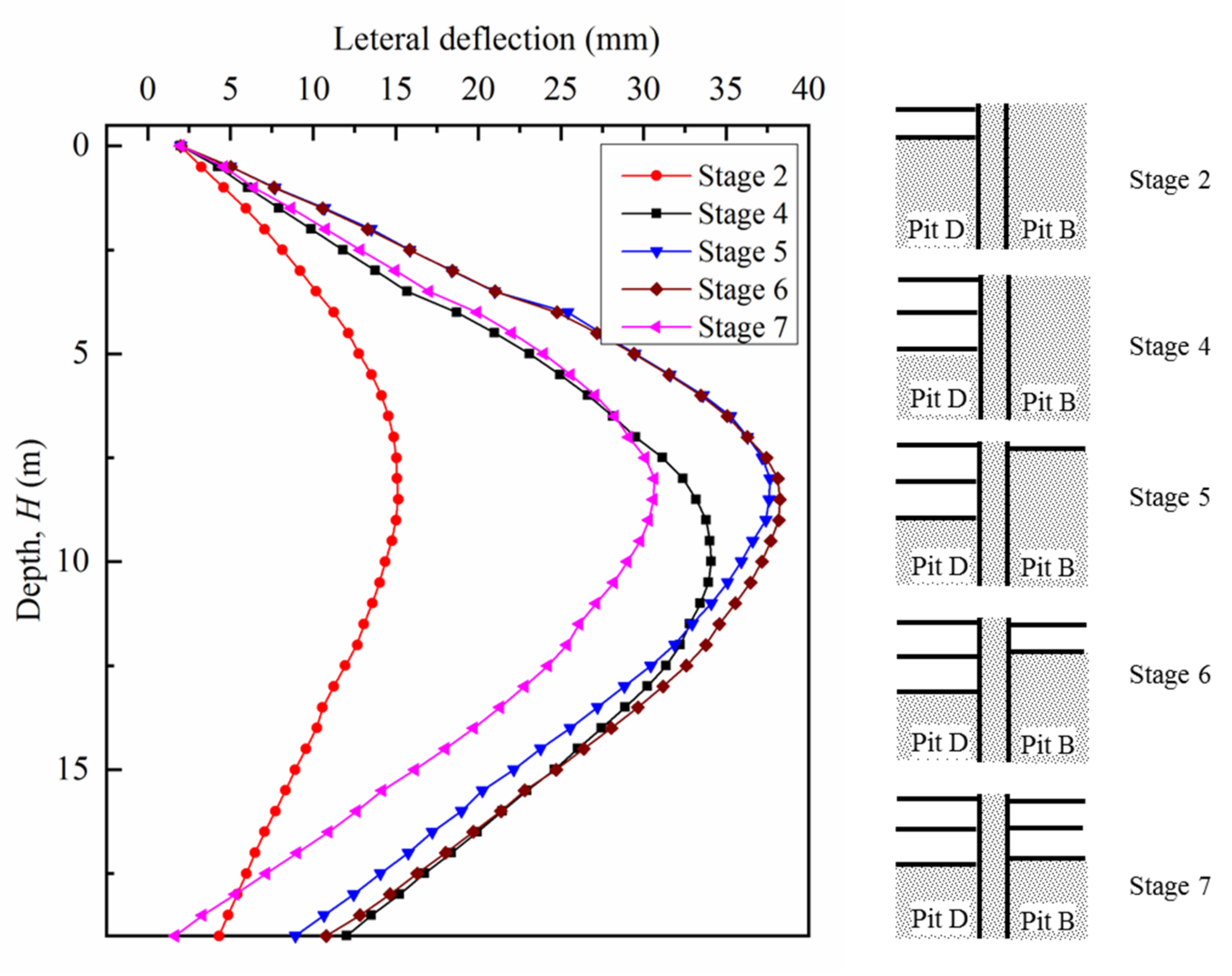
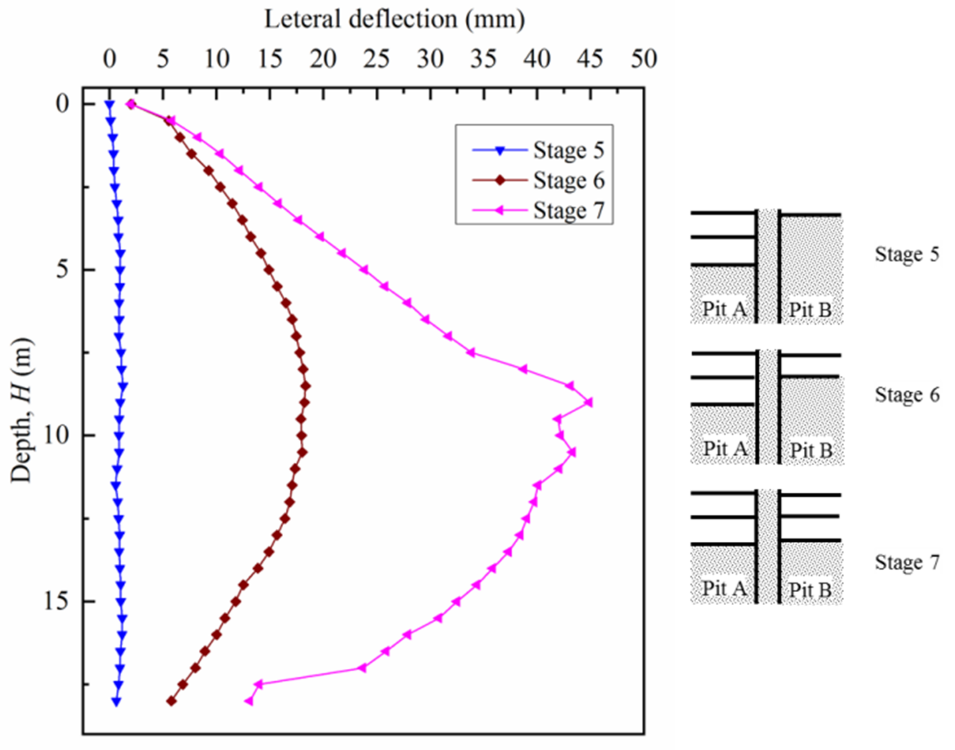
Figure 8, Figure 9, Figure 10 and Figure 11 plot the lateral deflections of the enclosure pile, and four typical monitoring points (i.e., CX5 in pit A, CX26 in pit D, CX28 in pit C, and CX9 in pit B) were selected. Among them, the measuring points within foundation pit A, C, and D (i.e., CX5, CX28, and CX26) were next to foundation pit B. It can be seen from Figure 8, Figure 9, Figure 10 and Figure 11 that the excavation of the foundation pit caused the lateral deformation of the retaining pile towards the foundation pit. With the excavation of the foundation pit, the lateral displacement of the retaining pile also increased, and the position of the maximum lateral displacement went deeper, which was near the excavation surface. This was mainly caused by the increase in the active earth pressure behind the retaining pile due to the excavation and unloading of earth pressure in the foundation pit. During stage 2 and stage 4, the second and third layers of pits A, C, and D were excavated. Because of the large thickness of the second and third layers of soil in area A, C, and D, and the long excavation duration, the lateral deflections of the enclosure pile increased significantly between stages 2 and 4.
It can also be seen from Figure 11 that the lateral deflections of the enclosure pile within foundation pit B barely changed during the excavation of foundation pits A, C, and D, which indicates that the excavation of the adjacent foundation pit had little effect on the lateral deflections of the enclosure pile of the unexcavated foundation pit. Figure 8, Figure 9 and Figure 10 also illustrate that during the excavation of foundation pit B, the lateral displacement of the retaining piles of foundation pits A, C, and D close to foundation pit B first increased and then decreased. The reason for the increase in the lateral displacement was the creep of surrounding soil or, alternatively, the time effect of the retaining structure on the foundation pit. During the excavation of foundation pit B, the long-term exposure of foundation pits A, C, and D caused the increase in the lateral displacement of the retaining pile. But the excavation of soil in foundation pit B reduced the width of soil outside foundation pits A, C, and D, resulting in a reduction of active earth pressure acting on the retaining pile of foundations pit A, C, and D. Then, the reduction in the lateral deformation of the retaining pile was expected due to the stress release caused by adjacent excavation. A similar phenomenon can be found from the measured lateral deflections of the diaphragm wall of a group excavation in Shanghai Expo Park [18]. Since the excavation schedules were different for this study and [18] detailed comparisons at different excavation stages are impossible; thus, they are not made here. According to [18], the lateral deflections of the diaphragm walls between two adjacent excavation pits were significantly less than that of the diaphragm walls along the perimeter of the whole foundation pit group. This was, again, caused by decreased earth pressure on the lateral wall from both sides due to the excavation of the foundation group [18]. Therefore, the adoption of a foundation pit group can reasonably reduce the deflection of the wall between adjacent foundation pits based on the instruments from this study and other similar practices [18].
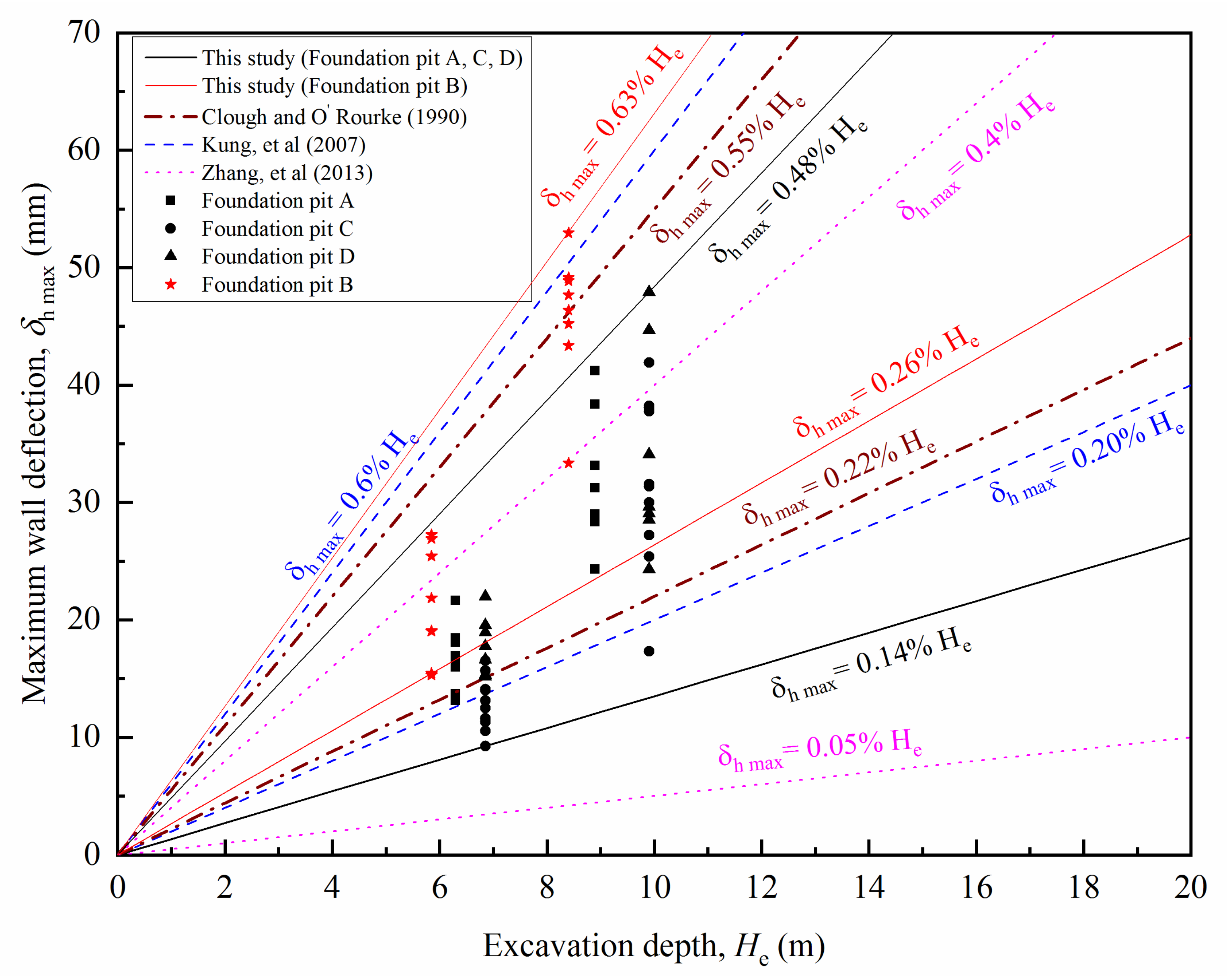
The maximum lateral deformation of the retaining pile caused by its own excavation is also shown for each foundation pit in Figure 8, Figure 9, Figure 10 and Figure 11. It can be found that the lateral displacement of foundation pit B was larger than that of foundation pits A, C, and D. The relationship between the excavation depth of foundation pits A, B, C, and D and the maximum value of the lateral displacement of each measuring point are shown in Figure 12. The upper and lower limits of the ranges from previous studies (Clough and O’Rourke 1990; Kung et al. 2007; Zhang et al. 2013) [24,25,26] are also plotted in Figure 12 for comparison. For foundation pits A, C, and D, δhm ranged from δhm = 0.14% He to δhm = 0.48% He, which is in line with those empirical relationships. This shows that the deformation of foundation pits A, C, and D conformed with other single foundation pits in Shanghai. The main reason is that foundation pits A, C, and D were not adjacent and, thus, were not affected by each other in the excavation process. For foundation pit B, δhm ranged from δhm = 0.26% He to δhm = 0.63% He, which was higher than those empirical relationships. This may be caused by the disturbance of the construction of foundation pits A, C, and D in the early stages. By controlling the excavation sequence of adjacent foundation pits, the superposition effect of the foundation pit group excavation can be well controlled. Therefore, the excavation sequence design of this foundation pit group was reasonable and effective.
5.2. Ground Settlement
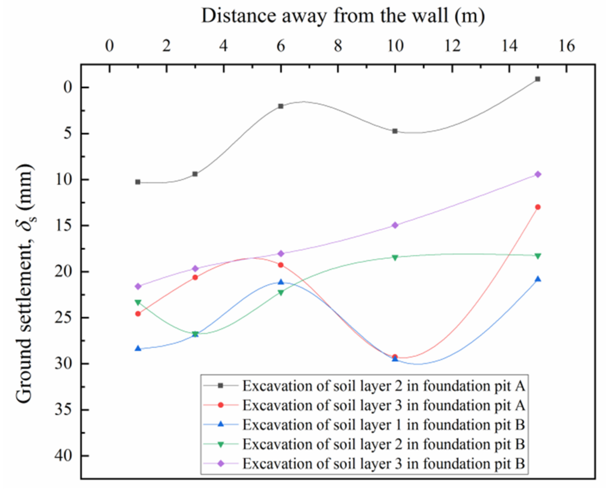
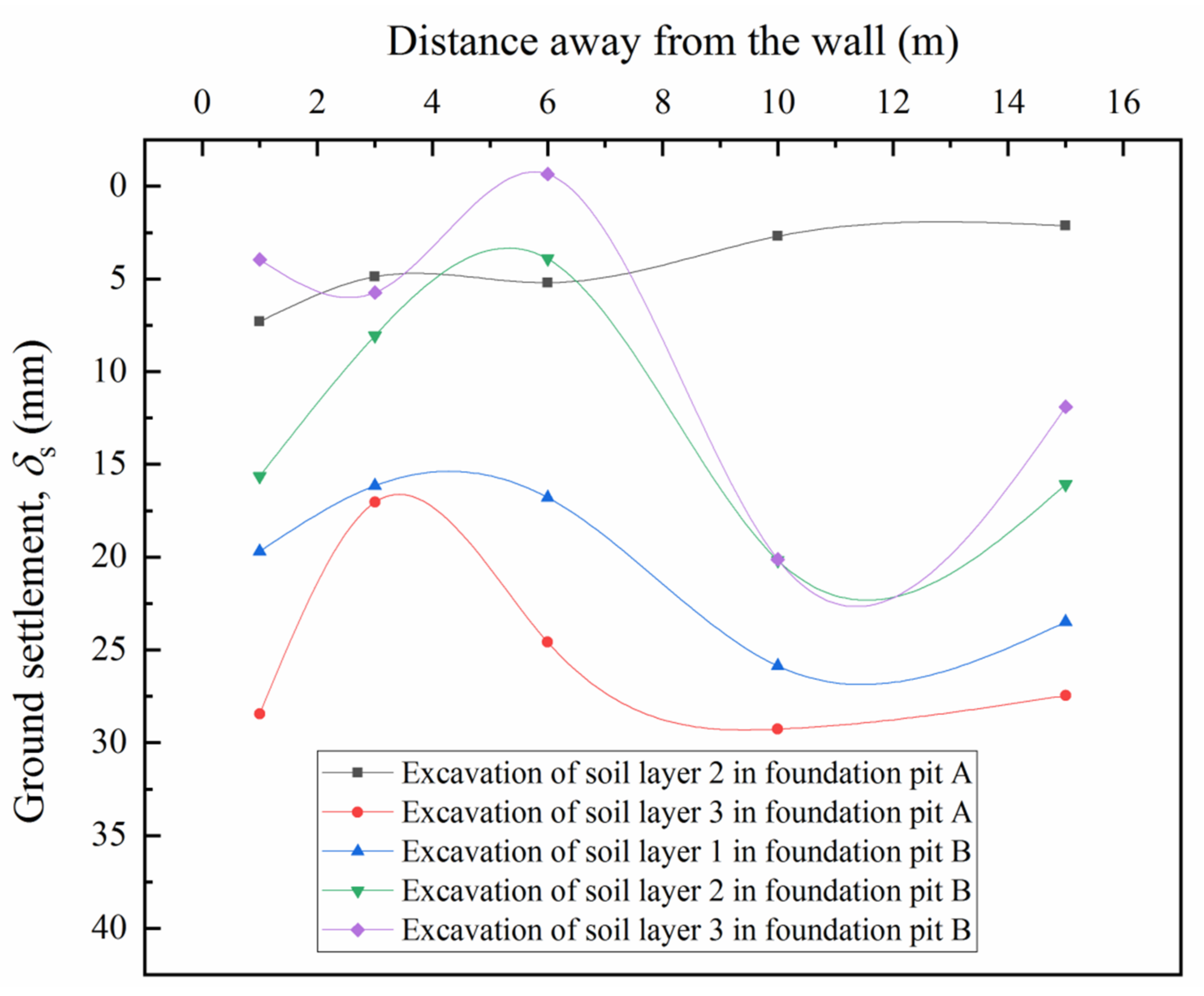
Figure 13 and Figure 14 show the distribution of ground surface settlement behind the retaining wall. The locations of JS5.1–JS5.5 and JS21.1–JS21.5 are shown in Figure 2 and Figure 3. Figure 13 and Figure 14 clearly show that the ground settlements increased with the excavation of foundation pit A. This indicates that the excavation and unloading of the soil in the pit will lead to the displacement of the outer soil into the pit. Meanwhile, it can also be found that the maximum settlement occurred approximately 10 m away from the enclosure pile during the excavation of foundation pit A. This was mainly because the friction of the retaining pile helped retain the soil near the pile and, thus, reduced the settlement of the ground surface near the retaining pile.
When foundation pit B was excavated, however, the settlements were partially offset. In other words, the excavation of B pit caused great upward movements of the surrounding ground. This may be caused by soil rebound due to the excavation and unloading of foundation pit B. When the second and third layers of foundation pit B were excavated, the excavation of foundation pits A, C, and D had been completed. Under this context, the total weight of soil in foundation pit B became the only factor that caused the deformation of the nearby ground surface. The excavation of the second and third soil layers of foundation pit B reduced the total weight of the overlying soil layer and caused the soil to rebound, which led to the reduction in the settlement on the ground surface.
5.3. Vertical Column Movement
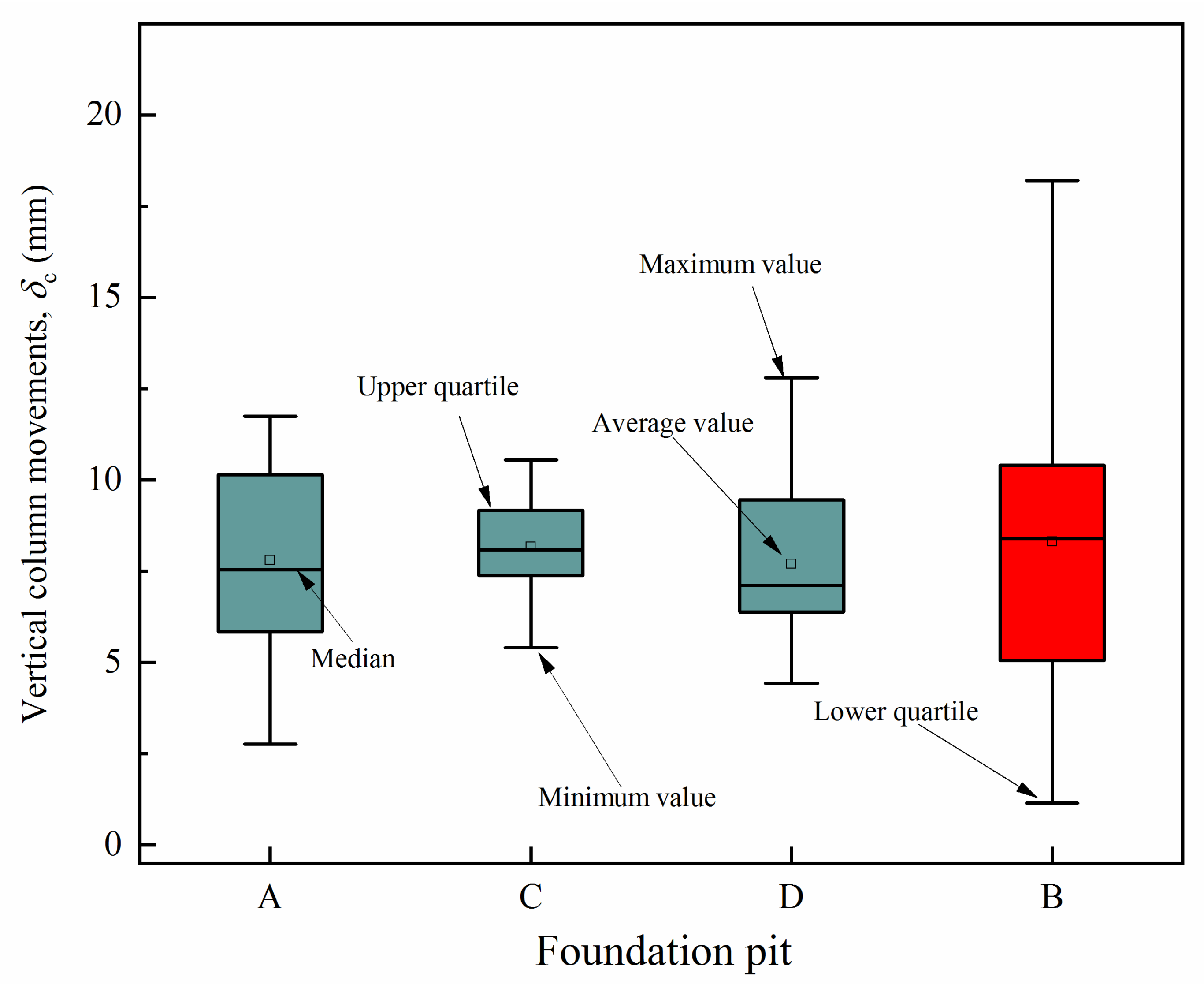
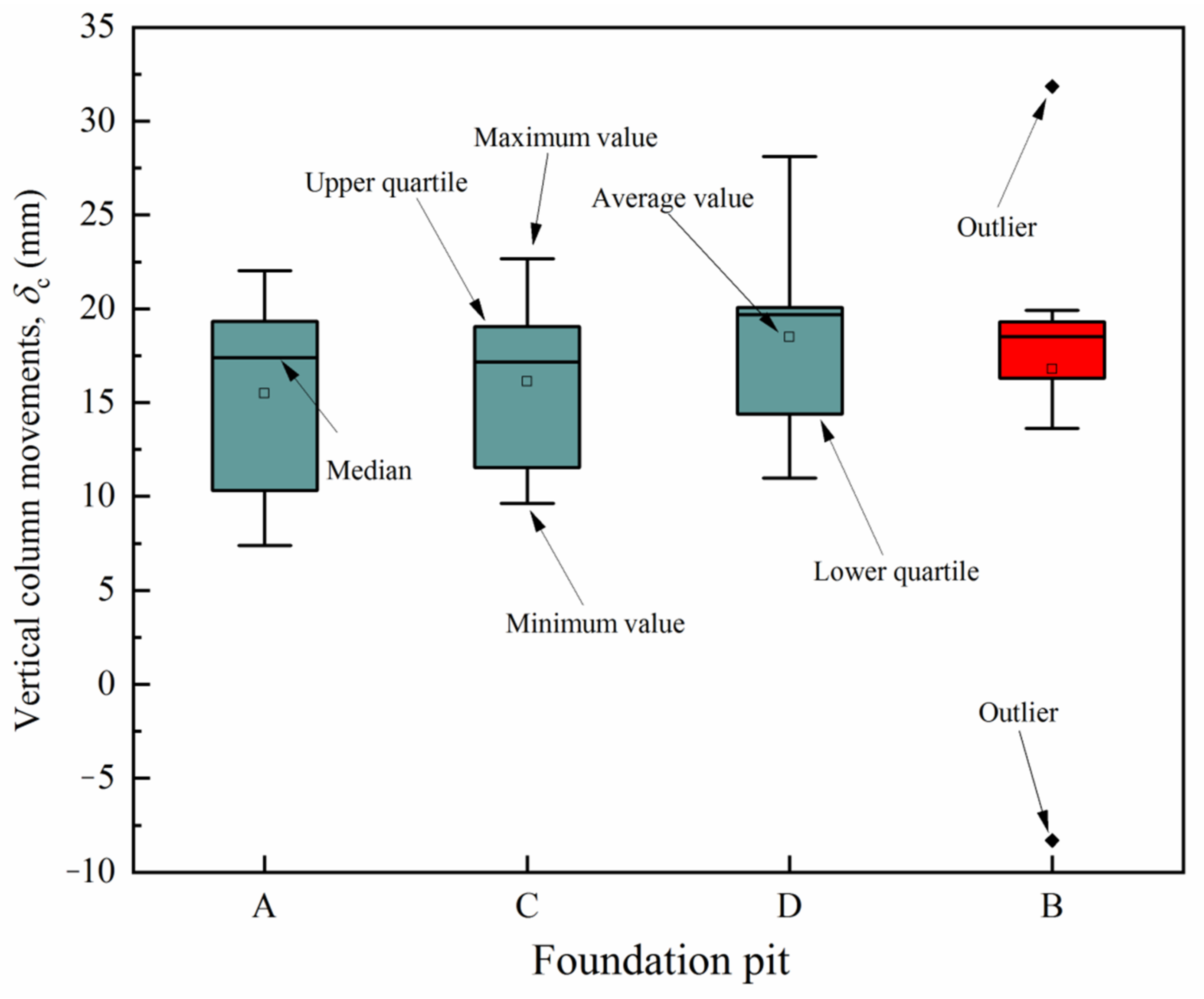
Figure 15 and Figure 16 show the statistical results of vertical column movement when the second and third layers of the foundation pits were excavated, respectively. The figures show that all the columns moved upward due to the excavation of foundation pits A, C, and D. With the excavation of the foundation pit to a deeper depth, the displacement of the column also increased, which was due to the unloading and rebound of soil inside the pit. Comparing Figure 15 and Figure 16, it can be found that the excavation of the third layer of soil caused more vertical column movement than the excavation of the second layer of soil.
In addition, the vertical column movements of pit B shared similar average values and medium values with the other three pits, indicating that the excavation of the pits A, C, and D had a negligible influence on the vertical column movements of pit B. This may be because the column piles were located inside the foundation pit and far away from foundation pits A, C, and D. In addition, the retaining structure blocked the influence of adjacent foundation pit excavation on the column, because the retaining wall mitigated the deformation of surrounding ground induced by excavation. Thus, the column piles located in the foundation pit were “isolated” by the retaining structure. Compared with the pits A, C, and D, the vertical column movements of the B pit had a larger variance. This should be because, apart from the unloading caused by the excavation of the foundation pits A, C, and D, the construction activities of foundation pit B also influenced the performance of foundation pit B significantly. The later excavated foundation pit was affected by the longer construction activities.
6. Conclusions
A foundation pit group consisting of four foundation pits was systematically investigated in this paper. The lateral deflections of the enclosure pile, the ground settlement, and the vertical column movement were analyzed via field measurements, and the following conclusions were drawn:
- Excavation of foundation pit B reduced the width of soil outside foundation pit A, C, and D, resulting in a reduction in the active earth pressure acting on the retaining pile of foundation pits A, C, and D. Thus, the lateral deformation of the retaining pile decreased due to the stress release of the lateral earth pressure;
- For foundation pits A, C, and D, δhm ranged from δhm = 0.14% He to δhm = 0.48% He, which is in line with those empirical relationships. For foundation pit B, δhm ranged from δhm = 0.26% He to δhm = 0.63% He, which is higher than those empirical relationships;
- The excavation effect in the foundation pit group was the interaction of the foundation pits with the different excavation sequences. Excavation of the adjacent foundation pit had little effect on the unexcavated foundation pit. However, the post-excavation foundation pit had a significant impact on the excavated foundation pit;
- The superposition effect of group excavation can be effectively diminished by controlling the deformation of a single foundation pit and blocking the superposition and transmission path of foundation pit deformation. Reasonable excavation sequences, such as excavation of adjacent foundation pits at different times, may reduce the superposition effect.
Author Contributions
Conceptualization, S.C. and F.L.; methodology, J.C.; software, S.C.; formal analysis, F.L.; investigation, J.C.; resources, S.C.; data curation, S.C.; writing—original draft preparation, J.C., S.C.; writing—review and editing, F.L. All authors have read and agreed to the published version of the manuscript.
Funding
This research received no external funding.
Institutional Review Board Statement
Not applicable.
Informed Consent Statement
Not applicable.
Data Availability Statement
The data are contained within the article.
Acknowledgments
The authors wish to express their gratitude to the anonymous reviewers whose constructive comments helped to improve the overall quality of this paper.
Conflicts of Interest
The authors declare no conflict of interest.
References
- Tan, Y.; Wang, D.L. Characteristics of a large-scale deep foundation pit excavated by central-island technique in Shanghai soft clay. Part I: Bottom-up construction of the central cylindrical shaft. J. Geotech. Geoenviron. Eng. 2013, 139, 1875–1893. [Google Scholar] [CrossRef]
- Tan, Y.; Wang, D.L. Characteristics of a large-scale deep foundation pit excavated by central-island technique in Shanghai soft clay. Part II: Top-down construction of the peripheral rectangular pit. J. Geotech. Geoenviron. Eng. 2013, 139, 1894–1910. [Google Scholar] [CrossRef]
- Wang, J.H.; Xu, Z.H.; Wang, W.D. Wall and ground movements due to deep excavations in Shanghai soft soils. J. Geotech. Geoenviron. Eng. 2010, 136, 985–994. [Google Scholar] [CrossRef]
- Gör, M.; Taher, N.R.; Aksoy, H.S.; Awlla, H.A. Effect of Geogrid Inclusion on the Slope Stability. In Proceedings of the V-International European Conference on Interdisciplinary Scientific Research, Valencia, Spain, 28–29 January 2022; pp. 275–286. [Google Scholar]
- Özbey, I.; Gör, M. A Study on Well Foundations: Well Foundation Analyzes for Attached Buildings. In Proceedings of the IV-International Icontech Symposium on Innovative Surveys in Positive Sciences, Adana, Turkey, 18–19 July 2021; pp. 248–261. [Google Scholar]
- Gör, M. Evaluation of a Mass Movement Occurred after Slope Excavation. In Proceedings of the 7th International Zeugma Conference on Scientific Research, Gaziantep, Turkey, 21–23 January 2022; pp. 69–84. [Google Scholar]
- Tan, Y.; Wei, B. Observed behaviors of a long and deep excavation constructed by cut-and-cover technique in Shanghai soft clay. J. Geotech. Geoenviron. Eng. 2012, 138, 69–88. [Google Scholar] [CrossRef]
- Liu, G.B.; Ng CW, W.; Wang, Z.W. Observed performance of a deep multistrutted excavation in Shanghai soft clays. J. Geotech. Geoenviron. Eng. 2005, 131, 1004–1013. [Google Scholar] [CrossRef]
- Tan, Y.; Li, X.; Kang, Z.J.; Liu, J.X.; Zhu, Y.B. Zoned excavation of an oversized pit close to an existing metro line in stiff clay: Case study. J. Perform. Constr. Facil. 2015, 29, 04014158. [Google Scholar] [CrossRef]
- Finno, R.J.; Arboleda-Monsalve, L.G.; Sarabia, F. Observed performance of the one museum park west excavation. J. Geotech. Geoenviron. Eng. 2015, 141, 04014078. [Google Scholar] [CrossRef]
- Shi, J.; Liu, G.B.; Huang, P.; Ng, C.W.W. Interaction between a large-scale triangular excavation and adjacent structures in Shanghai soft clay. Tunn. Undergr. Space Technol. 2015, 50, 282–295. [Google Scholar] [CrossRef]
- Hashash YM, A.; Levasseur, S.; Osouli, A.; Finno, R.; Malecot, Y. Comparison of two inverse analysis techniques for learning deep excavation response. Comput. Geotech. 2010, 37, 23–333. [Google Scholar] [CrossRef]
- Yang, Z.K.; Chen, Y.L.; Azzam, R.; Yan, C. Performance of a top-down excavation in shanghai: Case study and numerical exploration. Eur. J. Environ. Civ. Eng. 2021. [Google Scholar] [CrossRef]
- Yang, Z.K.; Chen, Y.L.; Yan, C.; Azzam, R. Numerical Evaluation of Isolation Walls in Modifying Excavation-Induced Displacement Field. Arab. J. Sci. Eng. 2022. [Google Scholar] [CrossRef]
- Liu, Y.; Xiang, B.H.; Fu, M.F. Observed performance of a large-scale deep triangular excavation in Shanghai soft clays. Geotech. Geol. Eng. 2019, 37, 2791–2809. [Google Scholar] [CrossRef]
- Dan, K.; Sahu, R.B. Estimation of ground movement and wall deflection in braced excavation by minimum potential energy approach. Int. J. Geomech. 2018, 18, 04018068. [Google Scholar] [CrossRef]
- Lim, A.; Ou, C.Y. Stress paths in deep excavations under undrained conditions and its influence on deformation analysis. Tunn. Undergr. Space Technol. 2017, 63, 118–132. [Google Scholar] [CrossRef]
- Li, M.G. Deformation Behavior of Adjacent Retaining Walls in Group Excavation. Ph.D. Thesis, Shanghai Jiao Tong University, Shanghai, China, 2016. (In Chinese). [Google Scholar]
- Zhang, H.B. Environmental Impact Induced by Excavation Group and Deformation Control. Ph.D. Thesis, Shanghai Jiao Tong University, Shanghai, China, 2016. (In Chinese). [Google Scholar]
- Chen, J.J.; Zhu, Y.F.; Li, M.G.; Wen, S.L. Novel excavation and construction method of an underground highway tunnel above operating metro tunnels. J. Aerosp. Eng. 2015, 28, A4014003. [Google Scholar] [CrossRef]
- Wang, J.H.; Chen, J.J.; Li, M.G. Concept and characters of deep excavation groups in urban underground space development. Jpn. Geotech. Soc. Spec. Publ. 2016, 2, 1559–1562. [Google Scholar] [CrossRef] [Green Version]
- Dai, B.; Hu, G.; Wang, H.S. Analysis and practice of influence of synchronous excavation of adjacent foundation pits in Shanghai area. Chin. J. Geotech. Eng. 2021, 43, 129–132. (In Chinese) [Google Scholar]
- Chen, H.H.; Li, J.P.; Li, L. Performance of a zoned excavation by bottom-up technique in Shanghai soft soils. J. Geotech. Geoenviron. Eng. 2018, 144, 05018003. [Google Scholar] [CrossRef]
- Clough, G.W.; O’Rourke, T.D. Construction induced movements of in-situ walls. In Conference on Design and Performance of Earth Retaining Structures; Geotechnical Special Publication No. 25; ASCE: New York, NY, USA, 1990; pp. 439–470. [Google Scholar]
- Kung, G.T.C.; Juang, C.H.; Hsiao, E.C.L.; Hashash, Y.M.A. Simplified model for wall deflection and ground-surface settlement caused by braced excavation in clays. J. Geotech. Geoenviron. Eng. 2007, 133, 731–747. [Google Scholar] [CrossRef]
- Zhang, D.F.; Tong, L.Y.; Liu, S.Y.; Gao, X.N.; Lou, C.B. Deformation behavior of supporting structures of deep excavations in Suzhou subway line 1. Chin. J. Underground Space Eng. 2013, 9, 1961–1965. [Google Scholar]
Figure 1.
Satellite view of the proposed site plan.

Figure 2.
Site plan of the project site and instrumentation layout (foundation pit A).

Figure 3.
Site plan of the project site and instrumentation layout (foundation pit B).

Figure 4.
Site plan of the project site and instrumentation layout (foundation pit C).

Figure 5.
Site plan of the project site and instrumentation layout (foundation pit D).

Figure 6.
Excavation of soil layer 2 and casting the strut (level 2).

Figure 7.
Excavation of soil layer 3.

Figure 8.
Lateral wall deflections of CX5 for the various excavation stages.

Figure 9.
Lateral wall deflections of CX26 for the various excavation stages.

Figure 10.
Lateral wall deflections of CX28 for the various excavation stages.

Figure 11.
Lateral wall deflections of CX9 for the various excavation stages.


Figure 13.
Ground settlements along the distance from the wall (JS5.1–JS5.5).

Figure 14.
Ground settlements along the distance from the wall (JS21.1–JS21.5).

Figure 15.
Vertical column movement (excavation of the second layer of soil) (Green box: peripheral foundation pit; Red box: intermediate foundation pit).
Figure 15.
Vertical column movement (excavation of the second layer of soil) (Green box: peripheral foundation pit; Red box: intermediate foundation pit).

Figure 16.
Vertical column movement (excavation of the third layer of soil) (Green box: peripheral foundation pit; Red box: intermediate foundation pit).
Figure 16.
Vertical column movement (excavation of the third layer of soil) (Green box: peripheral foundation pit; Red box: intermediate foundation pit).


Table 1.
Foundation pit details.
| Foundation Pit | A | B | C | D |
|---|---|---|---|---|
| Area (m2) | 9334 | 8838 | 8241 | 12,331 |
| Perimeter (m) | 372 | 367 | 345 | 437 |
| Depth (m) | 8.9 | 8.4 | 9.9 | 9.9 |
| Number of main structure floors | −2~11 | −2~12 | −2~15 | −2~13 |
Table 2.
Physical and mechanical parameters of soil layers.
| No. | Soil Type | Unit Weight, γ (kN/m3) | Cohesion, c (kPa) | Friction Angle, φ (°) | Permeability Coefficient, kv (cm/s) |
|---|---|---|---|---|---|
| ➁ | Silty clay | 18.5 | 19 | 18 | 4.36 × 10⁻⁶ |
| ➂ | Muddy silty clay | 17.4 | 14 | 17 | 5.70 × 10⁻⁶ |
| ➃ | Muddy clay | 16.8 | 12 | 11 | 1.28 × 10⁻⁶ |
| ➄2-1 | Sandy clay | 18.2 | 4 | 30 | 3.54 × 10⁻⁶ |
| ➄2-2 | Silty clay | 18.0 | 7 | 17 | 3.42 × 10⁻⁶ |
Table 3.
Detailed construction schedule.
| Stage | Event | Date | |
|---|---|---|---|
| 1 | Excavation of soil layer 1 of foundation pits A, C, and D Casting the strut (level 1) of foundation pits A, C, and D | 3 March 2019 | 17 March 2019 |
| 2a | Excavation of soil layer 2 of foundation pits A, C, and D | 18 March 2019 | 29 March 2019 |
| 2b | Casting the strut (level 2) of foundation pits A, C, and D | ||
| 3 | Excavation of soil layer 1 of foundation pit B | 18 March 2019 | 24 March 2019 |
| 4a | Excavation of soil layer 3 of foundation pits A, C, and D | 30 March 2019 | 13 May 2019 |
| 4b | Casting the base slab of foundation pits A, C, and D | ||
| 5 | Casting the strut (level 1) of foundation pit B | 7 May 2019 | 13 May 2019 |
| 6a | Excavation of soil layer 2 of foundation pit B | 19 May 2019 | 23 May 2019 |
| 6b | Casting the strut (level 2) of foundation pit B | ||
| 7a | Excavation of soil layer 3 of foundation pit B | 16 June 2019 | 30 July 2019 |
| 7b | Casting the base slab of foundation pit B | ||
Publisher’s Note: MDPI stays neutral with regard to jurisdictional claims in published maps and institutional affiliations. |
© 2022 by the authors. Licensee MDPI, Basel, Switzerland. This article is an open access article distributed under the terms and conditions of the Creative Commons Attribution (CC BY) license (https://creativecommons.org/licenses/by/4.0/).
Share and Cite
MDPI and ACS Style
Chen, S.; Cui, J.; Liang, F. Case Study on the Deformation Coupling Effect of a Deep Foundation Pit Group in a Coastal Soft Soil Area. Appl. Sci. 2022, 12, 6205. https://0-doi-org.brum.beds.ac.uk/10.3390/app12126205
AMA Style
Chen S, Cui J, Liang F. Case Study on the Deformation Coupling Effect of a Deep Foundation Pit Group in a Coastal Soft Soil Area. Applied Sciences. 2022; 12(12):6205. https://0-doi-org.brum.beds.ac.uk/10.3390/app12126205
Chicago/Turabian StyleChen, Shangrong, Jifei Cui, and Fayun Liang. 2022. "Case Study on the Deformation Coupling Effect of a Deep Foundation Pit Group in a Coastal Soft Soil Area" Applied Sciences 12, no. 12: 6205. https://0-doi-org.brum.beds.ac.uk/10.3390/app12126205
Note that from the first issue of 2016, this journal uses article numbers instead of page numbers. See further details here.