
Distance Assessment by Object Detection—For Visually Impaired Assistive Mechatronic System


Institute of Solid Mechanics, Romanian Academy, 010141 Bucharest, Romania
*
Author to whom correspondence should be addressed.
Appl. Sci. 2022, 12(13), 6342; https://0-doi-org.brum.beds.ac.uk/10.3390/app12136342
Submission received: 12 May 2022
/
Revised: 17 June 2022
/
Accepted: 20 June 2022
/
Published: 22 June 2022
(This article belongs to the Special Issue New Trends in Robotics, Automation and Mechatronics (RAM))
Abstract
:Techniques for the detection and recognition of objects have experienced continuous development over recent years, as their application and benefits are so very obvious. Whether they are involved in driving a car, environment surveillance and security, or assistive living for people with different disabilities, not to mention advanced robotic surgery, these techniques are almost indispensable. This article presents the research results of a distance assessment using object detection and recognition techniques. The first is a new technique based on low-cost photo cameras and special sign detection. The second is a classic approach based on a LIDAR sensor and an HQ photo camera. Its novelty, in this case, consists of the concept and prototype of the hardware subsystem for high-precision distance measurement, as well as fast and accurate object recognition. The experimentally obtained results are used for the motion control strategy (directional inverse kinematics) of the robotic arm (virtual prototype) component in special assistive devices designed for visually impaired persons. The advantages of the original technical solution, experimentally validated by a prototype system with modern equipment, are the precision and the short time required for the identification and recognition of objects at relatively short distances. The research results obtained, in both the real and virtual experiments, stand as a basis for the further development of the visually impaired mechatronic system prototype using additional ultrasonic sensors, stereoscopic or multiple cameras, and the implementation of machine-learning models for safety-critical tasks.
1. Introduction
Avoiding obstacles to avoid collision and choosing the best walking trajectories for people with visual disabilities is currently an important concern. From another point of view, helping people with health problems using complex surgical interventions is a delicate mission. It needs advanced techniques for object recognition and the avoidance of interference from different types of obstacles (patient organs, blood vessels, nerves) as well as the targeted end motion of surgical tools. The existence of systems that allow the obtaining of real-time information on the environment has also led to the development of methods for interpreting this information. A special field has emerged in recent years through diligent research, namely, the detection and recognition of objects on the motion trajectory of mechatronic systems.
In order to work in a human-like, unstructured environment, mechatronic and robotic systems need an extremely large amount of different information and high-powered software analysis. Through the digital images captured by the visual perception subsystem, these systems must identify the characteristics of the objects in the work environment and recognize their type. The processing of information related to complex images and the correlation with the data of the other subsystems determine the actions necessary to achieve the required objective, but only after the correct and accurate recognition of the object.
People with visual impairments, in addition to moving in closed or open spaces, need to carry out daily activities that, in most cases, require the recognition of environmental objects. Some issues need to be taken into account when it comes to integrating visually impaired people into society. The participation of people with visual disabilities in social life means creating a specific framework and appropriate devices (devices specific to the activities carried out and equipped with sensors that allow data collection for spatial orientation, object recognition, location, etc.) that would enable them to carry out activities similar to those of any other person with no disabilities.
This is one of the reasons why environmental recognition applications have entered the field of assistive systems for visually impaired persons (VIPs). VIPs are oriented, aided by technology, towards a more complete and accurate understanding of the environment, obtaining new abilities to communicate properly with other people.
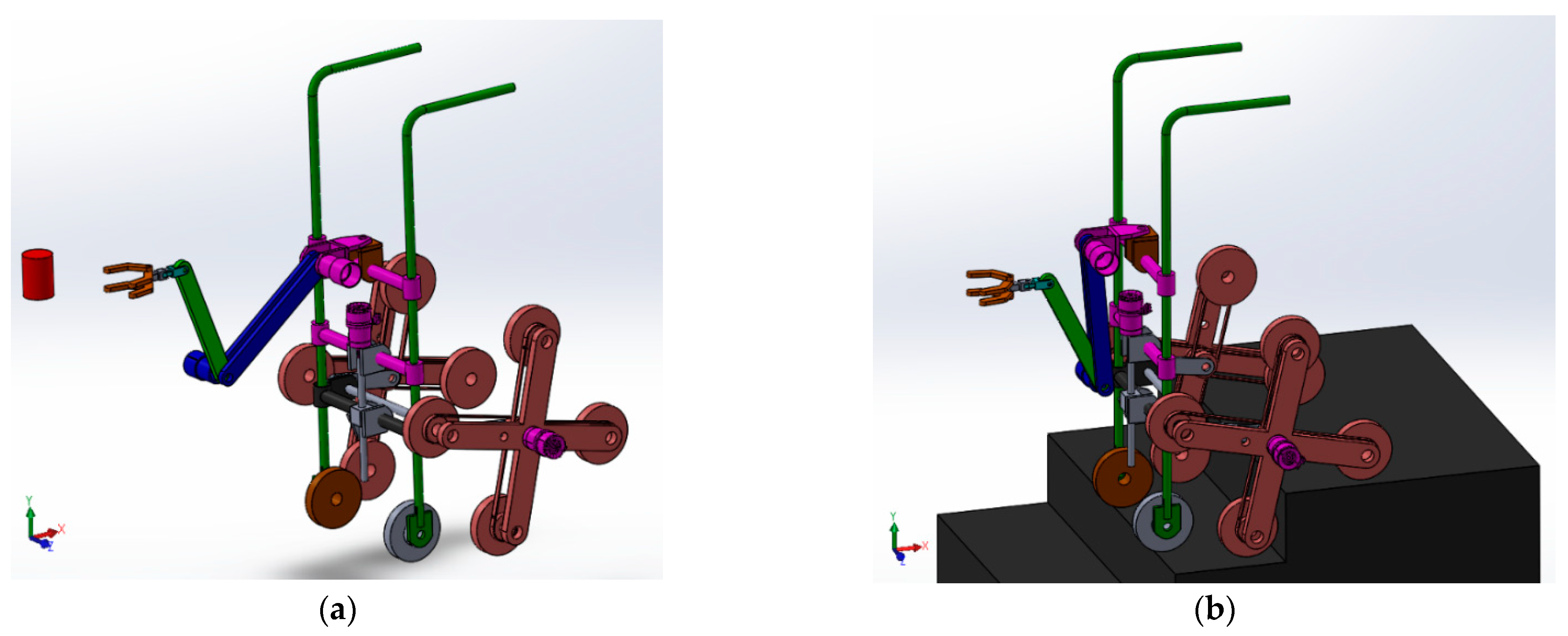
The concept and design (by the authors) of a special device aimed to assist VIPs with their mobility are shown in Figure 1. The device enables the user to detect and grab objects and avoid obstacles, and provides guidance when the user walks down alleys and narrow spaces, as well as when climbing the stairs (up and down). In this study, the device is called a VIPs-Walker.
The VIPs-Walker system is designed as a modular structure (with a voice assistance module and a haptic module), and is intended to be used by both visually impaired people and those with multiple disabilities (stability issues that require support while walking). The user’s comfort is enhanced by the device’s motion system (electric motor), as the VIP only needs to follow the device and its feedback.
In recent years, various studies have focused on devices with applications for choosing the correct routes using GPS coordination, assessing distances from objects met on the road, detecting and recognizing objects in front of the device, etc.
Some of the devices have already been the subject of government assistance programs in Romania, and some programs allow visually impaired people to purchase such devices with a subsidy in the form of a support voucher after their medical documents have been examined by a medical commission. The devices belong to different categories, including smart canes or white canes and portable devices that can be attached to the frame of the user’s glasses.
This article presents the research concept and the results of the distance assessment of a new, customized object detection and recognition technique.
The first approach is a new method based on low-cost photo cameras (from a mobile phone) used for special sign detection and distance assessment. This method is intended to be available for ordinary visually impaired people who, most of the time, do not have a good financial situation.
Another focus of first approach includes the implementation in applications for surgical robots. Surgery that is coordinated and assisted by robotics is also a reality today. Observing areas undergoing treatment, recognizing areas between organs and areas affected by various types of disease, and measuring the size of and distance between tissues inside the body using non-invasive methods represent important requirements for mechatronic systems used in the medical field. Through high-performance visualization systems, with the possibility of presentation through augmented reality, colorists, transparency, sectioning, focusing, contrast, etc., robotic systems have acquired a new sense of environmental perception [1,2,3].
The second approach is based on an RPLIDAR sensor and HQ camera, designed to work as an innovative hardware subsystem, which enables fast and accurate object recognition as well as high-precision distance measurement. Because of its high-performance components, this system is relatively expensive, but stands as a very good solution when high-precision results need to be obtained.
The system designed for this research is an innovative mobile robotic platform equipped with an HQ monocular visual subsystem, LIDAR-type scanning sensor (“light detection and ranging” or “laser imaging, detection and ranging”) and a Jetson Nano development kit. This structure can obtain extra and fast information and accurate knowledge of the environment, as well as the recognition of its objects, facilitating the execution of the necessary motions in safe conditions. At the time of this research, no studies were identified in the specific literature that included the hardware combination of the Raspberry Pi HQ camera with an IMX477 sensor and the RPLIDAR A3 scanner.
The results obtained (experimentally) by each of the abovementioned items can be used for the elaboration of the strategies for the motion control of mechatronic systems used in healthcare and assistive living, specifically the robotic arm of the VIPs-Walker.
This paper is structured as follows. Section 2 outlines a review of some recent research on mechatronic structures, methods, algorithms, and perceptual equipment. Section 3 highlights the materials and methods used. Section 4 provides information on the experimental results obtained in the real environment and the results of the simulation of the motion of the VIPs-Walker arm in order to evaluate the strategy and dynamics of grabbing an object. The final part of the article presents discussions and observations on the methods and equipment used in Section 5, as well as the conclusions of the research in Section 6.
2. State of the Art
Recognizing subjects from images obtained with cameras is quite a new domain for researchers. Computer visualization and computer image processing have given rise to the information technology subdomain. By studying the homogeneity of colors, the distribution of color pattern components, the spatial relationships between the observed areas, color grouping, and the boundaries between color areas, we found certain relationships between the coloristics that exist in images and the possible existing objects in the frame [4].
Over time, techniques have been developed to enable the recognition of persons and facial recognition [5], for tracking moving objects, counting vehicles on surveillance cameras and obtaining information on their registration number [6], for recognizing activity [7], etc.
There are two major trends in the development of object recognition methods, depending on the technology used: systems based on the function for visualization of the environment (cameras/video), and systems without visualization of the environment (IR sensors, laser, ultrasonic, Bluetooth, or GPS) [8]. Such systems are included in practical applications in many fields, but two are particularly distinct: applications in the field of freight and passenger transport for self-driving cars, and in the medical field for the assistance of people with visual impairments.
The field of self-driving transport systems is a daily reality. A method of assessing the distance from obstacles to autonomous systems using video cameras is presented in [9]. Methods for recognizing objects from information obtained with the help of video cameras are few: from methods of the intuitive processing of still or moving images with the help of technologies based on neural networks [10], to methods that use parallel systems of multiple recognition for less error. The key task is to enable the vehicle to understand the environment correctly and make real-time decisions [11]. A multitude of sensors can be used simultaneously: video cameras, LIDAR lasers, radar, inertial measurement units (IMU), global satellite navigation (GPS), etc.
Objects existing in the working environment of the mechatronic and robotic systems must be detected and evaluated as a shape and a name, sometimes only recognized by an area or portion, classified according to the templates in the existing databases [12] and possibly corrected parametrically.
Object recognition is used by artificial intelligence systems for machine learning through appropriate algorithms and software based on real-world data in order to improve their own performance through experience and for advanced deep learning [13,14,15], which is performed using advanced methods that often include artificial neural networks with multiple layers to facilitate the robotic system automatic identification in the future of all 3D material elements encountered.
From a technical point of view, the visual perception equipment used in the research includes simple cameras, high-performance HQ cameras, infrared cameras, and IMU (inertial measurement units) or LIDAR sensors [16,17] to enhance contour and shape recognition. There are many studies in the literature that incorporate the method with stereo cameras [18,19] or with multiple cameras [20], which “attack” the object from several angles in order to improve its descriptive technical parameters.
Among the parameters analyzed in the research are depth, overall size, image distortion [21], and the accuracy of estimating the position of the object.
In order for the intelligent system to “see”, experimental applications based on digital images are focused on the identification of moving deformable objects, door openings, the detection of vegetables and fruits [22], the avoidance of obstacles, and the sorting of construction gravel aggregates.
Several interconnected modules, including the visual perception subsystem and the learning subsystem, are required to control robotic systems. The stability of the activities of these systems is based on the detection and recognition of objects. The hardware binocular structure developed in [23] merges information from a high-resolution color camera and a low-resolution depth camera.
In [24], Cao et al. show an algorithm for tracking 3D objects, manually selected, using the patch model, with depth as the main parameter in a new, robust method based on Gauss’s theory with two probabilistic components and on the recovery of occlusions. As a result of the experiments performed with the mobile binocular camera stereo perception subsystem, the increased efficiency for deformable targets was obtained in relation to similar requests made recently. It is worth noting the idea of using such a model for deformable targets for the first time.
Less research has been conducted in the field of assistive systems for people with disabilities, but given the medical importance of the field, these should not be neglected.
A system designed for blind individuals has shown that during the use of the BrainPort sensor, by the electrotactile presentation of the visual image, strong activity appears in the areas of the primary visual cortex—areas that, before its use, were not active. As an application of this sensor, it can be noted that it can be adapted as part of a pacifier for blind babies or it can be used together with a camera located on a pair of glasses to detect the shape of objects [25]. The circuit provides a specialized brain–computer interface (BCI) software interface. The information is captured by the camera and transmitted to the touch device. A tactile vision substitution system (TVSS) translates the visual input, usually from a video camera, to the output of a tactile stimulation matrix. With the help of digital image processing techniques, the most significant features of the image can be extracted and then offered as a sensation to visually impaired people [26].
A system for the visually impaired, called OrCam MyEye, can help these people read black and white information. In order for this device to be able to read, the point at which the user begins to read must be indicated, and this presupposes that the person perceives the light and distinguishes some signs. Another drawback is that it cannot appreciate the distance between the object and the interlocutor [27].
In [28], the authors partially designed and simulated an innovative concept of a dedicated integrated system (DIS) using software adapted to the needs of computer work (Smart Individual Security and Assistance Application—SI-SAA) and through an intelligent mobile mechatronic system for the safe movement of visually impaired students in enclosed spaces, such as classrooms. The failure to identify obstacles in the workplace in a timely manner puts their health at risk, and in some cases, endangers the lives of people with visual impairments. The advantages offered by this solution refer to the computer-learning activity through the interface with voice support in Romanian, the realization of the topographic plans of the classroom, the identification of obstacles, and the provision of essential information for their movements.
An obstacle avoidance system with the help of a video camera that allows the evaluation of distances has been developed by Saputra [29]. The proposed system has shown promising results, as it detects obstacles in any direction from the assisted subject. Portable systems for assisting people with disabilities have even been developed based on images obtained from a simple mobile phone. Pogi and Mattoccia [30] developed such a system that has given very promising results, with the only disadvantage being the limitation of the recognized categories of objects, but adapted for machine learning (ML) methods, the system can be further developed.
Some outdoor assistance systems for people with disabilities are based on the global positioning system (GPS), which allows the correct assessment with an error of 1 m of the position of the subject’s location on the maps used and the speeds of travel in any direction can change [31].
One article that studies a portable system for detecting objects and estimating distance using ultrasonic sensors is [32]. When a person approaches an obstacle, the sensors can only detect the existence of the object in front of the user and, using a piezoelectric buzzer, the state is announced through the sound system of the device.
Another article in which the authors studied an ultrasonic radar system that would also allow the identification of moving objects is [33]. The researchers were able to simultaneously evaluate several parameters: the distance from the object, the direction of travel, its speed, and even the shape of the observed object.
For complex objects with multiple geometric configurations in paper [34], the researchers developed an advanced system with the help of a high-performance ultrasonic sonar from Polaroid with which it was possible to recognize objects using various information extracted from the echo waves of the sonar, and having a database with different configurations of searched objects. The conclusion was that ultrasonic sonar can be used as a viable system for real-time object recognition in robotics or other applications.
The coverage of the field to be studied, depending on the situations in practice, can be done with the help of in-line scanning cameras—cameras that are especially suitable for applications that require both high speeds and high image quality. A line-scan camera reads image data one at a time. It detects fine features such as text lines, barcodes, material characteristics, and QR codes, all of which are possible because it uses optical character recognition (OCR) techniques [35].
A special chapter on the recognition of structures by imaging methods is a specific domain of medical imaging. The methods of obtaining images in this field are based on completely different techniques from those used in common photo or video cameras. Medical imaging is based on deep tissue scanning methods using techniques that use ionizing radiation (CT or X-ray and gamma radiation), based on nuclear magnetic resonance (MRI), or photoacoustic methods based on laser radiation or ultrasound. Images are obtained using sensors that are specifically sensitive to each of these types of radiation [36,37,38,39].
Yi and Dong sought to combine different methods of object detection for greater accuracy, obtaining more types of information through the detection procedure and appropriate measurements in various work environments, thus obtaining more complete coverage of the studied field [40].
An algorithm often used by optic devices is YOLO (You Only Look Once). This algorithm is popular because of its speed and accuracy. It has been used in various applications to detect traffic signals, people, parking meters, and animals. YOLO can also be used in security systems to enforce the security in an area [41,42,43,44].
Its high performance results from multiple improvements, such as YOLOv2, YOLOv3, YOLOv4 (R-YOLOv4, LS-R-YOLOv4 based on the LIDAR sensor).
The detection and recognition systems have specialized software, with up to 2500 algorithms (for example, OpenCV—soft open source for Computer Vision). In fact, we used this software and its implemented algorithms in our research, as further evidenced.
Based on the knowledge evidenced by the cited references and, not least, based on the expertise and authors’ personal experience, two new customized ways of transforming objective reality into information (useful for visually impaired persons) were considered for distance assessment by object detection and recognition.
3. Materials and Methods
There are two innovative aspects in this research. The first consists of distance assessment using low-cost cameras based on special sign detection (not used until now). The second is the development of a customized technical solution for a perception subsystem using a laser RPLIDAR sensor and a photo camera.
Each of the abovementioned systems was independently calibrated and the results evaluated.
The research is based on the concept of the blockchain scheme for a mechatronic system (virtual prototype) designed to improve the quality of life of people with visual impairments (see Figure 2).
The collaboration of the equipment of the perception subsystem, the HQ camera and laser beam sensor, is supervised by the actuator controller that monitors the evolution of the factual situation, data fusion, route and action planning, optimization, and execution of commands so that the missions can be fulfilled.
There are some basic hypotheses considered for this research that mainly focus on the customized object detection and recognition techniques for an assistive device for visually impaired people. These hypotheses are mentioned next.
Hypothesis 1 (H1).
The software used for visualizing the environment is RViz, installed under the operating system for robots ROS Melodic, enabling work on the NVIDIA Jetson Nano platform. This was the choice due to the customized hardware system (RPLIDAR and HQ camera).
Hypothesis 2 (H2).
The authors propose the use of specially designed signs for a new technique in distance assessment.
Hypothesis 3 (H3).
There is no need for spatial consistency of the assistive devices for visually impaired people, as the possibility of receiving complex information is, in most cases, limited.The visualization study is only focused in one direction—to the detected object.
Hypothesis 4 (H4).
In the case of motion control, especially for the robotic arm of the designed assistive device, the target is to grab an object, close a window, or open a door standing in the user’s way and that could harm them. It is not the case and, moreover, it would be a stress factor to have the robotic arm monitored throughout the motion.
Hypothesis 5 (H5).
The experiments are carried in the daytime, in a closed space with windows, in natural lighting (for the RPLIDAR and HQ camera subsystem). There will also be additional sources for lighting, such as lamp and reflector (for the low-cost camera subsystem). The proposed scenarios are similar to real-life situations. More specifically, the research laboratory conditions (similar to a hall or a classroom) are considered for this research stage. In fact, one of the issues of this research is that of studying the influence of lighting on the object recognition accuracy.
3.1. Low-Cost Camera Subsystem
In this subchapter is presented a new technique for distance assessment based on using special signs. The signs designed to mark special areas are presented in Figure 3. For object detection was used a low-cost stereoscopic camera included in the mobile phone HTC3D EVO with a maximum resolution of 1920 × 1080 pixels for the images captured.
When determining distances to objects, one of the methods is to recognize a certain mark (sign, symbol, etc.) or object with a camera, and then to determine the distance up to it. This is based on determining the disparity between the reference images stored in a database and those collected by the camera. This method increases the disparity, highlighting specific areas with well-highlighted and limited colors.
A successful example can be seen in Figure 4. The reference points on the sign border are well highlighted in both the reference image and the actual image.
The signs can be constructed using stickers on various objects or in areas of interest that have clear, easily recognizable, and specially designed geometric shapes that are easy to understand: circle, square, rhombus, triangle, straight lines, etc. Moreover, these signs can also contain elements for evidencing using coloristics (different colors, different shades), as well as combinations of all of these elements.
People with visual impairments who move from one place to another are referred to in this article, in a friendly way, as “Explorers”.
Some of the signs we propose are shown in Figure 4. Rich colors and simple geometric figures are preferred, both for good recognition and for the positive effect on the “Explorers”. The number of features detected in the images improves the accuracy of the object detection. This number increases when hatches are used in the signs. However, this method does not provide the best results when the object detection is based on disparity assessment. OCR techniques based on image vectorization are more appropriate for the recognition of signs with hatches on the area inside [45].
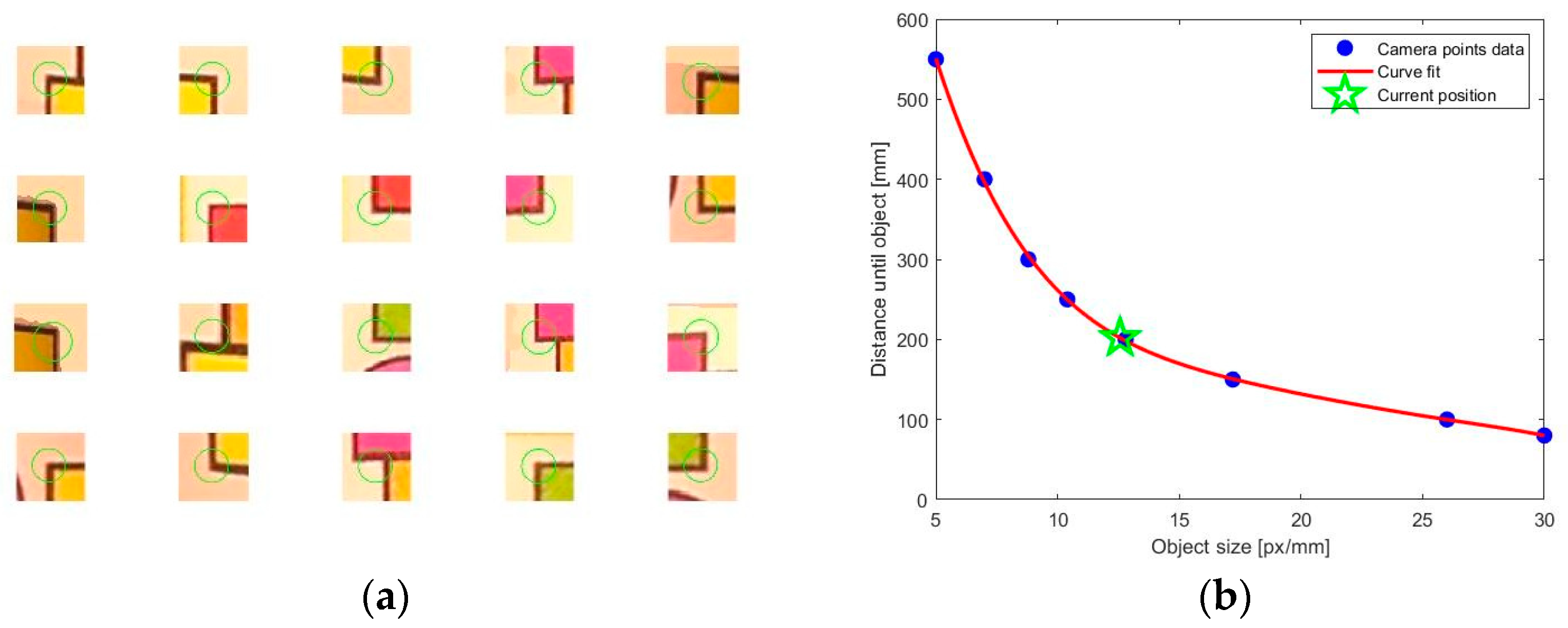
The determination of distances to objects is based on the existence of these signs on objects or in special areas (as in the second method of this study). If the size of the signs is predetermined, the correspondence curve between the size of the object in the captured image and its distance to the object can be determined experimentally. Such a curve is shown in Figure 5a for a stereoscopic 3DEvo camera with 1920 × 1080 pixel image resolution and a 33 mm distance between the cameras, while the experimental results are evidenced in Figure 6.
3.2. RPLIDAR and HQ Camera Subsystem
To perform the experiments of the identification and recognition of objects/obstacles, we used the following devices:
- Raspberry Pi HQ camera 12.30 MP
An independent high-fidelity visual peripheral mode in low light HQ camera light conditions, Raspberry Pi brand, with the interconnected structure of both hardware and software for image capture.
- 2.
- 6 mm and 3 MP fisheye lens for Raspberry Pi HQ camera
An interchangeable lens mount with CS mount, compatible with the 12.30 MP Raspberry Pi HQ camera peripheral module, with a wide angle of the real image, also called “fisheye”.
- 3.
- 16 mm and 10 MP telephoto lens for Raspberry Pi HQ camera
An interchangeable telephoto lens with a type C mount, compatible with the 12.30 MP Raspberry Pi HQ camera peripheral module, with a narrow viewing angle.
- 4.
- RPLIDAR A3 Sensor
In order to measure the distances between the designed mobile mechatronic system and the objects in the work environment, we used the omnidirectional RPLIDAR A3 sensor, a product of Shanghai Slamtec Co., which works on the principle of triangulation. It is equipped with a rotating laser beam of 16,000 rot/s, allows contour mapping of the surrounding area, positioning, and autonomous navigation and avoids obstacles. The technology incorporated into this sensor has a good sensitivity in the case of the existence of black and white bodies.
- 5.
- NVIDIA Jetson Nano P3449_B01
The Jetson Nano Model P3449_B01 is a board with optimized power and low power consumption, provided by NVIDIA Corporation, designed to run at high speeds, and simultaneously gathers much more data related to the detection and object recognition.
The research on the detection and recognition of objects using the materials presented above is carried out through the prototype of an original mechatronic system (see Figure 7a). The Raspberry Pi HQ IMX477 camera with different lenses (on the left side of the image is the 16 mm telephoto lens, and on the right side is the 6 mm “fisheye” lens). The Jetson Nano board model P3449_B01 and the RPLIDAR A3 laser scanner are installed on the mobile robotic platform.
The technique adopted for the experiments in the real environment is evidenced in Figure 7 and is explained as follows:
- The distances between the camera and the test object have values of 0.50 m, 1.00 m, and 1.50 m, taking into account the constructive restrictions of the robotic arm. The databases used are neural networks with convolutional architecture and increased accuracy, reduced in terms of capacity, respectively GoogLeNet of 54 MB and ResNet-50 of 103 MB;
- The cameras are used alternately so as not to alter the positions and technical characteristics of the visual perception subsystem;
- The software used for visualizing the environment is RViz, installed under the operating system for robots, ROS Melodic (see Figure 8b). In order to work on the NVIDIA Jetson Nano platform and to be able to collect data from the HQ camera, as well as from the RPLIDAR scanner, according to Figure 7b, this software benefits from a suite of software resources, some provided by the hardware manufacturer, and other open-source software optimized for this board. NVIDIA provides users with hardware components and software packages that are not always upgraded. In this case, the NVIDIA JetPack 4.4 SDK (Software Development Kit) was used. It was followed by the configuration of the operating system on the nano board for the robotic system to process graphic/video information, to detect objects, to calculate the distance to them, etc. In addition, software packages are required for AI, Computer Vision, image processing, interfaces, multimedia processing, graphics, etc. Figure 8a shows the basic software components;
- In order for the robotic system to use the RPLIDAR sensor (see Figure 8b), it needs software packages so that the NVIDIA Jetson Nano platform can communicate and work with it. The manufacturer of the scanning system created the Slamtec RPLIDAR Public SDK package as well as the communication with ROS, so we installed the RPLIDARNode driver (see Figure 8b) software for starting and stopping the RPLIDAR sensor motors and, finally, installed the software resources for RViz.
4. Results
The first set of experiments was carried out for the new proposed method of distance assessment by detecting objects (with low-cost cameras) based on the image characteristics of the designed signs, implemented in MATLAB.
The second set of experiments consisted of the real environment validation of the process of identifying and recognizing a test object (an orange) by the customized perception subsystem (RPLIDAR and HQ camera). Distance measurement was also performed.
Further, we performed a simulation in the virtual environment of the process of moving the robotic arm (component of the visually impaired assistive mechatronic system, VIPs-Walker) to grab the detected object.
4.1. Experiments
4.1.1. Distance Assessment Based on Sign Marker and Low-Cost Cameras
The object detection method is based on a function for feature detection in images implemented in MATLAB using the disparity evaluation method. The method is applied for both images, reference and real, and after that, a similarity evaluation is made between these features. A simple example is presented in Figure 9.
The method of determining distances to objects is based on the correspondence curve determined for the low-cost cameras used with help of a hatch-type marker, as in Figure 10a.
4.1.2. Distance Measurement and Object Recognition with HQ Camera and RPLIDAR Scanner
The following images were captured with a single camera, alternately, so as not to alter the position and technical characteristics of the visual perception subsystem and refer to a test object (glass/orange) that can be grasped by the robotic arm of the simulated mechatronic system (see Figure 11).
Basically, the information received from the RPLIDAR A3 laser scanner shows graphically what identifies the robot in space, respectively the topographic arrangement in space of all the objects encountered by the laser beam, including the contour of the test object; thus, the information (see Figure 12) helps the adjustment and control process in defining its next actions.
4.1.3. Virtual Experiments
The aim of the distance assessment and object detection study is to implement these techniques into an assistive device for VIPs. This device is designed with a robotic arm to grab objects, open doors, close windows, etc.
In this research stage, the mechatronic system’s motion strategy was implemented and tested on a virtual 3D model. A virtual reality model and a simulation were prepared using SolidWorks software. Advanced modeling and simulation give insight into how a product or process will behave without having to test it in real life, enabling the developer to observe complex behavior and, if necessary, further optimize the design and manufacturing.
A directional inverse kinematics strategy of a serial robot was applied. No monitoring took place during the arm motion. We knew the target location after the object had been detected (target point), the distance to the object, and the start position of the robotic arm. Continuous monitoring is not of interest for the present study (as it is useless for visually impaired persons), but, if required, the method could easily be applied at half or other distances away [46].
After object detection, we intended to implement for the robot arm (with 5 DOF) a control strategy to approach near to the target, which is an object to be grabbed by the visually impaired person. For the simulation test, the motion simulation capability of the professional software SolidWorks was used. At this stage of the research, the 3D model was considered, as the real prototype of the VIPs-Walker had not yet been developed. Figure 13 presents the home and deploy positions of the robot arm during the dynamic simulation.
4.2. Experimental Results
4.2.1. Results Using Low-Cost Cameras
4.2.2. Results Using RPLIDAR Subsystem
Carrying out the experiments in the natural environment of a closed space, in normal light conditions, and with a fixed resolution of 1280 × 720 pixels for the identification and recognition of a test object, namely, an orange, led to a series of digital images and measured parameters. The set of data obtained is presented in Table 2.
4.2.3. Virtual Simulation Results
The motion strategy of the robot arm included inverse kinematics evaluation. In addition, the dynamic evaluation of the robot’s capabilities could be used for a complete task design and the evaluation and optimization of the mechatronic system’s components and motion.
Figure 15 presents the results for the dynamic simulation of the robotic arm motion from the start point (where the assistive mechatronic system is) to the object (grabbing the identified object). These graphs evidence the variation of the first motor torque (the one driving the whole robot arm), velocity, and the magnitude acceleration at the hand (along the X axis).
These simulations represent the current stage of the complete design study on the VIPs-Walker assistive mechatronic system.
5. Discussion
This paper presents the research results for the distance assessment of the assistive mechatronic system using object detection and recognition techniques. The first method is a new approach based on low-cost photo cameras and special sign detection. The second is a classic technique based on a LIDAR sensor and an HQ photo camera. Its novelty is the concept and prototype of the hardware subsystem for high-precision distance measurement, as well as its fast and accurate object recognition.
The results obtained (experimentally) by each of the abovementioned techniques can be used for the elaboration of the strategies for the motion control of mechatronic systems used in healthcare and assistive living applications, specifically the robotic arm of the VIPs-Walker. An important point is that the research hypotheses and research activities were conducted based on the special needs of visually impaired persons, identified by the personal experience of one of the authors.
A discussion of the results is detailed in the next subsection.
5.1. Low-Cost Camera Subsystem
The successful distance assessment through object detection using the disparity method depends on many factors:
- -
- The quality of the images received from the camera (photo or video);
- -
- The existing colors in the image;
- -
- The most-requested color channels (R, G, or B).
The non-uniformity of the colors in the image, obvious contrasts, contrasting colors, well-defined color distribution, well-defined color groups, and large disparity are all factors that influence the success of this method of distance assessment through object detection.
In accordance with the research results, the proposals for marking the areas of interest with special signs are mentioned next.
- The use of signaling elements in the case of obvious areas to avoid: stairs, windows, cabinets, doors, corners of buildings, etc.
- The use of specially designed signs to improve the mechatronic system’s detection of distances from objects within its environment.
- The decision to use clear signaling elements will lead, in time, to the formation of a social education more correlated with the problems of people with special needs as well as methods of sensitization and education of the rest of the population to the problems of visually impaired people.
- Medium-intensity light sources, warm colors, and even scattering are recommended for lighting objects and scenes that need to be monitored using cameras.
- If necessary, additional lighting can be added to the areas in front of the device for the visually impaired (VIPs-Walker) or in situations in which a mechatronic system used for robotically controlled laparoscopic operations collaborates with a medical team.
5.2. RPLIDAR and HQ Camera Subsystem
The analysis of the datasets obtained experimentally in the real environment and centralized in Table 2 shows that, starting with a distance of 1.00 m, the 6 mm fisheye lens no longer recognizes the test object, and at a distance of 1.50 m, only the 16 mm telephoto lens correctly recognizes the test object based on images stored in GoogLeNet. At the same time, we noticed that at a distance of 0.50 m, the experimental results in the real environment with both types of objectives are very good, with the identification and recognition times being less than one second.
The 16 mm telephoto lens is preferred for 0.50 m distances due to the accuracy of the recognized classes, to the detriment of the 6 mm lens, regardless of the database used. The lowest average identification and recognition time is recorded with the 16 mm telephoto lens and the GoogLeNet database, but the accuracy of the test object classes is not very good.
The error of measuring the distance at which the test object was fixed is calculated as an absolute value (the ratio of the difference between the two values indicated by the laser scanner and the distance measured manually) and is relatively small, between 1.00% and 4.20%. This is due to the slight, involuntary change in the position of the mobile mechatronic system, the porosity of the object surface, and the vibrations induced by the rotational speed of the laser head of the RPLIDAR sensor.
We also noticed large errors, over 3.40%, in cases where the test object was not recognized.
6. Conclusions
Measuring the distance to an object in addition to the detection and recognition of objects stands as a real advantage for any assistive device used by visually impaired persons in their everyday life. Many devices use video cameras, but few use additional systems to give complementary and accurate information.
The processing of digital images captured by cameras, respectively the analysis at the pixel level and the interpretation of significant information, leads to the knowledge of the mechatronic system environment. The two new proposed methods (procedures) for distance assessment using object detection have proved to be useful for the motion strategy of the robotic arm—a component in the assistive mechatronic system for visually impaired persons.
Considering the low-cost camera subsystem, the authors’ main conclusions and targets for further research development are as follows.
- -
- Good results are obtained when the direction of the camera has a small deviation from the normal direction of the object plane (focused tissues or objects, signs, etc.). An improved method for object detection could use the stereoscopic capability of the low-cost cameras.
- -
- The maximum errors in the distance evaluation (by sign detection with low-cost cameras) exceeds the recommended 10 mm allowable error. This can be managed from the iterative inverse kinematics procedure, because the best results in the distance evaluation are obtained at approx. 250 mm value for SET-11 images when the error is 1.64% (4.1 mm). The error value also depends on the video camera focusing on the object. The focus is not always the same for the left and the right camera.
- -
- The errors in the distance evaluation method also depend on the camera resolution. The mathematical function between the real size of an object and the pixels of the object in a photo is not easy to manage and can lead to errors. However, because this idea is at the early stage of development and almost everyone can now use a simple smartphone with low-cost photo/video cameras included, this method will receive attention from many researchers in the future.
When considering the RPLIDAR—HQ camera subsystem, the authors point out that at the date of this research, no study was identified in the literature that included the combination of a Raspberry Pi HQ IMX477 camera and a RPLIDAR A3 laser scanner. The multi-sensor conceptual approach is classic, but the combination of equipment is new; the results of their collaboration were unknown prior to this study.
Basically, this paper presents the research and results obtained in the concept development and testing phase for a new visually impaired assistive device (VIPs-Walker). This device aims to be of real help to people with visual impairments, but also to people with other associated/multiple disabilities (as, unfortunately, happens many times). Because people with disabilities are of relatively poor social condition and their living resources are limited (especially in our country of Romania), this device is intended to be available at a price that many of these people could afford.
As previously mentioned in the paper, this research is based both on the real experience of one of the authors as well as on previous research (on target groups) for identifying the needs and requirements that the device would meet. The target groups included young people with mild cognitive disabilities associated with visual impairment, aged between 14 and 28, and attending vocational school, high school, or post-secondary courses in an educational institution for people with special educational needs (SEN).
This research pointed out that there are differences in the adaptation to and perception of surrounding objects, recognizing simple 3D objects used in math classes (sphere, pyramids, parallelepipeds, etc.), and, not least, spatial orientation in the halls of the institution. In fact, the virtual simulation of the robotic arm motion to grab the object resulted from the urgent need for some people in the group to take a glass from a shelf.
Based on all of the factors mentioned above, further research development is required that focuses on the following aspects:
- -
- The use of additional ultrasonics sensors in order to diminish the influence of lighting conditions on the object recognition results.
- -
- The use of stereoscopic or multiple cameras for better visualization and to obtain more useful information about scene observed. Such a video system will be implemented for a robot used in laparoscopic brachytherapy medical procedures.
- -
- The challenges in the field of visual perception subsystems are still innumerable, so in the future, we aim to diversify as much as possible the analysis of test objects to reconfirm the proposed technical solution, to modify the architecture of the subsystem by experimenting with new peripheral tools, to make subset data through the detailed parametric description for landmarks and objects that are found primarily in nature, and to study stability control based on information received from additional visual perception subsystems.
- -
- We intend to include a module that can recognize faces (a module that could be implemented through the YOLOv5x algorithm using another set of data and from other databases).
- -
- We intend to implement machine learning models for safety-critical tasks, as it is important to ensure their security and integrity. This includes protecting our models from backdoor attacks [47] and, consequently, using other types of datasets and models for backdoor defenses.
Author Contributions
Individual contribution of researchers: state of the art, C.D., I.T. and M.P.; methodology, C.D. and M.P.; software, C.D., I.T. and M.P.; validation, C.D. and M.P.; writing, C.D., M.P., I.T. and M.I.; supervision, M.I.; methods developed: C.D. for low-cost camera object detection and distance evaluation, and M.P. for mobile robotic platform; simulations, C.D. and I.T.; real experiments, M.P.; project administration, M.I. All authors have read and agreed to the published version of the manuscript.
Funding
This research received no external funding.
Institutional Review Board Statement
Not applicable.
Informed Consent Statement
Not applicable.
Data Availability Statement
During the study, parametric images were made that do not represent publicly archived datasets and were used for solution validation and mathematical calculation. All of this information can be obtained from the authors.
Acknowledgments
The background of this work was supported by the Grant of the Romanian ministry of Research and Innovation, CCCDI–UEFISCDI, PROIECT PN-III-P2-2.1-PED-2019-0085, Contract no. 447PED/2020 (Acronym: POSEIDON). The Institute of Solid Mechanics, Romanian Academy, funded some of the doctoral research for the PhD students who were authors of this paper.
Conflicts of Interest
The authors declare no conflict of interest.
References
- Fiorini, P. History of Robots and Robotic Surgery. In The SAGES Atlas of Robotic Surgery; Springer: Berlin/Heidelberg, Germany, 2018; pp. 3–14. [Google Scholar]
- Dionigi, R. Recent Advances in Liver Surgery. In Recent Advances in Liver Surgery; CRC Press: Boca Raton, FL, USA, 2009; ISBN 9781587063176. [Google Scholar]
- Dragne, C.; Chiroiu, V. Advanced Collision Detection Techniques. In Proceedings of the International Multi-Conference on Systems & Structures (SysStruc ’19), Resita, Romania, 7–9 November 2019. [Google Scholar]
- Dasiopoulou, S.; Mezaris, V.; Kompatsiaris, I.; Papastathis, V.-K.; Strintzis, M. Knowledge-assisted semantic video object detection. IEEE Trans. Circuits Syst. Video Technol. 2005, 15, 1210–1224. [Google Scholar] [CrossRef]
- Zhang, J.; Yan, Y.; Lades, M. Pace recognition: Eigenface, elastic matching, and neural nets. Proc. IEEE 1997, 85, 1423–1435. [Google Scholar] [CrossRef]
- Alsanabani, A.A.; Ahmed, M.A.; Al Smadi, A.M. Vehicle Counting Using Detecting-Tracking Combinations: A Comparative Analysis. In Proceedings of the 4th International Conference on Video and Image processing, Xi’an, China, 25–27 December 2020; pp. 48–54. [Google Scholar]
- Wu, J.; Osuntogun, A.; Choudhury, T.; Philipose, M.; Rehg, J.M. A Scalable Approach to Activity Recognition based on Object Use. In Proceedings of the 2007 IEEE 11th International Conference on Computer Vision, Rio de Janeiro, Brazil, 14–21 October 2007; Institute of Electrical and Electronics Engineers (IEEE): Piscataway, NJ, USA, 2007; pp. 1–8. [Google Scholar] [CrossRef]
- Ashiq, F.; Asif, M.; Bin Ahmad, M.; Zafar, S.; Masood, K.; Mahmood, T.; Mahmood, M.T.; Lee, I.H. CNN-Based Object Recognition and Tracking System to Assist Visually Impaired People. IEEE Access 2022, 10, 14819–14834. [Google Scholar] [CrossRef]
- Zaarane, A.; Slimani, I.; Al Okaishi, W.; Atouf, I.; Hamdoun, A. Distance measurement system for autonomous vehicles using stereo camera. Array 2020, 5, 100016. [Google Scholar] [CrossRef]
- Salavati, P.; Mohammadi, H.M. Obstacle Detection Using GoogleNet. In Proceedings of the 8th International Conference on Computer and Knowledge Engineering (ICCKE), Masad, Iran, 25–26 October 2018; Institute of Electrical and Electronics Engineers (IEEE): Piscataway, NJ, USA, 2018; pp. 326–332. [Google Scholar]
- Liu, L.; Lu, S.; Zhong, R.; Wu, B.; Yao, Y.; Zhang, Q.; Shi, W. Computing Systems for Autonomous Driving: State of the Art and Challenges. IEEE Internet Things J. 2020, 8, 6469–6486. [Google Scholar] [CrossRef]
- Li, T.; Fang, W.; Zhao, G.; Gao, F.; Wu, Z.; Li, R.; Fu, L.; Dhupia, J. An improved binocular localization method for apple based on fruit detection using deep learning. Inf. Process. Agric. 2021. [Google Scholar] [CrossRef]
- Salari, A.; Djavadifar, A.; Liu, X.R.; Najjaran, H. Object recognition datasets and challenges: A review. Neurocomputing 2022, 495, 129–152. [Google Scholar] [CrossRef]
- Montoya-Cavero, L.-E.; Torres, R.D.D.L.; Gómez-Espinosa, A.; Cabello, J.A.E. Vision systems for harvesting robots: Produce detection and localization. Comput. Electron. Agric. 2021, 192, 106562. [Google Scholar] [CrossRef]
- Mititelu, E.; Vlădăreanu, V.; Melinte, O.; Barbu, V.; Mihai, I.; Pandelea, M. Deep learning with tree classification for decisional processes on autonomous robots. In Proceedings of the SISOM & ACOUSTICS 2017. Session 2—Robotics, Bucharest, Romania, 18–19 May 2017. [Google Scholar]
- Li, J.; Li, R.; Li, J.; Wang, J.; Wu, Q.; Liu, X. Dual-view 3D object recognition and detection via Lidar point cloud and camera image. Robot. Auton. Syst. 2022, 150, 103999. [Google Scholar] [CrossRef]
- Su, H.-R.; Chen, K.-Y. Design and Implementation of a Mobile Robot with Autonomous Door Opening Ability. Int. J. Fuzzy Syst. 2018, 21, 333–342. [Google Scholar] [CrossRef]
- Chen, Y.; Zhu, K.; Huanlin, L. Blind Stereo Image Quality Assessment Based on Binocular Visual Characteristics and Depth Perception. IEEE Access 2020, 8, 85760–85771. [Google Scholar] [CrossRef]
- Sun, G.; Ding, Y.; Deng, R.; Zhao, Y.; Chen, X.; Krylov, A.S. Stereoscopic Image Quality Assessment by Considering Binocular Visual Mechanisms. IEEE Access 2018, 6, 51337–51347. [Google Scholar] [CrossRef]
- Qi, S.; Ning, X.; Yang, G.; Zhang, L.; Long, P.; Cai, W.; Li, W. Review of multi-view 3D object recognition methods based on deep learning. Displays 2021, 69, 102053. [Google Scholar] [CrossRef]
- Aldahoul, N.; Karim, H.A.; Tan, M.J.T.; Fermin, J.L. Transfer Learning and Decision Fusion for Real Time Distortion Classification in Laparoscopic Videos. IEEE Access 2021, 9, 115006–115018. [Google Scholar] [CrossRef]
- Sun, Z.; Liu, H.; Huyan, J.; Li, W.; Guo, M.; Hao, X.; Pei, L. Assessment of importance-based machine learning feature selection methods for aggregate size distribution measurement in a 3D binocular vision system. Constr. Build. Mater. 2021, 306, 124894. [Google Scholar] [CrossRef]
- Ding, Y.; Hua, L.; Li, S. Research on computer vision enhancement in intelligent robot based on machine learning and deep learning. Neural Comput. Appl. 2021, 34, 2623–2635. [Google Scholar] [CrossRef]
- Cao, L.; Wang, C.; Li, J. Robust depth-based object tracking from a moving binocular camera. Signal Process. 2015, 112, 154–161. [Google Scholar] [CrossRef]
- Danilov, Y.; Tyler, M. Brainport: An alternative input to the brain. J. Integr. Neurosci. 2006, 4, 537–550. [Google Scholar] [CrossRef]
- Google Patents. Available online: https://patents.google.com/patent/US6430450B1/en (accessed on 28 February 2022).
- OrCam Read. Available online: https://www.orcam.com/en/read/ (accessed on 3 March 2022).
- Pandelea, M.; Todirite, I.; Iliescu, M. Customized Assistive System Design for Visually Impaired People. In Proceedings of the 2020 Fourth World Conference on Smart Trends in Systems, Security and Sustainability (WorldS4), London, UK, 27–28 July 2020; Institute of Electrical and Electronics Engineers (IEEE): Piscataway, NJ, USA, 2020; pp. 467–472. [Google Scholar]
- Saputra, M.R.U.; Widyawan; Santosa, P.I. Obstacle Avoidance for Visually Impaired Using Auto-Adaptive Thresholding on Kinect’s Depth Image. In Proceedings of the 2014 IEEE 11th Intl Conf on Ubiquitous Intelligence and Computing and 2014 IEEE 11th Intl Conf on Autonomic and Trusted Computing and 2014 IEEE 14th Intl Conf on Scalable Computing and Communications and Its Associated Workshops, Bali, Indonesia, 9–12 December 2014; Institute of Electrical and Electronics Engineers (IEEE): Piscataway, NJ, USA, 2014; pp. 337–342. [Google Scholar]
- Poggi, M.; Mattoccia, S. A wearable mobility aid for the visually impaired based on embedded 3D vision and deep learning. In Proceedings of the 2016 IEEE Symposium on Computers and Communication (ISCC), Messina, Italy, 27–30 June 2016; Institute of Electrical and Electronics Engineers (IEEE): Piscataway, NJ, USA, 2016; pp. 208–213. [Google Scholar] [CrossRef]
- Xiao, J.; Ramdath, K.; Iosilevish, M.; Sigh, D.; Tsakas, A. A low-cost outdoor assistive navigation system for blind people. In Proceedings of the IEEE 8th Conference on Industrial Electronics and Applications (ICIEA), Melbourne, Australia, 19–21 June 2013; Institute of Electrical and Electronics Engineers (IEEE): Piscataway, NJ, USA, 2013; pp. 828–833. [Google Scholar]
- Faisal, M.; Reddy, G.A.; Kumar, B.A.; Ajitha, D. Object Detection using Ultrasonic Sensor. Int. J. Mod. Trends Sci. Technol. 2021, 7, 7010. [Google Scholar] [CrossRef]
- Biswas, A.; Abedin, S.; Kabir, A. Moving Object Detection Using Ultrasonic Radar with Proper Distance, Direction, and Object Shape Analysis. JISEBI—J. Inf. Syst. Eng. Bus. Intell. 2020, 6, 2443–2555. [Google Scholar] [CrossRef]
- Ecemis, I.M.; Gaudiano, P. Object recognition with ultrasonic sensors. In Proceedings of the 1999 IEEE International Sympo-sium on Computational Intelligence in Robotics and Automation. CIRA’99 (Cat. No.99EX375), Monterey, CA, USA, 8–9 November 1999; Institute of Electrical and Electronics Engineers (IEEE): Piscataway, NJ, USA, 2002. [Google Scholar]
- Basler Line Scan Cameras. Available online: https://www.baslerweb.com/en/products/cameras/line-scan-cameras/ (accessed on 20 February 2022).
- Wei, Z.; Ding, M.; Downey, D.; Fenster, A. 3D TRUS guided robot assisted prostate brachytherapy. Med. Image Comput. Comput. Assist. Interv. 2005, 8 Pt 2, 17–24. [Google Scholar] [CrossRef] [PubMed] [Green Version]
- Xue, J.; Waterman, F.; Handler, J.; Gressen, E. Localization of linked 125I seeds in postimplant TRUS images for prostate brachytherapy dosimetry. Int. J. Radiat. Oncol. 2005, 62, 912–919. [Google Scholar] [CrossRef] [PubMed]
- Xu, M.; Wang, L.V. Photoacoustic imaging in biomedicine. Rev. Sci. Instrum. 2006, 77, 041101. [Google Scholar] [CrossRef] [Green Version]
- Varghese, T.; Ophir, J. An analysis of elastographic contrast-to-noise ratio. Ultrasound Med. Biol. 1998, 24, 915–924. [Google Scholar] [CrossRef]
- Yi, Y.; Dong, L. A design of blind-guide crutch based on multi-sensors. In Proceedings of the 12th International Conference on Fuzzy Systems and Knowledge Discovery (FSKD), Zhangjiajie, China, 15–17 August 2015; Institute of Electrical and Electronics Engineers (IEEE): Piscataway, NJ, USA, 2016; pp. 2288–2292. [Google Scholar]
- Redmon, J.; Farhadi, A. Yolov3: An incremental improvement. arXiv 2018, arXiv:1804.02767. [Google Scholar]
- Introduction to YOLO Algorithm for Object Detection. Available online: https://www.section.io/engineering-education/introduction-to-yolo-algorithm-for-object-detection/ (accessed on 15 May 2022).
- Fan, Y.C.; Yelamandala, C.M.; Chen, T.W.; Huang, C.J. Real-Time Object Detection for LiDAR Based on LS-R-YOLOv4 Neural Network. J. Sens. 2021, 2021, 5576262. [Google Scholar] [CrossRef]
- Han, J.; Liao, Y.; Zhang, J.; Wang, S.; Li, S. Target fusion detection of LiDAR and camera based on the improved YOLO algorithm. Mathematics 2018, 6, 213. [Google Scholar] [CrossRef] [Green Version]
- Llados, J.; Marti, E.; Lopez-Krahe, J. A Hough-based method for hatched pattern detection in maps and diagrams. In Proceedings of the Fifth International Conference on Document Analysis and Recognition. ICDAR ’99 (Cat. No.PR00318), Bangalore, India, 20–22 September 1999; Institute of Electrical and Electronics Engineers (IEEE): Piscataway, NJ, USA, 2002. [Google Scholar]
- Dragne, C. “Directional Kinematics—First Step in Robotic Movement”, Analele Universităţii “Eftimie Murgu”, 2019, Reşiţa, Anul XXVI, Nr. 1. Available online: https://www.researchgate.net/publication/359920311_Directional_kinematics_first_step_in_robotic_movement (accessed on 3 April 2022).
- Li, Y.; Wu, B.; Jiang, Y.; Li, Z.; Xia, S.T. Backdoor learning: A survey. arXiv 2020, arXiv:2007.08745. [Google Scholar]
- Wikipedia. Available online: https://en.wikipedia.org/wiki/Object_detection (accessed on 2 February 2022).
- Manufacturing Automation. Available online: http://magazine.automationmag.com/publication/?m=32396&i=570926&p=1&ver=html5 (accessed on 12 March 2022).
- Mathworks. Available online: https://www.mathworks.com/help/vision/ref/showmatchedfeatures.html (accessed on 23 April 2022).
- Solidworks Software. Available online: https://www.solidworks.com/ (accessed on 7 March 2022).
Figure 1.
VIPs-Walker design (virtual prototype): (a) walker with its robotic arm outstretched to grab an object; (b) walker on the stairs.
Figure 1.
VIPs-Walker design (virtual prototype): (a) walker with its robotic arm outstretched to grab an object; (b) walker on the stairs.

Figure 2.
Diagram of device for visually impaired people.

Figure 3.
Initial sign types proposed for the study: (a) signs with geometrical representation; (b) signs with hatch representation.
Figure 3.
Initial sign types proposed for the study: (a) signs with geometrical representation; (b) signs with hatch representation.

Figure 4.
A successful recognition example showing all matches. (a) Features on real image; (b) features on reference image.
Figure 4.
A successful recognition example showing all matches. (a) Features on real image; (b) features on reference image.

Figure 5.
Correspondence curve between object size and distance to object for low-cost cameras. (a) Calibration curve fit; (b) low-cost cameras (authors’ mobile phones).
Figure 5.
Correspondence curve between object size and distance to object for low-cost cameras. (a) Calibration curve fit; (b) low-cost cameras (authors’ mobile phones).

Figure 6.
Feature detection and object distance localization on calibration curve. (a) 20 features detected; (b) localization on calibration curve for an object at a 200 mm distance.
Figure 6.
Feature detection and object distance localization on calibration curve. (a) 20 features detected; (b) localization on calibration curve for an object at a 200 mm distance.

Figure 7.
Mobile robotic platform. (a) Overview; (b) hardware platform block diagram.

Figure 8.
Software architecture of the proposed mechatronic system. (a) Software resource packages (NVIDIA JetPack SDK) required for the operation of the Jetson Nano platform; (b) software architecture of the proposed mobile mechatronic system with Jetson Nano Developer Kit and ROS Melodic.
Figure 8.
Software architecture of the proposed mechatronic system. (a) Software resource packages (NVIDIA JetPack SDK) required for the operation of the Jetson Nano platform; (b) software architecture of the proposed mobile mechatronic system with Jetson Nano Developer Kit and ROS Melodic.

Figure 9.
Test for image recognition based on sign marker. (a) Real image; (b) reference image.

Figure 10.
Experimental determination of correspondence curve. (a) Graph paper used; (b) feature recognition based on the method.
Figure 10.
Experimental determination of correspondence curve. (a) Graph paper used; (b) feature recognition based on the method.

Figure 11.
Distance measurement and object recognition by HQ Camera and RPLIDAR scanner. (a) 0.50 m distance screenshot, 6 mm fisheye lens, GoogLeNet database; (b) 1.50 m distance screenshot, 16 mm telephoto lens, GoogLeNet database.
Figure 11.
Distance measurement and object recognition by HQ Camera and RPLIDAR scanner. (a) 0.50 m distance screenshot, 6 mm fisheye lens, GoogLeNet database; (b) 1.50 m distance screenshot, 16 mm telephoto lens, GoogLeNet database.

Figure 12.
Curved contour test object located on the west direction of the plane, at a distance of 1.00 m.
Figure 12.
Curved contour test object located on the west direction of the plane, at a distance of 1.00 m.

Figure 13.
Dynamic simulation of robot arm motion. (a) Home position of robot arm; (b) position near target.
Figure 13.
Dynamic simulation of robot arm motion. (a) Home position of robot arm; (b) position near target.

Figure 14.
Reference images used for Table 2. (a) SET-8; (b) SET-11; (c) SET-12.
Figure 14.
Reference images used for Table 2. (a) SET-8; (b) SET-11; (c) SET-12.

Figure 15.
Robot arm simulation test for strategy and dynamic evaluation.


Table 1.
Experimental distance evaluation based on low-cost cameras’ vision.
| Images Set | Real Distance | Left Camera | Right Camera | ||
|---|---|---|---|---|---|
| (mm) | Calculated | Error (%) | Calculated | Error (%) | |
| SET-8 | 150 | 165.88 | 10.59 | 200.81 | 33.87 |
| 200 | 205.44 | 2.72 | 210.13 | 5.07 | |
| 250 | 263.25 | 5.3 | 290.21 | 16.08 | |
| 300 | 318.65 | 6.22 | 333.25 | 11.08 | |
| SET-11 | 150 | 164.47 | 9.64 | 163.82 | 9.21 |
| 200 | 205.43 | 2.71 | 212.83 | 6.41 | |
| 250 | 257.07 | 2.82 | 254.10 | 1.64 | |
| 300 | 314.70 | 4.90 | 314.27 | 4.75 | |
| SET-12 | 150 | 179.36 | 19.57 | 179.17 | 19.44 |
| 200 | 224.02 | 12.01 | 265.52 | 32.76 | |
| 250 | 288.06 | 15.22 | 291.65 | 16.66 | |
| 300 | 363.16 | 21.05 | 324.33 | 8.11 | |
Table 2.
Test object recognition experimental research results. (UO = unrecognized object).
| GoogLeNet Database | ResNet-50 Database | Fisheye Lens | Telephoto Lens | Distance (mm) | Measured Average Distance (mm) | Distance Error (%) | Average Frame (fps) | Class Accuracy (%) |
|---|---|---|---|---|---|---|---|---|
| x | x | 500 | 509 | 1.80 | 13.34 | 60.00 | ||
| x | x | 500 | 493 | 1.40 | 17.48 | 50.00 | ||
| x | x | 1000 | 1011 | 1.10 | 14.16 | 8.33 | ||
| x | x | 1000 | 985 | 1.50 | 19.20 | 8.33 | ||
| x | x | 1500 | 1562 | 4.13 | UO | 0.00 | ||
| x | x | 1500 | 1526 | 1.73 | 18.98 | 11.67 | ||
| x | x | 1500 | 1440 | 4.00 | UO | 0.00 | ||
| x | x | 1500 | 1557 | 3.80 | UO | 0.00 | ||
| x | x | 1000 | 966 | 3.40 | UO | 0.00 | ||
| x | x | 1000 | 1042 | 4.20 | UO | 0.00 | ||
| x | x | 500 | 491 | 1.80 | 13.51 | 36.46 | ||
| x | x | 500 | 495 | 1.00 | 17.85 | 8.33 |
Publisher’s Note: MDPI stays neutral with regard to jurisdictional claims in published maps and institutional affiliations. |
© 2022 by the authors. Licensee MDPI, Basel, Switzerland. This article is an open access article distributed under the terms and conditions of the Creative Commons Attribution (CC BY) license (https://creativecommons.org/licenses/by/4.0/).
Share and Cite
MDPI and ACS Style
Dragne, C.; Todiriţe, I.; Iliescu, M.; Pandelea, M. Distance Assessment by Object Detection—For Visually Impaired Assistive Mechatronic System. Appl. Sci. 2022, 12, 6342. https://0-doi-org.brum.beds.ac.uk/10.3390/app12136342
AMA Style
Dragne C, Todiriţe I, Iliescu M, Pandelea M. Distance Assessment by Object Detection—For Visually Impaired Assistive Mechatronic System. Applied Sciences. 2022; 12(13):6342. https://0-doi-org.brum.beds.ac.uk/10.3390/app12136342
Chicago/Turabian StyleDragne, Ciprian, Isabela Todiriţe, Mihaiela Iliescu, and Marius Pandelea. 2022. "Distance Assessment by Object Detection—For Visually Impaired Assistive Mechatronic System" Applied Sciences 12, no. 13: 6342. https://0-doi-org.brum.beds.ac.uk/10.3390/app12136342
Note that from the first issue of 2016, this journal uses article numbers instead of page numbers. See further details here.