Article

Integrated Fuzzy-Logic and Triple-Loop PI-Based Management Strategy for a Lead-Acid/Lithium-Ion Hybrid Battery Energy Storage System

by
Mpho J. Lencwe
1,*,
Andre T. Puati Zau
1,
S. P. Daniel Chowdhury
2 and
Thomas O. Olwal
1
1
Department of Electrical Engineering, Faculty of Engineering and Built Environment, Tshwane University of Technology, Pretoria 0001, South Africa
2
S5 Enterprises, Cape Town 7700, South Africa
*
Author to whom correspondence should be addressed.
Submission received: 7 May 2022 / Revised: 28 June 2022 / Accepted: 1 July 2022 / Published: 8 July 2022
(This article belongs to the Special Issue Contributions to Modeling and Control of Power Electronic Converters)

Abstract

:
The huge success of electric vehicles across the world is challenged by a lack of infrastructure and a major increase in battery material prices. This challenge positions internal combustion engine vehicles (ICEVs) to remain a vehicle of choice. The majority of these vehicles use a lead-acid battery (LAB) for starting, lighting, and ignition (SLI) functions. However, these LABs are faced with challenges of short lifespan and low storage capacity because of improved electronic systems in modern ICEVs. In this manuscript, we propose an extension application of a hybrid LAB and lithium-ion energy storage system (ESS) for a vehicle using a single source of 70 Ah and 90 Ah capacity. Whereas previously, a hybrid energy storage system (HESS) for use in a vehicle using a source of 50 Ah battery capacity was proposed. Hence, the unique contribution of the study is using an integrated fuzzy-logic and triple-loop-proportional-integral-based battery management strategy (BMS) to improve LAB performance in a wide range of vehicles with different battery capacities sizes. The results show that the proposed BMS can help increase LAB lifespan and improve the storage capacity of the system, thus ensuring reliability. Additionally, compared to a single use of LAB, the combined energy storage system shows superior performance.

1. Introduction

Recently, more than ninety-nine percent of the world’s transport vehicles (TVs) are internal combustion engine vehicles (ICEVs), and ninety-five percent of their energy comes from liquid fuels as well as the petroleum industry [1]. The growth of electric vehicles (EVs) in most developed countries has taken centre stage and has seen rapid uptake growth from consumers. However, this trend is not similar in other parts of the world, especially in developing and underdeveloped economies. As indicated in [2], China, Europe, and the United States of America account for 2/3 of the overall car market, but currently, 90% are EVs. In other parts of the world, EVs account for less than 2% of overall car sales. Whereas, in developing economies such as Brazil, India, and Indonesia, the EV share is less than 1% and without any increase. Although sales of electric scooters and buses are growing in these nations, the price tag attached to EVs and the lack of charging infrastructure is the main reason for the lack of adoption [3]. Despite the drive for sustainability to decarbonise the transport sector by moving from conventional fossil fuel internal combustion engine vehicles to EVs, this move may take a long time for developing and underdeveloped economies. The big success for EVs in the whole world is challenged by limited supplies of components and increases in prices for energy storage materials. Therefore, ICEVs will remain the vehicle of choice in the coming years for many consumers in developing and underdeveloped economies [4]. These ICEVs include micro-hybrid vehicles (MHEVs), hybrid EVs (HEVs), and plug-in hybrid EVs (PHEVs). The ICEVs position lead-acid batteries (LABs) as major energy storage to start, ignite, and light (SLI) as well as for backup power supply because they have dominated the market share due to their ability to meet the needed cold-cranking of the internal combustion engine (ICE), robustness, and high-temperature endurance [5,6]. LABs have seen industrial machinery applications in forklifts, locomotives, uninterrupted power supplies, electric substations, etc. They have proven reliability, lower cost, lower self-discharge rate, extra-ordinary safety performance, and compact enclosure [7]. However, the increase in electronic functions such as sensors, and control units, amongst others, to improve vehicle comfort, safety, start/stop and go, and reliability have resulted in increased battery load demand. Furthermore, additional systems, including driver assistance, autonomous driving, recuperation of braking energy, vehicle stabilisation, and acceleration, require high peak electric power [8,9]. This increase in battery load demand increases battery degradation, thus affecting the battery performance by shortening its lifespan and reducing the storage capacity [10,11]. The short lifespan, relatively lower depth-of-discharge (DoD), and slow charging rate create an unfavourable environment in recent vehicle applications [12]. Additionally, LABs’ performance in terms of lifespan and storage capacity is affected by the way they are charged/discharged, which results in softening and shading of positive active material [13]; from a chemical point of view, negative electrode failure during discharge, positive active material corrosion, and premature capacity loss during deep discharge occur [14]. While more research looks at different ways to develop lightweight batteries that have a longer lifespan and enhanced safety, such as in [15], where polyaniline-modified lignosulfonate is added to a negative material of LAB, to improve its lifespan. Subsequently, in Ref. [16], the authors use stereotaxically constructed graphene to prevent sulfation and enhance the high rate of discharge capability, battery capacity, and lifespan. Further studies on chemistry development are included in [17]. Yet, these methods are expensive, time-consuming, and require complex equipment, correspondingly. Thus, if the battery chemistry is untampered and a new design is developed, it can achieve more in terms of satisfying vehicle load requirements. Again, the new design has to depend on the cell-to-pack design and battery size for better performance [18].
On the other hand, lithium-ion batteries (LIBs) have a wide attraction in modern automobile technologies such as EVs and PHEVs because of their superior performance, decreasing cost, and recently, as a “drop-in” to replace LABs in ICEVs. Nevertheless, LIB’s market share remains low in these applications [19]. The current price of these batteries is still high, and it requires a significant reduction for wide adoption [20]. Moreover, these batteries may pose thermal runway and safety concerns if used as an SLI because of the abused operating nature of this application [5]. In addition, LIBs face extreme difficulty in using their energy, especially at a pack level, because active or passive cell balancing becomes crucial. Despite these challenges, the LIBs have a high energy density, high utilisation efficiency, long lifespan, and are friendly to the environment. The developed lithium-ion phosphate batteries (LFPs) have many advantages compared to the conventional LIBs because their material is abundant, safe, weigh less, has high cycling loads, reduced memory effect, has higher power density, and is less costly. They are commercially available and used in many applications such as storage for renewable energy, electric buses, and EVs (e.g. Tesla, Volkswagen, Renault, and Ford) because of their good thermal/cycling stability, safety, and resilience to the environment [7,12,18,21,22]. Even though they have the best combination of excellent properties for certain vehicle applications, the use of Li-ion batteries in developing and underdeveloped economies for SLI functions remains a challenge because of the lack of established recycling processes and factories. The adoption of various combinations of battery storage systems may increase the chance to clean and less-carbon TVs [23], and without tampering with battery chemistry, the new battery designs may be developed, thus depending on the battery size [18]. Hence, providing cost tradeoff [24] of hybrid different battery technologies requires an excellent power management system to adequately share the power and improve the performance of these batteries in terms of lifespan, power delivery, and storage capacity. Moreover, because generally, during vehicle operation, the unstable power supply may occur and cause unusual operation of these devices, the power management and control could stabilise the power distribution of the energy storage systems, thus managing load demand effectively [25], enhancing battery safety, reliability, and security, respectively. Still, BMSs face different challenges, such as diversity of applications and withstanding unprecedented hazardous events [26].
Therefore, the main purpose of this research paper is to improve LABs’ performance in terms of lifespan and storage capacity. Because this study accomplishes its objective without tampering with LAB chemical composition, hence; there is a need for a complex system comprising power electronics for managing power in/out of the combined ESSs rather than a simple system of replacing LAB with Li-ion battery. The proposed solution provides a sound practical value because LABs are easily accessible and less costly in developing and underdeveloped economies. Additionally, this study gives significant theoretical value.
Furthermore, a Li-ion battery as a replacement for LAB is not a good solution because currently, it has a higher cost, is not competitive with LABs, has low recycling efficiency, and in terms of safety, high power demand in ICEVs may vary, and it is unknown at this stage as to how they will perform under such circumstances. In the proposed solution, there is no feasible reliability because the system operates effectively over its lifespan during the investigation. Moreover, the system stability proved its robustness because its SoC did not worsen during testing.
Thus, this paper contributes the following;
  • We develop and propose a HESS using a fully active topology approach that will supply the vehicle’s required cold cranking current for starting because it provides a higher degree of control freedom and efficiency. This development and proposal add an influence to studies in [5,27] and [28], wherein [5], the study discusses the challenges that may face LIBs when used for SLI functions. Additionally, in [27], the authors propose potential methods for using hybrid ESSs for SLI functions.
  • We develop an integrated fuzzy-logic and triple-loop PI-based controller to effectively distribute the power between the ESSs. The integrated solution ensures that the batteries operate within their desired limits. A contribution that enhances the performance in [29], in which the study assessed the system in terms of improving vehicle range only.
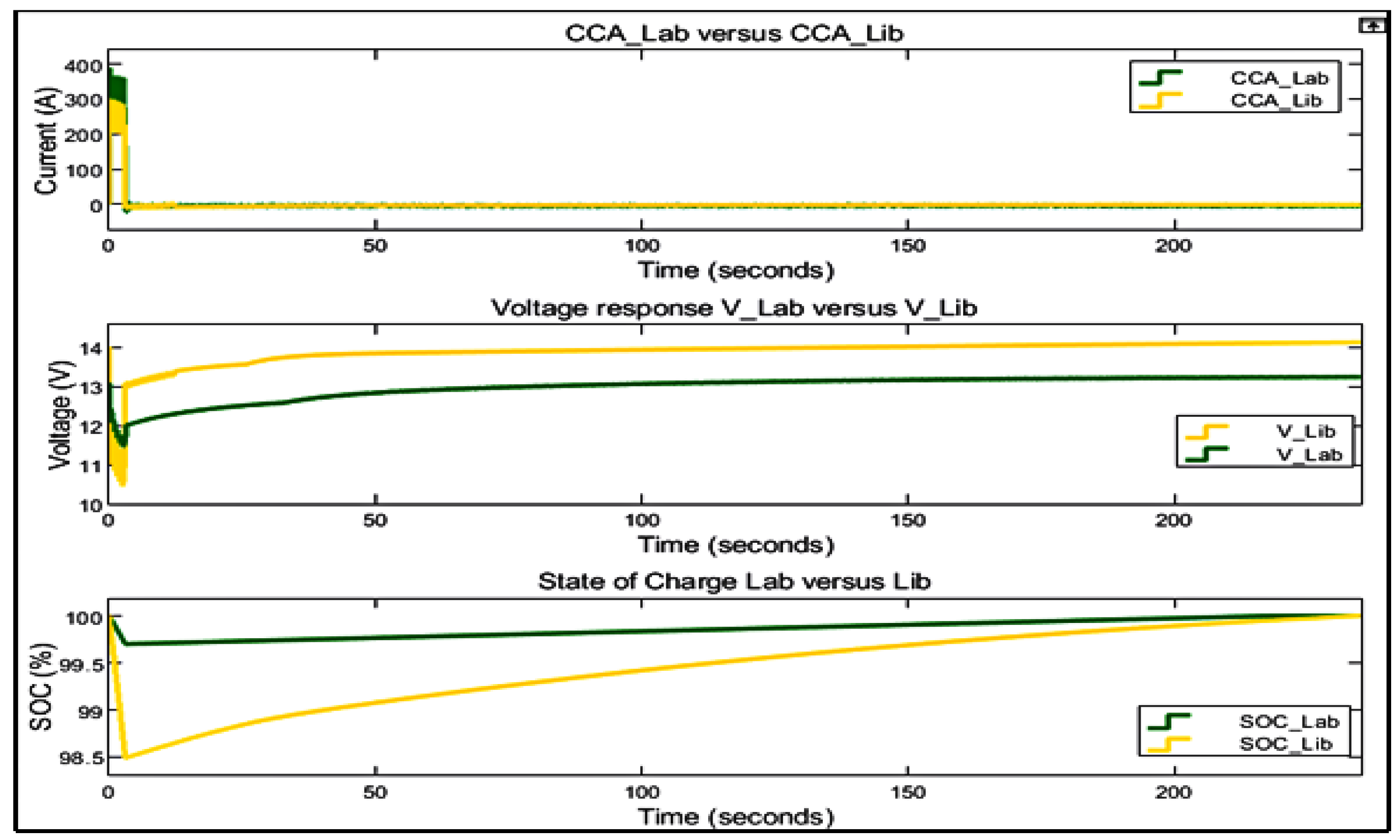
  • We compare the performance of a single source battery for the HESS in terms of delivering the required cold cranking current.
  • We enhance the performance of LAB in terms of lifespan and storage capacity improvement.
  • We develop the HESS that has great longevity, less weight, and is reliable for use in the automotive sector.
  • We propose a battery life determination using a fatigue-cycle counting approach because it is well established and easy to implement.
Thus, the paper breakdown is as follows: Unit 2 discusses the recent state-of-the-art literature within the subject area, and Section 3 describes the methods and materials adopted to achieve the results of the study. Section 4 presents the study results and elaborates the results significantly. Lastly, Section 5 provides the study concluding remarks and future area of study recommendations.

2. State-of-the-Art Literature Analysis

This section discusses the recent literature available within the HESS comprising LIB and LAB. Additionally, different battery management strategies and their control are further discussed. Taking into account the existing ICEVs around the world now, authors in [30,31] suggest that further improvements in ICE can help in decreasing the greenhouse-gas emissions that are currently caused by TVs. This reduction can be achieved through technological advancements, which include enhancing engine efficiency, incorporating hybrid energy storage sources, and using renewable fuels that contain a lower carbon footprint (i.e., Green hydrogen). The effect of lead-acid battery’s short lifespan poses challenges in recent ICEVs. Although LIB has shown great progress and as a solution for SLI application to potentially replace LABs, these batteries have several challenges, including; higher cost, which is not competitive to LABs, their recycling efficiency is low, and in terms of safety, the high power demands in ICEVs may vary from the high current over short periods to deep discharge cycles, and it is unknown at this stage as to how these batteries will perform under these circumstances [5,27]. Many studies have proposed different solutions for improving LAB’s lifespan for use in TVs, such as in [32], where the authors combine LAB with a supercapacitor using a battery semi-active cascaded topology approach. This topology connects the battery to the bidirectional DC–DC converter input, and the supercapacitor is connected to the converter’s output. The converter is controlled by a fractional-order proportional-integral-derivative (FOPID) controller to properly charge and discharge the HESS. The HESS operation is optimised by using an atom search algorithm to enhance the LAB lifespan. The study also compared the FOPID with fuzzy logic controller for enhancing battery lifespan. FOPID shows superior performance as compared to fuzzy logic control during HEV operation. On the other hand, [29] proposes a double switching-based control for a combination of LAB and LIB energy storage systems for EVs to explore the batteries’ pros and cons. This control selects the battery to be used during different vehicle operation modes under specified conditions and limits. The outcomes of the experimental study show that the HESS saves up to 68.62% of LABs and 29.48% of LIBs energy as compared to a single use of LAB, thus enhancing vehicle travelling range. Moreover, the LIB is used as an auxiliary source to support the LAB. In addition, the proposed system has a lower mass and lower price when compared to a single battery system. However, the study did not provide a cost analysis of the system compared to a single battery system. In [33], a combination of LIB, LAB, and a supercapacitor is proposed to overcome the short vehicle range and longer charging time challenges in EVs. The authors use a bidirectional cuk converter and an energy management system (EMS) to improve the HESS efficiency by providing efficient power-sharing amongst the ESSs. In this study, LIB is considered the main energy source, LAB is the auxiliary source, and SC provides LAB support to handle rapid power dynamics during vehicle acceleration and braking. The EMS uses two-stage pulse width modulation (PWM) signals and a simple PI control providing charging to the batteries using a constant-current-constant voltage (CC-CV) method. Furthermore, the authors in [34,35] propose a combination of LAB and a supercapacitor using a fully active topology approach for TVs. In this study, the authors emphasise that allowing the supercapacitor to absorb high transient power requirements from the TV can improve LAB performance significantly in terms of lifespan.
Therefore, despite the rich, relevant literature on the hybridisation of LIB and LAB, there is little attention to the use of HESS for providing starting functions or as an SLI for ICEVs. The current literature focuses more on solving a limited range of issues in EVs. Additionally, although extensive research exists for enhancing LABs lifespan, related studies combine LAB with a supercapacitor, and there is little attention to the LAB and LIB combination. Additionally, there exists no literature that provides the EMS-based on integrated fuzzy logic and triple-loop PI-based control for effective power-sharing of hybridised LIB and LAB. LIB and LAB provide the shared, required cold cranking current needed to start the vehicle in three-second. Two case studies are considered for the ICEVs that use a single battery capacity of 70 Ah and 90 Ah. These batteries can be replaced with a single HESS that provides the required cold cranking current (CCC) at a reduced weight and cost.

3. Materials and Methods

In this section, the ICEVs engine cold cranking current for 70 Ah and 90 Ah is evaluated. In addition, battery modelling, bidirectional DC–DC converter development, integrated fuzzy logic and triple-loop PI-based control, and HESS are considered, respectively. Moreover, the required CCC percentage sharing between LAB and LIB during vehicle starting is presented while ensuring that the ESS’s state-of-charge (SoC) is maintained within desirable limits during charging and discharging modes to enhance HESS lifespan.

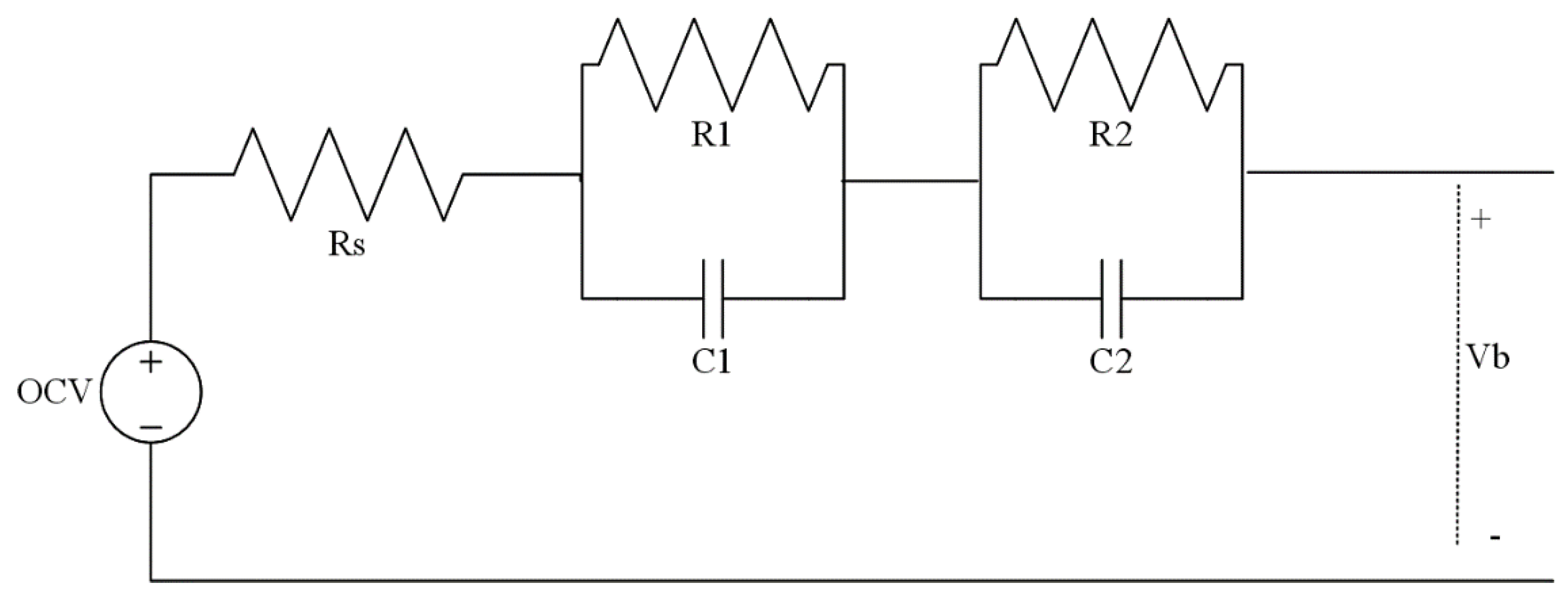
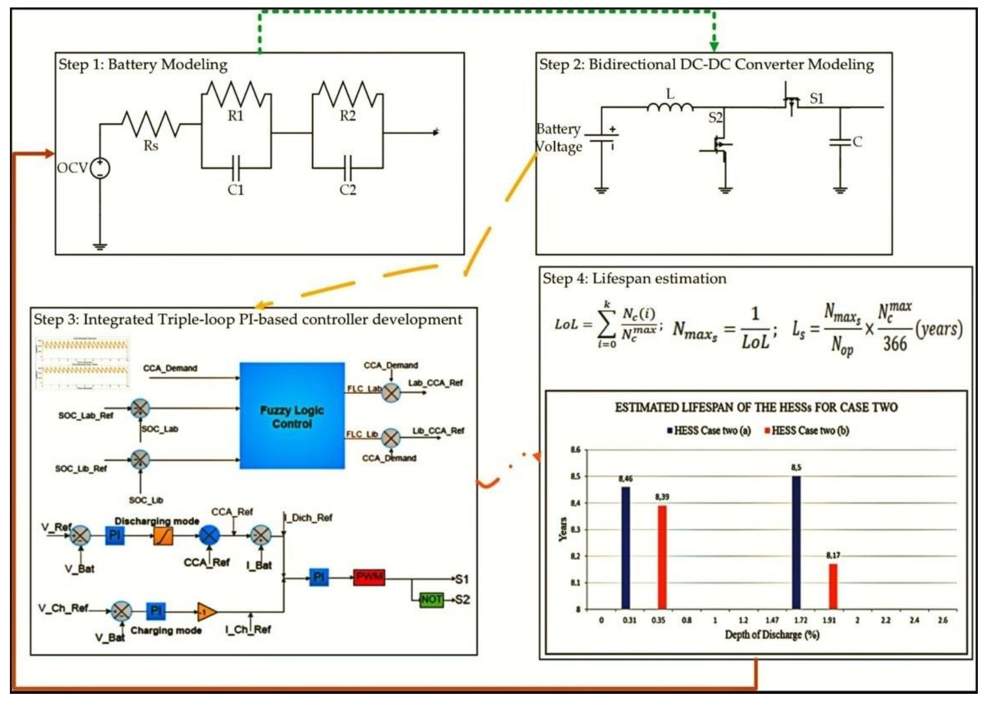
3.1. Battery Equivalent Circuit Model

The LAB and LIB battery adopted for this study was based on parameters, which include power density, life cycle, charging and discharging rate, temperature, cost, weight, and safety. Figure 1 shows the battery equivalent circuit model with associated parameters. The battery equivalent circuit model was preferred for this study because it provides accurate results for the battery behaviour between computational requirements and determining the voltage precisely [36]. This model consisted of four important parameters named open-circuit-voltage (OCV), internal series resistance, and the second-order resistor-capacitor parallel branch.
Figure 1 represents the battery equivalent circuit model, where OCV stands for battery open-circuit potential, Rs stands for the inner series resistance, and R1, R2, C1, and C2 are the parallel branch network to determine the transient response of the terminal voltage. R1 and C1 represent the small-time constant to provide battery cell feedback and are modelled as a double-layer capacitance and transfer charge. Whereas R2 and C2 provide lengthy time-constant to provide battery feedback and represent the cell diffusion procedure. Lead-acid and Lithium-ion battery models for the proposed research study were obtained from the MATLAB/Simulink library. This battery contained its parameters, which were altered according to the specification of the commercial battery. The battery parameters are estimated based on Figure 1 and by [38]. Moreover, battery depth-of-discharge directly impacts the SoC, which is important to help reduce battery stress. The battery SoC was determined as in Equation (1) [35]:
S o C ( t ) = Q s ( t ) Q b ( t ) ;
where S o C ( t ) represent the battery’s dynamic state of charge, Q s ( t ) is the battery stored charge or capacity and Q b ( t ) stand for the actual battery capacity.
However, the battery stored capacity is dependent on the battery charging current, as shown in Equation (2):
Q s ( t ) = i b ( t ) d t ;
where i b stands for the battery charging current. The battery current is assumed positive when the battery discharges and negative when the battery is charging.
Therefore, the battery dynamic SoC can be represented as in Equation (3):
S o C ( t ) = S o C i n i t i b ( t ) Q b a t t d t ;
where S o C i n i t is the battery’s initial state of charge.
The voltage across the RC branch was determined as in Equations (4) and (5) [37]:
V = 1 s [ ( 1 c ) ( V R C ) ] ;
V b = O C V V 1 V 2 V s ;
where V s stand for a voltage drop in the internal series resistance. Thus, the total battery circulating current is shown as in Equation (6) [37]:
i c = ( V R C ) + s C V ;
where i c is the battery circulating current, V R C and s C V are the currents flowing through the parallel RC branches.

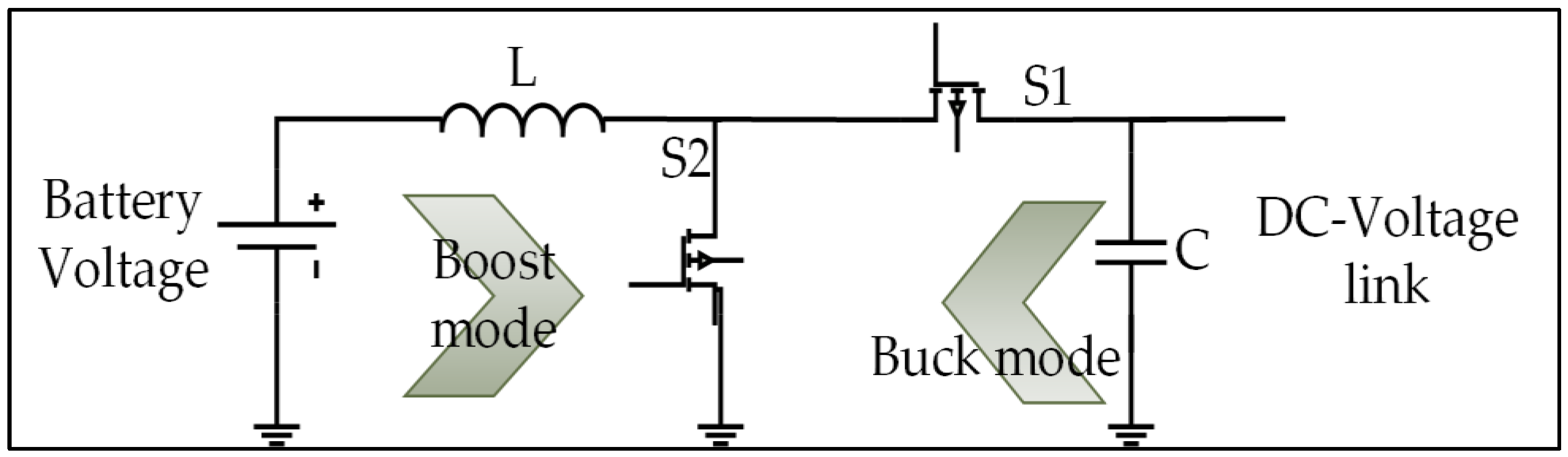
3.2. Bidirectional DC-DC Converter

In this section, a simple bidirectional DC–DC converter development for the energy storage systems was developed to provide the vehicle with the required voltage and current at the DC bus link. The DC–DC buck-boost converter equivalent circuit model was adopted from [39,40]. The voltage assumed for LAB is 12.223 V and for LIB is 12.8 V. The alternator voltage in the ICEVs normally ranges from 12 V to 14.8 V, as described in [41]. Therefore, Figure 2 shows a simple bidirectional DC-DC converter developed.
In Figure 2, during the DC–DC converter boost mode operation, the battery provides current to the DC-bus link and the battery voltage is stepped up to match the required DC-bus voltage of between 12 V and 14 V. The current is normally continuous and has a ripple that depends on the value of the inductance and switching frequency. When the S1 is ON (close), the S2 is OFF (close) because of the complementary mechanism between the signal which controls the two switches. The input voltage and inductor voltage are equal (i.e., V b a t t = V L ) and can be expressed as in Equation (7) [37]:
V L m i n = V B a t t = L m i n ( d i L m d t ) ;
where V L m i n is the minimum inductor voltage, V B a t t stands for the battery voltage, and L m i n is the minimum size of the inductor. Therefore, the minimum inductor current was determined as expressed in Equation (8) [37]:
Δ i L m i n ( o n ) = V L L m i n · D T ;
where Δ i L m i n ( o n ) is the change in minimum inductor current, V L stands for the inductor voltage, D T is the duty cycle and the total sampling or operation period.
Thus, taking into consideration when S1 is OFF and switch S2 is ON, V L m for this state was determined as in Equations (9) and (10) [37]:
V L m i n = V b a t t V o = L m i n d i L m d t ;
Δ i L m i n ( o f f ) = V L V H L · ( 1 D ) T ;
where V o represent the output converter voltage, V L and V H is the low and high voltage of the inductor voltage. Hence, the converter parameters were determined by using Equations (11) and (12) as follows:
D = 1 V s V o ;
where D is the duty cycle and ranges between 0–0.99, V s representing the DC input converter voltage and V o is the converter output voltage. Thus, the inductance and capacitance of the converter are as in Equations (12) and (13) [37]:
L m i n = D ( 1 D ) 2 × V o 2 f s I o ;
C m i n I o D f s × Δ V o ;
where I o is the CCC and f s stands for the switching frequency and is considered as 25 kHz. While the C m i n is the minimum capacitance, Δ V o is considered as 2% V o .
Whereas during the buck mode operation, the battery receives charge from the alternator through the DC-bus link because the alternator produces more power than required and acts as a generator. The battery is charged and discharged as they prefer through the control. The converter steps down the alternator voltage from 14.5 V to the required battery charge voltage, which is 13.1 V for LAB and 14.2 V for LIB. Therefore, When S2 is ON, S1 is OFF during this mode of operation because of the complementary mechanism between the signals which control the two switches. Hence, the minimum inductor voltage was determined as in Equation (14) [37];
V L m = V D C B u s V B a t t = L m · d i L m d t ;
where V D C B u s is the voltage at the DC-bus link.
Hence, when S2 is OFF and the S1 is ON, V L m could be expressed as in Equation (15) below [37];
V L m = V B a t t = L m · d i L m d t ;
Therefore, the converter parameters during the buck mode were determined as in Equations (16) and (17) [37];
D = V o V i n ;
L m i n b u c k ( 1 D ) 2 V o I o 2 f s ;
where Δ I L is considered as 20% of I L .
Battery charging, discharging voltage, and current were controlled based on the proposed controller for the battery management strategy. Table 1 shows the converter parameters for both battery capacities under study.

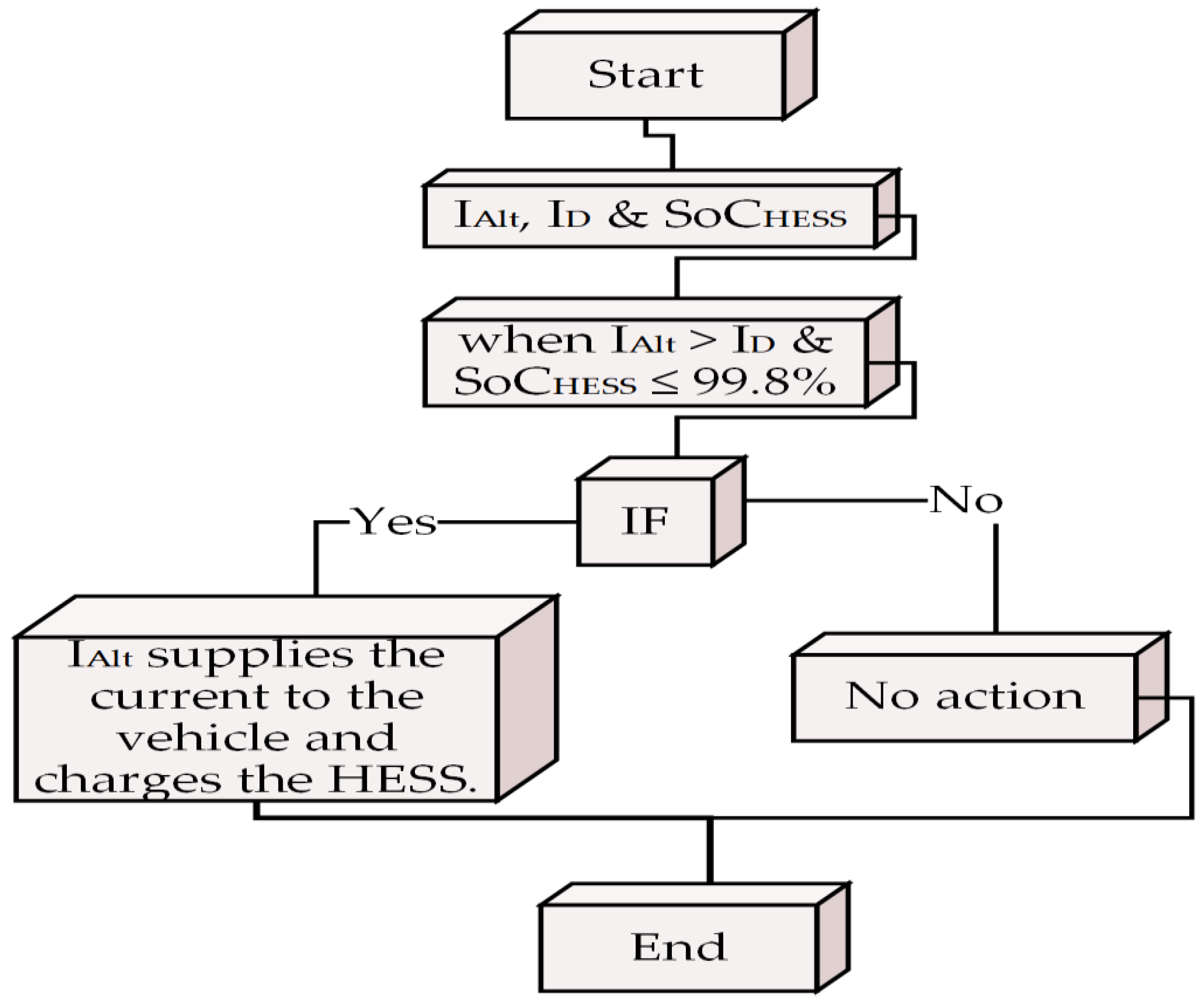
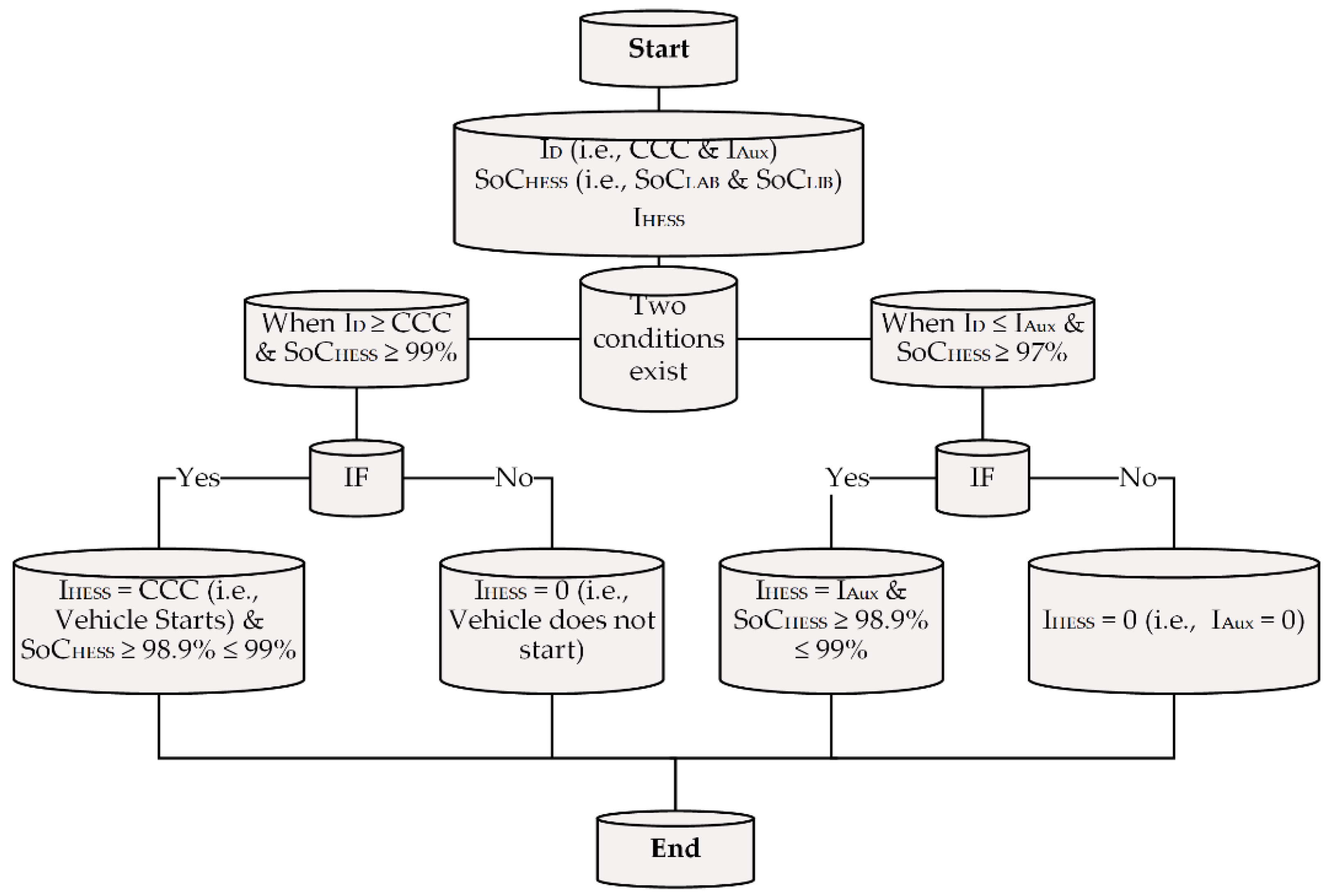
3.3. Battery Management System

This section describes and discusses the battery management strategy control development for effective power-sharing between the hybridised ESSs. The BMS proposed in this study manages the operation of HESS. The BMS is designed based on the required current and the characteristics of each battery technology. The proposed HESS with BMS operates in two modes, as shown in Figure 3 and Figure 4. The charging mode; is when the HESS is being charged by the alternator, and the discharging mode is when the HESS is supplying CCC to start the vehicle.
Figure 3 and Figure 4 show the operation of the HESS during the charging and discharging modes. During the charging mode, the HESS needs to meet the following conditions:
  • when I A l t > I D e m a n d   and   S o C H E S S 99 % , the alternator supplies the current to the vehicle while charging the battery simultaneously. While during discharging, the following conditions have to be met;
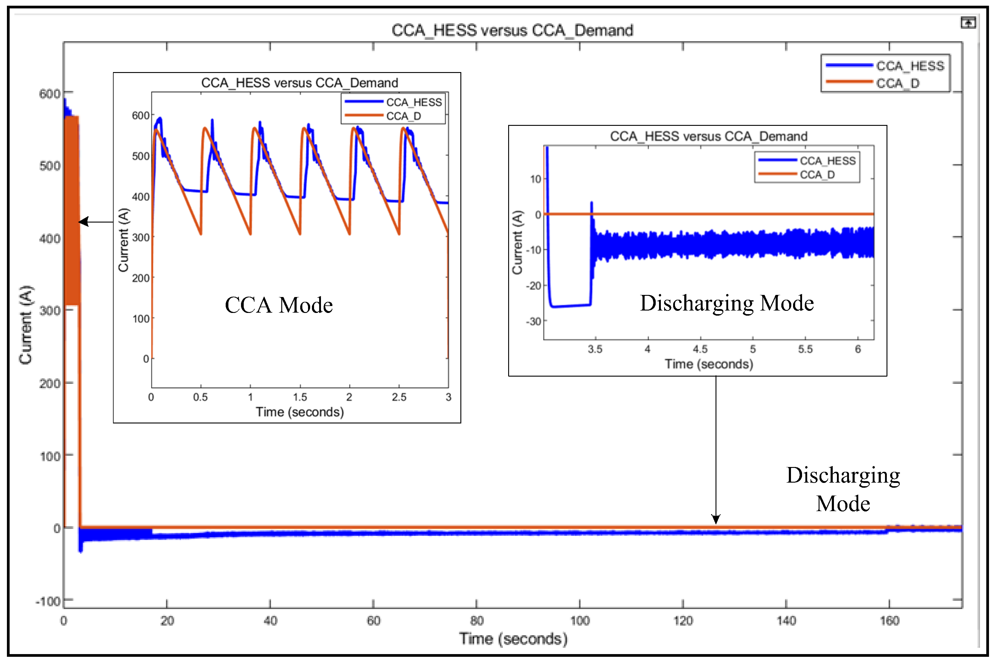
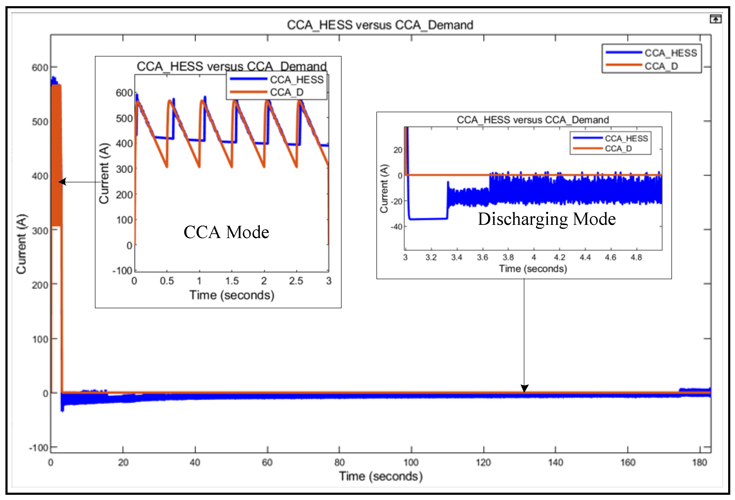
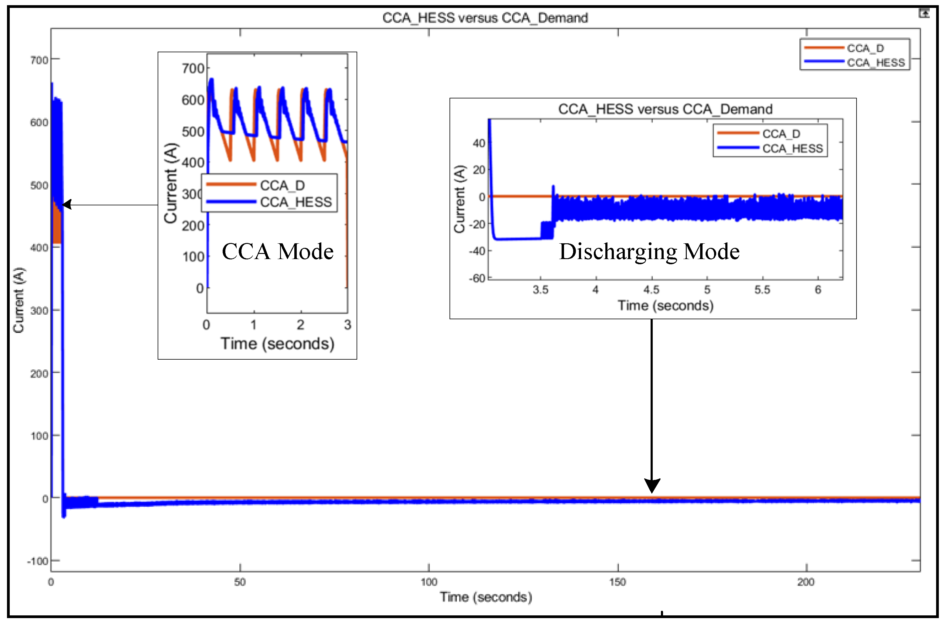
  • when I D e m a n d C C C and the S o C H E S S 99 % (i.e., S o C L A B = 100 %   S o C L I B = 100 % ), which means that the HESS supplies the required CCC to start the vehicle while maintaining the HESS SoC above 98.9%.
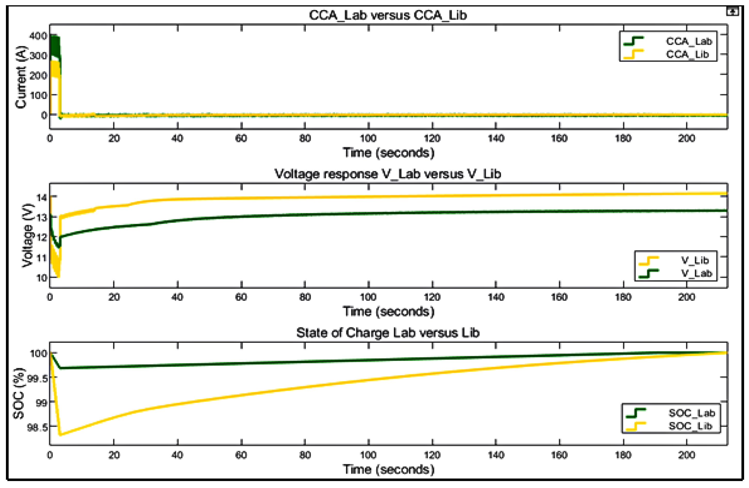
  • when I D e m a n d I A u x and S o C H E S S 97 % , means that the HESS supplies the auxiliary loads of the vehicle while sustaining the HESS state-of-charge above 97%.

Integrated Fuzzy-Logic and Triple-Loop PI-Based Control

In this subsection, the integrated fuzzy logic and triple-loop PI BMS-based control for the HESS is discussed. The bidirectional DC–DC buck-boost converters were controlled by the pulse width modulation (PWM). The voltage and current of the converters were controlled by the PI controllers. The control technique controls the input voltage and generates the required output voltage and current based on the reference voltage and current. The controller was used to improve the efficiency of the bidirectional DC–DC buck-boost converter by controlling the current and the voltage during charging and discharging modes. The single-loop PI control could not achieve the desired stability, voltage, and current output of the bidirectional DC–DC buck-boost converters. Therefore, a triple-loop was used in each DC–DC converter to monitor the current and voltage during charging and discharging modes. Figure 5 shows the experimental procedure for this research study.
During the discharging mode, the first PI controller controlled the voltage ranges. The difference between the reference voltage (i.e., V r e f ) with the battery voltage (i.e., V b a t t ) was sent to the PI controller. The output of PI was limited and multiplied with the reference CCC from FLC. The difference between reference CCC with the battery current ( I b ) proceeding to the second PI was connected to the PWM DC generator, which supplied the MOSFET (i.e., S1 and S2). The saw tooth PWM generator from MATLAB under the generator of different signals was used for the research. The waveform peak value between 1 and −1 was used. The producer output is stated as the pair of time values for imitation. During charging mode, the difference in value between the reference charging voltage (i.e., V ( c h r e f ) ) with V B a t was sent to the PI controller, which generated the current charging reference (i.e., I ( c h r e f ) ) based on the characteristics of the battery, and it followed the same procedure as in the discharging mode. The PI controller used for the research study was found in MATLAB and Simulink (i.e., version 2019a, MathWorks, Natick, MA, USA) library and the PI controller was formulated as in Equation (18) as in [37]:
ρ = P + I × T s 1 ( z 1 ) ;
where ρ is the control compensation factor of the PI control.
The saturation output of PI was set between 0 and 0.98. It was due to the maximum possible duty cycle of the control. For the PWM generator, a 25 kHZ switching frequency was used with a sample time of 5 × 10⁻⁶ s to switch on the MOSFET. The same switching frequency was used to calculate the equivalent parameters of the DC–DC buck-boost converter. A combination of the constant current–voltage method was used to charge the batteries. The voltage and current charging reference were determined by the current and voltage PI controller. The LAB was charged with a charging reference voltage of 13.1 V and 14.2 V for LIB, obtained from the datasheet of the batteries used in this research study. The battery was charged at a constant current based on the nominal constant discharge current of the given batteries connected with gain (−1), which represents the negative current during charging.
The batteries were connected in parallel, and each was connected in series with a bidirectional DC–DC buck-boost converter. The two DC–DC converters’ output was linked to the DC-Bus. The proposed battery management system consisted of (1) Fuzzy Logic Control, which was used to allocate the CCA/C demand to the batteries and controlled the batteries’ SoC during charging and discharging by ensuring that it stayed within limits (i.e., 98.5% to 99.99%) to avoid overcharge and deep discharge. (2) Voltage and current triple-loop PI-based controllers with a PWM generator, which was used to control the desired voltage and current flow during charging and discharging modes. In terms of fuzzy logic control, it was utilised to allocate the total current demand to the two battery technologies. The FLC gave the reference current based on the requested current to the batteries and protected the batteries against over-charging/deep discharge by determining the minimum and maximum values of the SoC; it comprises three parts, including fuzzification, inference, and defuzzification, as stated in [42,43,44,45]. The fuzzification is the part of fuzzy logic control, which decides the input and output data into suitable language values. The fuzzification involves two processes: To derive the membership functions for the input and output variables and present them with linguistic variables. This process is equivalent to translating or plotting classical sets to fuzzy sets to varying degrees. The input variables of the proposed FLC are C C C D e m a n d , Δ S o C L A B and Δ S o C L I B . The following conditions are represented in (19) and (20), as in [37]:
Δ S o C L A B = S o C L A B S o C L A B C o m m a n d ;
Δ S o C L I B = S o C L I B S o C L I B C o m m a n d ;
Thus, Δ S o C L A B and Δ S o C L I B represent the membership function sets between 0 and 100, which represents the change in battery SoC, where the CCC ranges from 0 to 650 A depending on the size of the battery. The proposed FLC output membership function has two output variables (i.e., C C C L A B and C C C L I B ) each is set between −1 and 1, which represents the percentage of CCC that HESS supplies to the vehicle. The FLC allocated the reference percentage CCC, which the battery needs to supply. The positive represents the HESS supplies the current to the vehicle, and the negative current represents that the HESS has been charged from the alternator. The FLC was designed to give the CCC reference, which each battery needs to supply. The LIB was designed to supply between 30% and 50% of the required CCC, whereas the LAB supplies the remaining CCC. The following criteria were followed:
  • C C C L A B 
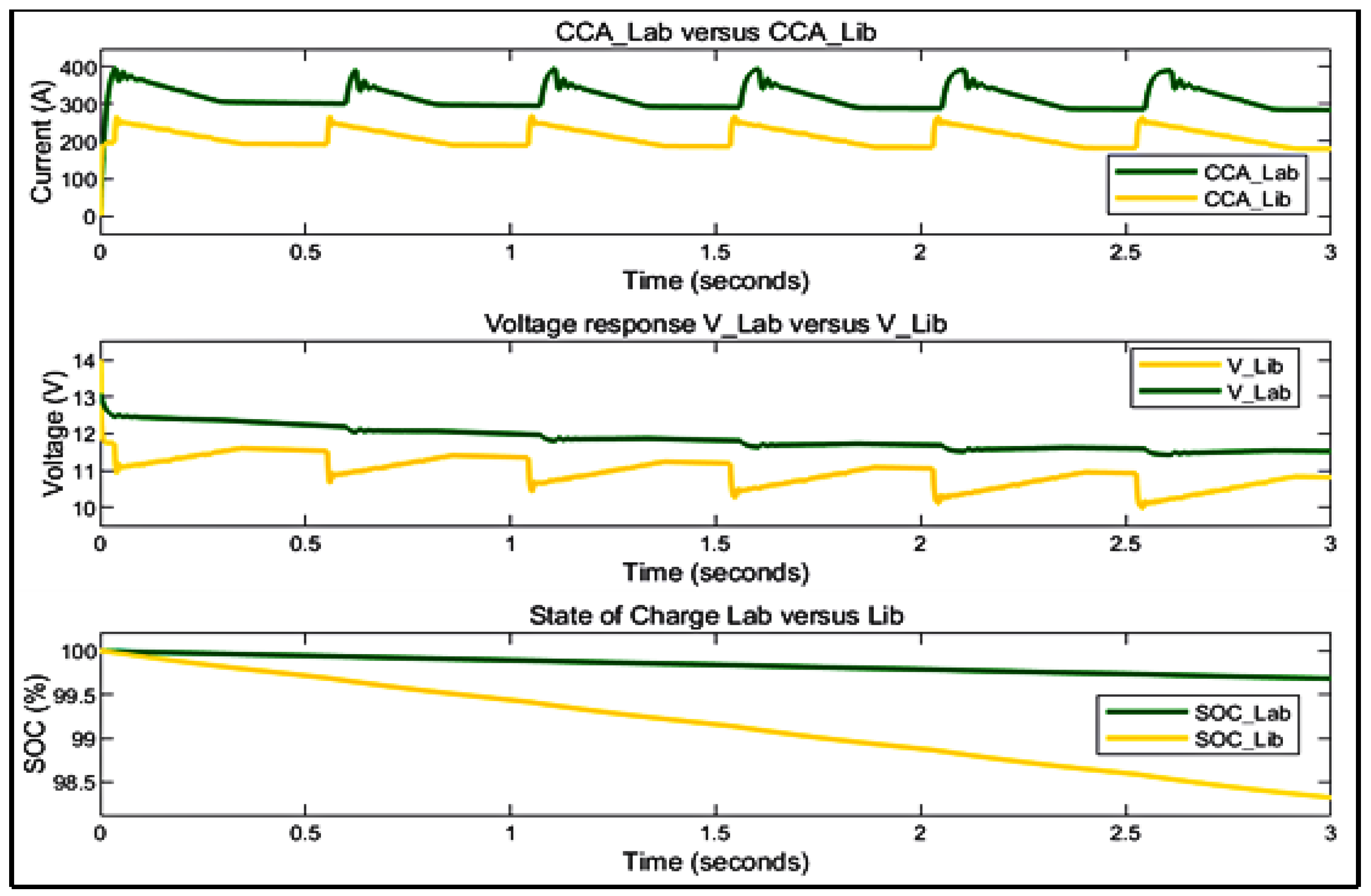
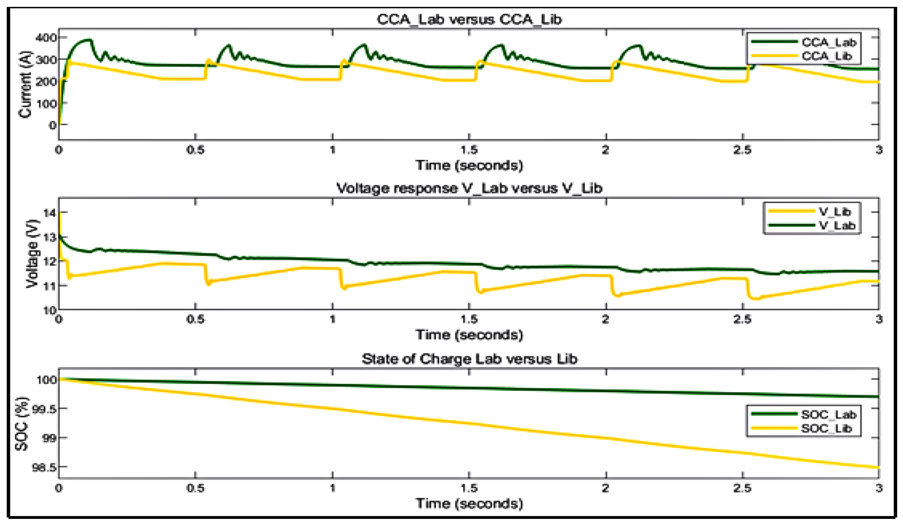
is the membership function during the start-up function, LAB supplied between 45% and 70% of the required startup current, and C C C L I B supplied about 30% to 70% depending on the operating scenario.
  • Zero is the mode when there is no action from the HESS, it means the HESS will not charge or discharge.
  • I ( C h L A B )   I ( C h L I B ) resembles the vehicle in running operation, where the alternator is producing more energy than required for the vehicle and the difference is used to charge the HESS. Decision-making rules are part of the fuzzy logic where the decisions are made. The rules and database are developed and defined to meet the desired output. Fuzzy logic control rules are represented by understanding and knowledge of human operators in the form of linguistic variables. It is normally represented as a sequence of the form “IF-THEN”, leading to algorithms describing what action or output should be taken inaction of the currently observed information, which includes both input and feedback if a closed-loop control system is applied [40,42]. FLC “IF-THEN” rule associates a condition defined using linguistic variables and fuzzy sets to obtain a certain output. “IF” is normally used to capture the knowledge by using elastic conditions. THEN is used to give the conclusion or output in linguistic variable form. These rules are normally used in fuzzy inference systems to compute the degree to which the input data match the condition of the rule, where:
    • IF C C A D e m a n d is equal to CCC and Δ S o C L A B   Δ S o C L I B are high, Then H E S S ( C C C R e f ) is equal to C C C H E S S (i.e., C L A B   C C C L I B ), which means the HESS will supply the required current, where each battery supplies the current based on the reference current given by the FLC.
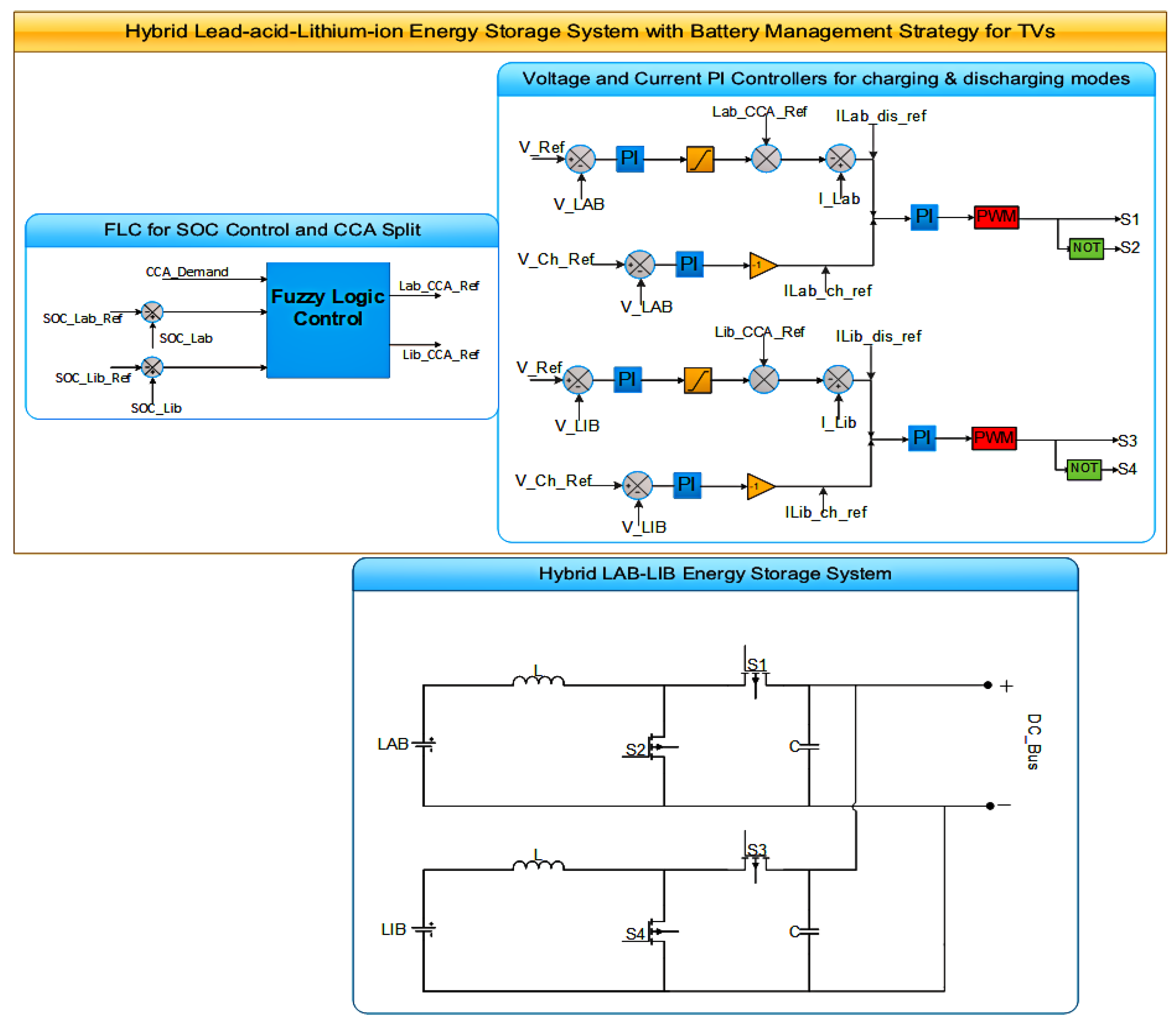
    • IF C C C D e m a n d = C C C and Δ S o C L A B   Δ S o C L I B are not high; Then H E S S ( C C C R e f ) is zero, which means that the system is balanced and HESS will not charge or discharge. Defuzzification: Defuzzification is the FLC output; it produces a quantifiable result in crisp logic based on the input membership, fuzzy rules and corresponding degrees processing fuzzy rules to a crisp set. The defuzzification method used in this proposed FLC is the centroid method. The FLC generate two outputs which are the percentage reference that which battery must supply. The output FLC reference is multiplied by the required CCC to form the reference CCC of each battery. The S o C C o m m a n d is used to give the reference SoC and to ensure the S o C H E S S within the limits, where the S o C ( L I B m i n ) = 98.5 % and S o C ( L I B m a x ) = 99.99 % . The S o C ( L A B m i n ) = 99.4 % and S o C ( L A B m a x ) = 100 % . Setting the SoC within limits helps guard against overcharging the battery, also deep release, along with avoiding keeping the LIB at full SoC by disconnecting the battery from the alternator. Figure 6 shows the proposed HESS with BMS for TVs. The batteries were connected in parallel and each connected in series with a bidirectional DC–DC buck-boost converter. The two converters’ output was connected to the DC-Bus.

3.4. Lifespan Estimation

The battery life prediction model used in this research study accumulates losses of battery based on discharge cycles. This type of module is called a fatigue model, which is one of the cycle counting approaches. Although the fatigue model is a high-level approximation for battery life, it is widely used due to its simplicity and clarity [46,47,48,49]. The fatigue models assume that each discharge of the battery affects battery degradation. For the proposed lifetime estimation, the following scenarios were considered and adopted as described in [37,50]:
  • From the battery datasheet, the curve showing the number of cycles of a battery as a function of DoD until it reaches the end of its lifetime was utilised.
  • The SoC represents the battery capacity in percentage.
  • The curve represents battery lifespan in days as a function of its float charging voltage and temperature. Therefore, based on the data obtained from [50], the loss-of-life (LoL) and maximum expected lifespan in years of batteries are estimated according to [46,47,49]. The LoL of the batteries is the sum over all types of operation during the observation period; it was estimated using the following Formula (21) as in [37]:
    L o L = i = 0 k N C ( i ) N C m a x
    where, i = { 0………… , k } = { 0 …… 100 % } , k is the battery DoD and stands for DoD and was used during the discharge operation mode. When DoD is 100%, it means that the battery is fully discharged. N c ( i ) represent the number of performed cycles at i th DoD, N c m a x is the number of cycles to failure, which was attained when 80% of the battery capacity was utilised [49]. Thus, the battery end-of-life (EoL) with several i th DoD was attained when the LoL was 1 [38,46,49,51]. This can further be formulated as: when N c ( i ) = N c m a x , then L o L = 1 . Hence, the battery lifespan is represented by the maximum number of services N ( m a x s ) of the battery, and represented by Equation (22) as in [37,47];
    N m a x s = 1 L o L ;
Additionally, if the vehicle serves several operations ( N o p ) in a day, then the maximum expected battery lifespan ( L s ) is represented by Equation (23) as in [37];
L s = N m a x s N o p × N c m a x 366 ( y e a r s )

4. Results and Discussions

This section describes the system modelling validation, presentation of results, and discussions thereof. The battery management strategy (BMS) ensures that the proposed solution meets the load demand for transport vehicles. The proposed research studies are analysed and compared with single lead-acid batteries. TVs are assumed to have starter motors that require a CCC of 590 A and 650 A for 3 s for the 12 V-70 Ah and 12 V-90 Ah batteries, respectively. Figure 7 show the generated cold-cranking demand required for case two and three.
As shown in Figure 7, the CCC required to crank the vehicle engine is 590 A for case two. Whereas for case three, the current is 650 A. These currents are supplied to crank the vehicle’s engine that uses a single LAB of 12 V-70 Ah and 12 V-90 Ah batteries. Therefore, these currents are supplied for only 3 s. Additionally, the HESS share the required cranking current between the individual ESSs while maintaining favourable operating conditions of these batteries such that the LABs’ lifespan can be preserved and extended.

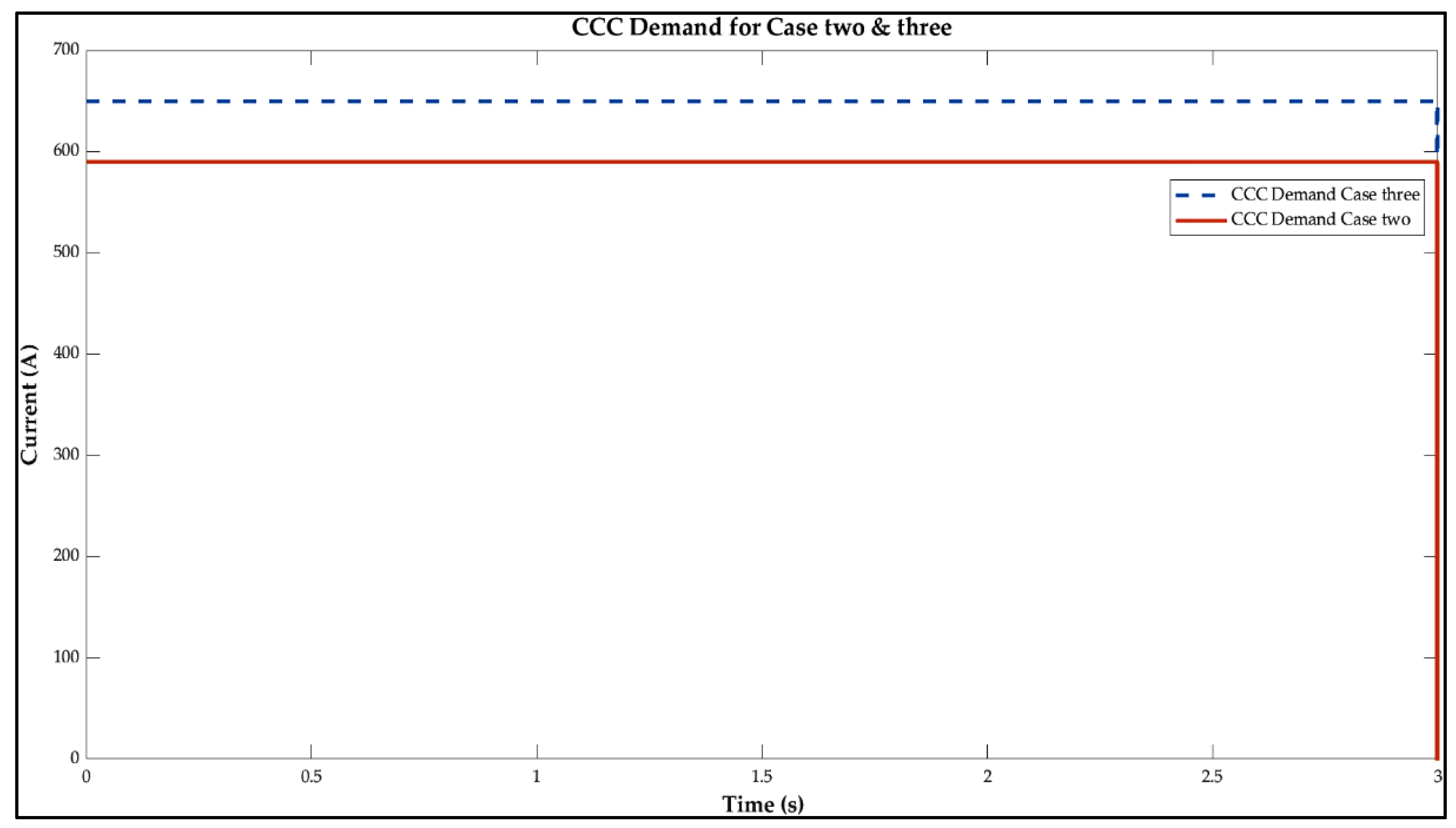
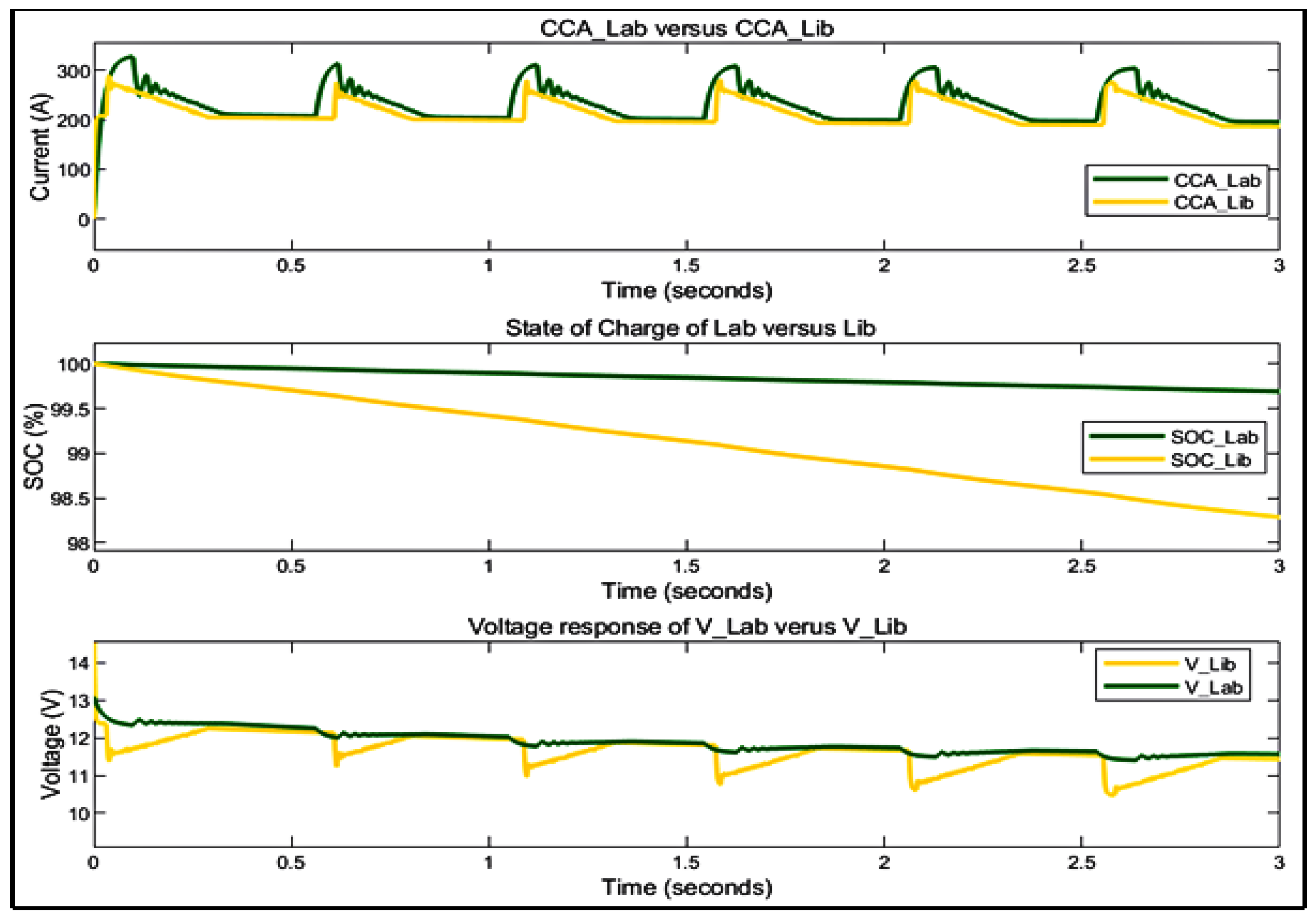
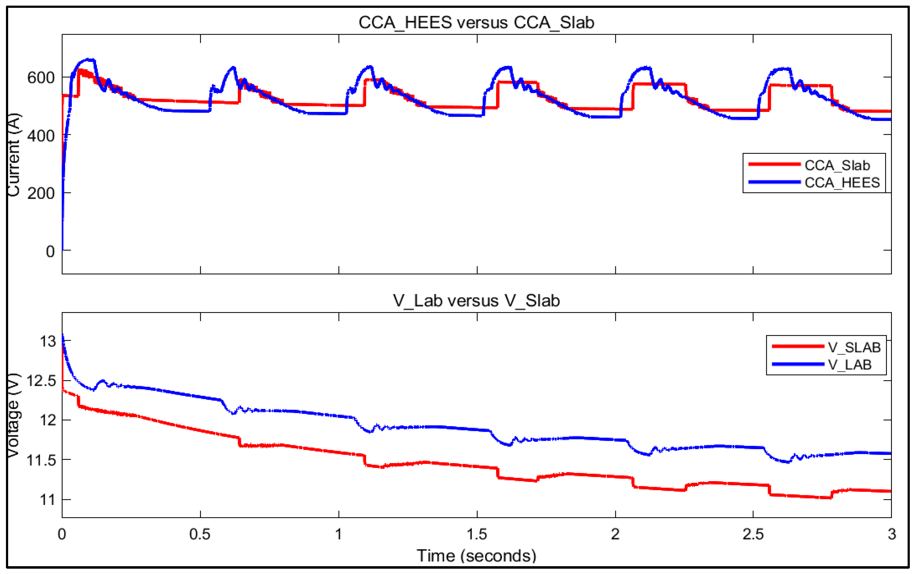
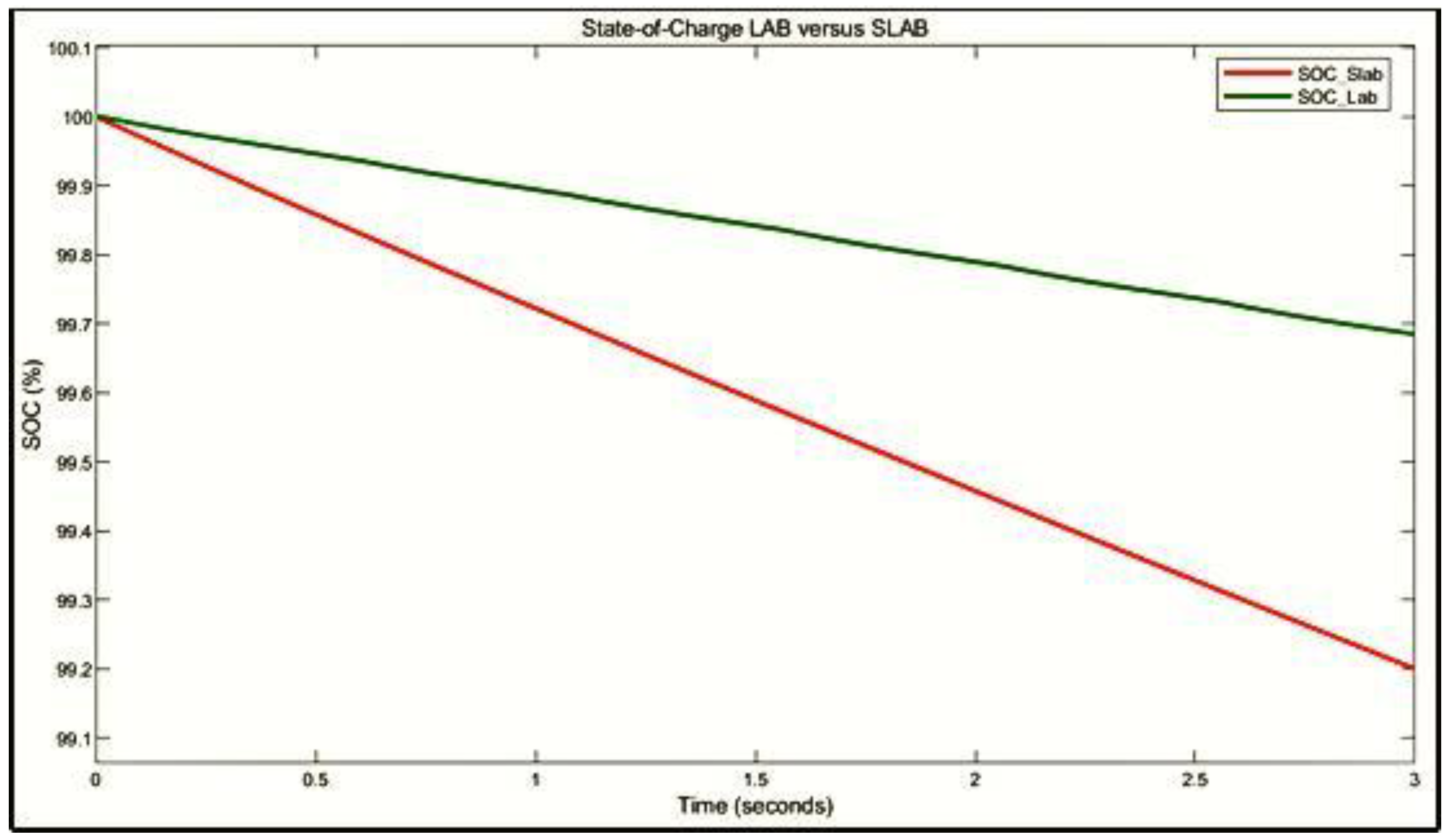
4.1. Case Two (12 V-70 Ah HESS Capacity)

The proposed HESS to supplement a 12 V-70 Ah single battery is analysed for 172 s in case two (a) and for 182 s in case two (b). This case study compares the attained results to a single LAB of the same size. Figure 7 and Figure 8 show the results of this case. Figure 8 illustrates the HESS delivering the maximum current required, which is 599.1 A for case two (a), while Figure 9 represents case two (b), where the HESS provides a maximum current of 596.2 A, respectively. The currents delivered by the HESS are more than the required CCC of 590 A for three seconds.
As shown in Figure 8 and Figure 9, the HESS supplies the required CCC. Furthermore, after three seconds, the CCC demand goes to zero, which illustrates that the engine is in running operation and no further demand is required. However, the HESS need to supply the vehicle auxiliary loads, but the study does not cover the energy needed to power up these auxiliary loads because it is beyond the scope of this research. Moreover, Figure 10 shows the LAB contribution for case two (a).
In Figure 10, LAB provides 326.9 A, which represents a contribution of 53% of the required CCC. The LAB voltage response results show a minimum voltage of 11.41 V, while the SoC remains at 99.69%. Consequently, LIB supplies 290.3 A of the required CCC, which is a 37.1% contribution. LIB voltage response recorded a minimum voltage of 9.51 V, and the SoC is retained at 98.09%. Figure 11 shows the results of the HESS for case two (b).
As shown in Figure 11, LAB supplies a portion of the required CCC, which is 378.5 A, thus accounting for 62.9% of the total CCC needed to crank the engine. The LAB minimum voltage response recorded was 11.31 V, and the SoC remained at 99.65%. Additionally, LIB provides 222.9 A of the required CCC, which accounts for 37.1%. The LIB minimum voltage response was 9.51 V, and the SoC remained at 98.09%. Moreover, the above results represent the discharging mode of the HESS. Thus, Figure 12 and Figure 13 show the charging behaviour of the HESS. In this mode, the HESS is simulated for 179 s for case two (a) and 169 s for case two (b).
In Figure 12, during HESS charging, LAB state-of-charge increases from 99.69% to 100%. Furthermore, the voltage response increases from 11.41 V to the charging reference voltage of 14.2 V and the charging reference current of −12 A. The LIB’s SoC increases from 98.28% to 99.9%, whereas the voltage response increases from 10.49 V to a charging reference voltage of 14.2 V with a charging reference current of −6 A. Figure 13 shows the results of case two (b) during the charging mode.
As shown in Figure 13, LAB’s SoC increases from 99.65% to 100%, whereas the voltage response increases from 11.31 V to the charging reference voltage of 13.1 V and the charging reference current of −13 A. The LIB’s SoC increases from 98.09% to 99.9%, whereas the voltage response increases from 9.51 V to the charging reference voltage of 14.2 V and the charging reference current of −5 A. The results show that when the batteries are fully charged, the charging current is 0 A, and the charging voltage reduces to the initial nominal battery voltage. Hence, compared with a single 12 V-70 Ah LAB during discharging mode for 3 s; it is clear from the results in Figure 14, which show that the proposed HESS delivers 599.1 A, whereas the minimum voltage is 11.41 V. While the SLAB delivers 538.1 A, with the minimum voltage being 10.97 V.
Figure 15 shows that the minimum LAB’s SoC after supplying CCC for 3 s is 99.69% and 99.24% for SLAB.

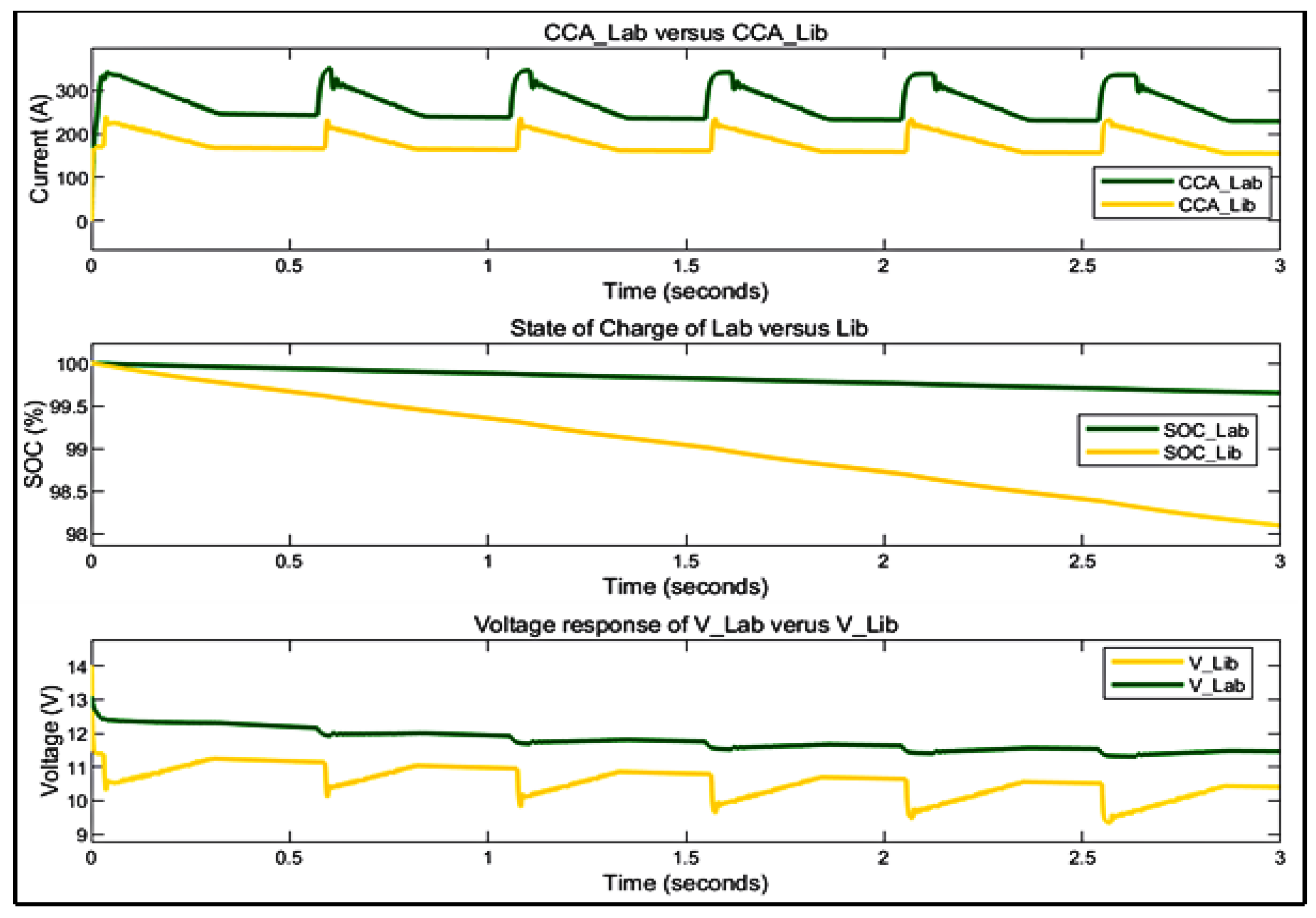
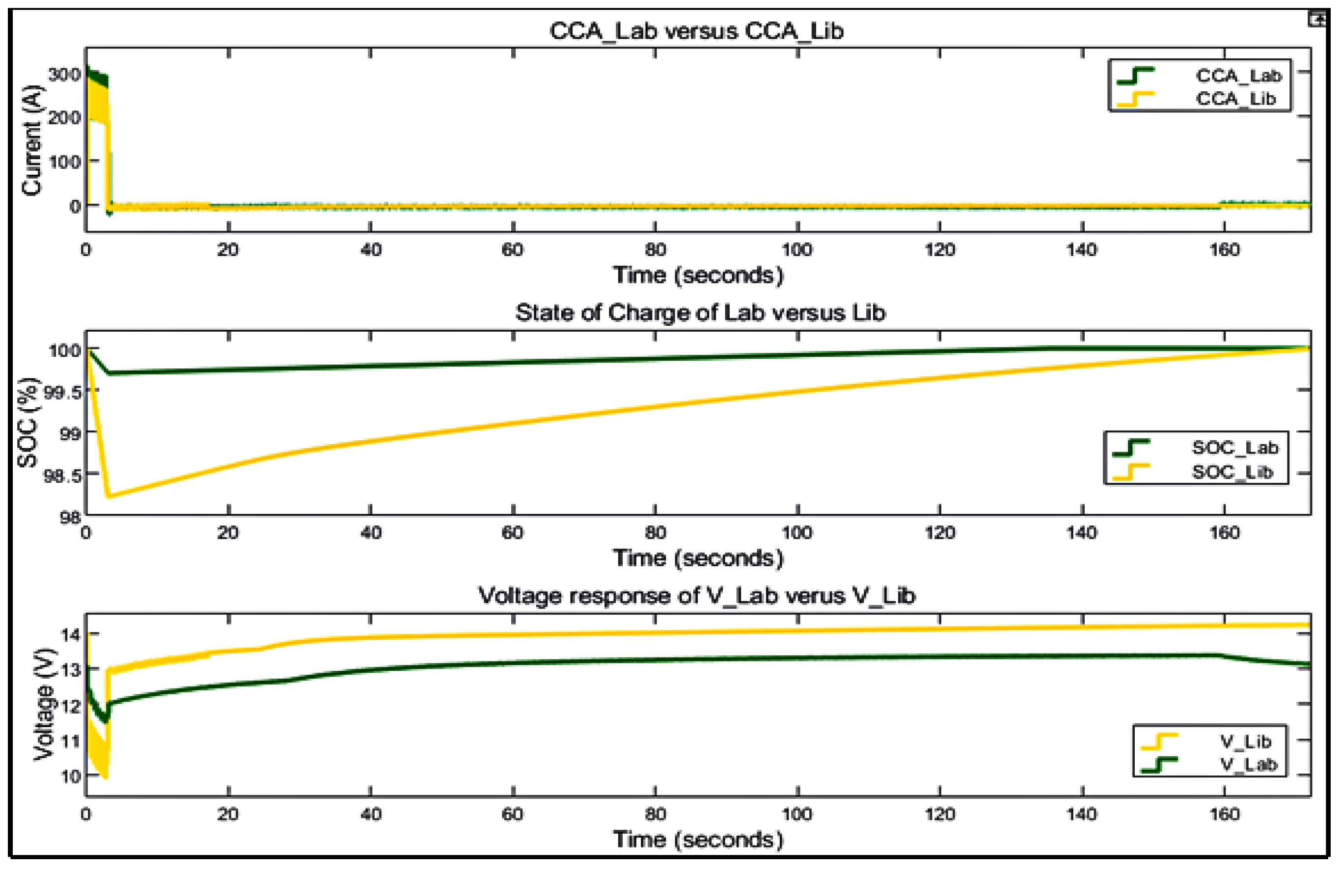
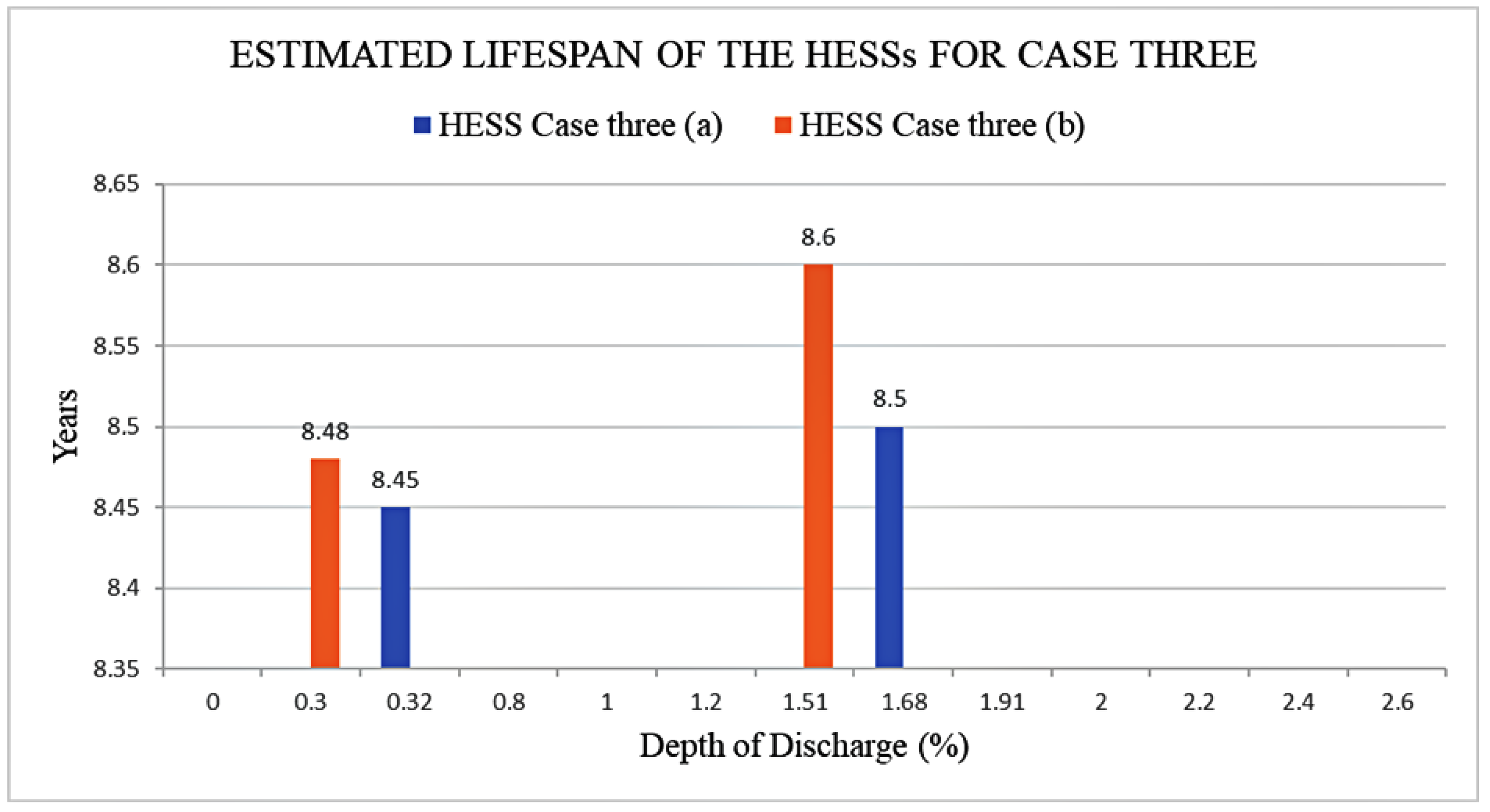
4.2. Case Three (12 V-90 Ah HESS Capacity)

In this case, the proposed HESS is simulated for 227 s for case three (a) and 234 s for case three (b), with required CCC ranges between 400 A and 650 A for 3 s. The proposed case three is compared with a single 12 V-90 Ah LAB with the same required CCC/A. Figure 16 and Figure 17 show the results of case three.
In Figure 16, the HESS delivers a maximum current of 653.2 A for case three (a). Figure 17 shows that the HESS delivers a maximum current of 665.5 A. These values are both greater than the required CCA of 650 A for 3 s.
As illustrated in Figure 16 and Figure 17, after three seconds, the CCA demand is 0 A. The results show that the HESS is charged with a maximum charging current of −21.1 A, which varies with the HESS’s SoC. The maximum charging voltage from the DC-bus link is 14.5 V. When the battery is fully charged, the current is 0 A, and the battery voltage reduce to the nominal battery voltage. The current supplied, SoC and voltage responses of the hybridised batteries during discharging mode are detailed herein. Figure 18 shows the results of case three (a) during discharging mode.
As shown in Figure 18, the LAB supplies 386.7 A for case three (a), which represents 59.68% of the required CCA, whereas the minimum voltage is 11.43 V and SoC is 98.32%. The LIB supplies 260.5 A, which represents 40.3% of the required CCA, whereas the minimum voltage is 9.985 V and SoC is 98.32%. Figure 19 shows the results of the HESS for case three (b).
In Figure 19, the LAB supplies 379.1 A, which represents 56.1% of the required CCA, whereas the minimum voltage is 11.47 V and SoC is 99.7. The LIB supplies 293.4 A, which represents the 43.9% required CCA, whereas the minimum voltage is 11.02 V and SoC is 98.49%. Moreover, Figure 20 and Figure 21 show the results of cases three (a) and (b) during charging modes. Case three (a) is simulated for 227 s, and case three (b) is for 234 s during charging mode.
In Figure 20, the LAB’s SoC starts from 99.68 to 100%, whereas the voltage response increases from 11.43 V to the charging reference voltage of 13.1 V and the charging reference current of −13 A. The LIB’s SoC starts from 98.32% to 99.9%, whereas the voltage response increases from 9.985 V to the charging reference voltage of 14.2 V and the charging reference current of −6 A. Figure 21 illustrate the results for case three (b).
As shown in Figure 21, the LAB’s SoC starts from 99.7 to 100%, whereas the voltage responses increase from 11.47 V to the charging reference voltage of 13.1 V and the charging reference current of −13 A. The LIB’s SoC starts from 98.49% to 99.9%, whereas the voltage response increases from 11.02 V to the charging reference voltage of 14.2 V and the charging reference current of −7 A. The results obtained in these cases are used to determine the lifespan of the system as compared to a single LAB. Therefore, compared with SLABs, the performance is analysed in terms of energy storage and lifespan. The comparison is made based on CCC delivered by the proposed HESS and SLABs, as well as the minimum SoC and voltage responses of LABs in HESS with SLABs during discharging mode to evaluate the delivery CCC and how it affects the SoC, voltage, and lifespan of the batteries. Figure 22 shows the results of case three as compared to a single LAB.
As shown in Figure 22, the proposed HESS is compared with a single 12 V-90 Ah during discharging mode for 3 s. It is clear from the results in Figure 22 that the proposed HESS delivers 653.2 A, whereas the minimum voltage is 11.43 V. While the SLAB delivers 631.7, whereas the minimum voltage is 10.64 V. Figure 23 shows that the LAB’s SoC after supplying the required CCA for 3 s is improved to 99.68% and 99.2% for SLAB.
As shown in Figure 23, the LAB SoC in a HESS is maintained at 99.7%, which demonstrates that it loses capacity slowly as compared to a single applied LAB.

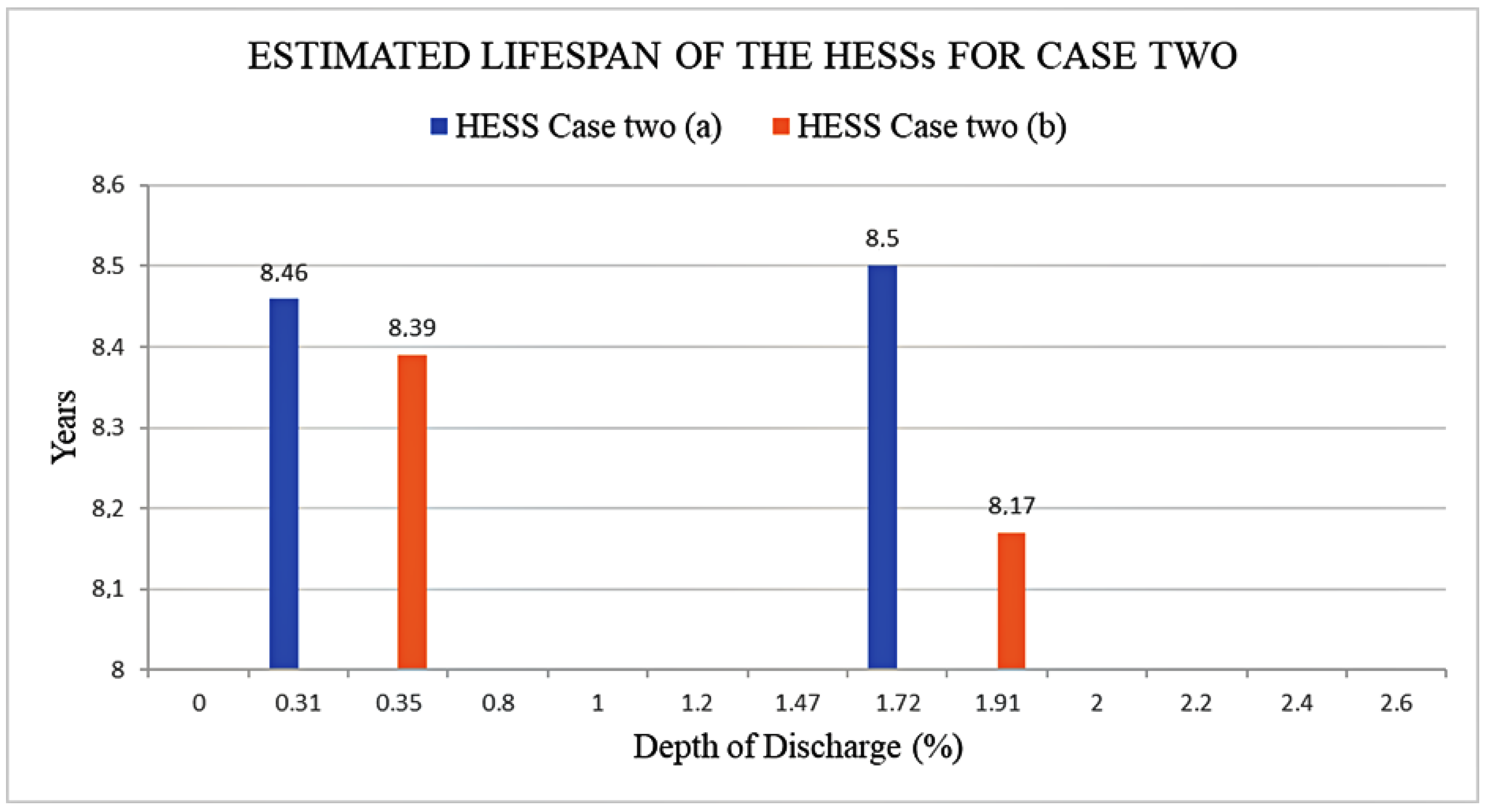
4.3. Lifespan Estimation Results

In this section, the lifespan of the battery is estimated and plotted based on the simulation results discussed above in all two cases. The results in datasheets as described in Section 3.4 are used as the reference for LAB and LIB, respectively. The battery lifespan is predicted based on assumptions of the battery having a maximum service per day of 30 and an average surrounding temperature of ± 25 . The evaluated system’s temperature is assumed to be kept at ±25 °C because, in the majority of ICEVs, the battery system is positioned such that constant airflow exists to cool the energy storage system. Hence, this study did not evaluate the system at different temperature values. In this study, the lifespan estimation using Equations (21)–(23) is obtained by considering the following:
  • On the battery datasheet, the curve showing the number of cycles as a function of DoD until the battery reaches EoL is used;
  • The curve shows the battery lifespan in days as a function of float charging voltage and temperature.
Thus, to estimate the lifespan, the study uses the extended life cycle graph of LAB with different DoD as indicated in [37]. Figure 24 shows the estimated lifespan results of the proposed HESS for case two.
In Figure 24, case two (a), the estimated lifespan of the hybridised batteries is 8.46 years for LAB and 8.5 years for LIB. For case two (b), the estimated lifespan for LAB is 8.39 years and 8.17 years for LIB. Figure 25 shows the estimated lifespan results for the proposed HESS for case three.
In Figure 25, case three (a), the estimated lifespan of the hybridised batteries is 8.45 years for LAB and 8.5 years for LIB. For case one (b), the estimated lifespan for LAB is 8.48 years and 8.6 years for LIB. Case two (a) and Case three (a) have excellent performance in terms of delivered CCC, voltage, and estimated lifespan of 8.49 and 8.4 years while costing less compared with case two (b) and case three (b).
Furthermore, the lifespan of the LAB is estimated and compared with SLAB. The proposed HESS also improves the LABs in terms of storage capacity by 10.18% and lifespan by 3.49 years for case two and by 3.3%, and lifespan by 3.5 years for case three. Additionally, the results indicate that when the LAB SoC is above 99.65%, it can significantly improve the lifespan by more than three years.
The supply of the required cold cranking current to start the vehicle, which is between 100 and 800 A for 3 s, and maintain the battery voltage above 7.2 V, while the battery DoD is between 1 to 3%. The battery’s lifespan is affected by the DoD. To improve the battery lifespan, the battery SoC must be kept as high as possible. Thus, DoD will be less.
Although LIBs as a single source for SLI applications are available in the market [5], the HESS performance is superior to these LIBs. In [52], the algorithm for LIB capability to crank the vehicle’s engine is developed. Nevertheless, the algorithm shows less efficacy, and mathematical equations are heavy for computation. Table 2 shows the summary of the results for both cases.

5. Conclusions

The study evaluates LABs performance for TVs in terms of storage capacity and lifespan without changing the current chemical composition of the batteries. The results show that the proposed integrated fuzzy-logic and Triple-loop PI-based control battery management strategy for lead-acid and lithium-ion hybrid battery energy storage systems; improves the batteries’ performance in terms of storage capacity and lifespan. The fuzzy logic control is used to allocate the reference current within the hybridised batteries and to ensure the state of charge of hybridised batteries is within the permissible maximum and minimum limits. The results show that the FLC is capable of allocating the required reference current within a margin of ± 2 % . The bidirectional DC–DC buck-boost converter with a triple-loop PI-based controller is used to control the voltage and current flow of the hybridised batteries during charging and discharging modes based on the reference voltage and current. The results show an enhancement of storage capacity and lifespan of the proposed 12 V-70 Ah HESS of 10.18% and 3.49 years, respectively, in comparison with single a 12 V-70 Ah LAB. The results of case three show an enhancement of storage capacity and lifespan for the proposed 12 V-90 Ah HESS is 3.3% and 3.5 years, respectively, in comparison with a single 12 V-90 Ah LAB.

Author Contributions

Conceptualization, M.J.L., S.P.D.C. and T.O.O.; methodology, M.J.L., A.T.P.Z., S.P.D.C. and T.O.O.; software, M.J.L., A.T.P.Z., S.P.D.C. and T.O.O.; validation, M.J.L., S.P.D.C. and T.O.O.; formal analysis, M.J.L., S.P.D.C. and T.O.O.; investigation, M.J.L., A.T.P.Z., S.P.D.C. and T.O.O.; resources, M.J.L.; data curation, M.J.L., A.T.P.Z., S.P.D.C. and T.O.O.; writing—original draft preparation, M.J.L.; writing—review and editing, M.J.L., S.P.D.C. and T.O.O.; visualization, M.J.L., A.T.P.Z., S.P.D.C. and T.O.O.; supervision, S.P.D.C. and T.O.O.; project administration, M.J.L. All authors have read and agreed to the published version of the manuscript.

Funding

This research received no external funding.

Institutional Review Board Statement

Not applicable.

Informed Consent Statement

Not applicable.

Data Availability Statement

Not applicable.

Acknowledgments

The authors would like to thank the S5 Enterprises, Tshwane University of Technology, Au-toX (Pty) Ltd., South Africa for providing the necessary infrastructure, resources and support tosuccessfully conduct this research study.

Conflicts of Interest

The authors declare no conflict of interest.

Nomenclature

C 1 C 2 Parallel branch capacitances.
C C C / A Cold-cranking current/ampere.
C C C H E S S Hybrid energy storage system cold cranking current.
C C C L A B Lead-acid battery cold cranking current.
C C C L I B Li-ion battery cold cranking current.
C m i n Minimum converter output capacitance.
D Duty cycle.
D o D Depth of discharge.
E o L End of life.
f s Switching frequency.
H E S S C C C r e f Reference cold cranking current of a hybrid energy storage system.
I A l t Alternator current.
I A u x Required auxiliary components current.
i b Battery charging current.
i c Battery circulating current.
I c h r e f Reference charging current.
I D e m a n d Demanded output current.
i L m Inductor current.
Δ i L m i n Change in minimum inductor current.
i o Converter output cold cranking current.
k Battery depth of discharge.
L m i n Minimum inductor value.
L o L Loss of battery life.
N c ( i ) The number of cycles performed at instant i .
N c m a x The maximum number of cycles to failure.
N m a x s The maximum number of battery services.
N o p The number of operations.
O C V Open circuit voltage.
ρ PI control compensation factor.
Q b Actual battery capacity.
Q s Stored battery capacity.
R 1 R 2 Parallel branch resistances.
R s Internal battery series resistance.
S L A B Single lead-acid battery.
S o C State of charge.
S o C H E S S Hybrid energy storage system state of charge.
S o C i n i t Initial battery state of charge.
S o C L A B Lead-acid battery state of charge.
S o C L I B Li-ion battery state of charge.
S o C ( L A B m i n ) Minimum lead-acid battery state of charge.
S o C ( L A B m a x ) Maximum lead-acid battery state of charge.
S o C ( L I B m i n ) Minimum li-ion battery state of charge.
S o C ( L I B m a x ) Maximum li-ion battery state of charge.
Δ S o C L A B Change in lead-acid battery state of charge.
Δ S o C L I B Change in li-ion battery state of charge.
T Sampling time.
V Total voltage drops in the RC parallel branch.
V b / b a t t Battery voltage.
V c h r e f Charging battery reference voltage.
V D C B u s DC bus voltage link.
V H High inductor voltage.
V L Low inductor voltage.
V L m i n Minimum inductor voltage.
V o Converter output voltage.
Δ V o Change in converter output voltage.
V r e f Reference voltage.
V s Battery internal resistance voltage drop.

References

  1. Leach, F.; Kalghatgi, G.; Stone, R.; Miles, P. The Scope for Improving the Efficiency and Environmental Impact of Internal Combustion Engines. Transp. Eng. 2020, 1, 100005. [Google Scholar] [CrossRef]
  2. Electric Cars Fend off Supply Challenges to More than Double Global Sales—Analysis. Available online: https://www.iea.org/commentaries/electric-cars-fend-off-supply-challenges-to-more-than-double-global-sales (accessed on 7 February 2022).
  3. Balali, Y.; Stegen, S. Review of Energy Storage Systems for Vehicles Based on Technology, Environmental Impacts, and Costs. Renew. Sustain. Energy Rev. 2021, 135, 110185. [Google Scholar] [CrossRef]
  4. Kollmeyer, P.J.; Jahns, T.M. Aging and Performance Comparison of Absorbed Glass Matte, Enhanced Flooded, PbC, NiZn, and LiFePO4 12 V Start Stop Vehicle Batteries. J. Power Sources 2019, 441, 227139. [Google Scholar] [CrossRef]
  5. Ferg, E.E.; Schuldt, F.; Schmidt, J. The Challenges of a Li-Ion Starter Lighting and Ignition Battery: A Review from Cradle to Grave. J. Power Sources 2019, 423, 380–403. [Google Scholar] [CrossRef]
  6. Albers, J.; Meissner, E. 6—Automotive Absorptive Glass-Mat Lead–Acid Batteries: State of the Art. In Lead-Acid Batteries for Future Automobiles; Garche, J., Karden, E., Moseley, P.T., Rand, D.A.J., Eds.; Elsevier: Amsterdam, The Netherlands, 2017; pp. 185–211. ISBN 978-0-444-63700-0. [Google Scholar]
  7. Dehghani-Sanij, A.R.; Tharumalingam, E.; Dusseault, M.B.; Fraser, R. Study of Energy Storage Systems and Environmental Challenges of Batteries. Renew. Sustain. Energy Rev. 2019, 104, 192–208. [Google Scholar] [CrossRef]
  8. Moseley, P.T.; Rand, D.A.J.; Garche, J. Study of Energy Storage Systems and Environmental Challenges of Batteries. In Lead-Acid Batteries for Future Automobiles; Garche, J., Karden, E., Moseley, P.T., Rand, D.A.J., Eds.; Elsevier: Amsterdam, The Netherlands, 2017; pp. 601–618. ISBN 978-0-444-63700-0. [Google Scholar]
  9. Srinivas, S.; Hiremath, N.; Reddy, K.C. Energy Requirement of Hybrid Vehicles. Mater. Today Proc. 2021, 54, 282–287. [Google Scholar] [CrossRef]
  10. Mandal, S.; Thangarasu, S.; Thong, P.T.; Kim, S.-C.; Shim, J.-Y.; Jung, H.Y. Positive Electrode Active Material Development Opportunities through Carbon Addition in the Lead-Acid Batteries: A Recent Progress. J. Power Sources 2021, 485, 229336. [Google Scholar] [CrossRef]
  11. Shi, M.; Yuan, J.; Dong, L.; Zhang, D.; Li, A.; Zhang, J. Combining Physicochemical Model with the Equivalent Circuit Model for Performance Prediction and Optimization of Lead-Acid Batteries. Electrochim. Acta 2020, 353, 136567. [Google Scholar] [CrossRef]
  12. Hu, X.; Zou, C.; Zhang, C.; Li, Y. Technological Developments in Batteries: A Survey of Principal Roles, Types, and Management Needs. IEEE Power Energy Mag. 2017, 15, 20–31. [Google Scholar] [CrossRef]
  13. Lencwe, M.J.; Chowdhury, S.P.D.; Olwal, T.O. Performance Studies of Lead Acid Batteries for Transport Vehicles. In Proceedings of the 2017 IEEE PES PowerAfrica, Accra, Ghana, 27–30 June 2017; pp. 528–532. [Google Scholar]
  14. Zhang, Y.; Zhou, C.; Yang, J.; Xue, S.; Gao, H.; Yan, X.; Huo, Q.; Wang, S.; Cao, Y.; Yan, J.; et al. Advances and Challenges in Improvement of the Electrochemical Performance for Lead-Acid Batteries: A Comprehensive Review. J. Power Sources 2022, 520, 230800. [Google Scholar] [CrossRef]
  15. Chen, C.; Liu, Y.; Chen, Y.; Li, X.; Cheng, J.; Chen, S.; Lin, J.; Zhang, X.; Zhang, Y. Effect of Polyaniline-Modified Lignosulfonate Added to the Negative Active Material on the Performance of Lead-Acid Battery. Electrochim. Acta 2020, 338, 135859. [Google Scholar] [CrossRef]
  16. Zhang, Y.; Ali, A.; Li, J.; Xie, J.; Shen, P.K. Stereotaxically Constructed Graphene/Nano Lead Composite for Enhanced Cycling Performance of Lead-Acid Batteries. J. Energy Storage 2021, 35, 102192. [Google Scholar] [CrossRef]
  17. Calborean, A.; Murariu, T.; Morari, C. Optimized Lead-Acid Grid Architectures for Automotive Lead-Acid Batteries: An Electrochemical Analysis. Electrochim. Acta 2021, 372, 137880. [Google Scholar] [CrossRef]
  18. Fichtner, M. Recent Research and Progress in Batteries for Electric Vehicles. Batter. Supercaps 2022, 5, e202100224. [Google Scholar] [CrossRef]
  19. Ding, Y.; Cano, Z.P.; Yu, A.; Lu, J.; Chen, Z. Automotive Li-Ion Batteries: Current Status and Future Perspectives. Electrochem. Energy Rev. 2019, 2, 1–28. [Google Scholar] [CrossRef]
  20. Chen, W.; Liang, J.; Yang, Z.; Li, G. A Review of Lithium-Ion Battery for Electric Vehicle Applications and Beyond. Energy Procedia 2019, 158, 4363–4368. [Google Scholar] [CrossRef]
  21. Sanguesa, J.A.; Torres-Sanz, V.; Garrido, P.; Martinez, F.J.; Marquez-Barja, J.M. A Review on Electric Vehicles: Technologies and Challenges. Smart Cities 2021, 4, 372–404. [Google Scholar] [CrossRef]
  22. Kebede, A.A.; Coosemans, T.; Messagie, M.; Jemal, T.; Behabtu, H.A.; Van Mierlo, J.; Berecibar, M. Techno-Economic Analysis of Lithium-Ion and Lead-Acid Batteries in Stationary Energy Storage Application. J. Energy Storage 2021, 40, 102748. [Google Scholar] [CrossRef]
  23. Cano, Z.P.; Banham, D.; Ye, S.; Hintennach, A.; Lu, J.; Fowler, M.; Chen, Z. Batteries and Fuel Cells for Emerging Electric Vehicle Markets. Nat. Energy 2018, 3, 279–289. [Google Scholar] [CrossRef]
  24. Deng, J.; Bae, C.; Denlinger, A.; Miller, T. Electric Vehicles Batteries: Requirements and Challenges. Joule 2020, 4, 511–515. [Google Scholar] [CrossRef]
  25. Hannan, M.A.; Hoque, M.M.; Hussain, A.; Yusof, Y.; Ker, P.J. State-of-the-Art and Energy Management System of Lithium-Ion Batteries in Electric Vehicle Applications: Issues and Recommendations. IEEE Access 2018, 6, 19362–19378. [Google Scholar] [CrossRef]
  26. Omariba, Z.B.; Zhang, L.; Sun, D. Review on Health Management System for Lithium-Ion Batteries of Electric Vehicles. Electronics 2018, 7, 72. [Google Scholar] [CrossRef] [Green Version]
  27. Trahey, L.; Brushett, F.R.; Balsara, N.P.; Ceder, G.; Cheng, L.; Chiang, Y.-M.; Hahn, N.T.; Ingram, B.J.; Minteer, S.D.; Moore, J.S.; et al. Energy Storage Emerging: A Perspective from the Joint Center for Energy Storage Research. Proc. Natl. Acad. Sci. USA 2020, 117, 12550–12557. [Google Scholar] [CrossRef] [PubMed]
  28. Lencwe, M.J.; Chowdhury, S.P.D.; Olwal, T.O. Hybrid Energy Storage System Topology Approaches for Use in Transport Vehicles: A Review. Energy Sci. Eng. 2022, 10, 1449–1477. [Google Scholar] [CrossRef]
  29. Nizam, M.; Maghfiroh, H.; Nur Kuncoro, F.; Adriyanto, F. Dual Battery Control System of Lead Acid and Lithium Ferro Phosphate with Switching Technique. World Electr. Veh. J. 2021, 12, 4. [Google Scholar] [CrossRef]
  30. Yu, X.; Sandhu, N.S.; Yang, Z.; Zheng, M. Suitability of Energy Sources for Automotive Application—A Review. Appl. Energy 2020, 271, 115169. [Google Scholar] [CrossRef]
  31. Kalghatgi, G. Development of Fuel/Engine Systems—The Way Forward to Sustainable Transport. Engineering 2019, 5, 510–518. [Google Scholar] [CrossRef]
  32. Singh, A.; Karandikar, P.B.; Kulkarni, N.R. Mitigation of Sulfation in Lead Acid Battery towards Life Time Extension Using Ultra Capacitor in Hybrid Electric Vehicle. J. Energy Storage 2021, 34, 102219. [Google Scholar] [CrossRef]
  33. Farjah, A.; Ghanbari, T.; Seifi, A.R. Contribution Management of Lead-acid Battery, Li-ion Battery, and Supercapacitor to Handle Different Functions in EVs. Int. Trans. Electr. Energy Syst. 2020, 30, e12155. [Google Scholar] [CrossRef]
  34. Lencwe, M.J.; Chowdhury, S.P.; Olwal, T.O. A Multi-Stage Approach to a Hybrid Lead Acid Battery and Supercapacitor System for Transport Vehicles. Energies 2018, 11, 2888. [Google Scholar] [CrossRef] [Green Version]
  35. Lencwe, M.J.; Chowdhury, S.P.D.; Olwal, T.O. An Effective Control for Lead-Acid Performance Enhancement in a Hybrid Battery-Supercapacitor System Used in Transport Vehicles. Sustainability 2021, 13, 13971. [Google Scholar] [CrossRef]
  36. Madani, S.S.; Schaltz, E.; Knudsen Kær, S. An Electrical Equivalent Circuit Model of a Lithium Titanate Oxide Battery. Batteries 2019, 5, 31. [Google Scholar] [CrossRef] [Green Version]
  37. Zau, A.T.P.; Lencwe, M.J.; Chowdhury, S.P.D.; Olwal, T.O. A Battery Management Strategy in a Lead-Acid and Lithium-Ion Hybrid Battery Energy Storage System for Conventional Transport Vehicles. Energies 2022, 15, 2577. [Google Scholar] [CrossRef]
  38. Fiorenti, S.; Guanetti, J.; Onori, S.; Guezennec, Y.; Madella, N.; Saletti, A.; Bovo, S. Modeling and Experimental Validation of PbA Battery-Supercapacitor Energy Storage System. IFAC Proc. Vol. 2013, 46, 307–312. [Google Scholar] [CrossRef]
  39. Iskak, C.A.; Windarko, N.A.; Rakhmawati, R. Design and Implementation Bidirectional DC-DC Converter for Load Sharing and Charging Battery. In Proceedings of the 2019 International Seminar on Application for Technology of Information and Communication (iSemantic), Semarang, Indonesia, 21–22 September 2019; pp. 455–459. [Google Scholar]
  40. Chao, K.H.; Tseng, M.C.; Huang, C.H.; Liu, Y.G.; Huang, L.C. Design and Implementation of a Bidirectional DC-DC Converter for Stand-Alone Photovoltaic Systems. Int. J. Comput. Consum. Control IJ3C 2013, 2, 44–55. [Google Scholar]
  41. Ceraolo, M.; Huria, T.; Pede, G.; Vellucci, F. Lithium-Ion Starting-Lighting-Ignition Batteries: Examining the Feasibility. In Proceedings of the 2011 IEEE Vehicle Power and Propulsion Conference, Chicago, IL, USA, 6–9 September 2011; pp. 1–6. [Google Scholar]
  42. Bai, Y.; Wang, D. Fundamentals of Fuzzy Logic Control—Fuzzy Sets, Fuzzy Rules and Defuzzifications. In Advanced Fuzzy Logic Technologies in Industrial Applications; Springer: Berlin/Heidelberg, Germany, 2006; pp. 17–36. [Google Scholar]
  43. Jadhav, A.D.; Nair, S. Battery Management Using Fuzzy Logic Controller. J. Phys. Conf. Ser. 2019, 1172, 012093. [Google Scholar] [CrossRef]
  44. Ross, T.J. Fuzzy Logic with Engineering Applications; John Wiley & Sons: Hoboken, NJ, USA, 2005; ISBN 0-470-86076-6. [Google Scholar]
  45. Sun, Q.; Xing, D.; Yang, Q.; Zhang, H.; Patel, J. A New Design of Fuzzy Logic Control for SMES and Battery Hybrid Storage System. In Proceedings of the 8th International Conference on Applied Energy—ICAE2016, Beijing, China, 8–11 October 2016. [Google Scholar] [CrossRef]
  46. Andrenacci, N.; Chiodo, E.; Lauria, D.; Mottola, F. Life Cycle Estimation of Battery Energy Storage Systems for Primary Frequency Regulation. Energies 2018, 11, 3320. [Google Scholar] [CrossRef] [Green Version]
  47. Jeong, S.; Jang, Y.J.; Kum, D. Economic Analysis of the Dynamic Charging Electric Vehicle. IEEE Trans. Power Electron. 2015, 30, 6368–6377. [Google Scholar] [CrossRef]
  48. Sauer, D.U.; Wenzl, H. Comparison of Different Approaches for Lifetime Prediction of Electrochemical Systems—Using Lead-Acid Batteries as Example. J. Power Sources 2008, 176, 534–546. [Google Scholar] [CrossRef]
  49. Schaltz, E.; Khaligh, A.; Rasmussen, P.O. Influence of Battery/Ultracapacitor Energy-Storage Sizing on Battery Lifetime in a Fuel Cell Hybrid Electric Vehicle. IEEE Trans. Veh. Technol. 2009, 58, 3882–3891. [Google Scholar] [CrossRef]
  50. ForbattSA. Forbatt 12 V VRLA 70 AH FB12-70. 2021. Available online: https://forbatt.co/shop/uncategorized/forbatt-installations-accessories/intrusion-accessories-forbatt-installations-accessories/motorcylce-batteries/forbatt12v-vrla-70ahfb12-70/ (accessed on 24 January 2022).
  51. Meissner, E.; Richter, G. The Challenge to the Automotive Battery Industry: The Battery Has to Become an Increasingly Integrated Component within the Vehicle Electric Power System. J. Power Sources 2005, 144, 438–460. [Google Scholar] [CrossRef]
  52. Noh, T.-W.; Ahn, J.-H.; Lee, B.K. Cranking Capability Estimation Algorithm Based on Modeling and Online Update of Model Parameters for Li-Ion SLI Batteries. Energies 2019, 12, 3365. [Google Scholar] [CrossRef] [Green Version]
Figure 1. Battery equivalent circuit model with 2nd-order RC branch, Reproduced from [37].
Applsci 12 06910 g001
Figure 2. A bidirectional DC–DC buck–boost converter equivalent circuit model.
Applsci 12 06910 g002
Figure 3. Logic flow chart of the proposed rule-based BMS for HESS during charging mode operation, Reproduced from [37].
Applsci 12 06910 g003
Figure 4. Logic flow chart of the proposed rule-based BMS for HESS during discharging mode operation, Reproduced from [37].
Applsci 12 06910 g004
Figure 5. Experimental procedure for the developed HESS.
Applsci 12 06910 g005
Figure 6. Proposed hybrid energy storage system for ICEVs.
Applsci 12 06910 g006
Figure 7. Generated cold cranking current or ampere demand required to crank the engine.
Applsci 12 06910 g007
Figure 8. The CCC is supplied by the HESS for case two (a).
Applsci 12 06910 g008
Figure 9. The CCC is supplied by the HESS for case two (b).
Applsci 12 06910 g009
Figure 10. LAB and LIB contribution to CCC, SoC and voltage response during discharge for case two (a).
Applsci 12 06910 g010
Figure 11. LAB and LIB contribution to CCC, SoC and voltage response during discharge for case two (b).
Applsci 12 06910 g011
Figure 12. CCC contribution, SoC and voltage response of HESS during discharging and charging modes for case two (a).
Applsci 12 06910 g012
Figure 13. Required CCA, SoC and voltage response of HESS during charging mode for case two (b).
Applsci 12 06910 g013
Figure 14. The delivered HESS CCC versus SLAB and voltage response of LAB versus SLAB during discharging modes for case two.
Applsci 12 06910 g014
Figure 15. The SoC of LAB in a HESS versus SLAB during discharging modes for case two.
Applsci 12 06910 g015
Figure 16. HESS supplying the required CCC for case three (a).
Applsci 12 06910 g016
Figure 17. HESS supplying the required CCC for case three (b).
Applsci 12 06910 g017
Figure 18. The supplied required CCC, SoC and voltage response of HESS for case three (a) during discharge mode.
Applsci 12 06910 g018
Figure 19. The supplied required CCC, SoC and voltage response of HESS for case three (b) during discharge mode.
Applsci 12 06910 g019
Figure 20. The CCC, SoC and voltage response of HESS during charging mode for case three (a).
Applsci 12 06910 g020
Figure 21. The CCC, SoC and voltage response of HESS during charging mode for case three (b).
Applsci 12 06910 g021
Figure 22. The delivered CCC by HESS versus SLAB, and voltage response of LAB versus SLAB during discharging mode for case three.
Applsci 12 06910 g022
Figure 23. The SoC of the LAB in a HESS versus SLAB during discharging mode for case three.
Applsci 12 06910 g023
Figure 24. The estimated lifespan of Case two (a) versus Case two (b).
Applsci 12 06910 g024
Figure 25. The estimated lifespan of case three (a) versus Case three (b).
Applsci 12 06910 g025
Table 1. Summary of converter parameters for battery capacities under study.
12 V-70 Ah Battery
Battery TypeBoost ModeBuck Mode
Vbatt (V)VDC_OUT (V)Lmin (nH)CminDboostDbuckVbus (V)Vchar (V)
LAB12.27331358.412.2 mF0.0560.914.513.1
LIB12.79541311.38871 µF0.0160.9714.514.2
12 V-90 Ah Battery
LAB12.27331353.022.4 mF0.0560.914.513.1
LIB12.7954131.03960 µF0.0160.9714.514.2
Table 2. A summary of the HESS case results.
Case No.Battey TypeCapacity (Ah)CCC (A)Load Share (%)
TwoaHESS70.4599.1100
LAB60326.953
LIB7.8290.347
bHESS69.8596.2100
LAB62378.562.9
LIB10.4222.937.1
ThreeaHESS90.4653.2-
LAB80386.759.7
LIB10.4260.540.3
bHESS90665.5100
LAB77379.156.1
LIB13293.443.9
Publisher’s Note: MDPI stays neutral with regard to jurisdictional claims in published maps and institutional affiliations.

