
Model for Wall Shear Stress from Obliquely Impinging Planar Underexpanded Jets


1
Department of Neurological Surgery, University of Washington, Seattle, WA 98105, USA
2
Department of Mechanical Engineering, University of Washington, Seattle, WA 98105, USA
*
Author to whom correspondence should be addressed.
Appl. Sci. 2022, 12(14), 7311; https://0-doi-org.brum.beds.ac.uk/10.3390/app12147311
Submission received: 30 June 2022
/
Revised: 15 July 2022
/
Accepted: 19 July 2022
/
Published: 21 July 2022
(This article belongs to the Topic Fluid Mechanics)
Abstract
:Though inclined under-expanded planar jets are used in many practical applications, the wall stress resulting from their impingement has not been adequately characterized. Reduced-order models for wall shear as a function of jet parameters have not been reported. This work uses computational fluid dynamics to determine wall shear stress as a function of the nozzle parameters and jet angle. The simulations of the impinging jet are validated against the experimental data and direct numerical simulation; then, the jet parameters are varied to formulate an empirical relationship for maximum wall shear stress as a function of a nozzle pressure ratio, standoff distance, jet Reynolds number, and impingement angle. The global expression for shear stress agrees with the numerical results within a mean deviation of 3%. The relationship can be used for applications where shear stress information is required to design or assess the performance of practical systems, such as surface cleaning, particle resuspension from the surface, and surface cooling.
1. Introduction
Impinging jets have a wide range of scientific and engineering applications and have been studied extensively. While most of these studies focus on heat and mass transfer [1,2,3,4,5,6], the focus of this work is related to aerodynamic particle resuspension from the surfaces, such as in surface cleaning [7,8] and non-contact particle sampling from surfaces [9,10,11]. Resuspension rates were correlated to wall shear stress [12]; for example, Phares et al. [13] suggested that size-controlled microparticles’ resuspension could be used to estimate the wall shear stress experimentally. Resuspension of small, deforming, or irregular shape particles, such as residues of energetic materials [9,14,15,16], microorganisms [17,18], and nanoparticles, require exposure to high velocities at the surface [19], which is associated with high wall shear stress. These levels of shear stresses are not typical for weather-induced conditions but can be generated by the impingement of supersonic or high-pressure under-expanded jets. Studies of under-expanded jets have typically been confined to axisymmetric jets with applications related to vertical take-off and landing aircraft [20,21,22].
Our earlier work parameterized the wall jet behavior from a normal impinging jet [23,24]. Compared with round or low aspect ratio nozzles, the high aspect ratio planar jets produce broader and more uniform regions of high shear stress. Obliquely impinging planar jets have several advantages for cooling [25,26,27], drying [28], and aerodynamic particle sampling. In non-contact surface sampling, the wall jet flow entrains and directs the resuspended particles for their subsequent collection and analysis in contrast to scattering the sample with axisymmetric jets [15]. Fillingham et al. [24] presented parameterization of the normal planar underexpanded jet, but the correlations developed in that work do not extend to oblique jets. Crafton et al. [29] and Ngyuen et al. [30] studied the flow field from round under-expanded jet impingement on an inclined surface. However, the authors did not consider planar jets or wall shear stress correlations.
The flow field of jets impinging normally and obliquely has been studied experimentally and by numerical methods to develop relationships with wall shear stress. Dorrepaal [31] found a similarity solution for subsonic 2-D incompressible non-orthogonal stagnation point flow. Beltaos [32] used Preston tube measurements to calculate the wall shear stress of the incompressible oblique planar jets. The behavior of compressible jets and characterization of wall shear stress was not considered. Chin et al. [33] studied the mass transfer of obliquely impinging planar jets but did not examine wall shear stress. Hwang et al. [3] conducted a computational study of obliquely impinging slot jets, but the turbulence model used is unreliable for wall shear stress measurement. Rajaratnam et al. [34] studied erosion from obliquely planar jets; however, their results do not directly apply to particle resuspension from a rigid surface.
Investigating inclined impinging jets can close a knowledge gap in microparticle resuspension applications where shear stress is closely correlated with particle resuspension [12,13,35,36]. This work presents a parametric study of obliquely impinging, under-expanded planar jets. Impingement angles from to are examined for jets standoff height to nozzle width ratios of 15–30 and nozzle pressure ratios from 1.0–3.4. The computational data is used to develop a simple relationship for maximum wall shear stress as a function of only the jet parameters: impingement angle, jet width, jet standoff height, and jet nozzle pressure. This reduced-order relationship allows evaluating wall shear stress without performing extensive CFD simulations or performing labor-intensive experiments.
2. Methodology
2.1. Problem Description
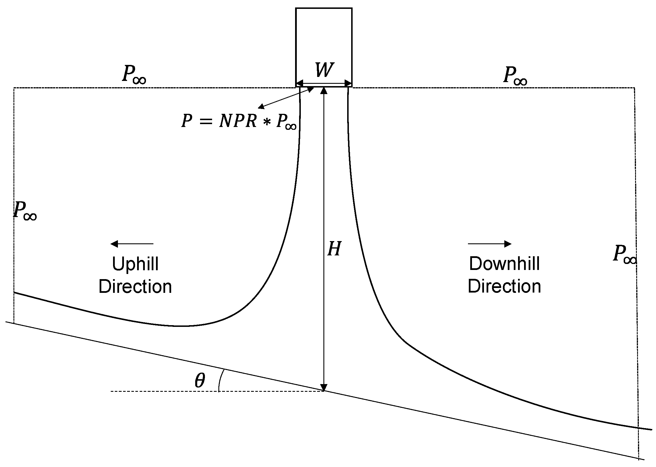
Obliquely impinging under-expanded jets can be characterized by four parameters: the standoff height (H), the jet width (W), the jet nozzle pressure ratio (NPR), and the jet impingement angle (ϴ). The schematic of the jet impingement and the definitions are shown in Figure 1. Table 1 summarizes the range of the values used in this study.
The analysis is performed using non-dimensional parameters, such as the normalized maximum wall shear stress is defined as, where and are the density and velocity at the nozzle exit, respectively. The objective of this work is to develop a set of equations for the prediction of the maximum normalized wall shear stress as a function of the following non-dimensional parameters: jet height to width ratio—, the nozzle pressure ratio— the jet Reynolds number—, and the jet impingement angle—, a naught subscript describes the properties at the nozzle exit.
2.2. Computational Method
The scientific literature does not report the experimental data or DNS related to the wall jet developed from compressible impinging jets. To compute the flow properties needed for the estimation of shear stresses, the CFD simulations solve the steady-state Favre-Averaged Navier–Stokes equations:
Numerical simulations were performed using ANSYS FLUENT 17.2 software (Ansys, Canonsburg, PA, USA). A second-order scheme was used to solve the pressure. A third-order monotonic upstream-centered scheme was used for density, momentum, and turbulence, which was necessary to avoid the effects of numerical viscosity (associated with the low-order schemes) on the jet dissipation, as well as pressure–strain relationship. Since the flow contains non-negligible changes in temperature, the Sutherland model, based on the kinetic theory of ideal gases and an idealized intermolecular force potential, was used for viscosity calculation.
Turbulence closure models are challenged in modeling complex flow phenomena; however, Jaramillo et al. [37] demonstrated that models result in good agreement with DNS when calculating the mean flow of planar impinging jets. The shear stress transport (SST) model used in this work, uses away from the wall in the free stream and free jet portions of the flow while using near the wall to resolve the boundary layer. As demonstrated by Alvi et al. [38] and discussed by Fillingham et al. [23], the SST model [39] is a good choice for modeling underexpanded impinging jets while resolving the wall jet boundary layer. Shukla and Dewan. [40] also found SST to be superior to other closure models when considering planar impinging jets.
The computational grids contain ~500,000 quadrilateral elements. The grid is constructed so that, along the impingement surface, the first node in the wall-normal direction is located within a = 1 at the maximum shear stress location in every case. This is ensured by evaluating the maximum wall shear stress for the normal impingement case at the maximum NPR for each H/W ratio found in our previous work [24] and calculating the distance from the wall that yields = 1 for this maximum wall shear. The of the mesh is generated via biasing from = 5 at the impingement point to = 50 at the edge of the domain. This grid resolution ensures that the viscous sublayer is resolved for the entire domain. The maximum x-direction spacing gives an element aspect ratio of less than 50:1. Mesh independence was confirmed by a simulation with the highest wall shear stress case and doubled number of elements in each direction, such that the first node was placed at = 0.5 still with a maximum aspect ratio of 50:1. This mesh consisted of approximately 2,000,000 elements; this further mesh refinement did not significantly affect the results, leading to only a 0.12% change in the maximum wall shear stress value.
The inlet boundary condition is defined as the exit of an isentropic nozzle where the flow is choked; thus, the boundary can be described by a total pressure, total temperature and a static pressure where the total pressure is necessarily (for an ideal diatomic gas) 1.893 times the static pressure. The walls are modeled as isothermal, no-slip boundaries. The outlets are defined as atmospheric pressure outlets. The outlets are located at 50 jet hydraulic diameters (100 jet slot widths) from the jet axis, corresponding to a minimum of 1.5 times the impingement height.
2.3. Model Validation
Validation of the CFD result is challenging in the absence of the experimental or DNS data for compressible planar impinging jets needed for direct comparison. We evaluated two flow regions: (i) impinging jet and (ii) wall jet region.
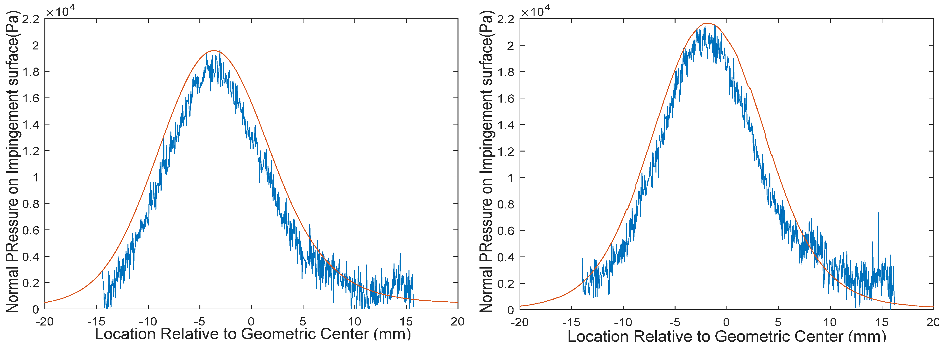
Impinging jet region validation: The implementation of SST jet in the impinging jet region was previously validated with underexpanded axisymmetric jets using Schlieren photography. The shape and the shock structures were shown to be in excellent agreement with experimental observations [23]. Additionally, the CFD simulations were compared with pressure profiles on the impingement surface from pressure-sensitive paint (PSP) experiments [24]. PSP utilizes the emission spectra of a luminophore by relating the emission intensity at specific wavelengths to the partial pressure of oxygen at the surface. Images were taken under wind-on and wind-off conditions, and the images’ intensity ratios were related to pressure. The CFD approach was evaluated using oblique planar jet impingement against the PSP pressure measurements. The oblique jet produces an uphill shift in the impingement point from the geometric center [32]. Figure 2 shows the computed pressure profiles overlayed on the PSP measurements. The CFD simulations show good agreement in the shape and magnitude of the pressure profile.
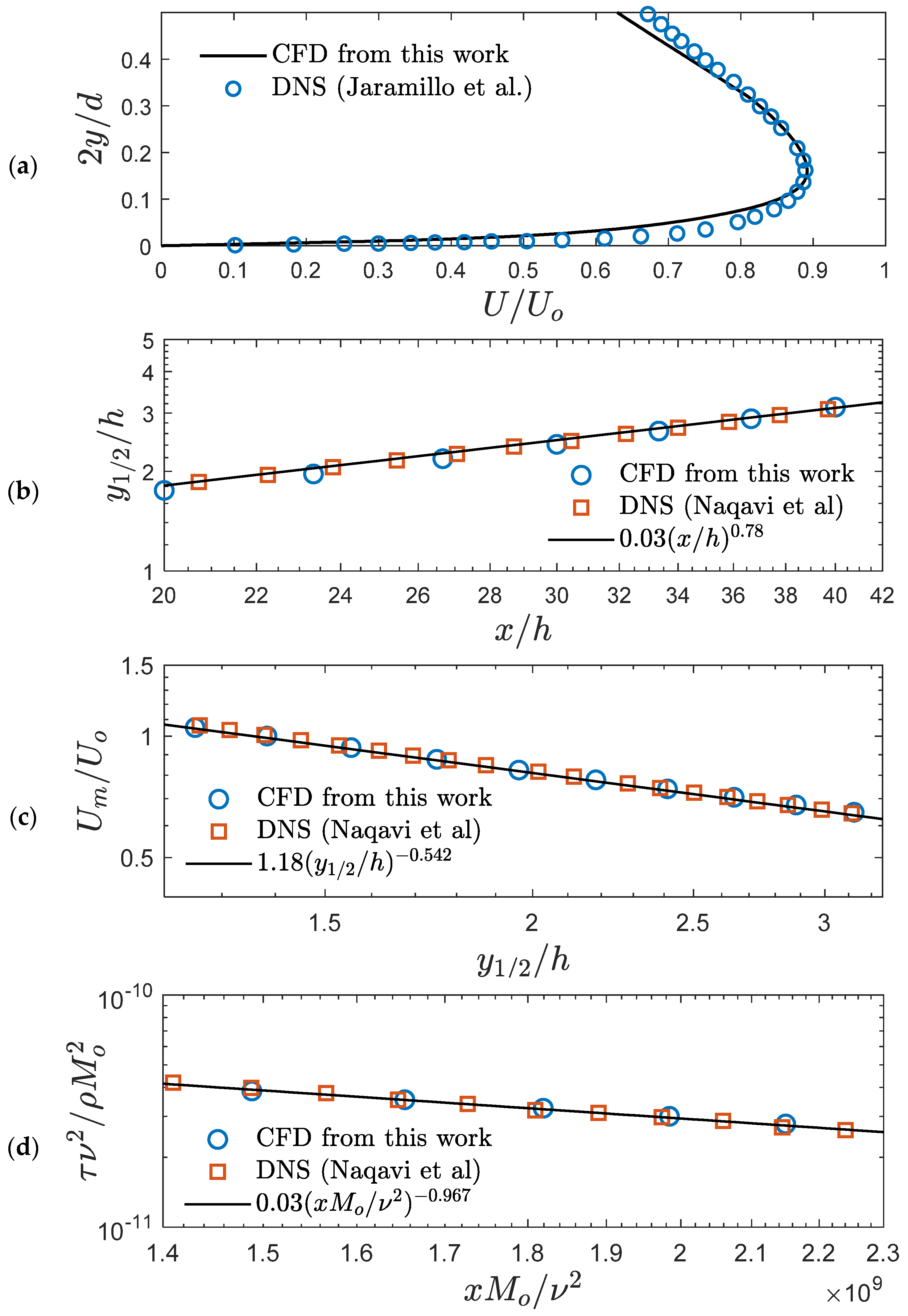
Wall jet region validation: The SST simulations were compared to two separate DNS studies. First, the model was used to replicate DNS data from normal planar impinging jet conducted by Jaramillo et al. [37], reporting wall jet profiles downstream of the impingement point. Figure 3a shows the agreement in velocity profile from Jaramillo et al. and the SST computation. Second, the model was evaluated against the DNS of a classical wall jet conducted by Naqavi et al. [41]. Figure 3b–d compares the development of the wall jet thickness, , the maximum velocity, , and the wall shear stress.
In summary, the SST was found to be an acceptable model for use in the parametric study because of the excellent agreement with the PSP measurements, validation from two DNS studies describing wall jet development, and previously reported Schlieren photography comparison for the axisymmetric impinging jet [23].
3. Results
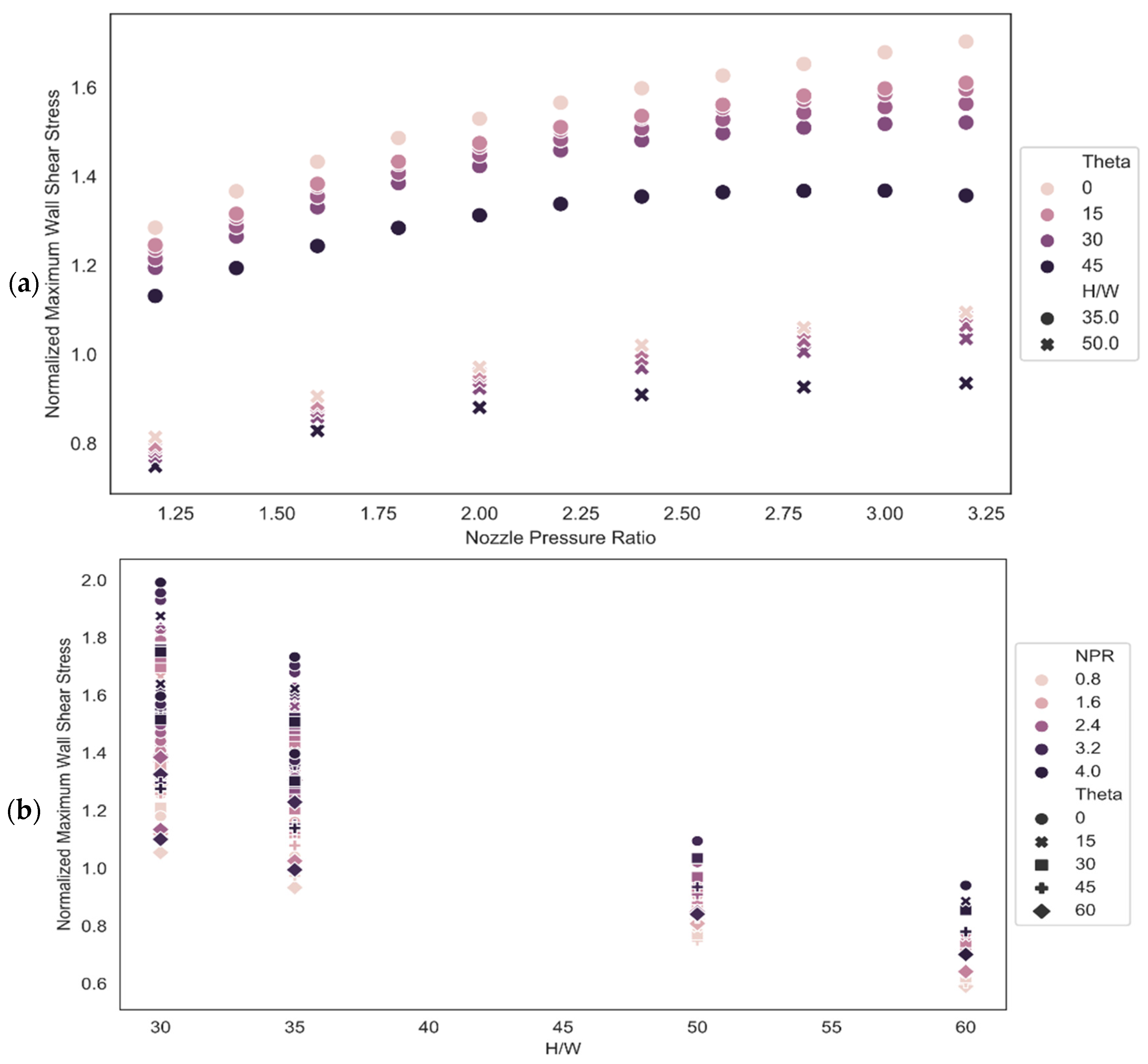
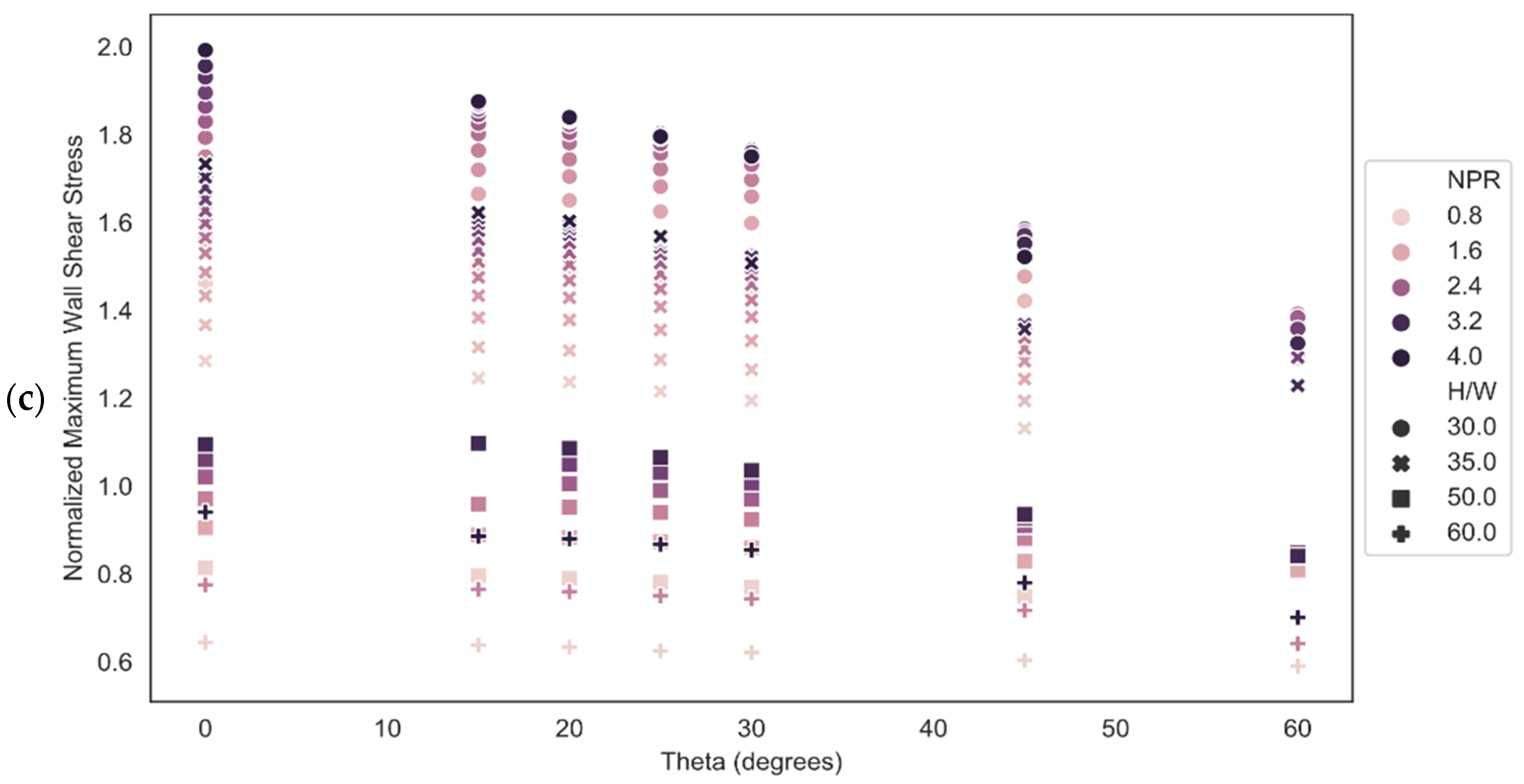
The CFD data for the maximum wall shear stress was tabulated for each case and examined as a function of each jet parameter. As found in our previous work [24], supersonic flow is still present in the boundary layer for H/W values of less than 30. As such, we did not include these cases in the analysis, and the relations developed in this work should only be applied for H/W values above 30. Figure 4a plots the normalized maximum wall shear stress against the nozzle pressure ratio for various conditions. The angle is coded by colors, and the height-to-width ratio is represented by marker type. When each independent parameter is fixed, the maximum wall shear stress increases with approximately the square root of NPR for all cases. Figure 4b plots the normalized maximum wall shear stress against the height to width ratio. As expected, the maximum wall shear stress decreases with increasing height to width ratio. When all other parameters are fixed, the wall shear stress is proportional to the inverse of the height to width ratio. Figure 4c illustrates that maximum wall shear stress decreases with the impingement angle. This relationship was found to resemble a function of the form: . After analyzing the maximum wall shear stress as a function of jet parameters, we propose an equation for normalized maximum wall shear stress of the form
To obtain the global fit based on the form of Equation (1), we first determine the normalized maximum wall shear stress for a normal impingement angle as a function of height to width ratio, nozzle pressure ratio, and jet Reynolds number. Based on our previous work [23], we expect the Reynolds number term to be relevant as it accounts for the effective turbulent viscosity increase for jets with higher Reynolds numbers. This leads to increased energy dissipation in the free jet region and, thus, reduces the maximum wall shear stress after the impingement. Therefore, to describe the maximum wall shear stress at normal impingement, we propose the following equation:
Least-squares fitting gives the following values for the coefficient and exponents:
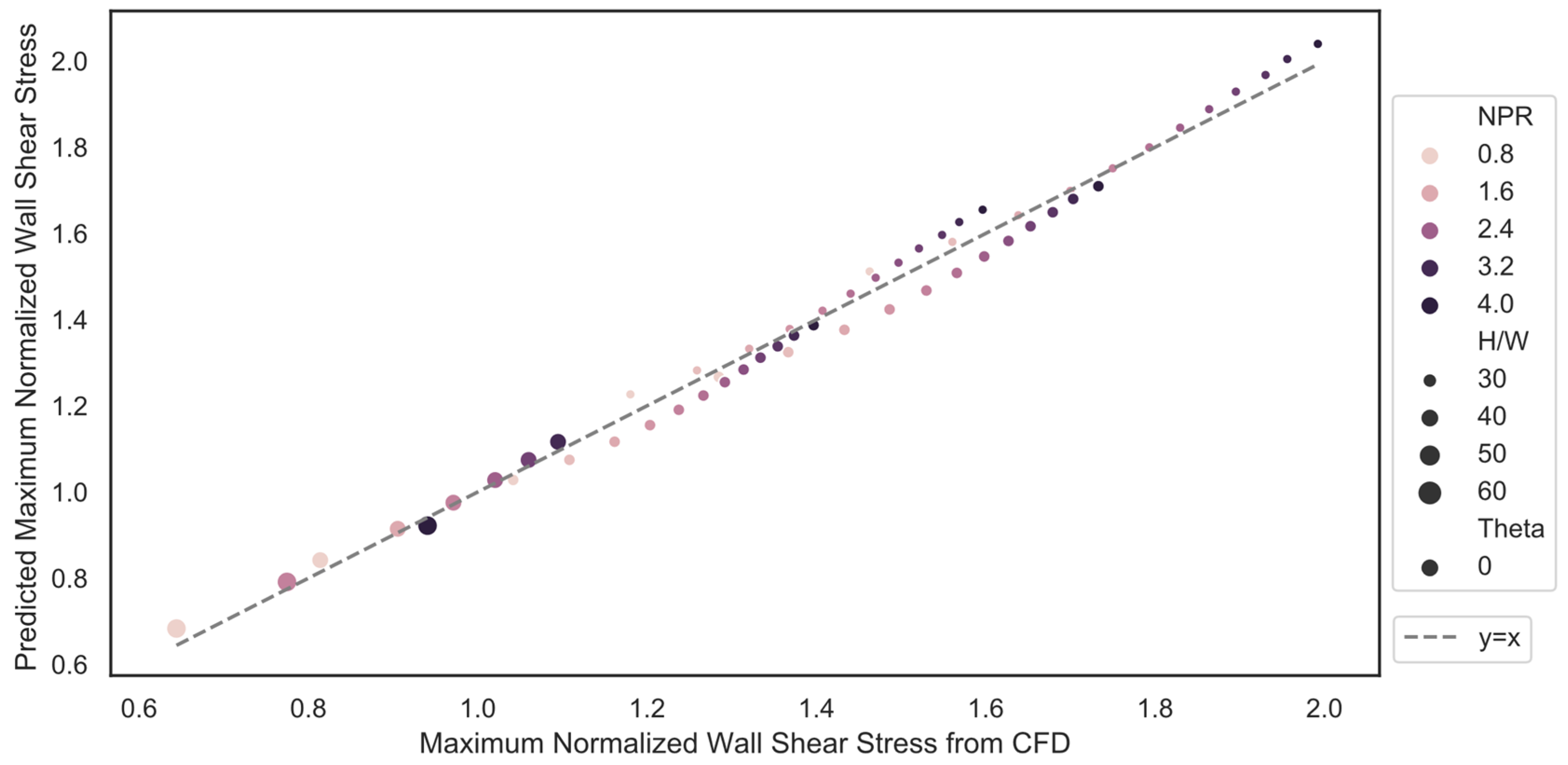
The prediction of maximum wall shear stress from a normal impingement of under-expanded planar jets using Equation (5) agrees with the CFD data with a maximum deviation of 5.7% and a mean deviation of 2.1%. Figure 5 plots the predicted maximum wall shear stress against the calculated value from CFD.
After finding the normal impingement correlations, we calculated the coefficient and exponents for Equation (1). Least-squares fitting yields the following coefficients:
Inserting the coefficients into Equation (4) yields the final expression
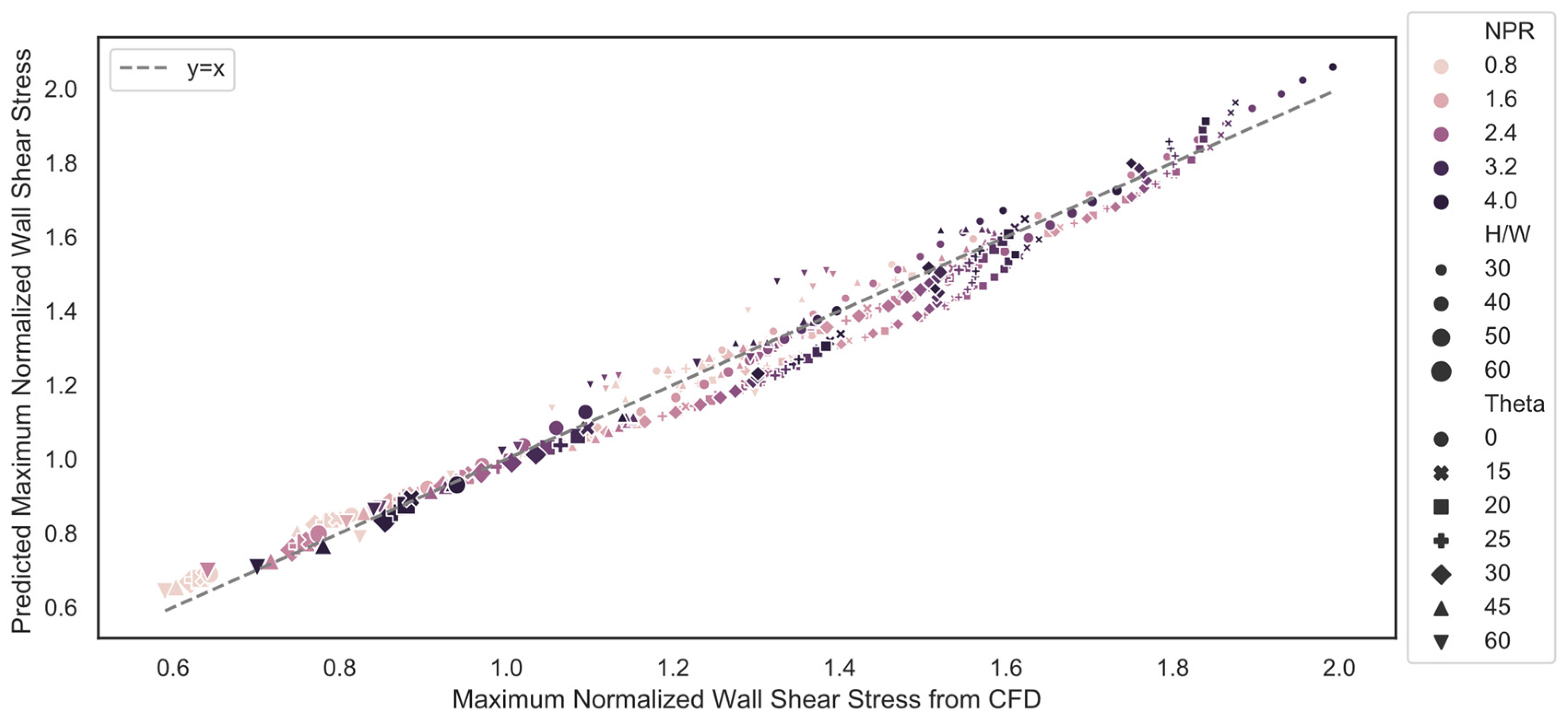
Compared with the numerical data, the predicted normalized maximum wall shear stress has an average deviation of 3.3% and a maximum deviation from CFD of 10.3%. Figure 6 plots the predicted normalized maximum wall shear stress values against the values calculated via CFD.
4. Conclusions
We report empirical formulation for predicting the maximum wall shear stress resulting from obliquely impinging under-expanded planar jets as a function of four jet parameters: the standoff height (H), the jet width (W), the jet nozzle pressure ratio (NPR), and the jet impingement angle (ϴ). The empirical relationship for the normal wall shear stress was developed in the form with the coefficients (). The jet angle correction was implemented in the form with the coefficients () determined based on the least squire fit of the shear stresses calculated using scale resolved CFD simulations. The global expression can predict wall shear stress within a mean error of 3.3%. The formulation can be used to estimate particle resuspension rates and heat transfer rates when correlated with wall shear stresses.
There are limitations to the relationships developed in this work. These expressions will only hold for subsonic boundary layer flow and, as such, should not be extended to use for H/W of less than 30 or NPR above 3.4 without the expectation of error induced due to compressibility. Additionally, the expressions should not be extended to impingement angles above as the characteristics of the system change from an impinging jet to a wall jet, and the expressions will no longer apply.
Author Contributions
Conceptualization, P.F. and I.V.N.; methodology, P.F.; software, P.F. and A.V.; validation P.F.; formal analysis, P.F.; investigation, P.F. and A.V.; resources, I.V.N.; data curation, P.F.; writing—original draft preparation, P.F. and A.V.; writing—review and editing, I.V.N.; visualization, P.F.; supervision, I.V.N.; project administration, I.V.N.; funding acquisition, I.V.N. All authors have read and agreed to the published version of the manuscript.
Funding
This research was funded by DHS Science and Technology Directorate, and UK Home Office; contract no. HSHQDC-15-C-B0033.
Institutional Review Board Statement
Not applicable.
Informed Consent Statement
Not applicable.
Data Availability Statement
The data used in this study will be made available upon reasonable request to the corresponding author.
Acknowledgments
This work was facilitated by using advanced computational, storage, and the networking infrastructure provided by the Hyak supercomputer system at the University of Washington.
Conflicts of Interest
The authors declare no conflict of interests.
References
- Coelho, P.J. Numerical simulation of radiative heat transfer from non-gray gases in three-dimensional enclosures. J. Quant. Spectrosc. Radiat. Transf. 2002, 74, 307–328. [Google Scholar] [CrossRef]
- Hofmann, H.M.; Kind, M.; Martin, H. Measurements on steady state heat transfer and flow structure and new correlations for heat and mass transfer in submerged impinging jets. Int. J. Heat Mass Transf. 2007, 50, 3957–3965. [Google Scholar] [CrossRef]
- Hwang, J.C.; Tsou, F.K.; Cho, W.C. K-EPSILON computations of flow and heat transfer in plane oblique impinging jets. In Computational Methods and Experimental Measurements; Springer: Berlin/Heidelberg, Germany, 1982. [Google Scholar]
- Martin, H. Heat and mass transfer between impinging gas jets and solid surfaces. In Advances in Heat Transfer; Elsevier: Amsterdam, The Netherlands, 1977; Volume 13, pp. 1–60. [Google Scholar]
- Schauer, J. The Flow Development And Heat Transfer Characteristics of Plane Turbulentimpinging Jets; ProQuest Dissertations Publishing: Ann Arbor, MI, USA, 1964. [Google Scholar]
- Kim, D.; Lee, J. Influence of shock structure on heat transfer characteristics in supersonic under-expanded impinging jets. Int. J. Therm. Sci. 2019, 141, 62–71. [Google Scholar] [CrossRef]
- Kim, W.-J.; Karuppuchamy, V.; Heldman, D.R. Evaluation of maximum wall shear stress from air impingement to remove food deposits from stainless steel surfaces. J. Food Eng. 2021, 316, 110825. [Google Scholar] [CrossRef]
- Maithani, R.; Sharma, S.; Kumar, A. Thermo-hydraulic and exergy analysis of inclined impinging jets on absorber plate of solar air heater. Renew. Energy 2021, 179, 84–95. [Google Scholar] [CrossRef]
- Kottapalli, K.; Novosselov, I.V. Aerodynamic resuspension and contact removal of energetic particles from smooth, rough, and fibrous surfaces. Talanta 2021, 231, 122356. [Google Scholar] [CrossRef]
- Novosselov, I.; SpecTree. Pulsed Jet Sampling of Particles and Vapors from Substrates. U.S. Patent 10274404, 30 April 2019. [Google Scholar]
- Novosselov, I.V.; Ariessohn, P.C.; Dengler, E.D.; Hickner, M.; Inventors; Enertechnix, Assignee. Particle Interrogation Devices and Methods. U.S. Patent 8561486, 22 October 2013. [Google Scholar]
- Fillingham, P.; Kottapalli, K.; Zhan, X.; Novosselov, I.V. Characterization of adhesion force in aerodynamic particle resuspension. J. Aerosol Sci. 2019, 128, 89–98. [Google Scholar] [CrossRef]
- Phares, D.J.; Smedley, G.T.; Flagan, R.C. The wall shear stress produced by the normal impingement of a jet on a flat surface. J. Fluid Mech. 2000, 418, 351–375. [Google Scholar] [CrossRef] [Green Version]
- Keedy, R.; Dengler, E.; Ariessohn, P.; Novosselov, I.; Aliseda, A. Removal rates of explosive particles from a surface by impingement of a gas jet. Aerosol Sci. Technol. 2012, 46, 148–155. [Google Scholar] [CrossRef] [Green Version]
- Kottapalli, K.; Novosselov, I.V. Experimental study of aerodynamic resuspension of RDX residue. Aerosol Sci. Technol. 2019, 53, 549–561. [Google Scholar] [CrossRef]
- Fillingham, P.; Vaddi, R.S.; Bruning, A.; Israel, G.; Novosselov, I.V. Drag, lift, and torque on a prolate spheroid resting on a smooth surface in a linear shear flow. Powder Technol. 2021, 377, 958–965. [Google Scholar] [CrossRef]
- Mercier-Bonin, M.; Dehouche, A.; Morchain, J.; Schmitz, P. Orientation and detachment dynamics of Bacillus spores from stainless steel under controlled shear flow: Modelling of the adhesion force. Int. J. Food Microbiol. 2011, 146, 182–191. [Google Scholar] [CrossRef]
- Kesavan, J.S.; Humphreys, P.D.; Bottiger, J.R.; Valdes, E.R.; Rastogi, V.K.; Knox, C.K. Deposition method, relative humidity, and surface property effects of bacterial spore reaerosolization via pulsed air jet. Aerosol Sci. Technol. 2017, 51, 1027–1034. [Google Scholar] [CrossRef] [Green Version]
- Henry, C.; Minier, J.-P. Progress in particle resuspension from rough surfaces by turbulent flows. Prog. Energy Combust. Sci. 2014, 45, 1–53. [Google Scholar] [CrossRef]
- Kalghatgi, G.; Hunt, B. The occurrence of stagnation bubbles in supersonic jet impingement flows. Aeronaut. Q. 1976, 27, 169–185. [Google Scholar] [CrossRef]
- Henderson, B.; Powell, A. Experiments concerning tones produced by an axisymmetric choked jet impinging on flat plates. J. Sound Vib. 1993, 168, 307–326. [Google Scholar] [CrossRef]
- Krothapalli, A.; Rajkuperan, E.; Alvi, F.; Lourenco, L. Flow field and noise characteristics of a supersonic impinging jet. J. Fluid Mech. 1999, 392, 155–181. [Google Scholar] [CrossRef]
- Fillingham, P.; Murali, H.; Novosselov, I.V. Nondimensional Parameter for Characterization of Wall Shear Stress From Underexpanded Axisymmetric Impinging Jets. J. Fluids Eng. 2017, 139, 111102. [Google Scholar] [CrossRef]
- Fillingham, P.; Novosselov, I.V. Wall jet similarity of impinging planar underexpanded jets. Int. J. Heat Fluid Flow 2020, 81, 108516. [Google Scholar] [CrossRef]
- Roy, S.; Patel, P. Study of heat transfer for a pair of rectangular jets impinging on an inclined surface. Int. J. Heat Mass Transf. 2003, 46, 411–425. [Google Scholar] [CrossRef]
- Attalla, M.; Maghrabie, H.M.; Specht, E. Effect of inclination angle of a pair of air jets on heat transfer into the flat surface. Exp. Therm. Fluid Sci. 2017, 85, 85–94. [Google Scholar] [CrossRef]
- Zhang, M.; Wang, N.; Han, J.-C. Internal heat transfer of film-cooled leading edge model with normal and tangential impinging jets. Int. J. Heat Mass Transf. 2019, 139, 193–204. [Google Scholar] [CrossRef]
- Miguel-González, C.; García-Díaz, M.; Pereiras, B.; Vigil, M.; Rodríguez de Castro, A. Numerical model of a planar jet wiping system for continuous strip lines. J. Mech. Sci. Technol. 2021, 35, 2929–2938. [Google Scholar] [CrossRef]
- Crafton, J.; Carter, C.; Elliott, G.; Sullivan, J. The impingement of sonic and sub-sonic jets onto a flat plate at inclined angles. Exp. Methods Appl. Fluid Flow 2006, 41, 699–710. [Google Scholar] [CrossRef]
- Nguyen, T.; Blake, M. Flowfield Characteristics of a Supersonic Jet Impinging on an Inclined Surface. Am. Inst. Aeronaut. Astronaut. AIAA J. 2020, 58, 1240–1254. [Google Scholar] [CrossRef]
- Dorrepaal, J.M. An exact solution of the Navier-Stokes equation which describes non-orthogonal stagnation-point flow in two dimensions. J. Fluid Mech. 1986, 163, 141–147. [Google Scholar] [CrossRef]
- Beltaos, S. Oblique impingement of plane turbulent jets. J. Hydraul. Div. 1976, 102, 1177–1192. [Google Scholar] [CrossRef]
- Chin, D.; Agarwal, M. Mass-Transfer from an Oblique Impinging Slot Jet. J. Electrochem. Soc. 1991, 138, 2643–2650. [Google Scholar] [CrossRef]
- Mazurek, K.A.; Rajaratnam, N. Erosion of sand beds by obliquely impinging plane turbulent air jets. J. Hydraul. Res. 2005, 43, 567–573. [Google Scholar] [CrossRef]
- Kesavan, J.; Humphreys, P.; Nasr, B.; Ahmadi, G.; Knox, C.K.; Valdes, E.; Rastogi, V.; Dhaniyala, S. Experimental and computational study of reaerosolization of 1 to 5 μm PSL microspheres using jet impingement. Aerosol Sci. Technol. 2017, 51, 377–387. [Google Scholar] [CrossRef]
- Nasr, B.; Ahmadi, G.; Ferro, A.R.; Dhaniyala, S. A model for particle removal from surfaces with large-scale roughness in turbulent flows. Aerosol Sci. Technol. 2020, 54, 291–303. [Google Scholar] [CrossRef]
- Jaramillo, J.; Trias, F.; Gorobets, A.; Pérez-Segarra, C.; Oliva, A. DNS and RANS modelling of a turbulent plane impinging jet. Int. J. Heat Mass Transf. 2012, 55, 789–801. [Google Scholar] [CrossRef]
- Alvi, F.; Ladd, J.; Bower, W. Experimental and computational investigation of supersonic impinging jets. Am. Inst. Aeronaut. Astronaut. AIAA J. 2002, 40, 599–609. [Google Scholar] [CrossRef]
- Menter, F. (Ed.) Zonal two equation kw turbulence models for aerodynamic flows. In Proceedings of the 23rd Fluid Dynamics, Plasmadynamics, and Lasers Conference, Orlando, FL, USA, 6–9 July 1993. [Google Scholar]
- Shukla, A.K.; Dewan, A. Flow and thermal characteristics of jet impingement: Comprehensive review. Int. J. Heat Technol. 2017, 35, 153–166. [Google Scholar] [CrossRef] [Green Version]
- Naqavi, I.Z.; Tyacke, J.C.; Tucker, P.G. Direct numerical simulation of a wall jet: Flow physics. J. Fluid Mech. 2018, 852, 507–542. [Google Scholar] [CrossRef] [Green Version]
Figure 1.
Schematic of oblique jet impingement on a flat plate.

Figure 2.
Normal pressure profiles from CFD (red) and pressure-sensitive paint (blue) experiments for h = 30 mm, d = 1 mm, NPR = 1.0 with the impingement angle of 30 degrees (left) and 15 degrees (right), as shown originally in Fillingham et al. [24].
Figure 2.
Normal pressure profiles from CFD (red) and pressure-sensitive paint (blue) experiments for h = 30 mm, d = 1 mm, NPR = 1.0 with the impingement angle of 30 degrees (left) and 15 degrees (right), as shown originally in Fillingham et al. [24].

Figure 3.
Validation of SST for impinging jet modeling as shown originally in Fillingham et al. [24]. (a) Comparison of the velocity profile at 8 jet widths downstream of impingement location against DNS from Jaramillo et al. [37]. Comparison with wall jet DNS simulation from Naqavi et al. [41] (b) Decay of half maximum velocity location. (c) Maximum velocity. (d) Wall shear stress.

Figure 4.
Normalized maximum wall shear stress plotted against Nozzle parameters with impingement angle represented by shade and height to width ratio designated by the symbol (a) nozzle pressure ratio, (b) height-to-width ratio, (c) impingement angle.
Figure 4.
Normalized maximum wall shear stress plotted against Nozzle parameters with impingement angle represented by shade and height to width ratio designated by the symbol (a) nozzle pressure ratio, (b) height-to-width ratio, (c) impingement angle.


Figure 5.
Predicted maximum normalized wall shear stress plotted against maximum normalized wall shear stress from CFD for normal impingement. Shade represents the nozzle pressure ratio, whereas the symbol represents the height-to-width ratio.
Figure 5.
Predicted maximum normalized wall shear stress plotted against maximum normalized wall shear stress from CFD for normal impingement. Shade represents the nozzle pressure ratio, whereas the symbol represents the height-to-width ratio.

Figure 6.
Predicted maximum normalized wall shear stress plotted against maximum normalized wall shear stress from CFD for all impingement angles. Shade represents the nozzle pressure ratio, the symbol represents the impingement angle, and the marker size represents the height-to-width ratio.
Figure 6.
Predicted maximum normalized wall shear stress plotted against maximum normalized wall shear stress from CFD for all impingement angles. Shade represents the nozzle pressure ratio, the symbol represents the impingement angle, and the marker size represents the height-to-width ratio.


Table 1.
Range of geometric conditions used in the study.
| Standoff Distance, H (mm) | 15.0, 17.5, 30.0, 35.0, 60.0, 100.0 |
| Width of the nozzle, W (mm) | 0.5, 1.0, 2.0 |
| Jet Angle, (°) | 0, 15, 20, 30, 45, 60 |
| Nozzle exit pressure ratio, NPR | 1.0, 1.2, 1.4, 1.6, 1.8, 2.0, 2.2, 2.4, 2.6, 2.8, 3.0, 3.2, 3.4 |
Publisher’s Note: MDPI stays neutral with regard to jurisdictional claims in published maps and institutional affiliations. |
© 2022 by the authors. Licensee MDPI, Basel, Switzerland. This article is an open access article distributed under the terms and conditions of the Creative Commons Attribution (CC BY) license (https://creativecommons.org/licenses/by/4.0/).
Share and Cite
MDPI and ACS Style
Fillingham, P.; Viswanathan, A.; Novosselov, I.V. Model for Wall Shear Stress from Obliquely Impinging Planar Underexpanded Jets. Appl. Sci. 2022, 12, 7311. https://0-doi-org.brum.beds.ac.uk/10.3390/app12147311
AMA Style
Fillingham P, Viswanathan A, Novosselov IV. Model for Wall Shear Stress from Obliquely Impinging Planar Underexpanded Jets. Applied Sciences. 2022; 12(14):7311. https://0-doi-org.brum.beds.ac.uk/10.3390/app12147311
Chicago/Turabian StyleFillingham, Patrick, Arjun Viswanathan, and Igor V. Novosselov. 2022. "Model for Wall Shear Stress from Obliquely Impinging Planar Underexpanded Jets" Applied Sciences 12, no. 14: 7311. https://0-doi-org.brum.beds.ac.uk/10.3390/app12147311
Note that from the first issue of 2016, this journal uses article numbers instead of page numbers. See further details here.