
Design of Test Equipment for Hydrostatic Transducers and Hydraulic Fluids


Institute of Agricultural Engineering, Transport and Bioenergetics, Faculty of Engineering, Slovak University of Agriculture in Nitra, Tr. A. Hlinku 2, 949 76 Nitra, Slovakia
*
Author to whom correspondence should be addressed.
Appl. Sci. 2022, 12(15), 7777; https://0-doi-org.brum.beds.ac.uk/10.3390/app12157777
Submission received: 4 July 2022
/
Revised: 29 July 2022
/
Accepted: 29 July 2022
/
Published: 2 August 2022
(This article belongs to the Special Issue Advanced Engine Technologies and Innovative Vehicle Driving Systems)
Abstract
:The article refers to the proposed test equipment used to monitor the service life of hydrostatic transducers and fluids under constant or dynamic operating pressure loading. The proposed laboratory test equipment enables simultaneous testing of hydrostatic transducers and energy carriers in two hydraulic circuits and is designed to measure the flow characteristics and technical life of hydrostatic transducers with different energy carriers. The benefit of the proposed device is the possibility of simultaneous testing of the transducers as well as the performance of verification measurements of individual circuits, which was preceded by the development of a theoretical design. This includes the calculations necessary to determine the power of the drive, the cooling power as well as the definition of other parameters and elements of the hydraulic system. The design of the device was based on technical characteristics, load characteristics obtained by own measurements, and characteristics of individual hydraulic and electrohydraulic elements. On the basis of the prepared laboratory test equipment, it is possible to significantly shorten the time of operational tests and perform repeated tests under the same operational load with different types of energy carriers. The hydraulic circuit (primary or secondary) can be loaded through a proportional electrohydraulic pressure valve, which is able to simulate the load with the operational pressure curve obtained by measurement, as well as the cyclic stress, the frequency, amplitude, and rate of increase of which can be defined according to the selected methodology. A verification measurement of the flow characteristics of the used transducers was also carried out, which confirmed the correct function and design of the test laboratory equipment. The achieved results can be used in mechanical engineering for the accelerated life test of hydrostatic transducers, which are often used in mobile energy devices working in environmentally sensitive areas. The proposed laboratory test equipment will be used for testing ecological energy carriers, increasing the efficiency of energy conversion in agricultural facilities using biomass.
1. Introduction
The mechanization of agriculture is related to the constant increase in the mobile energy means technical level. These are increasingly influenced by modern forms of agricultural production. Increasingly, there are growing demands on the performance of machines, which need to consider their impact and negative impacts on the environment [1].
One of the most frequently used mobile energy means in agriculture is an agricultural tractor, which by its construction is adapted so that its specific operating properties are effectively used [2]. When the fluid flows through, for example, a narrowed flow cross-section, the pressure can drop below the atmospheric pressure value, to the value of the fluid’s saturated vapors, resulting in evaporation. Cavities are formed, which are filled with fluid vapors. The collapse of cavities is often implosive, which causes noise and shocks. As a result of impacts, the surface is broken at the point of contact with the wrapped material [3]. The energy transmission of agricultural machinery, as well as other mobile energy means used in the agricultural industry, is ensured by means of hydraulic fluids. However, their leakage causes pollution of soil and water sources, which are, as a result of this leakage, unsuitable for further use for a long time. Fluid leakage, which occurs during normal operation of the machines in the given conditions, is considered a fault, which in practice cannot be eliminated. For this reason, it is necessary to propose improvements in technical solutions, or the type of fluids that will not endanger the environment or its components [4]. In this mechanization, hydrostatic transducers are used. According to [5], the term hydrostatic transducers refer to hydraulic elements that transfer energy from solid parts to a column of fluid and vice versa. The input energy source can be an electric motor or an internal combustion engine. The hydrogenerator creates pressure energy of the fluid and, through control elements and auxiliary elements, transfers it to the hydromotor, where the pressure energy of the fluid is converted into mechanical energy [6]. In order to ensure the transfer of energy through the hydraulic fluid (energy carrier) in the hydraulic system, it is necessary to have a suitable arrangement of interconnected elements [7]. Authors [8] used a mechanical proportional pressure valve in the construction of a hydraulic load device to simulate the load gear hydraulic pump with external gearing. In their work, they observed an increase in the flow of the hydraulic pump depending on a continuous change in speed rotation, while the increase in flow was continuous. Authors [9] in their work present a simulation of the resulting flow of a gear hydraulic pump with a change in the size of the flow depending on the speed rotation of the hydraulic pump.
In this work we deal with the design of test equipment, the influence of fluids on the transmission and hydraulic system of mobile equipment, their suitability for use in hydrostatic systems of transport and handling equipment, and various types of tests that are energy and time consuming. For these reasons, accelerated life tests of hydraulic elements and fluids are used, where we simulate the operating load in laboratory conditions and after the test the physico-chemical properties are analyzed, and the influence of the used fluid on the technical condition of the selected machine element, which is most sensitive to operating fluid properties. The article describes the design of laboratory equipment for measuring the qualitative properties of energy carriers and transducers by simulating operational loads. The aim of the contribution is the design and verification of laboratory equipment, which is used in the research of the degradation of new types of energy carriers and their influence on the flow characteristics of the used transducer. The laboratory equipment is primarily intended for the evaluation of new ecological fluids, which are used as an energy carrier in machines working in ecologically sensitive areas, where their leakage could, for example, cause soil and groundwater pollution. The influence of ecological fluids, in terms of their composition, on individual parts of the hydraulic circuit and seals has not been fully investigated. For this reason, it is necessary to carry out laboratory tests before the introduction of new fluids, which reduce the risk of damage to the machine, shorten the test, and lower financial demands. In recent years, modern trends in agriculture have focused on innovative technological procedures for the use of biomass in agriculture. Our aim was to design a test laboratory equipment that will enable the testing of ecological energy carriers, the basic components of which are grown as biomass on degraded and food-unused land.
2. Materials and Methods
The design of test equipment for hydrostatic transducers of transmission systems of hydraulic circuits and hydraulic fluids is used to monitor the life of hydrostatic transducers under static and dynamic loading in laboratory conditions of operating pressure and temperature, with the possibility of simultaneous testing of two working fluids and repeated simulation of operating conditions. When designing the loading equipment, we used the technical characteristics, the load characteristics obtained by self-measurement, the characteristics determined by the manufacturer of individual hydraulic and electro-hydraulic elements and the calculations performed. The service life of the tractor′s hydraulic pumps will be assessed in terms of the change in flow characteristic Q depending on the hours worked with different types of hydraulic fluid in the primary and secondary circuit. The hydraulic pump is driven by an electric motor, the required input speed of the hydraulic pump drive shaft is controlled by a frequency converter and the hydraulic pump is directly connected to the electric motor. The proposed laboratory test equipment will be designed to measure the flow characteristics of hydrostatic transducers, which can be measured on the proposed equipment:
- Q = f(p)n dependence of flow on pressure at constant speed rotation;
- Q = f(n)p dependence of flow on speed at constant pressure.
where:
p—pressure at constant speed rotation, MPa
n—rotation speed of transducer, rpm
2.1. Methodology of Design of Test Equipment for Hydrostatic Transducers
The design of a laboratory test device for hydrostatic transducers and hydraulic fluids with the possibility of simulating the operating modes of the agricultural tractor was based on the need to determine the effect of new types of fluids (biodegradable) on the technical condition of the transducers and individual parts of the hydraulic circuit, or to perform a simultaneous comparison of two fluids or transducers before their introduction into operation and at the same time reduce the costs of tests. In the proposed laboratory test facility, it is in the primary and secondary hydraulic circuits connected system of the following hydraulic elements:
- (a)
- gear hydrogenerator,
- (b)
- gear hydraulic motor,
- (c)
- safety pressure valve,
- (d)
- shut-off valve,
- (e)
- throttle valve with stabilization,
- (f)
- electro-hydraulic proportional valve,
- (g)
- switchboard,
- (h)
- three-way valve,
- (i)
- filter,
- (j)
- cooler,
- (k)
- reservoir.
When designing hydraulic circuits, it is necessary to adhere to principles that ensure a corresponding rational solution:
- Determining the exact requirements placed on the system—what activity should the hydrostatic transducers perform, under what conditions and required parameters (forces, moments, revolutions, ambient temperature, working environment, service quality, etc.).
- Before starting work on the project, it is necessary to have sufficient technical information about the elements of the hydraulic circuit that will be connected in the test facility. The elements in the circuit should be optimally used, but not overloaded.
- When designing the hydraulic circuit, we start from the optimal system of hydraulic elements for the given requirements and the simplest possible control. The entire hydraulic circuit must be checked by calculating the load forces, moments, and work pressure. Furthermore, it is necessary to check the speed of movement of hydraulic elements and currents, pressure losses, efficiency, power input and output, heat balance, and tank size.
- We mark the elements in the functional diagram with symbols according to DIN ISO 1219 (this avoids errors in connection).
- The design of the laboratory test equipment project also includes the calculation of the required power and revolutions during dynamic loading of the transducers, the appropriate choice of frequency converter, tank volume, hydraulic fluid cooling system, and determination of line clearance.
- We use the working fluid only as recommended by the manufacturer of the hydraulic circuit elements.
- During the verification measurement of the hydraulic circuit, we follow the instructions and requirements of the manufacturer of hydraulic elements.
- During the test run, we constantly monitor the oil temperature, the state of the oil level in the tank, and the function and tightness of the entire circuit.
2.1.1. Characteristics of the Measured Object for Verification Measurement
In the proposed test equipment, gear hydrostatic transducers with a geometric volume of 17.39 cm3 are used. Parameters of those devices are given in Table 1, Table 2 and Table 3. The mentioned device allows the use of transducers with a geometric volume of up to 82 cm3 and a working pressure of up to 30 MPa.
The hydrogenerator GHD1-17R-S2D1 is a high-pressure device, manufactured in twelve consecutive series (X, P23, J, T3, T3S, UD, Q2, QHD1, QHD2, GHD0, GHD1 GHD2) with a geometric volume ranging from 0, 18 to 150 cm3. The entire range of hydrogenerators in the P23, J, T3, UD, and Q2 series is also offered in a reverse version as hydromotors, which can be equipped with a special shaft seal with a pressure resistance of up to 1 MPa.
2.1.2. Theoretical Assumptions for Leading Hydrostatic Transducers with Constant and Operating Pressure
Based on the obtained time courses of operating pressures in the tractor’s hydraulic system, a control program was designed to simulate the dynamic loading of hydraulic system elements and hydraulic fluids, constant pressure loading, and elevated temperature loading in laboratory conditions. The required simulated course of hydrostatic transducers loading is realized by changing the pressure drop on hydraulic pumps. The required change of the dynamic load of the hydraulic pump will be controlled via a proportional pressure valve, which after connection in the primary circuit during the hydraulic pump test will ensure a continuous conversion of the control signal to the required pressure of the working fluid.
In this case, the accelerated life test of hydrostatic transducers in order to verify the technical life of the transducer under its cyclic loading was according to the prescribed cycle in standard ČSN 11 9287 (ST SEV 2576-80) when determining the requirements for test equipment, we based on the parameters of tested transducers, which set out as follows: “Technical life at cyclic compressive stress from zero to nominal pressure with a frequency of 0.5 to 1.25 Hz, at a pressure flow rate of 10 to 35 MPa·s−1, at nominal parameters must be at least 106 cycles, Figure 1 shows the theoretical course of the loading cycle. A reduction in flow efficiency of a maximum of 20% is permitted. Cyclic compressive stress in the primary hydraulic circuit is provided by an electro-hydraulically controlled switchboard, which is connected to the output of the hydraulic pump. Changing the position of the manifold results in a change in the direction of the fluid flow, thus changing the load pressure conditions at the outlet of the hydraulic pump [10,11,12,13,14,15].
Using the proportional valve, it is possible to set various load parameters according to Vickers, ASTDM, or ISO standards or parameters measured in operation.
The principle of operation of the laboratory test equipment during in-service tests consists in simulating pressures through a proportional pressure valve, which is connected in the primary or secondary circuit as required, thus creating a load on individual hydraulic circuit elements and at the same time operating fluid test. The basic building block of the laboratory test equipment for simulating the operating pressure load is an electro-hydraulic proportional valve, the proportional control of which modulates the hydraulic parameters in accordance with the electrical reference signals. Electro-hydraulic control systems are part of the entire automation architecture of the laboratory test equipment, together with the created control program. The proportional valve can be equipped with a safety operation. It means that if there is no reference signal, or in general, when a mains failure occurs, no damage will occur to the test system.
2.2. Monitoring of Selected Parameters
For the measurement of the selected parameters necessary for the evaluation of the influence of the fluid and the technical condition of the transducers, the measurement technique must be chosen with regard to the range and accuracy.
2.2.1. Monitoring of Pressure, Flow and Temperature
Author [10] deals with the design of laboratory test equipment for testing hydraulic circuit elements and hydraulic fluids in his scientific monograph. The measuring technology, which is part of the hydraulic circuit, consists of a Hydac ETS 4144-A000 temperature sensor, a Hydac EVS 3110-1 flow sensor, and a Hydac HDA 3744-A-400-000 pressure sensor, which are connected to the HMG 3010 recording unit. Thanks to this, it is possible to simultaneously measure and record all three quantities. The recording unit allows the measurement of the flow in the range of 6–60 dm3 min−1, 15–300 dm3 min−1, and 40–600 dm3 min−1, the pressure in the range of 40 MPa, and the temperature to 100 °C (Figure 2).
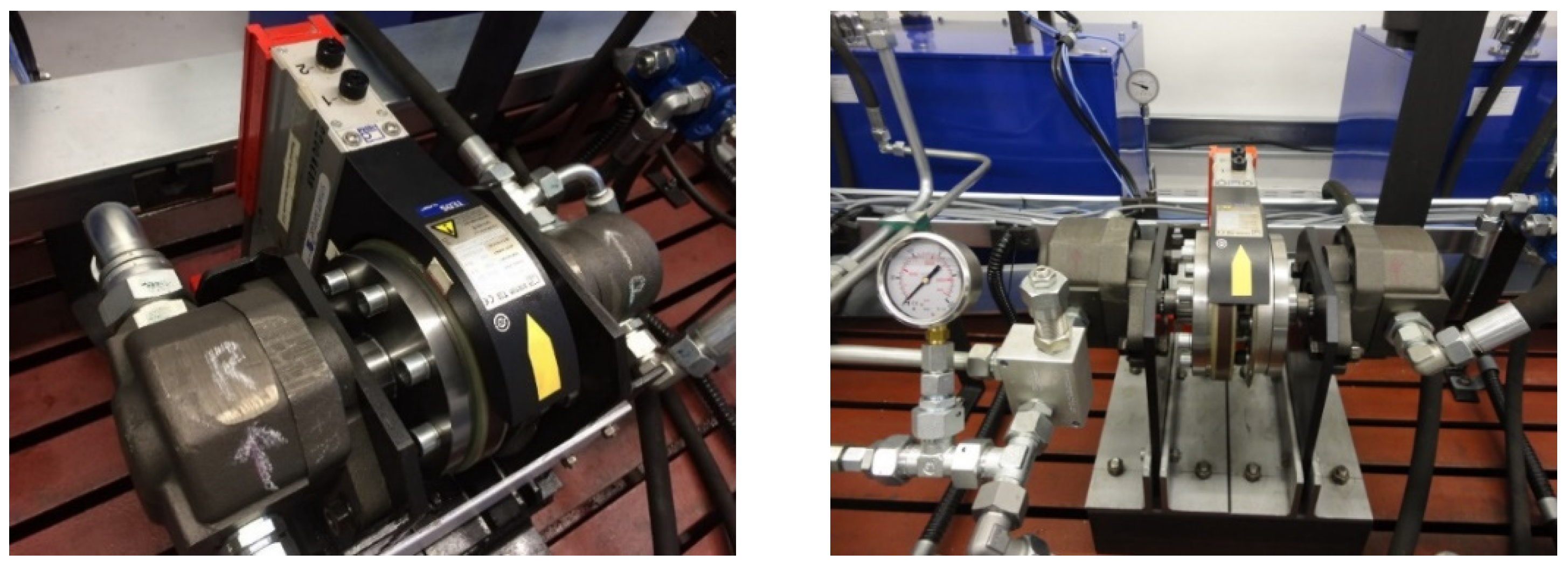
2.2.2. Monitoring of Torque and Speed Rotation
The combined torque and speed rotation sensor (Figure 3) has found application in the proposed laboratory test equipment and reads the parameters of the rotary hydraulic motor in the speed rotation range of 0 to 12,000 rpm. The nominal value of the torque on the output shaft of the hydraulic pump included in the primary hydraulic circuit is 2000 Nm. It is also possible to calculate the transmitted power from the obtained measured values.
Parameters of the HBM Stator T12 torque sensor are given in Table 4.
3. Results
3.1. Implementation of the Developed Experimental Device
The design of the laboratory test equipment was based on the need of monitoring hydrostatic transducers and the use of ecological fluids in agricultural and forestry tractors operating in ecologically sensitive areas, while input data from operational tests served as a basis for developing the design of the described equipment. Partial results from operational tests, which were published in scientific journals by the authors [16,17,18,19,20], were used in the analytical solution of the test equipment design.
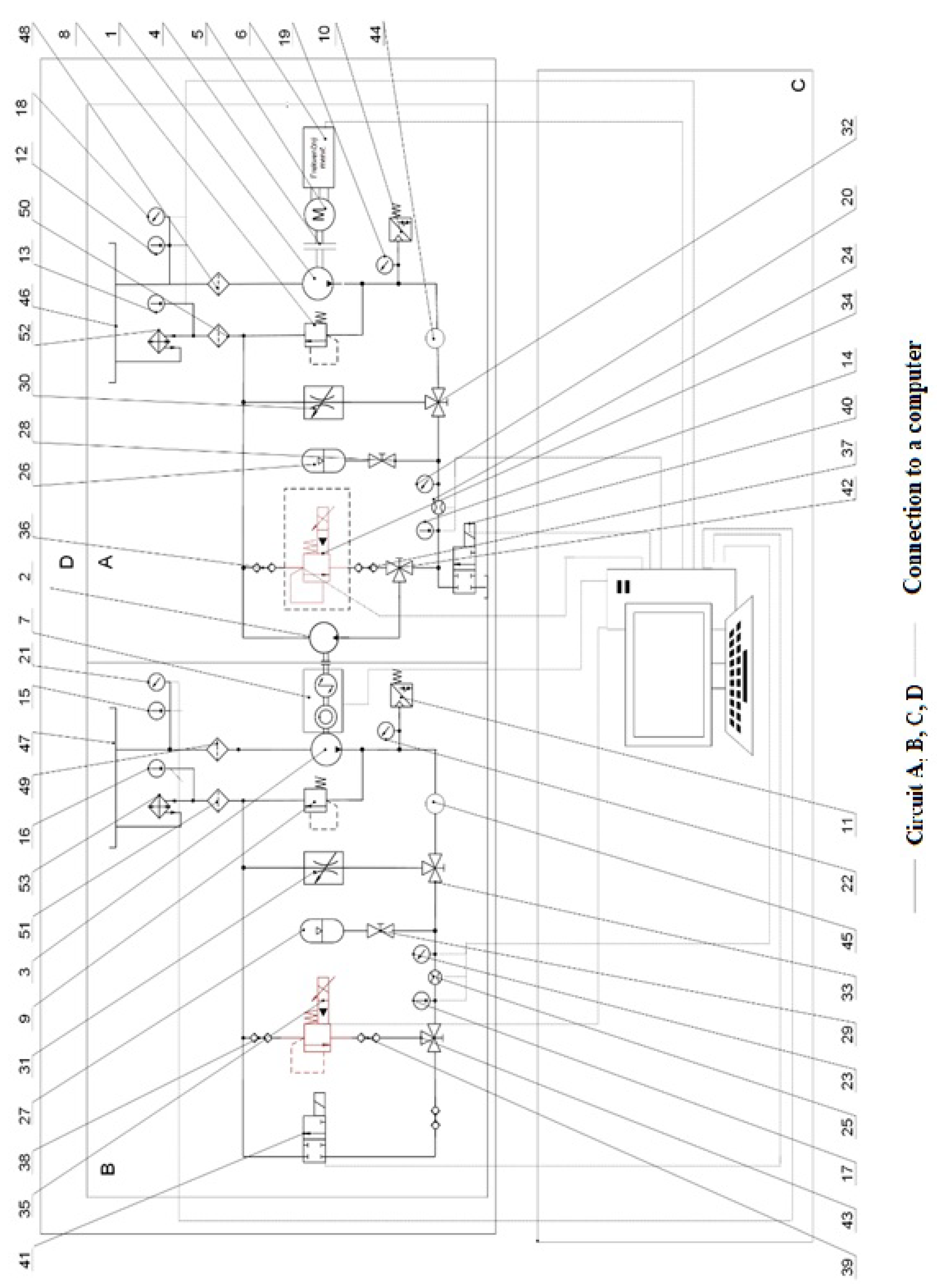
The essence of the technical solution of the proposed test laboratory equipment lies in the fact that the equipment allows based on the selected test to measure the same laboratory equipment flow characteristics of hydraulic pump (1) in the primary (driving) hydraulic circuit (A), flow characteristics of hydraulic pump (3) in the secondary (driven) hydraulic circuit (B), service life of hydraulic pump (1), (3) and hydraulic motor (2) in hydraulic circuits (A) and (B), static and dynamic loading of hydraulic pump (1), (3) and hydraulic motor (2) in hydraulic circuits (A) and (B) and simultaneous testing of physic-chemical properties of different energy carriers in hydraulic circuits (A) and (B). The functional diagram of the laboratory test equipment of hydrostatic transducers and energy carriers in two circuits with an electro-hydraulic proportional valve is shown in Figure 4. The drive of hydrostatic transducers of the laboratory test equipment is provided by an electric motor (5), which is connected to a frequency converter (6) to achieve constant, resp. required speed regardless of the load. The hydraulic circuits (A) and (B) are interconnected by a combined sensor (7), which makes it possible to measure torque and speed. The two hydraulic circuits (A) and (B) can be disconnected from each other, while the possibility of testing the hydraulic pump in the primary circuit remains. The hydraulic circuits (A) and (B) are secured against overload mechanically, by pressure valves (8) and (9) and electrically, by pressure switches (10) and (11). Temperature sensors (12), (13), (14), (15), (16), and (17), pressure sensors (18), (19), (20), (21), (22), and (23), and flow sensors (24) and (25) are equipped in both hydraulic circuits (A) and (B) for sensing operating conditions. To dampen pressure shocks, pressure accumulators (26) and (27) are located in both hydraulic circuits, the actuation of which is ensured by shut-off valves (28) and (29). Throttle valves with stabilization (30) and (31) with control of fluid supply via three-way valves (32) and (33) serve to ensure that the operating temperature is reached or to simulate a higher thermal load of the monitored energy carriers (Figure 4).
In the hydraulic circuits (A) and (B) it is possible to connect electro-hydraulic proportional valves (34) and (35) via quick couplings (36), (37), (38), and (39). Electro-hydraulic proportional valves (34) and (35) are used to simulate the pressure load at life tests. In order to provide different types of tests and the possibility of using the hydraulic circuit (A) separately, a separate electro-hydraulic proportional valve (34), (35) and a separate tank (46), (47) are designed for each hydraulic circuit (A) and (B). The tanks are equipped with inlet filters (48) and (49) and outlet filters (50) and (51). Coolers (52) and (53) with an electric fan are used to maintain the required operating temperature in the hydraulic circuits (A) and (B). The electro-hydraulic distributor (41) included in the hydraulic circuit (B) serves for cyclic loading of the hydraulic motor (2) and the hydraulic pump (3) in both circuits. The electro-hydraulic distributor (40) included in the hydraulic circuit (A) serves for cyclic loading of the hydraulic motor (2). The three-way shut-off valves (42) and (43) are actuated manually according to the type of test performed. Simultaneous testing equipment of hydrostatic transducers and energy carriers in two circuits (A, B) allows, in addition to the above tests, also simultaneous testing of two types of energy carriers for the drive of hydraulic systems. In each hydraulic circuit (A) and (B), it is possible to monitor the parameters of different tested hydraulic fluids and evaluate temperatures, pressures, and quality indicators in real time. For the need of monitoring the quality indicators of the fluids, measuring points are located in both circuits (A) and (B) for the connection of the sensors for the evaluation of the aging of the fluid (44) and (45). At the same time, with different types of energy carriers in hydraulic circuits (A) and (B), we can monitor their influence on the operating properties and service life of hydraulic pumps (1) and (3) and hydraulic motor (2).
The control and evaluation circuit (C), which is connected to the sensors in the hydraulic circuits (A) and (B), is used to evaluate the measured data as well as to control the laboratory test equipment. Circuit (D) is the whole device when the primary hydraulic circuit (A) is permanently connected to the secondary hydraulic circuit (B) (Figure 5).
3.2. Calculation and Desing of the Drive of a Laboratory Hydraulic Test Equipment
When calculating the drive of the hydraulic equipment, the input technical parameters of the internal combustion engine were used. These parameters are given in Table 5. Due to the development of a new model line of hydrostatic transducers, the parameters of hydrostatic transducers provided by the manufacturer Jihostroj a.s., Velešín were used as input data.
Based on the entered input parameters listed in Table 5, calculations were performed to determine the flow, torque, and power required to drive the hydraulic pump at minimum, nominal, and maximum engine speeds, the resulting calculations are shown in Table 6.
Based on the input values of the tested hydrostatic transducers, a suitable type of electric motor was designed, the parameters of which are given in Table 7, and also a suitable type of frequency converter was proposed, which together with the asynchronous motor achieved such properties that we did not have to design a gearbox between the electric motor and the hydraulic pump.
The device in circuit D (formed simultaneously by the connection of circuits A and B) allows the simultaneous testing of two types of energy carriers for the drive of hydraulic systems. During the measurements, it is possible to monitor the parameters of different tested hydraulic fluids in each hydraulic circuit A and B and to evaluate temperatures, pressures, and quality indicators of fluids in real time. Circuits A and B are connected to control and evaluation circuit C. Control and evaluation circuit C allows various tests to be performed on hydrostatic transducers and hydraulic fluids, based on the designed software that controlled the actuators.
Figure 6 shows a diagram of the primary circuit A of a laboratory test equipment with the connection of an electro-hydraulic proportional pressure valve (34) via quick couplings (36) and (37), where we realize the dynamic change of pressure load of primary circuit A, while using control circuit C to simulate the operating load of hydraulic circuit of the agricultural tractor. The electro-hydraulic proportional valve (34) is not a permanent part of the primary hydraulic circuit A, but it is possible to connect it via quick couplings also to the secondary circuit B, according to the needs of the performed tests.
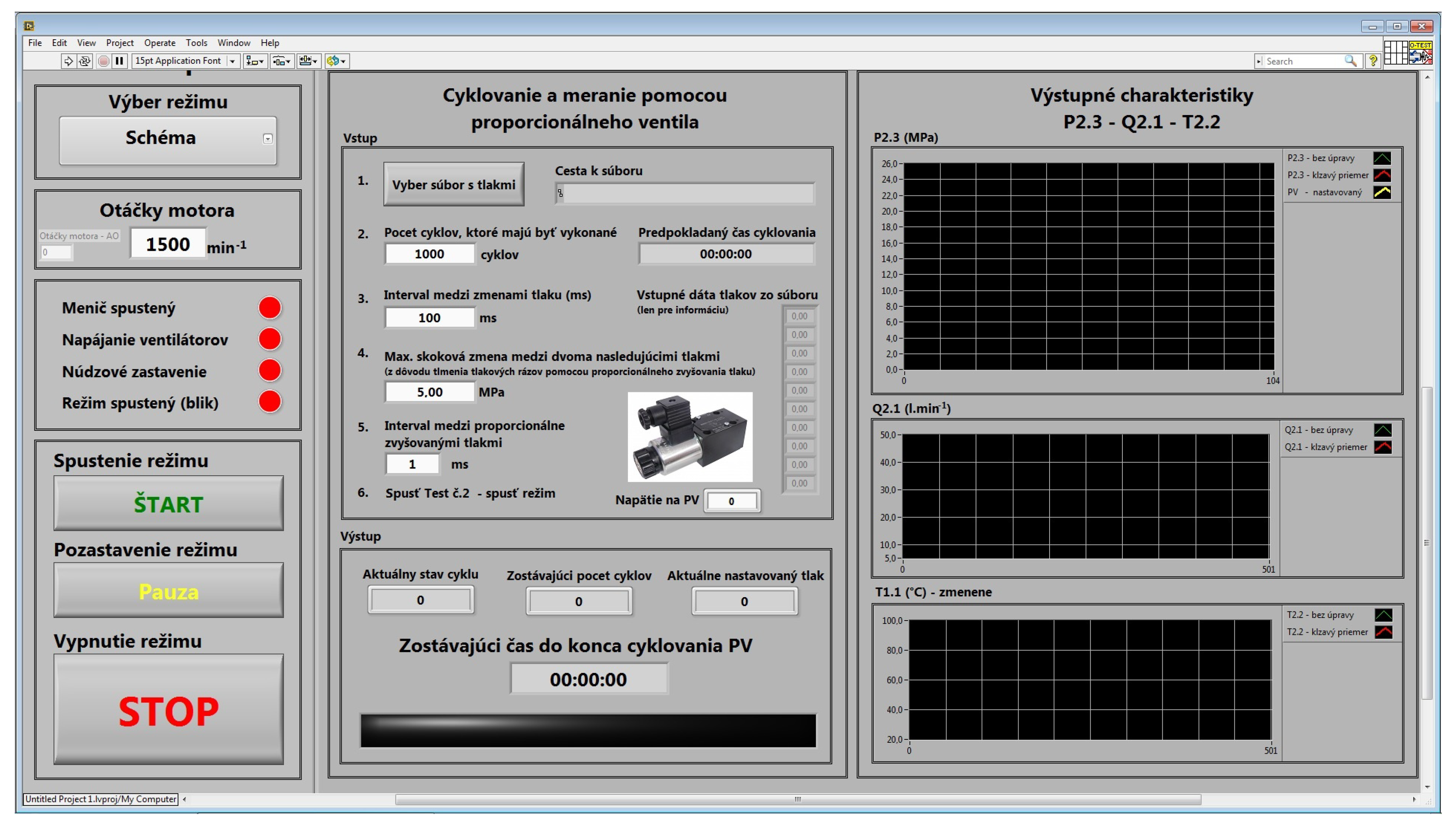
The control system software was created by the employees of the Technical Faculty, SUA in Nitra, Slovakia, in the LabVIEW software (Figure 7). LabVIEW is the integrated development environment for National Instruments visual programming language. LabVIEW is a development environment and uses a graphical programming syntax that makes it simple to visualize, create, and code engineering systems. The control system is built using blocks from the National Instruments company (Austin, TX, USA).
3.3. Verification Measurement of the Flow Characteristics of the Transducer
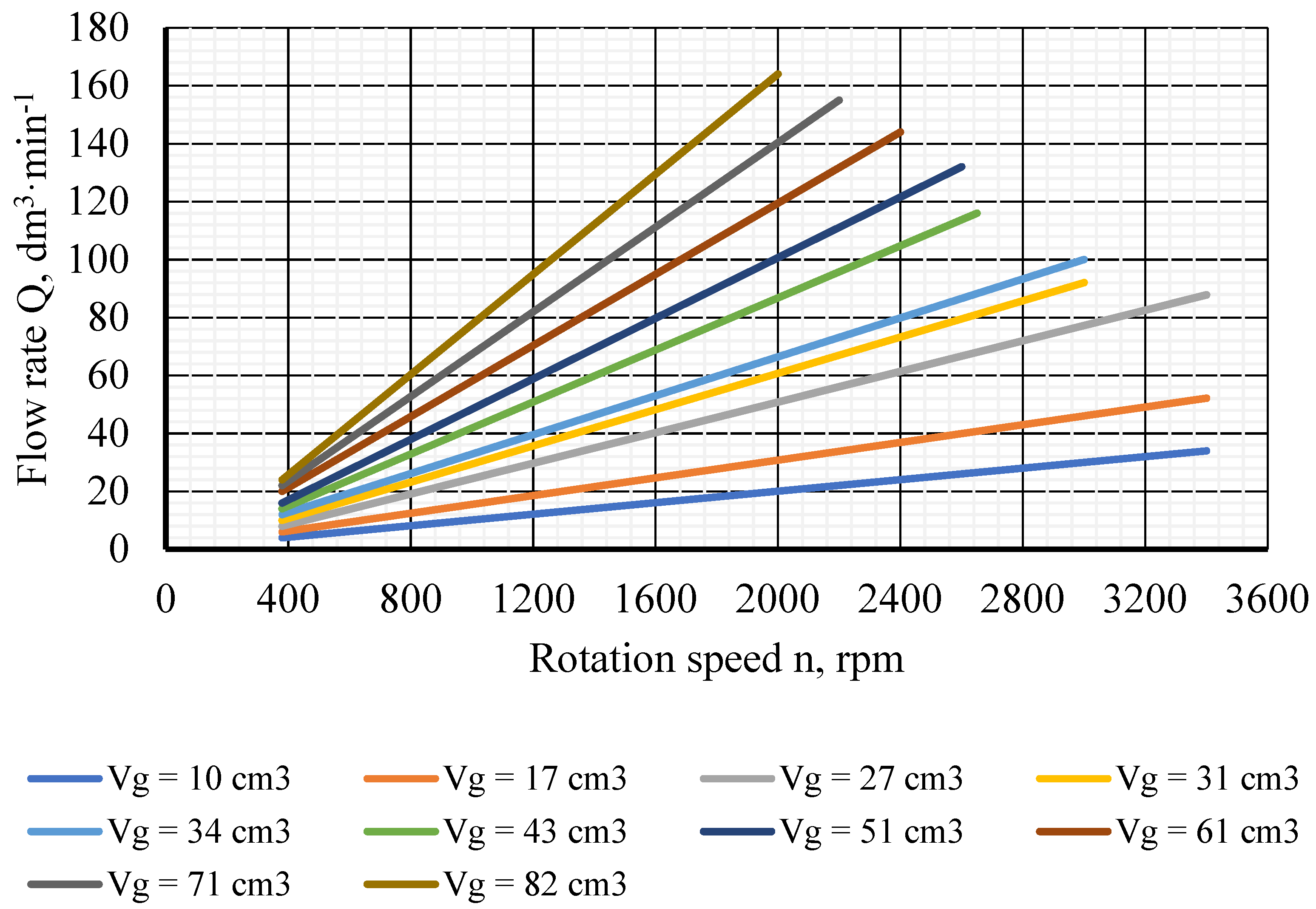
In the verification measurement of the flow characteristics of the hydrostatic transducers, we base ourselves on the data specified by the manufacturer. Figure 8 shows the flow characteristics of the transducers depending on the revolutions specified by the manufacturer. In the primary and secondary circuits of our hydraulic equipment, transducers with a geometric volume of VG = 17 cm3 were used.
Verification of the flow characteristics took 10 s at a sampling rate of 20 ms. The parameters were measured by the HMG 3010 measuring device, and flow, pressure, and temperature sensors by the HMG measuring device (Figure 2). The basic statistical evaluation of the verification of the flow characteristics of the transducers in the primary and secondary hydraulic circuit is shown in Table 8 and Table 9 and the flow rates in Figure 9 and Figure 10.
The verification measurement of the primary circuit of the laboratory test device was carried out in order to verify the function of individual elements of the test device, sensors, and control circuit C. Based on the evaluation of the verification measurement, it can be concluded that the test device is suitable for testing hydrostatic transducers, hydraulic circuit elements and simultaneous testing of various hydraulic fluids. The flow rate of the transducer in the proposed laboratory equipment corresponded to the values of the transducer manufacturer.
4. Discussion
Authors [11,21,22,23,24,25] dealt with the issue of testing hydrostatic transducers and hydraulic fluids in their work, and created a set of measuring laboratory equipment for testing hydrostatic elements and hydraulic fluids.
Authors [11] solved the design of a test equipment for parametric tests of hydraulic pumps used in an open hydraulic circuit, where a gearbox was included between the motor and the hydraulic pump, on the output shaft of which was located the torque sensor. The flow in the pressure part of the hydraulic circuit was measured by a high-pressure flow meter connected to the outlet of the hydraulic pump.
Authors [12] used an electro-hydraulic proportional pressure valve in the test case for dynamic loading of the hydraulic pump, by which the hydraulic motor and the hydraulic pump were loaded at the same time, while the hydraulic motor was firmly connected via a coupling connected to the hydraulic pump. The difference between the technical solution of the proposed hydraulic test equipment is that it allows the loading of hydrostatic transducers with operating pressure in the primary and secondary circuit simultaneously, but also separately. It is also possible to use an electro-hydraulic proportional valve to simulate the load only in the primary circuit, in case the circuits are mechanically disconnected after disconnecting the torque sensor.
Authors [26] describe a test device for the implementation of life tests of gear hydraulic pumps, where the cyclic compressive stress is provided by an electro-hydraulically controlled switchboard connected to the outlet of the hydraulic pump. The change in the position of the distributor resulted in a change in the flow of the fluid, which at the same time changed the pressure loading conditions at the outlet of the hydraulic pump.
As reported by [27], the authors used a pressure valve to change the pressure in the hydraulic circuit and to load the gear hydraulic pump, which derived the load by a gradual and uniform pressure rise (5 MPa each), and the result was a calculation of the flow efficiency of the hydraulic pump.
Authors [28] in their research verified the flow efficiencies of the hydraulic pump depending on the speed rotation, to increase the temperature of the operating fluid also used a throttle valve with stabilization, and the temperature was regulated via a heat exchanger (cooling device) and flow efficiencies were monitored at different fluid temperatures.
Authors [29] state in their work that a change in the flow efficiency of a hydraulic pump indicates such changes in the parameters of the hydraulic pump, it is also possible to evaluate the technical condition of the monitored hydraulic pump. Said monitoring of the technical condition of the hydraulic pump is also enabled by the proposed test laboratory equipment for monitoring the service life tests of the hydraulic pump, the technical condition of which will be assessed by changing the flow efficiency of the hydraulic pump.
It will be possible to monitor the service life of hydrostatic transducers under cyclic loading and dynamic loading with operating pressure on the proposed laboratory test equipment. Moreover, it is possible to monitor the influence of used hydraulic fluids on individual elements of the hydraulic system by monitoring changes in physico-chemical properties of hydraulic fluids. The proposed device is designed to allow a smooth change in the temperature of the working fluid by using a throttle valve with stabilization and regulation of air flow through the radiator, comparing the change in viscosity of the working fluid, as the temperature in the primary and secondary hydraulic circuit can be changed according to oil manufacturers.
5. Conclusions
The presented work includes the solution of the laboratory test equipment design, for testing hydrostatic transducers and hydraulic fluids used in mobile energy vehicles. Basic knowledge of the proposed solution was obtained gradually in the long-term research of the impact of agricultural, forestry, and transport technology on the environment in terms of the use of operating fluids with a focus on finding a suitable solution for the use of environmentally degradable oils [30,31]. It will be possible to use several diagnostic procedures of individual hydraulic elements on the proposed laboratory test equipment, such as tribodiagnostics, thermodiagnostics, in order to comprehensively assess the technical condition of the diagnosed object [4,32,33]. The technical solution of the proposed laboratory test equipment is the subject of approved patent 288635.
Fluids intended for the common transmission and hydraulic systems of tractors are exposed to specific conditions which are characteristic of agricultural production. Contamination causes several side effects such as accelerated wear, corrosion of steel surfaces, oxidation of oil, and changes in its physical and chemical properties [34,35]. Pollution has a very harmful effect, especially on ecological fluids because it accelerates the degradation processes [36]. Several authors [37,38,39] deal with the evaluation of hydraulic fluid during the operational test with subsequent analysis of polluting elements. The use of ecological fluids requires a high degree of purity of the oil filling [40]. The possibility of repeating the same operating load creates suitable conditions for assessing the influence of different types of energy carriers on the output parameters of individual hydrostatic transducers, thus enabling the creation of a model of the hydraulic system and determining its optimal parameters. The designed and implemented laboratory equipment for testing hydrostatic transducers and energy carriers (simultaneously in two circuits) is able to simulate with sufficient accuracy in laboratory conditions the pressure load of hydrostatic transducers. The proposed laboratory equipment is intended for measuring the qualitative properties of energy carriers by simulating operational loads. The aim of the contribution is the design and verification of laboratory equipment, which is used in the research of the degradation and simultaneous comparison of conventional fluid with biodegradable new type fluids and their influence on the flow characteristics of the used transducers. These types of fluids can be used as an energy carrier in machines working in ecologically sensitive areas. The mentioned device enables simultaneous testing of energy carriers, with a focus on biodegradable oils with the possibility of their use for machines working in an ecologically sensitive environment. This is a whole set of innovative technological procedures for the processing of biomass and its products in organic agriculture with a focus on the production of healthy food. For this reason, it is necessary to carry out laboratory tests before the introduction of new fluids, which reduce the risk of damage to the machine, shorten the test, and lower financial demands.
Author Contributions
Conceptualization and writing—original draft preparation, Ľ.H.; methodology, Ľ.H., J.J. and J.T.; formal analysis, Z.T. and Ľ.H.; writing—review and editing, J.T.; visualization, J.J. and Z.T. All authors have read and agreed to the published version of the manuscript.
Funding
This research received no external funding.
Institutional Review Board Statement
Not applicable.
Informed Consent Statement
Not applicable.
Data Availability Statement
Not applicable.
Acknowledgments
This publication was supported by the Operational Program Integrated Infrastructure within the project: Demand-driven research for the sustainable and innovative food, Drive4SIFood 313011V336, cofinanced by the European Regional Development Fund.
Conflicts of Interest
The authors declare that they have no known competing financial interests or personal relationships that could have appeared to influence the work reported in this paper.
References
- Markiewicz, P.M.; Kaszkowiak, J.; Borowski, S. The analysis of the Problems with Management of Wastes Generated by a Transport Company. Logistyka 2016, 5, 1135–1142. [Google Scholar]
- Hujo, Ľ.; Kangalov, P.G.; Kosiba, J. Laboratory Test Devices for Evaluating the Lifetime of Tractor Hydraulic Components: Proceedings, Methods and Application; Angel Kanchev University of Ruse: Ruse, Bulgaria, 2015. [Google Scholar]
- Kúčik, P. Excessive Noise from the Hydraulic System. 2018. Available online: http://fluidconsult.sk/nadmerny-hluk-hydraulickeho-systemu/ (accessed on 15 December 2021).
- Kosiba, J.; Čorňák, Š.; Glos, J. Monitoring Oil Degradation During Operating Tests. Agron. Res. 2016, 14, 1626–1634. [Google Scholar]
- Baroška, J. Hydrostatic Mechanisms; Hydropneutech, s.r.o.: Žilina, Slovakia, 2021; 388p, ISBN 978-80-970-8972-6. [Google Scholar]
- Winston, L.M. Fluid Power. Hydraulics & Pneumatics; Publisher Winston LM Smashwords Edition; Broadway: Oklahoma City, OK, USA, 2014; 159p, ISBN 978-13-101-6485-9. [Google Scholar]
- Mobley, K. Fluid Power Dynamics; Elsevier Sciens. & Tech.: Oxford, UK, 2000; 288p, ISBN 978-07-506-7174-3. [Google Scholar]
- Kim, J.; Sung-Gaun, K.A. Study of the Approximate Model of the Flow Rate Characteristics in External Gear Pump for EHPS. J. Korea Acad. Ind. Coop. Soc. 2013, 12, 548–553. [Google Scholar]
- Casoli, P.; Vacca, A.; Franzoni, G.A. Numerical Model for the Simulation of External Gear Pumps. In Proceedings of the 6th JFPS International Symposium on Fluid Power, Parma, Italy, 7–10 November 2005; pp. 705–710. [Google Scholar]
- Hujo, Ľ.; Jablonický, J.; Tkáč, Z. Design of Innovative Laboratory Simulation Device for Testing of Hydrostatic Transducers and Hydraulic Fluids; Slovak University of Agriculture in Nitra: Nitra, Slovakia, 2017. [Google Scholar]
- Drabant, Š.; Tkáč, Z.; Petranský, I. Measurement and Testing of Hydrostatic Elements and Systems; Slovak University of Agriculture in Nitra: Nitra, Slovakia, 2008. [Google Scholar]
- Petranský, I.; Drabant, Š.; Tkáč, Z.; Žikla, A.; Bolla, M.; Kleineder, P. Test Stands for Life Tests of Hydrostatic Converter; Slovak University of Agriculture in Nitra: Nitra, Slovakia, 2004. [Google Scholar]
- Tkáč, Z.; Drabant, Š.; Majdan, R.; Cvíčela, P. Testing Stands for Laboratory Tests of Hydrostatic Pump of Agricultural Machinery. Res. Agric. Eng. 2008, 54, 127–141. [Google Scholar] [CrossRef] [Green Version]
- Čorňák, Š. Identification of Operating Fluids with Fingerprint Method Utilization. In Proceedings of the 17th International Scientific Conference Engineering for Rural Development, Jelgava, Latvia, 23–25 May 2018; pp. 2035–2048. [Google Scholar]
- Hujo, Ľ.; Tkáč, Z.; Tulík, J.; Kosiba, J.; Uhrinová, D.; Jánošová, M. Monitoring of Operation Loading of Three-Point Linkage During Ploughing. Res. Agric. Eng. 2016, 62, 24–29. [Google Scholar] [CrossRef] [Green Version]
- Hujo, Ľ.; Čorňák, Š.; Tkáč, Z.; Jánošová, M. Laboratory Research of Transmission-Hydraulic Fluid. In Proceedings of the 7th International Conference on Trends in Agricultural Engineering, Prague, Czech Republic, 17–20 September 2019; pp. 17–20. [Google Scholar]
- Hujo, Ľ.; Jablonický, J.; Markovič, J.; Tulík, J.; Simikić, M.; Zastempowski, M.; Janoušková, R. Design of Laboratory Test Equipment for Automotive Oil Filters to Evaluate the Technical Life of Engine Oil. Appl. Sci. 2021, 11, 483. [Google Scholar] [CrossRef]
- Hujo, Ľ.; Nosian, J.; Zastempowski, M.; Kosiba, J.; Kaszkowiak, J.; Michalides, M. Laboratory Test of the Hydraulic Pump Operating Load with Monitoring of Changes in the Physical Properties. Meas. Control. 2021, 54, 243–251. [Google Scholar] [CrossRef]
- Majdan, R.; Tkáč, Z.; Abrahám, R.; Szabó, M.; Halenár, M.; Rášo, M.; Ševčík, P. Proposal for Filtration System for Biodegradable Lubricants in Agricultural Tractors. Agron. Res. 2016, 14, 1395–1405. [Google Scholar]
- Simikić, M.; Dedović, N.; Savin, L.; Tomić, M.; Ponjičan, O. Power Delivery Efficiency of a Wheeled Tractor at Oblique Drawbar Force. Soil Tillage Res. 2014, 141, 32–43. [Google Scholar] [CrossRef]
- Cvíčela, P.; Majdan, R.; Abrahám, R. Operating load of the Zetor Forterra tractor hydrogenerator. In Proceedings of the 34th International Conference of Departments of Transport, Handling Construction and Agricultural Machinery, Ostrava, Czech Republic, 24–26 September 2008; pp. 24–26. [Google Scholar]
- Janoško, I.; Polonec, T.; Lindák, S. Performance Parameters Monitoring of the Hydraulic System with Bio-Oil. Res. Agric. Eng. 2014, 60, 37–43. [Google Scholar] [CrossRef] [Green Version]
- Kučera, M.; Aleš, Z.; Pexa, M. Detection and Characterization of Wear Particles of Universal Tractor Oil Using of Particles Size Analyser. Agron. Res. 2016, 14, 1351–1360. [Google Scholar]
- Tessmann, K.R. Qualification of Hydraulic Fluid through Pump Testing. In Proceedings of the International Fluid Power Exposition and Technical Conference, Chicago, IL, USA, 8–12 April 1996. [Google Scholar]
- Turza, J.; Kopiláková, B. Combined stand for measuring of hydraulic elements. J. Hydraul. Pneum. Autom. Technol. 2011, 1–2, 60–64. [Google Scholar]
- Tkáč, Z.; Majdan, R.; Drabant, Š.; Jablonický, J.; Abrahám, R.; Cvíčela, P. The accelerated laboratory test of biodegradable fluid type “ertto”. Res. Agric. Eng. 2010, 56, 18–25. [Google Scholar] [CrossRef] [Green Version]
- Dobrota, D.; Lalič, B.; Oršulič, M. Experimental Modeling of Volumetric Utility High Pressure Gear Pumps with External Gear. Naše More Znan. Časopis More Pomor. 2010, 57, 235–240. [Google Scholar]
- Yoshida, N.; Inaguma, Y. Mathematical Analysis of Efficiencies in Hydraulic Pumps for Automatic Transmissions. JTEKT Eng. J. 2014, 1011E, 64–73. [Google Scholar]
- Libra, M.; Poulek, V. Energy Sources and Their Use; Czech University of Life Sciences Prague: Prague, Czech Republic, 2014. [Google Scholar]
- Jablonický, J.; Simikić, M.; Tulík, J.; Tomić, M.; Hujo, Ľ.; Kosiba, J. Monitoring of Selected Physical and Chemical Parameters of Test Oil in the Wet Disc Brake System. Acta Technol. Agric. 2020, 23, 46–52. [Google Scholar] [CrossRef] [Green Version]
- Máchal, P.; Tkáč, Z.; Kosiba, J.; Jablonický, J.; Hujo, Ľ.; Kučera, M.; Tulik, J. Design of a Laboratory Hydraulic Device for Testing of Hydraulic Pumps. Acta Univ. Agric. Silvic. Mendel. Brun. 2013, 61, 1313–1319. [Google Scholar] [CrossRef] [Green Version]
- Kaszkowiak, J.; Borowski, S.; Kaszkowiak, E.; Dulcet, E.; Zastempowski, M.; Hujo, Ľ. Air filtering systems in power supply systems of internal combustion engines in working machines. Logistyka 2015, 4, 1893–1898. [Google Scholar]
- Nosian, J.; Hujo, Ľ.; Zastempowski, M.; Janoušková, R. Design of Laboratory Test Equipment for Testing the Hydrostatic Transducers. Acta Technol. Agric. 2021, 24, 35–40. [Google Scholar] [CrossRef]
- Kučera, M.; Majdan, R.; Abrahám, R.; Kučera, M.; Haas, P. Analysis of the effect of loading process on tribological system properties. Acta Univ. Agric. Silvic. Mendel. Brun. 2016, 64, 825–833. [Google Scholar]
- Tóth, F.; Fürstenzeller, A.; Rusnák, J.; Bošanský, M.; Kadnár, M. The Possibilities of Using Ecological Liquids in Tribological Gliding Systems with a Selected Surface Created by the Radial Welding Technology. Acta Technol. Agric. 2019, 22, 134–139. [Google Scholar] [CrossRef] [Green Version]
- Majdan, R.; Tkáč, Z.; Abrahám, R.; Kollárová, K.; Vitázek, I.; Halenár, M. Filtration Systems Design for Universal Oils in Agricultural Tractors. Tribol. Ind. 2017, 39, 547–558. [Google Scholar] [CrossRef] [Green Version]
- Halenár, M.; Kuchar, P. Research of Biodegradable Fluid During Operating Test. In Proceedings of the 24th International PhD Students Conference (MendelNet), Brno, Czech Republic, 8–9 November 2017. [Google Scholar]
- Tkáč, Z.; Čorňák, Š.; Cviklovič, V.; Kosiba, J.; Glos, J.; Jablonický, J.; Bernát, R. Research of Biodegradable Fluid Impacts on Operation of Tractor Hydraulic System. Acta Technol. Agric. 2017, 20, 42–45. [Google Scholar] [CrossRef] [Green Version]
- Zastempowski, M. Test Stands with Energy Recovery System for Machines and Hydraulic Transmissions. Agric. Eng. Res. 2013, 58, 188–191. [Google Scholar]
- Kopiláková, B.; Turza, J.; Hujo, Ľ.; Kosiba, J. Evaluation of Hydraulic Resistance in Various Liquids and Temperature. Tribol. Ind. 2017, 39, 129–135. [Google Scholar] [CrossRef] [Green Version]
Figure 1.
Theoretical course of the load cycle.

Figure 2.
(a) Measuring device HMG 3010; (b) flow, pressure, and temperature sensors for HMG measuring device.
Figure 2.
(a) Measuring device HMG 3010; (b) flow, pressure, and temperature sensors for HMG measuring device.

Figure 3.
Connection of hydraulic motor and hydraulic pump with combined speed rotation and torque sensor.
Figure 3.
Connection of hydraulic motor and hydraulic pump with combined speed rotation and torque sensor.

Figure 4.
Schematic of the proposed laboratory test equipment.

Figure 5.
A view of the implemented test equipment.

Figure 6.
Schematic of the primary circuit of a laboratory test equipment with connection of an electro-hydraulic proportional pressure valve.
Figure 6.
Schematic of the primary circuit of a laboratory test equipment with connection of an electro-hydraulic proportional pressure valve.

Figure 7.
Control system of proposed laboratory equipment in LabVIEW.

Figure 8.
Flow characteristics of the transducers QHD-17R determined by the manufacturer.

Figure 9.
Flow characteristics of the transducers in the primary circuit.

Figure 10.
Flow characteristics of the transducers in the secondary circuit.


Table 1.
Hydraulic gear pump GHD1-17R-S2D1-SG05G04-N.
| Parameter | Unit | Value | |
|---|---|---|---|
| Actual displacement | cm3 | 17.39 | |
| Pressure at inlet maximum | MPa | 0.05 | |
| Pressure at outlet maximum | MPa | 30.00 | |
| Rotation speed | Nominal | rpm | 1500 |
| Minimum | rpm | 400 | |
| Maximum | rpm | 3200 | |
| Sense of rotation | - | right | |
| Flow at maximum speed rotation | dm3 min−1 | 54.5 | |
Table 2.
Hydraulic gear pump GHD0-17R-S2D2-SG05G04-N.
| Parameter | Unit | Value | |
|---|---|---|---|
| Actual displacement | cm3 | 16.951 | |
| Pressure at inlet maximum | MPa | 0.06 | |
| Pressure at outlet maximum | MPa | 30.00 | |
| Rotation speed | Nominal | rpm | 1500 |
| Minimum | rpm | 350 | |
| Maximum | rpm | 3400 | |
| Sense of rotation | - | right | |
| Flow at maximum speed rotation | dm3 min−1 | 56.5 | |
Table 3.
Hydraulic gear motor QM2 17.0.
| Parameter | Unit | Value | |
|---|---|---|---|
| Actual displacement | cm3 | 17.24 | |
| Pressure at inlet maximum | MPa | 0.05 | |
| Pressure at outlet maximum | MPa | 29.00 | |
| Rotation speed | Nominal | rpm | 1500 |
| Minimum | rpm | 350 | |
| Maximum | rpm | 3200 | |
| Sense of rotation | - | right | |
| Flow at maximum speed rotation | dm3 min−1 | 54.3 | |
Table 4.
Torque sensor HBM Stator T12.
| Parameter | Unit | Value |
|---|---|---|
| Torque nominal | Nm | 2 |
| Speed rotation maximum | rpm | 12,000 |
| Voltage | V | 10 |
| Voltage in start mode | A | <4 |
| Voltage in measuring mode | A | <1 |
Table 5.
Input parameters.
| Parameter | Unit | Value | |
|---|---|---|---|
| Nominal combustion engine speed rotation | rpm | 2200 | |
| Actual displacement | cm3 | 16.28 | |
| Flow through hydraulic pump | dm3/min | 22.22 | |
| Rotation speed | Nominal | rpm | 1500 |
| Minimum | rpm | 400 | |
| Maximum | rpm | 3200 | |
| Pressure in hydraulic circuit | Permanent | MPa | 25 |
| Maximum | MPa | 26 | |
| Efficiency | Volume | - | 0.91 |
| Mechanical | - | 0.85 | |
| Overall | - | 0.77 | |
Table 6.
Calculated values of the input hydraulic pump for the design of the electric motor.
| Parameter | Unit | Value | |
|---|---|---|---|
| Flow through hydraulic pump at | Minimum speed rotations | rpm | 6.67 |
| Nominal speed rotations | rpm | 22.22 | |
| Maximum speed rotations | rpm | 47.41 | |
| Torque at | Minimum speed rotations | Nm | 79.30 |
| Nominal speed rotations | |||
| Maximum speed rotations | |||
| Power | Minimum speed rotations | kW | 4.10 |
| Nominal speed rotations | kW | 13.68 | |
| Maximum speed rotations | kW | 29.19 | |
Table 7.
Design of electric motor parameters.
| Parameter | Unit | Value |
|---|---|---|
| Power | kW | 30 |
| Torque | Nm | 80 |
| Speed rotations minimum | rpm | 450 |
| Speed rotations maximum | rpm | 2950 |
| Protection class acc. To DIN 40050 | IP | 55 |
| Voltage | - | 400/690 V |
| Efficiency | % | 92 |
Table 8.
Basic statistical evaluation, verification of flow characteristics of transducers in the primary circuit.
Table 8.
Basic statistical evaluation, verification of flow characteristics of transducers in the primary circuit.
| Flow Rate Q | Average | Median | Mode | Minimum | Maximum | Distraction | Standard Deviation | Variation Coefficient |
|---|---|---|---|---|---|---|---|---|
| Rotation speed | Me | Mo | xmin | xmax | σ2 | σ | Vk | |
| 500 | 7.6446 | 7.65 | 7.77 | 7.21 | 7.99 | 0.033 | 0.182 | 2.388 |
| 750 | 11.753 | 11.77 | 11.74 | 11.27 | 12.26 | 0.043 | 0.207 | 1.766 |
| 1000 | 16.032 | 16.03 | 16.21 | 15.25 | 16.84 | 0.093 | 0.305 | 1.903 |
| 1250 | 20.080 | 20.08 | 20.06 | 19.41 | 20.88 | 0.088 | 0.297 | 1.480 |
| 1500 | 24.098 | 24.10 | 24.02 | 23.36 | 24.93 | 0.106 | 0.326 | 1.354 |
| 1750 | 28.192 | 28.19 | 28.25 | 27.43 | 28.96 | 0.108 | 0.328 | 1.166 |
| 2000 | 32.323 | 32.32 | 32.34 | 31.60 | 33.03 | 0.100 | 0.317 | 0.981 |
Table 9.
Basic statistical evaluation, verification of flow characteristics of transducers in the secondary circuit.
Table 9.
Basic statistical evaluation, verification of flow characteristics of transducers in the secondary circuit.
| Flow Rate Q | Average | Median | Mode | Minimum | Maximum | Distraction | Standard Deviation | Variation Coefficient |
|---|---|---|---|---|---|---|---|---|
| Rotation speed | Me | Mo | xmin | xmax | σ2 | σ | Vk | |
| 500 | 7.52 | 7.51 | 7.53 | 7.44 | 7.60 | 0.0007 | 0.026 | 0.351 |
| 750 | 11.71 | 11.71 | 11.68 | 11.57 | 11.80 | 0.001 | 0.030 | 0.263 |
| 1000 | 15.94 | 15.91 | 15.94 | 15.65 | 16.20 | 0.0013 | 0.036 | 0.227 |
| 1250 | 20.14 | 20.14 | 20.08 | 19.62 | 20.77 | 0.0591 | 0.243 | 1.207 |
| 1500 | 24.40 | 24.39 | 24.28 | 23.77 | 24.92 | 0.0960 | 0.309 | 1.270 |
| 1750 | 28.60 | 28.62 | 28.45 | 28.10 | 29.07 | 0.0733 | 0.270 | 0.946 |
| 2000 | 32.76 | 32.76 | 32.81 | 32.32 | 33.16 | 0.05002 | 0.223 | 0.682 |
Publisher’s Note: MDPI stays neutral with regard to jurisdictional claims in published maps and institutional affiliations. |
© 2022 by the authors. Licensee MDPI, Basel, Switzerland. This article is an open access article distributed under the terms and conditions of the Creative Commons Attribution (CC BY) license (https://creativecommons.org/licenses/by/4.0/).
Share and Cite
MDPI and ACS Style
Hujo, Ľ.; Jablonický, J.; Tkáč, Z.; Tulík, J. Design of Test Equipment for Hydrostatic Transducers and Hydraulic Fluids. Appl. Sci. 2022, 12, 7777. https://0-doi-org.brum.beds.ac.uk/10.3390/app12157777
AMA Style
Hujo Ľ, Jablonický J, Tkáč Z, Tulík J. Design of Test Equipment for Hydrostatic Transducers and Hydraulic Fluids. Applied Sciences. 2022; 12(15):7777. https://0-doi-org.brum.beds.ac.uk/10.3390/app12157777
Chicago/Turabian StyleHujo, Ľubomír, Juraj Jablonický, Zdenko Tkáč, and Juraj Tulík. 2022. "Design of Test Equipment for Hydrostatic Transducers and Hydraulic Fluids" Applied Sciences 12, no. 15: 7777. https://0-doi-org.brum.beds.ac.uk/10.3390/app12157777
Note that from the first issue of 2016, this journal uses article numbers instead of page numbers. See further details here.