
Centrifuge Model Investigation of Interaction between Successively Constructed Foundation Pits


1
Department of Geotechnical Engineering, Tongji University, Shanghai 200092, China
2
Department of Civil Engineering, University of Shanghai for Science and Technology, Shanghai 200093, China
*
Author to whom correspondence should be addressed.
Appl. Sci. 2022, 12(16), 7975; https://0-doi-org.brum.beds.ac.uk/10.3390/app12167975
Submission received: 30 June 2022
/
Revised: 5 August 2022
/
Accepted: 6 August 2022
/
Published: 9 August 2022
(This article belongs to the Special Issue Recent Progress on Advanced Foundation Engineering)
Abstract
:A series of centrifuge model tests were conducted to study the interaction between successively constructed adjacent foundation pits. The stress, deformation, and earth pressure on retaining structures and the settlement of the soil between the two adjacent foundation pits during successive construction were investigated by a comprehensive instrumentation program. To reveal the effect of the construction sequence, both the stress and deformation of successively constructed foundation pits were compared. The results showed that the stress and deformation of the retaining structure in the foundation pit constructed first were larger than those in the foundation pit constructed later. Due to the inward displacement of the soil around the foundation pits excavated first, the first strut of the foundation pit constructed later underwent high tension during the construction of the first foundation pit. The lateral deformation of the retaining structure of the foundation pit excavated first increased with the increase of the excavation depth. However, the excavation of the second foundation pit reduced the earth pressure on the retaining wall between the two excavations, thus leading to the recovery of the inward deformation in the first excavation. However, the top of the retaining wall deformed into the first foundation pit during the whole construction. The settlement of the soil between the two foundation pits showed a superposition effect. During the construction of the two foundation pits, the settlement of the soil between them kept increasing. The active earth pressure on the middle wall of the foundation pit constructed later was lower than that on the middle wall of the first foundation pit. The excavation of the foundation pit constructed later had no significant effect on the passive earth pressure of the first foundation pit.
1. Introduction
When constructing large-scale underground spaces, many foundation pit projects are typically required. In this context, many group pit and adjacent foundation pit projects have been constructed. Many scholars have studied foundation pit engineering, but most of them have focused on the characteristics of a single foundation pit [1,2,3,4,5,6] and their impact on the surrounding environment [7,8,9,10,11,12,13,14]. Research on foundation pit groups is less common, and to the best of our knowledge, only a few of these studies using numerical analyses and case studies are available.
On the contrary, theoretical research and experimental research on foundation pit groups [15,16,17,18,19] are even rarer. Li [20] studied the mechanical deformation characteristics of adjacent retaining structures by describing the interaction of the soil between pits using theoretical derivation and numerical simulation. Hu [21] studied the deformation mechanism of two adjacent foundation pits in a cross construction using field measurement and numerical analysis. Tao [22] compared the construction responses of a single foundation pit and a double foundation pit group via a numerical analysis, and the impact of the adjacent foundation pit on the foundation pit constructed first was analyzed. Geotechnical centrifuge tests have also been widely used to study ultradeep and ultra-large-scale foundation pits due to their unique advantages [23,24,25,26,27]. Liang et al. [28] studied the stress and deformation of deep foundation pits near metro hubs through centrifuge model tests and three-dimensional finite element numerical simulations. Ma et al. [29] investigated the deformation of retaining structures, changes in earth pressure, and the surface settlement of ultradeep foundation pits under two groups of working conditions using centrifugal model tests based on an ultradeep foundation pit project with a depth of 38 m in Shanghai. Due to the complex centrifuge test process and the limited size of the centrifuge model box, there are few reports of studies using centrifuge tests to investigate the interaction within a foundation pit group. In this study, a centrifuge test was performed to simulate the sequential construction of two adjacent foundation pits often encountered in engineering, and the interaction between the two foundation pits was analyzed.
2. Centrifugal Model Test Design
A centrifuge model test was performed in the Key Laboratory of Geotechnical and Underground Engineering at the Department of Geotechnical Engineering of Tongji University. The test model was a tlj-150 composite geotechnical centrifuge, and the centrifuge model test was performed using a geotechnical centrifuge, which placed the geotechnical test model in the centrifuge model box according to the design requirements. When the model box rotated at a high speed, the model experienced the effect of gravitational acceleration to compensate for the scaled gravitational loss of geotechnical structures. A centrifugal force equivalent to gravity was applied to make the stress level and deformation of the model soil and the prototype soil the same to provide a reference for theoretical research and numerical methods. In a centrifuge model test, the hypergravity model on a small scale can achieve the stress level of a large-scale prototype in Earth’s gravity. Moreover, many long-term phenomena in Earth’s gravity can also be reproduced on an observable timescale in centrifuge model tests [30,31,32].
In this study, the centrifuge test simulated the successive construction process of adjacent foundation pits. Compared with a single foundation pit, the required model size was larger. Combined with the influence of the boundary effect, the operability of the test process, the stable working conditions of the centrifuge, and the existing test experience of the centrifuge, it was important to properly select the size and similarity range of the model. On the basis of these considerations, the acceleration during the stable operation of the centrifuge model test was 100 G (G is gravitational acceleration), and the corresponding model similarity rate was 1:100.
Compared with cohesive soil, sandy soil has better characteristics suitable for centrifuge tests. For example, sandy soil can be used in a high-quality centrifugal simulation if certain preparation methods, including certain compactness, are followed [26]. Therefore, standard sand was used in this model test, and the soil parameters are shown in Table 1. In this model test, the retaining wall and support of the foundation pit were made of aluminum alloy instead of reinforced concrete, and the thickness of the alternative material was determined according to the principle of similar flexural stiffness to the prototype material model [12]. The converted model dimensions are shown in Table 2.
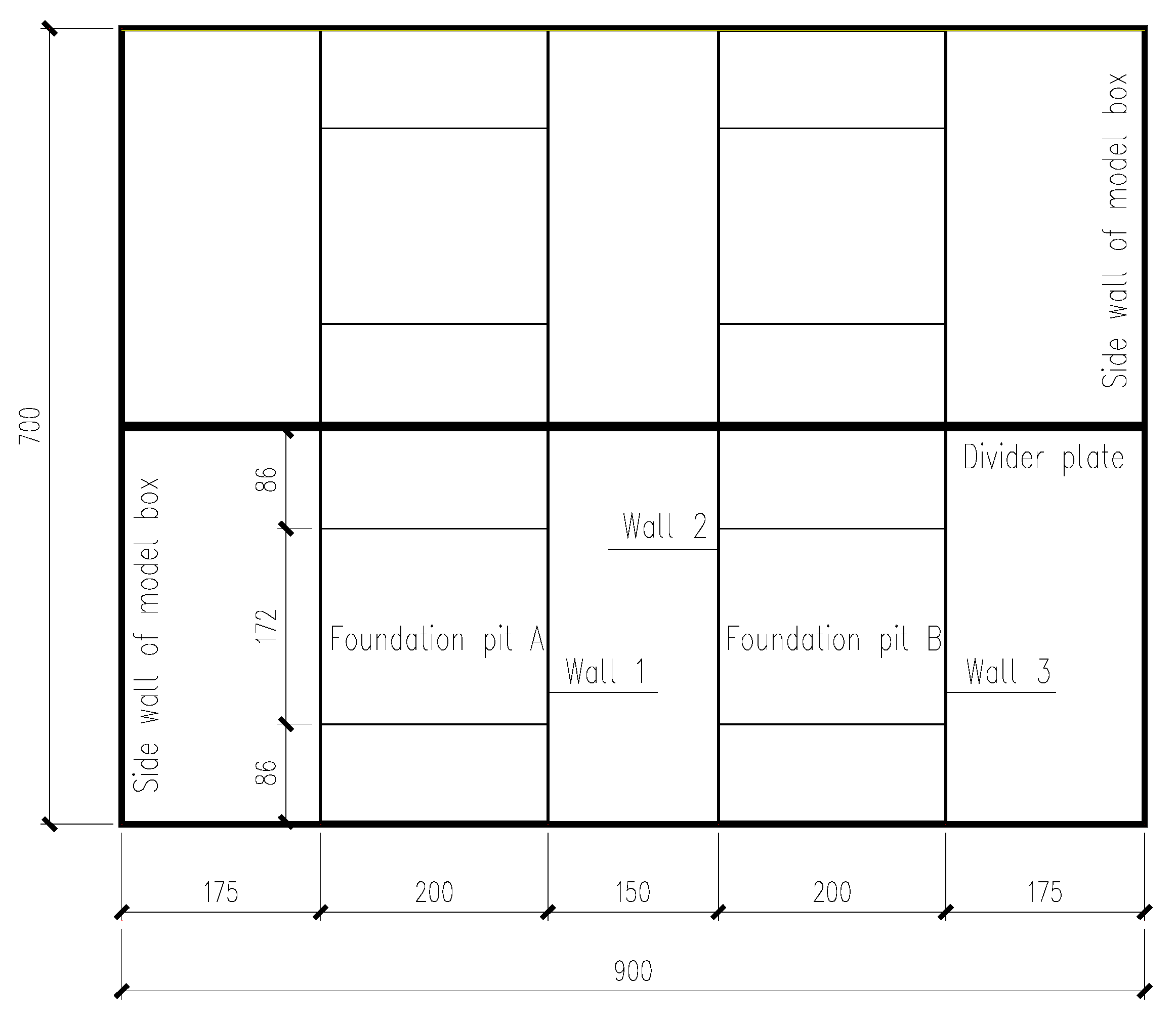
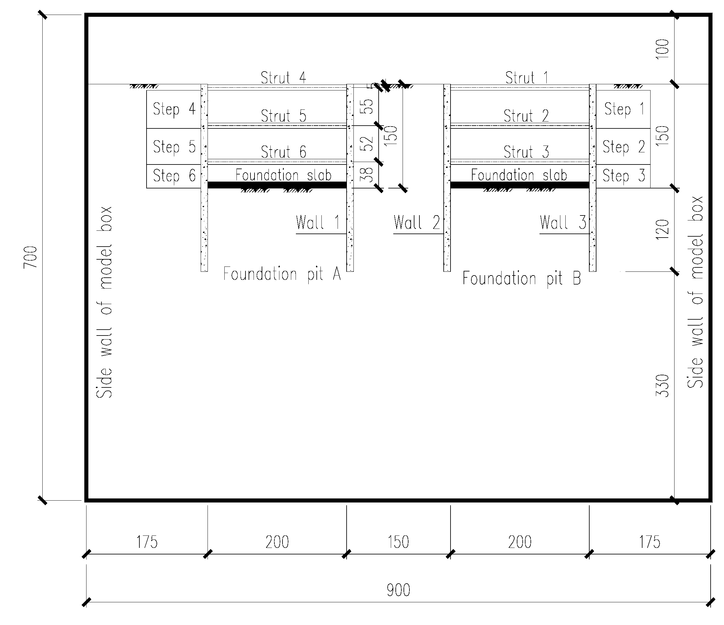
The size of the model box used in this test was 900 mm × 700 mm × 700 mm (length, width, and height). The original test design was divided into two areas through the middle partition with a certain stiffness. Because some channels were damaged during the test, it was adjusted to select half of the areas for the centrifuge test. The size of the selected area was 900 mm × 346 mm × 600 mm (length, width, and height). A thick aluminum alloy plate was selected for the diaphragm, both sides of the bottom were reinforced with corbel, and silica gel was used to seal between both ends of the diaphragm and the sidewall of the model box to prevent the outflow of sand. After preparing the soil sample and installing all the components, the total weight of the model box was approximately 1100 kg, and the design capacity was 150·g centrifuge equipment that could operate smoothly under 100·g acceleration. The centrifuge model test simulated two adjacent deep foundation pit projects, and three reinforced concrete supports were set along the depth direction. According to the usual practice of real engineering construction, the ground walls of the two foundation pits were constructed concurrently. Before the foundation pit excavation, the first support of the two foundation pits was installed. The plan and section of the model test are shown in Figure 1 and Figure 2.
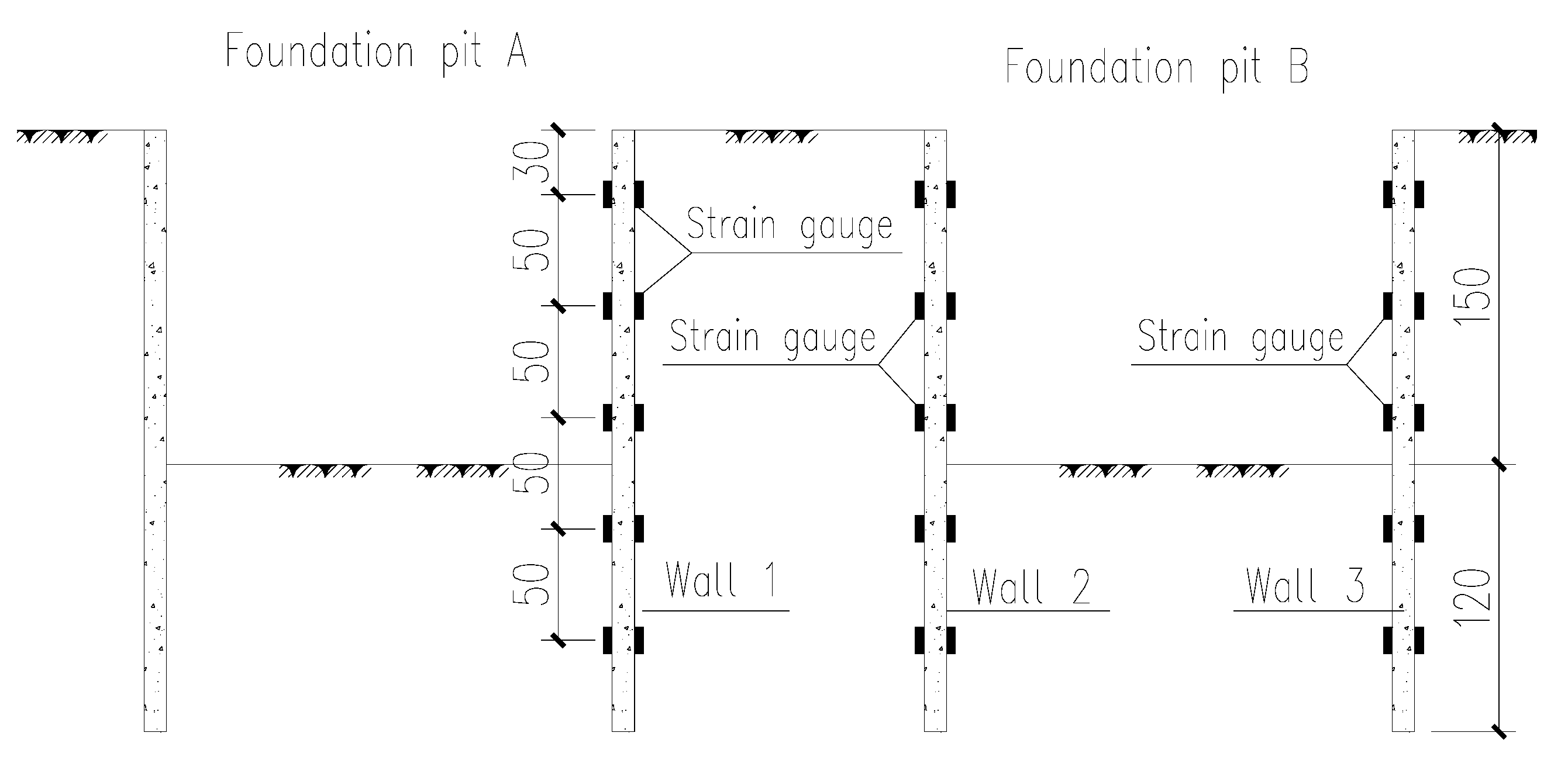
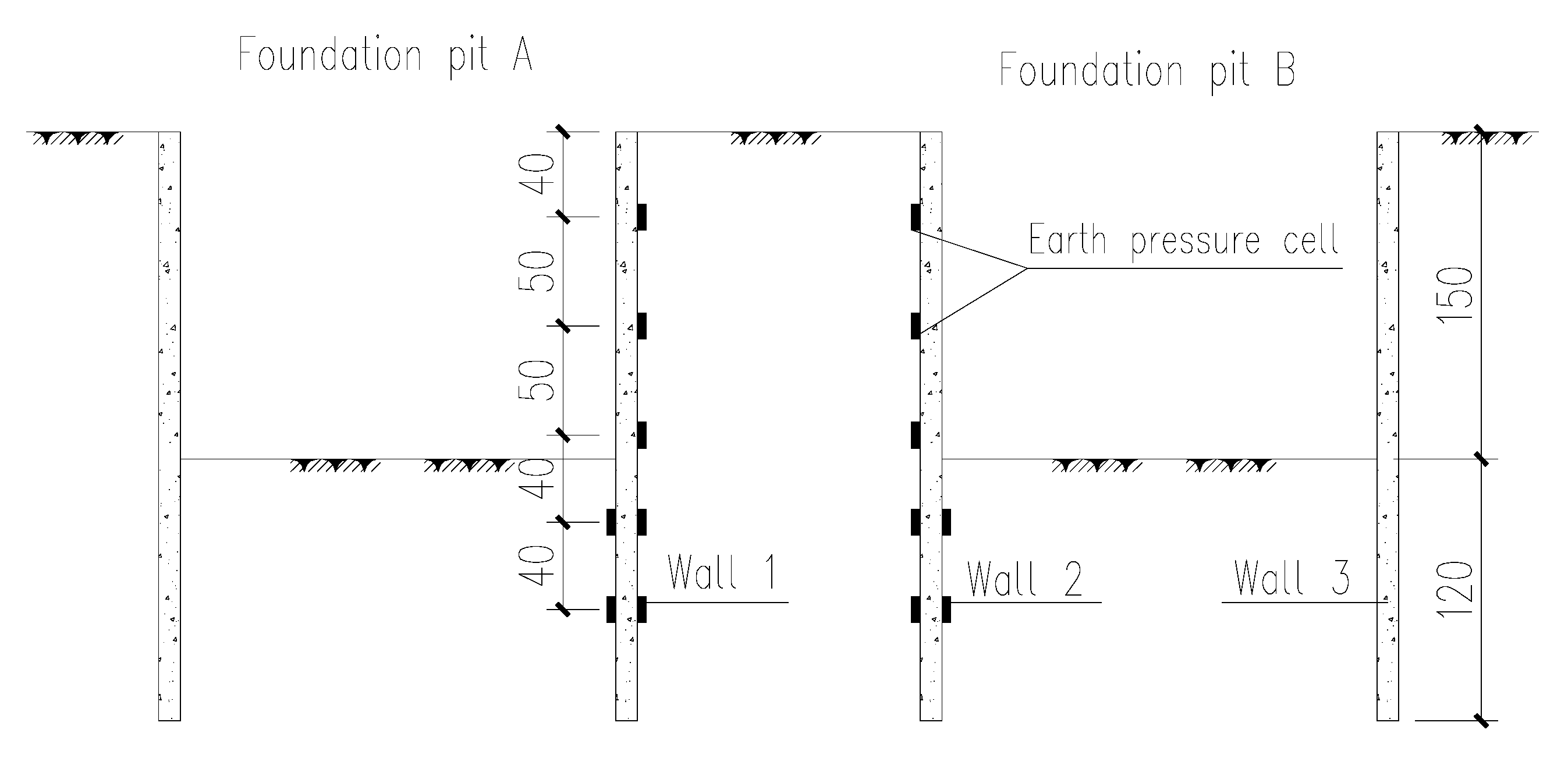
In this centrifuge test, the wall bending moment of each wall was converted, and the horizontal displacement of the wall body along the depth direction was calculated using measurements from the strain gauges that were pasted on the ground walls of the two adjacent foundation pits. The resistive strain gauges were used in this study, and the grid length × grid width of the gauge was 5 mm × 3 mm. Concurrently, a laser displacement meter was set on the tops of the two adjacent walls to directly measure the horizontal displacement of the wall top. The arrangement of the strain gauges is shown in Figure 3. To determine the change in earth pressure, earth pressure gauges were pasted onto two adjacent ground walls in the middle of the two foundation pits to measure the active earth pressure under various working conditions. The arrangement of earth pressure cells is shown in Figure 4. Additionally, strain gauges were pasted on each support of the foundation pit to determine the support axial force under various working conditions. For the convenience of description, two adjacent foundation pits and their components were numbered accordingly, as shown in Figure 1 and Figure 2.
There are typically three methods used to simulate foundation pit excavation: stop–start–stop excavation, the liquid drainage method, and micro-machine excavation. Considering the feasibility of various excavation schemes and the previous test experience undertaken by the centrifuge equipment used in this test, the traditional stop–start–stop excavation mode, which is relatively easy to operate, was used as the excavation scheme in this study. Furthermore, according to Xu et al. [26], the intermittent rotation has little effect on the deformation of standard sand. In this regard, the shutdown time for soil excavation and support installation was about 20 min during the centrifuge simulation. During the centrifuge test, the simulated excavation time was primarily determined according to the construction time of the prototype project and the continuous stability time of the data from the start-up of the centrifuge to the set acceleration. According to the similarity principle of the centrifuge, the ratio of model time to prototype time is 1:n2 [30]. In this test, the length of the corresponding prototype foundation pit was approximately 35 m, and the width was approximately 20 m. Considering the concrete curing time and the earth excavation time, 15 days were required for each layer of soil excavation and the installation of the support. Therefore, according to the similarity relationship, in the 100·g centrifugal field, the centrifugal acceleration would be stable for 3 min after loading from 0 to 100·g, which is equivalent to a construction period of 21 days. During the test, from the application of the first support, the acceleration of the centrifuge changed from 0·g to 100·g for 3 min. Then, the machine was stopped for excavation, and once the excavation was completed, the machine was started again to change the acceleration from 0·g to 100·g for 3 min. This process was repeated to complete the excavation under each working condition. The overall construction sequence was to construct foundation pit B first and then foundation pit A. Foundation pit A was excavated after the underground structure of foundation pit B was completed. The detailed construction and excavation process is shown in Table 3.
Two methods are commonly used to calculate the displacement by strain: the first involves calibrating the strain gauge of each component, converting the calibration data with the direct reading to obtain the bending moment of the ground wall, and then obtaining the displacement by fitting the bending moment and combining the boundary conditions [24,28]; the second method involves directly deducing the deformation and bending moment from the strain using the pure bending model of the elastic beam combined with a certain erection through the measured strain readings [33]. In this test, the first method was used to calculate the bending moment of the diaphragm wall and the horizontal displacement of the wall body.
3. Analysis of Test Results
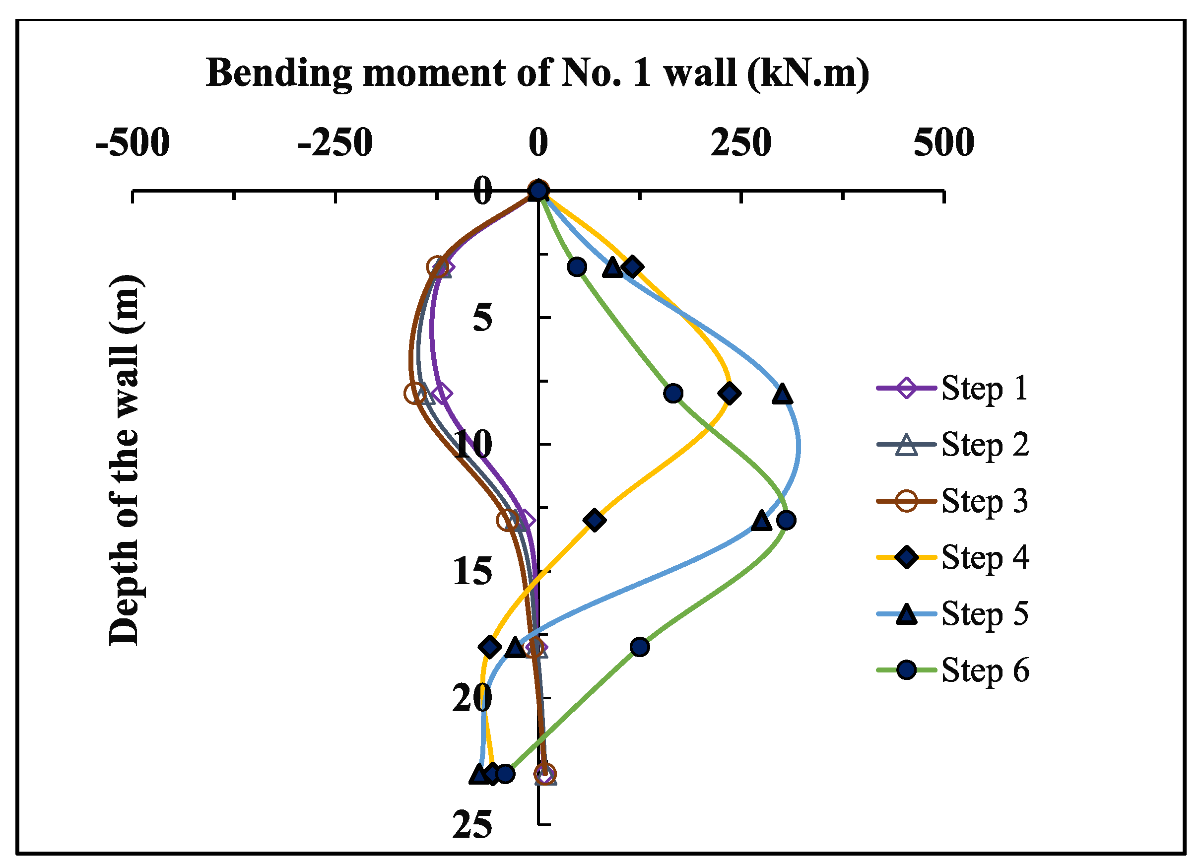
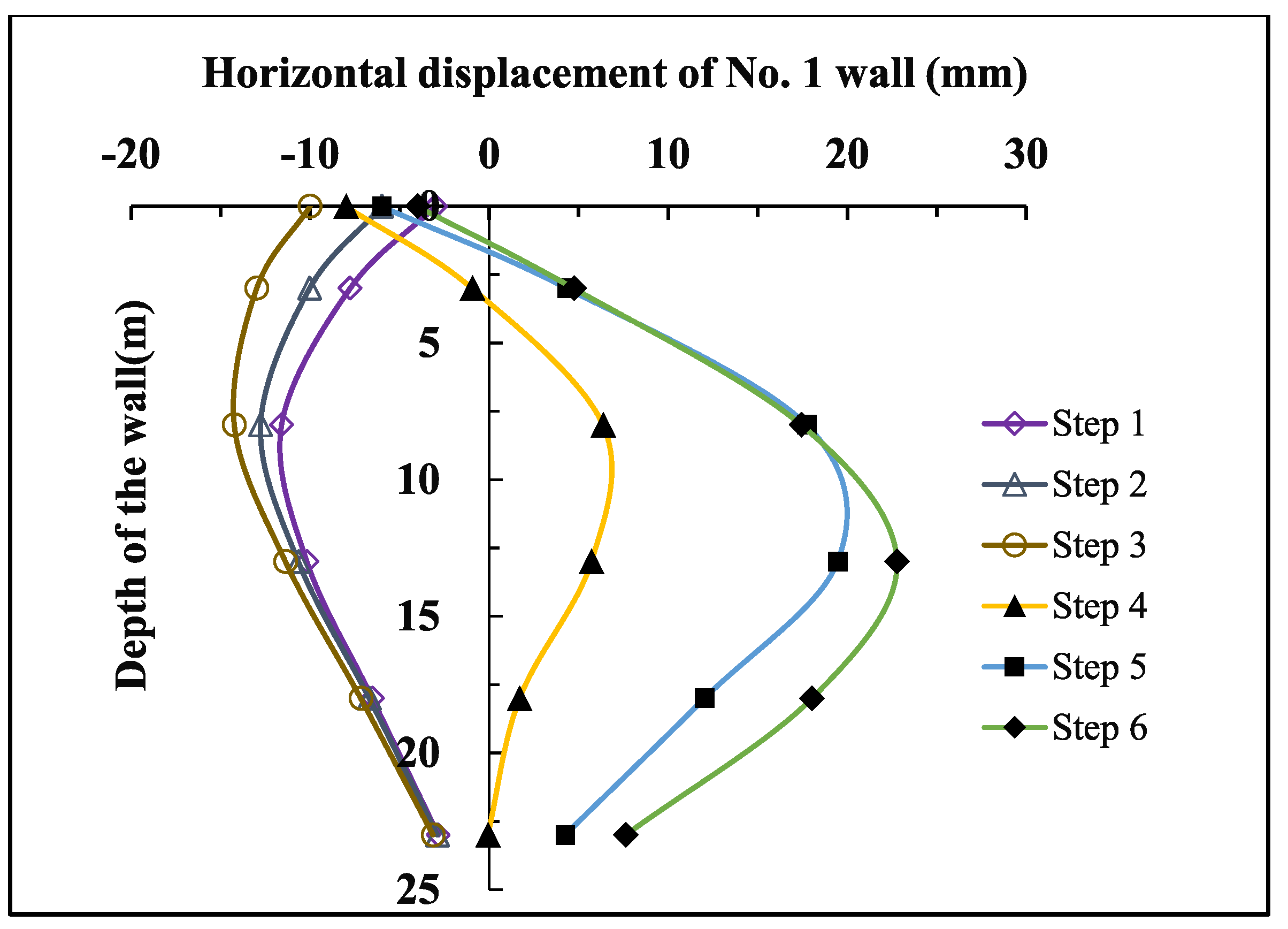
Figure 5 and Figure 6 show the bending moment and displacement of the No. 1 diaphragm wall under each construction step. The positive value in Figure 6 represents the inward displacement into the foundation pit excavated later. As shown in Figure 5, the bending moment of wall No. 1 gradually increased with the proceeding of the excavation from step 1 to step 3, which is consistent with the deformation law of a single foundation pit [2,3,5]. In excavation steps 4–6, the bending moment gradually increased. In construction steps 1–3, the position of the maximum bending moment changed little. In construction steps 4–6, the position of the maximum bending moment moved downward with increasing excavation depth. As shown in Figure 6, the displacement of diaphragm wall No. 1 was negative in excavation steps 1–3 and gradually decreased. In construction steps 4–6, the displacement increased gradually, and the maximum value increased with increasing excavation depth, but the wall top displacement was negative. The maximum positive bending moment of ground wall No. 1 throughout the excavation process was 305 kN.m. The maximum negative bending moment was −152 kN.m. The maximum positive displacement was 23 mm, and the maximum negative displacement was −14 mm. On the basis of these stress and deformation trends, the foundation pit constructed later and the ground wall adjacent to the first constructed foundation pit experienced a large negative bending moment during the construction of the first constructed foundation pit. This was mainly caused by the external unloading of the foundation pit excavated later induced by the excavation of the foundation pit constructed first. In addition, the wall top deformed toward the first foundation pit throughout the construction process, which should be considered in practical engineering, particularly when there are municipal pipelines between the two foundation pits.
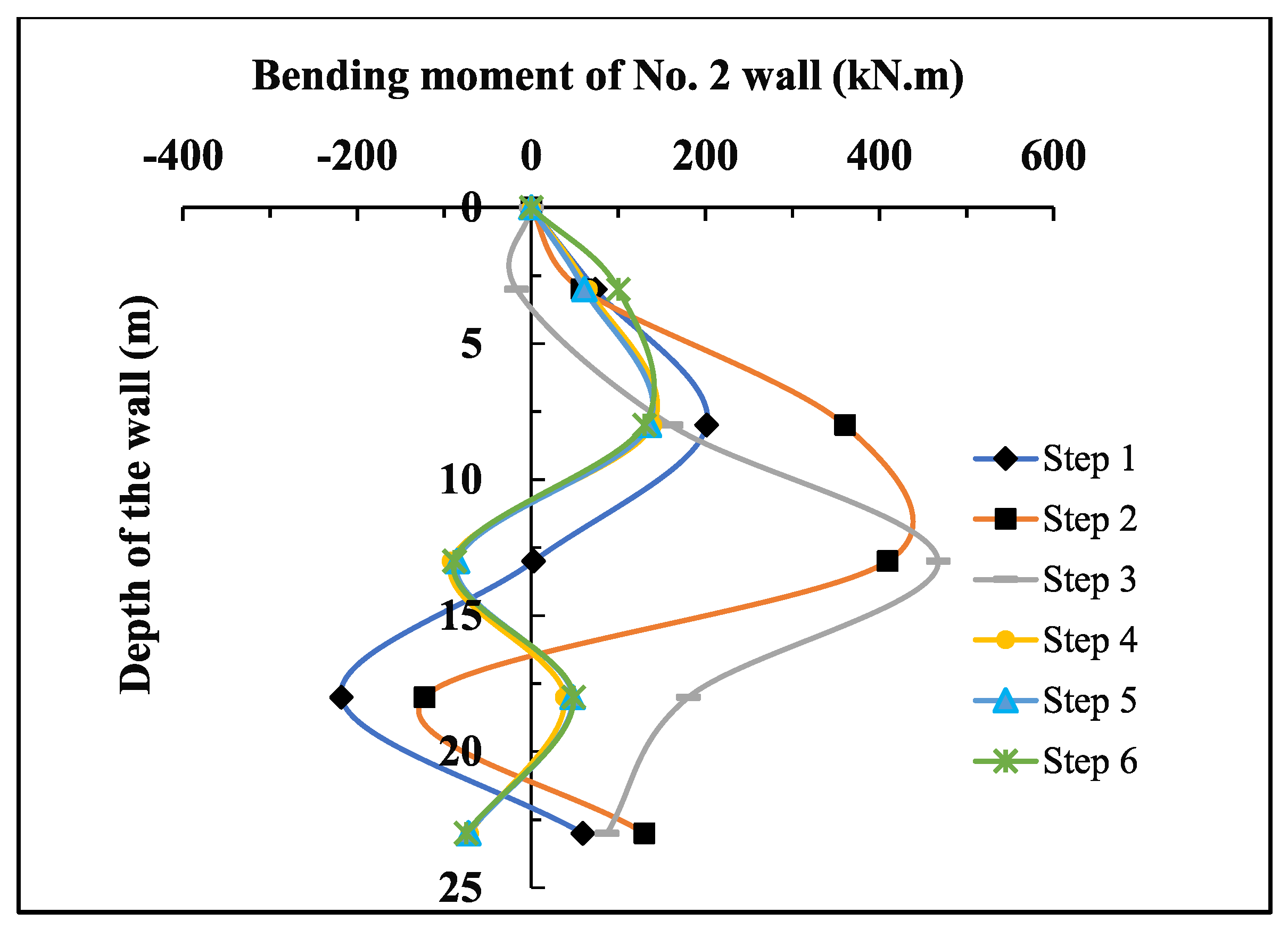
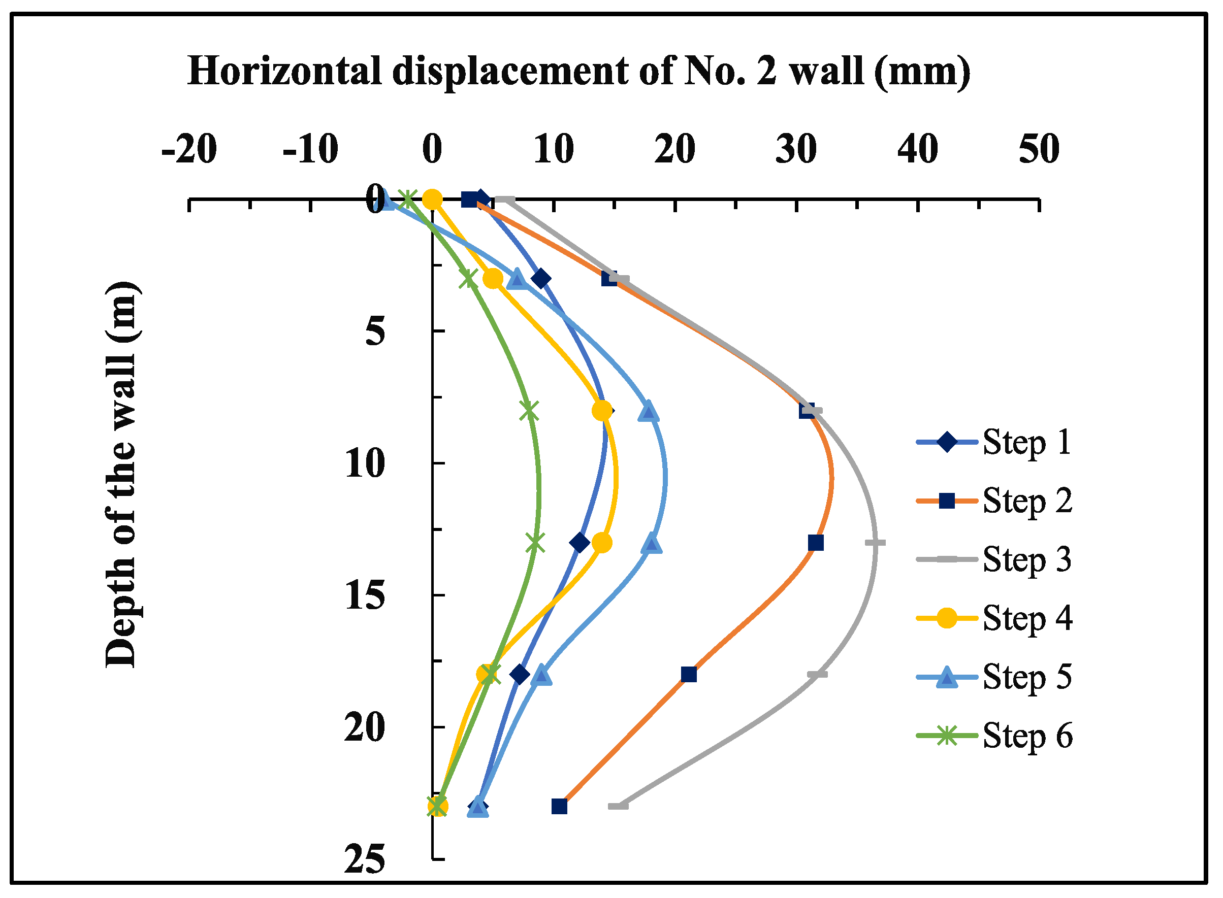
Figure 7 and Figure 8 show the bending moment and shear force diagrams of diaphragm wall No. 2 in each construction step, respectively. As shown in Figure 7, in construction steps 1–3, the bending moment curve of wall 2 moved toward the direction inside the pit, the maximum bending moment moved downward with increasing excavation depth, and the maximum moment was near the excavation surface. In construction steps 4–6, the bending moment of ground wall No. 2 changed slightly at different depths, indicating that the excavation of the later construction foundation pit has a relatively small impact on the stress of the first foundation pit. Figure 8 shows that in excavation steps 1–3, the maximum displacement of diaphragm wall No. 2 increased with increasing excavation depth. The maximum deformation under each working condition occurred near the excavation surface, and the final maximum displacement occurred near the pit bottom. Compared with that in the first three working conditions, the deformation of diaphragm wall No. 2 was smaller in construction steps 4–6. In excavation steps 1–3, the top displacement of the No. 2 diaphragm wall was positive, and in construction steps 4–6, the top displacement of the diaphragm wall was negative, indicating that the excavation of the later construction foundation pit still had a certain impact on the deformation of the first construction, and corresponding measures should be taken in the design of similar projects. In construction steps 1–3, the maximum positive bending moment of diaphragm wall No. 2 was 467 kN.m. The maximum negative bending moment was −218 kN.m, which was 1.43 times that of the postconstruction foundation pit. The maximum positive displacement was 36.5 mm, which was 1.59 times that of the postconstruction foundation pit. The maximum negative displacement was −4.0 mm, which was 0.29 times that of the postconstruction foundation pit. Thus, the stress and deformation of the foundation pit constructed first were larger than those of the foundation pit constructed later.
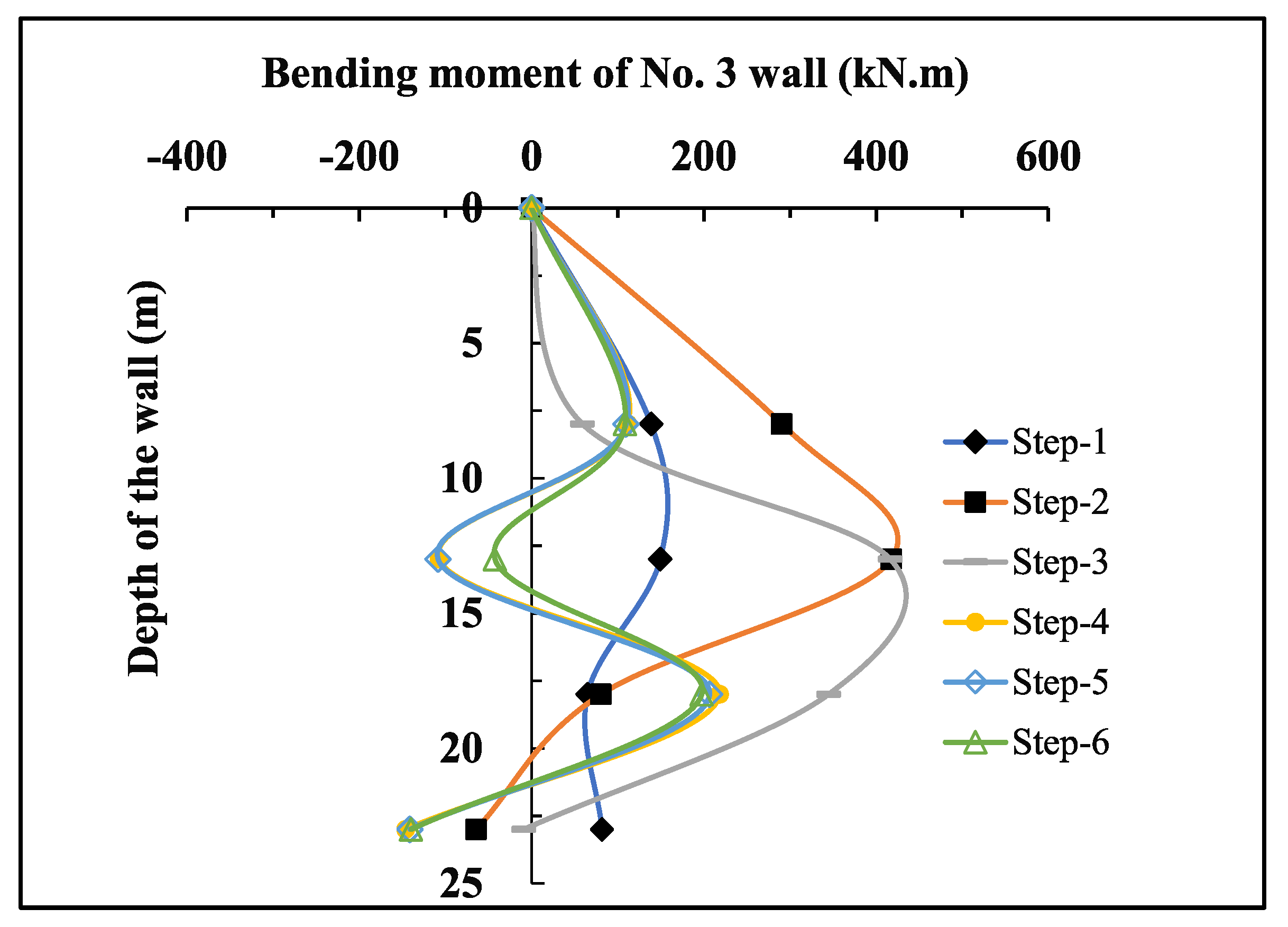
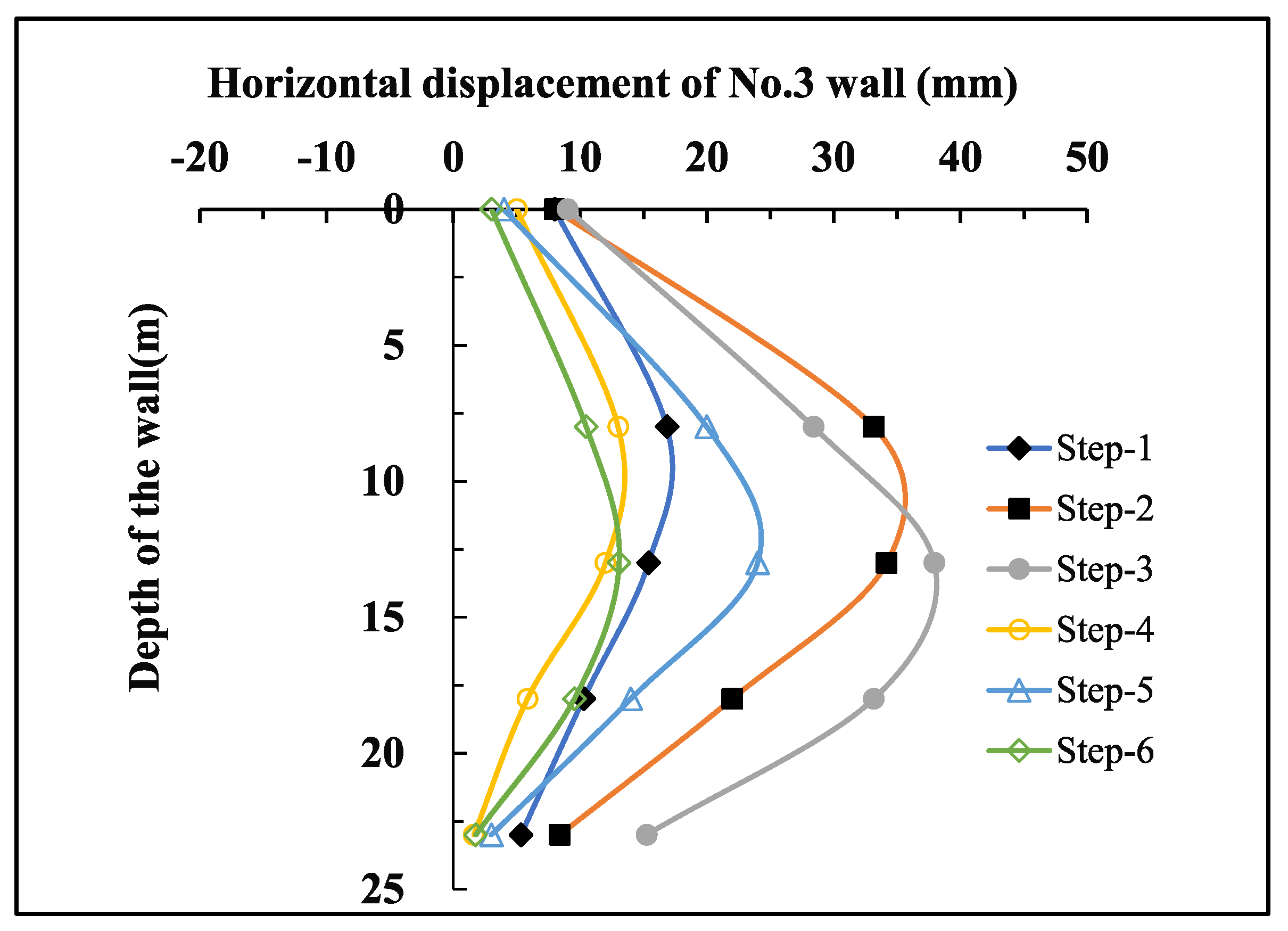
The strain gauge at the 3 m depth of diaphragm wall No. 3 was damaged during model installation and thus produced no measurements. In addition, no laser displacement meter was installed on the top of diaphragm wall No. 3, and the displacement of the top of the wall was obtained by fitting the trend line. The bending moment and displacement of wall 3 are shown in Figure 9 and Figure 10, respectively. As shown in Figure 9, in construction steps 1–3, the bending moment of diaphragm wall No. 3 generally increased with increasing excavation depth, but the position of the maximum bending moment moved downward in construction step 1. In construction steps 4–6, the bending moment of diaphragm wall No. 3 was small, and the change was small when excavating the adjacent pits. The displacement variation law of diaphragm wall No. 3 was similar to that of diaphragm wall No. 2, but the top displacement was positive in construction steps 4–6. Because no measuring points were arranged on the far end diaphragm wall of the foundation pit constructed later, it could not be compared to diaphragm wall No. 3. The bending moment and displacement of diaphragm wall No. 3 were generally larger than those of wall No. 2, and the displacement of diaphragm wall No. 3 in each construction step was greater than that of diaphragm wall No. 2. Therefore, the entire foundation pit constructed first was likely offset toward the middle.
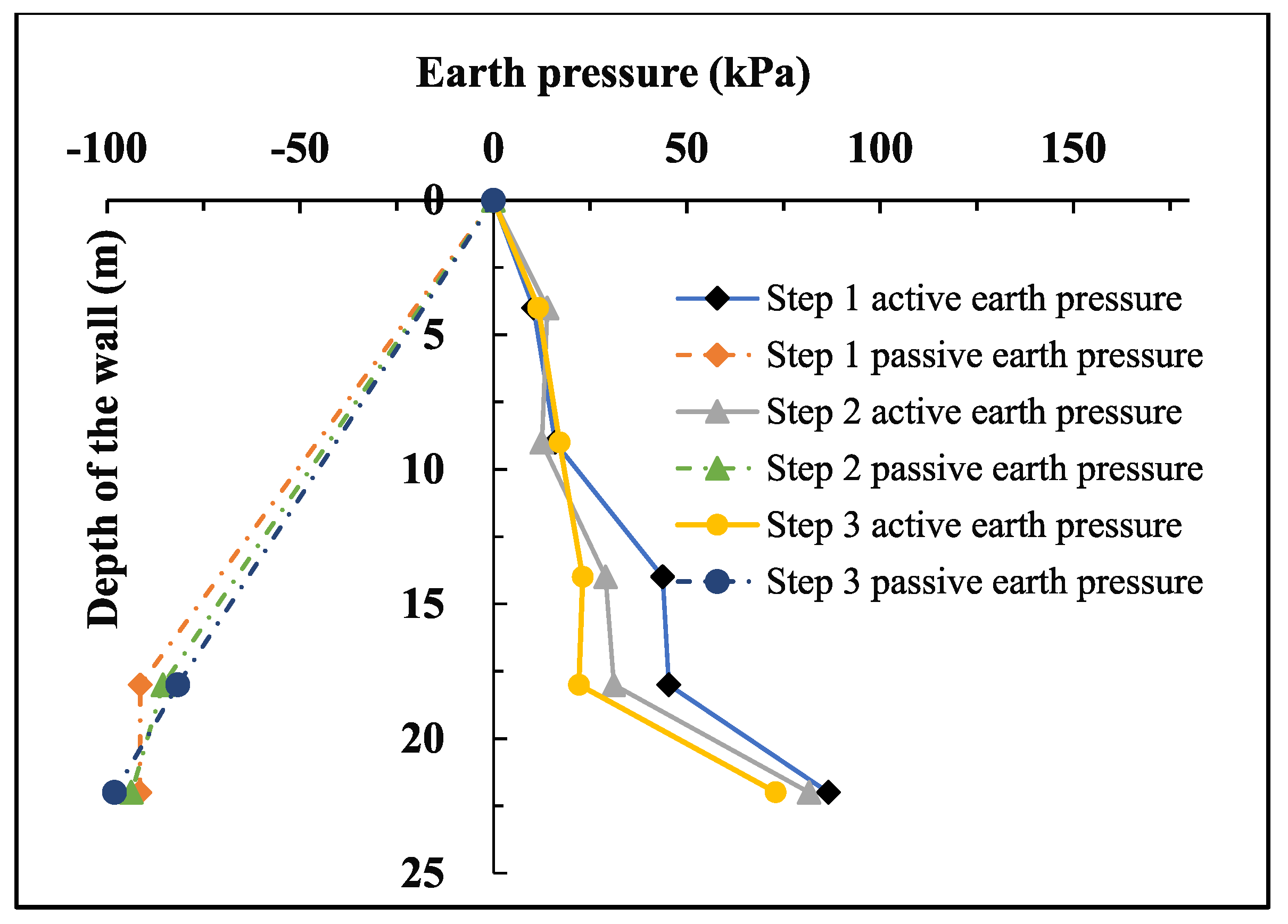
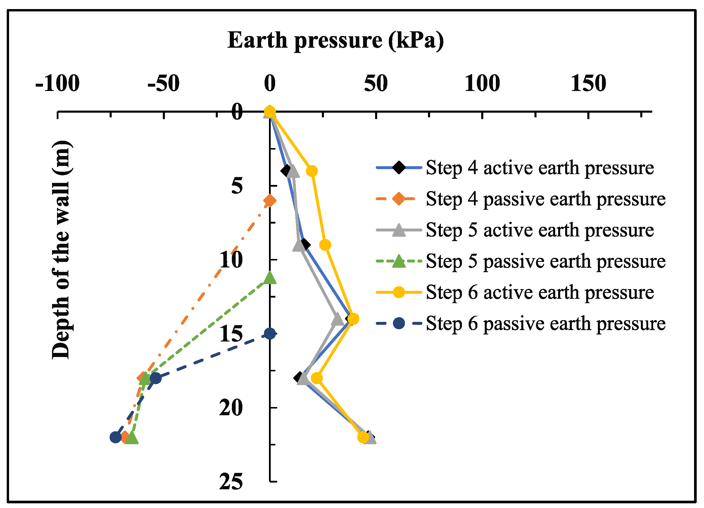
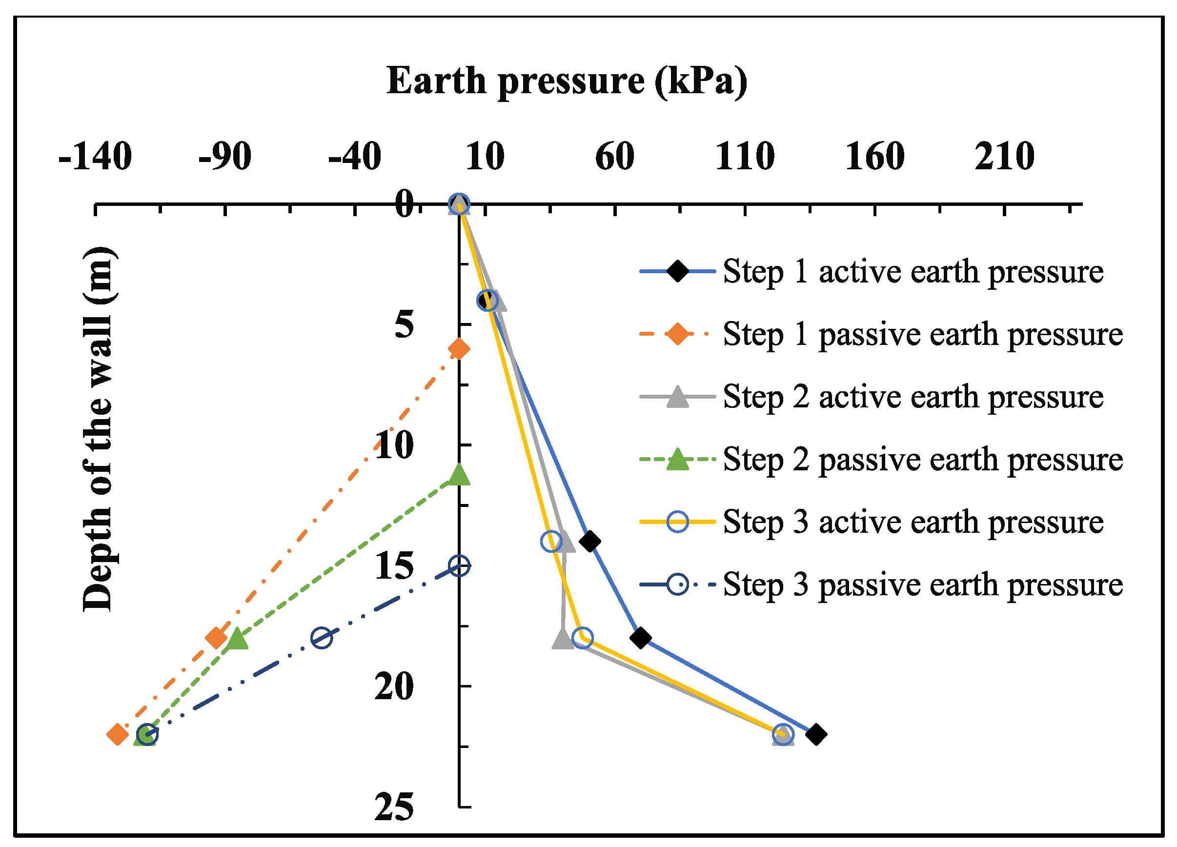
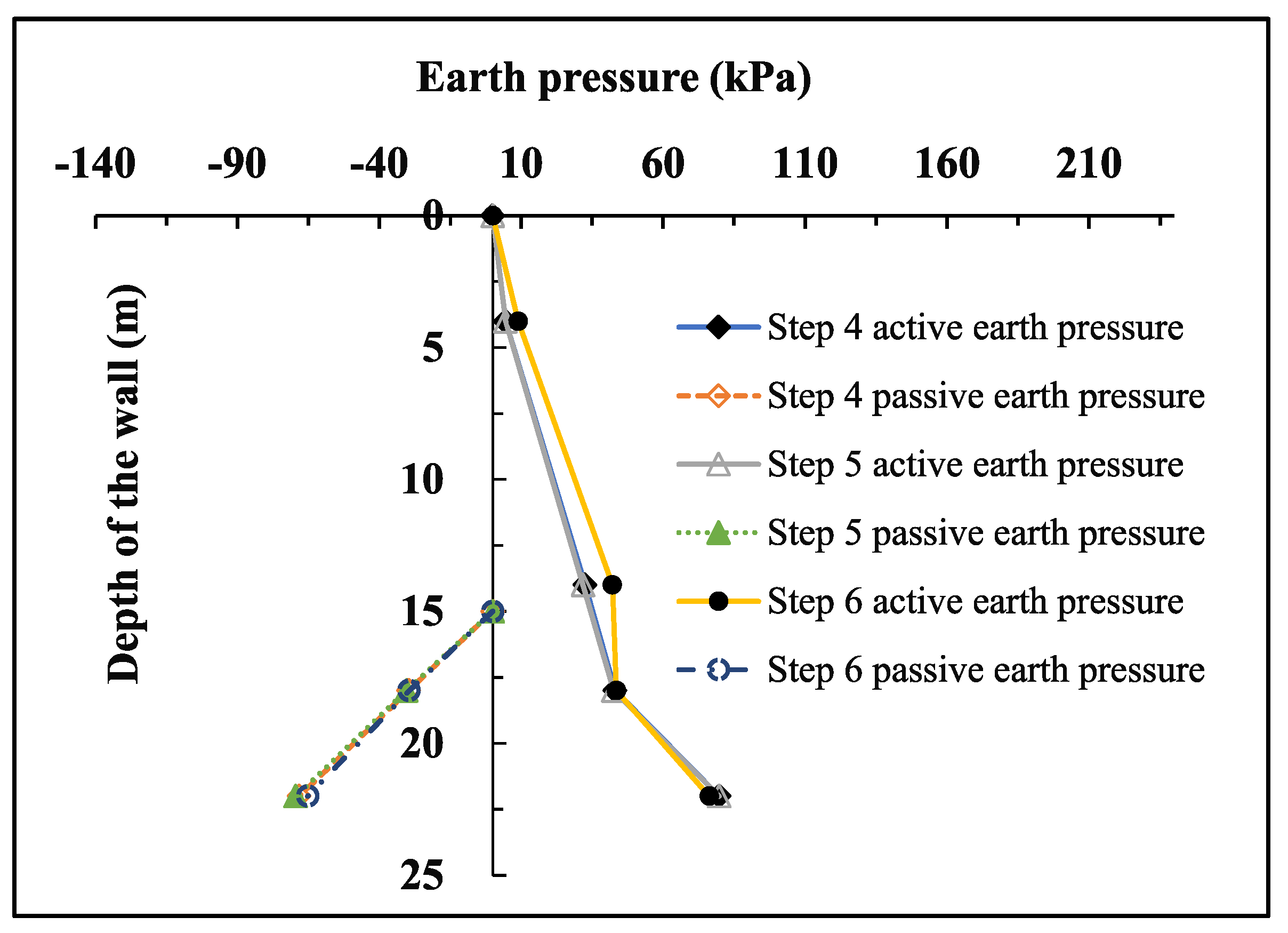
Figure 11 and Figure 12 show the variations in earth pressure on both sides of diaphragm wall 1 with each excavation step, respectively. Figure 11 shows that in construction steps 1–3, the active earth pressure outside diaphragm wall No. 1 decreased with an increasing excavation depth of the foundation pit constructed first and showed a roughly opposite trend in construction steps 4–6. The active earth pressure of diaphragm wall No. 1 in construction steps 1–3 was greater than that in construction steps 1–4, which was consistent with the deformation of the diaphragm wall throughout the construction process [26,28,29]. Because there were few passive earth pressure measuring points in the pit, the earth pressure was likely linearly distributed from the excavation surface to the measuring points. The figure also shows that the passive earth pressure on both sides of diaphragm wall No. 1 decreased with increasing excavation depth above 18 m.
Figure 13 and Figure 14 show the distribution of earth pressure on both sides of diaphragm wall No. 2 in each construction step, respectively. The earth pressure gauge of diaphragm wall No. 2 was damaged at a depth of 9 m, and thus, the distribution between 4 m and 14 m was assumed to be linear. The figure shows that in construction steps 1–3, the active earth pressure and passive earth pressure decreased with an increasing excavation depth for the first foundation pit. In construction steps 4–6, the active earth pressure and passive earth pressure remained relatively constant due to the relatively constant deformation of the ground wall.
Table 4 shows the axial force of two adjacent foundation pit supports in each construction step. Table 4 shows that the variation pattern of the axial force at measuring points ZC-1, ZC-2, and ZC-3 in step 1 and step 2 was consistent with that of a single foundation pit excavation [8,9,10]. Compared with ZC-3 and ZC-4, the axial forces of ZC-5 and ZC-6 were much smaller. On the basis of this comparison, the axial force of the support of the later excavated foundation pit was markedly smaller than that of the first excavated foundation pit. ZC-4 was under tension in the process of foundation pit excavation in the previous construction and increased with increasing foundation pit excavation depth. Generally, a support is not allowed to be under tension in foundation pit engineering, and this should be considered in engineering design. The deformation of the retaining system and surrounding strata during excavation is critical to ensure the safety of the foundation pit.
Table 5 shows that in construction steps 1–3, the soil settlement between two adjacent foundation pits gradually increased with the excavation of foundation pit B, and in construction steps 4–6, the settlement of intermediate soil gradually increased with the excavation of foundation pit A. The settlement of the middle soil in steps 1–3 was markedly larger than that in steps 4–6, indicating that the settlement of the middle soil exhibited strong superposition due to the influence of adjacent foundation pits.
4. Conclusions
Using centrifuge model tests, this study investigated the interaction between two adjacent foundation pits during the successive excavation. By analyzing centrifuge test results, the stress and deformation characteristics of two adjacent foundation pits, the earth pressure distribution of the middle adjacent retaining wall, the stress characteristics of the support, and the trends of ground settlement between adjacent foundation pits were described. The specific conclusions of this study are as follows:
- During the construction of foundation pit B, diaphragm wall No. 1 experienced a negative bending moment, the support experienced tension, and the wall top deformed toward the middle. Corresponding measures should be taken in real projects to avoid tension in support members.
- The stress and deformation of the retaining wall as well as the axial force of the support of foundation pit B were markedly larger than those of foundation pit A. Therefore, for similar practical projects, a foundation pit with high protection requirements should be constructed later.
- The active earth pressure of the middle soil of diaphragm wall No. 1 during the construction of foundation pit A was higher than that of diaphragm wall No. 2 during the construction of foundation pit B.
- The settlement of the middle soil in the construction of foundation pit B was larger than that in the construction of foundation pit A, indicating that the settlement of the middle soil was superimposed during the construction of two adjacent foundation pits.
- During the construction of two adjacent foundation pits, the displacement of wall 3 was greater than that of wall 2, indicating that during the construction of two adjacent foundation pits, foundation pit B was offset toward foundation pit A, but only slightly.
Author Contributions
Conceptualization, S.C. and F.L.; methodology, J.C.; software, S.C.; formal analysis, F.L.; investigation, J.C.; resources, S.C.; data curation, S.C.; writing—original draft preparation, J.C. and S.C.; writing—review and editing, F.L. All authors have read and agreed to the published version of the manuscript.
Funding
This research received no external funding.
Institutional Review Board Statement
Not applicable.
Informed Consent Statement
Not applicable.
Data Availability Statement
The data are contained within the article.
Acknowledgments
The authors wish to express their gratitude to the anonymous reviewers whose constructive comments helped improve the overall quality of the paper.
Conflicts of Interest
The authors declare no conflict of interest.
References
- Dan, K.; Sahu, R.B. Estimation of Ground Movement and Wall Deflection in Braced Excavation by Minimum Potential Energy Approach. Int. J. Géoméch. 2018, 18, 04018068. [Google Scholar] [CrossRef]
- Tan, Y.; Wang, D. Characteristics of a Large-Scale Deep Foundation Pit Excavated by the Central-Island Technique in Shanghai Soft Clay. I: Bottom-Up Construction of the Central Cylindrical Shaft. J. Geotech. Geoenviron. Eng. 2013, 139, 1875–1893. [Google Scholar] [CrossRef]
- Tan, Y.; Wang, D. Characteristics of a Large-Scale Deep Foundation Pit Excavated by the Central-Island Technique in Shanghai Soft Clay. II: Top-Down Construction of the Peripheral Rectangular Pit. J. Geotech. Geoenviron. Eng. 2013, 139, 1894–1910. [Google Scholar] [CrossRef]
- Chowdhury, S.S. Effect of location of surcharge on braced excavation under different excavation widths. In Proceedings of the Indian Geotechnical Conference 2012, New Delhi, India, 13–15 December 2012. [Google Scholar]
- Liu, Y.; Xiang, B.H.; Fu, M.F. Observed Performance of a Large-Scale Deep Triangular Excavation in Shanghai Soft Clays. Geotech. Geol. Eng. 2019, 37, 2791–2809. [Google Scholar] [CrossRef]
- Liu, Y.; Xiang, B.H.; Fu, M.F. Influence of Dewatering in Deep Excavation on Adjacent Pile Considering Water Insulation Effect of Retaining Structures. Geotech. Geol. Eng. 2019, 37, 5123–5130. [Google Scholar] [CrossRef]
- Lim, A.; Ou, C.Y. Stress paths in deep excavations under undrained conditions and its influence on deformation analysis. Tunn. Undergr. Space Technol. 2017, 63, 118–132. [Google Scholar] [CrossRef]
- Tan, Y.; Wei, B.; Zhou, X.; Diao, Y. Lessons learned from construction of Shanghai metro stations: Importance of quick excavation, promptly propping, timely casting and segmented construction. J. Perform. Constr. Facil. 2015, 29, 04014096. [Google Scholar] [CrossRef]
- Yan, G.; Wu, W.; Zhang, G. Centrifuge model test study of behavior of foundation pit. In Proceedings of the Geo-Shanghai, Shanghai, China, 26–28 May 2014; pp. 622–632. [Google Scholar]
- Tan, Y.; Li, X.; Kang, Z.; Liu, J.; Zhu, Y. Zoned Excavation of an Oversized Pit Close to an Existing Metro Line in Stiff Clay: Case Study. J. Perform. Constr. Facil. 2015, 29, 04014158. [Google Scholar] [CrossRef]
- Finno, R.J.; Arboleda-Monsalve, L.G.; Sarabia, F. Observed Performance of the One Museum Park West Excavation. J. Geotech. Geoenviron. Eng. 2015, 141, 04014078. [Google Scholar] [CrossRef]
- Ding, J.S.; Xian, Y.Q.; Liu, T.J. Numerical Modeling of Affection of Foundation Pit Excavation on Metro Tunnel. Adv. Mater. Res. 2012, 368–373, 2562–2566. [Google Scholar] [CrossRef]
- Liang, Y.Y.; Liu, N.W.; Yu, F.; Gong, X.N.; Chen, Y.T. Prediction of Response of Existing Building Piles to Adjacent Deep Excavation in Soft Clay. Adv. Civ. Eng. 2019, 2019, 8914708. [Google Scholar] [CrossRef] [Green Version]
- Chen, J.S.; Mo, H.H.; Liu, S.Z. Evaluation on Effect of Building Settlement due to Adjacent Deep Excavation. Appl. Mech. Mater. 2012, 170–173, 637–646. [Google Scholar] [CrossRef]
- Nazir, S. The effect of deep excavation-induced lateral soil movements on the behavior of strip footing supported on reinforced sand. J. Adv. Res. 2012, 3, 337–344. [Google Scholar]
- Zhang, H.B. Environmental Impact Induced by Excavation Group and Deformation Control. Ph.D. Thesis, Shanghai Jiao Tong University, Shanghai, China, 2016. (In Chinese). [Google Scholar]
- Wang, J.H.; Chen, J.J.; Li, M.G. Concept and characters of deep excavation groups in urban underground space development. Jpn. Geotech. Soc. Spec. Publ. 2016, 2, 1559–1562. [Google Scholar] [CrossRef] [Green Version]
- Chen, H.H.; Li, J.P.; Li, L. Performance of a zoned excavation by bottom-up technique in Shanghai soft soils. J. Geotech. Geoenviron. Eng. 2018, 144, 05018003. [Google Scholar] [CrossRef]
- Dai, B.; Hu, G.; Wang, H.S. Analysis and practice of influence of synchronous excavation of adjacent foundation pits in Shanghai area. Chin. J. Geotech. Eng. 2021, 43, 129–132. (In Chinese) [Google Scholar]
- Chen, D.J. Study on Excavation Displacement Transformation of Adjacent Pits in Shanghai South Railway Station. Buil. Sci. 2005, 21, 59–63. (In Chinese) [Google Scholar]
- Li, M.G. Deformation Behavior of Adjacent Retaining Walls in Group Excavation. Ph.D. Thesis, Shanghai Jiao Tong University, Shanghai, China, 2016. (In Chinese). [Google Scholar]
- Hu, M.Y.; Shou, S.D.; Yuan, J.; Zhang, Y.; Zhang, S.Z. Study on influence of excavation process of adjacent foundation pits. J. Zhejiang Univ. Technol. 2022, 50, 111–118. (In Chinese) [Google Scholar]
- Tao, D.J.; Zhang, H.W.; Kong, D.J. Interaction Effects Analysis of Twin Adjacent Excavations in Soft Soil Area. J. Water Resour. Archit. Eng. 2020, 18, 6. (In Chinese) [Google Scholar]
- Cui, J.F.; Li, J.P.; Li, L. Deformation of Subway Tunnels Affected by Adjacent Excavation: In-situ Monitoring and Centrifugal Model Test. In Proceedings of the GeoShanghai International Conference; Springer: Singapore, 2018; pp. 429–438. [Google Scholar]
- Guo, H.Q.; Tao, S.Z.; Zhang, Q. Research on Stress and Deformation of Super Deep Foundation Pits based on the Centrifugal Model Test. J. Undergr. Space Eng. 2020, 16, 177–186. (In Chinese) [Google Scholar]
- Xu, Q.W.; Ma, X.F.; Zhu, H.H.; Ding, W. Centrifugal model test on extra-deep foundation pit excavations in soft ground. China Civ. Eng. J. 2009, 12, 154–161. (In Chinese) [Google Scholar]
- Shao, P.; Zhu, C.; Pan, J.; Liu, N. Study on the Interaction of Limited Earth Pressure and Supporting Structure between Deep Foundation Pits. Chin. J. Undergr. Space Eng. 2021, 17, 187–195. (In Chinese) [Google Scholar]
- Li, L.X.; Fu, Q.H.; Huang, J.J. Centrifuge model tests on cantilever foundation pit engineering in sand ground and silty clay ground. Rock Soil Mech. 2018, 2, 529–536. (In Chinese) [Google Scholar]
- Liang, F.Y.; Chu, F.; Song, Z.; Li, Y.S. Centrifugal model test research on deformation behaviors of deep foundation pit adjacent to metro stations. Rock Soil Mech. 2012, 33, 657–664. (In Chinese) [Google Scholar]
- Chen, Y.M.; Tang, Y.; Ling, D.S.; Wang, Y.B. Hypergravity Experiments on Multiphase Media Evolution. Sci. China Technol. Sci. 2022. [Google Scholar] [CrossRef]
- Liang, F.; Liang, X.; Zhang, H.; Wang, C. Seismic response from centrifuge model tests of a scoured bridge with a pile-group foundation. J. Bridge Eng. 2020, 25, 04020054. [Google Scholar] [CrossRef]
- Liang, F.; Zhao, M.; Qin, C.; Jia, Y.; Wang, Z.; Yue, G. Centrifugal test of a road embankment built after new dredger fill on thick marine clay. Mar. Georesour. Geotechnol. 2020, 38, 114–121. [Google Scholar] [CrossRef]
- Xian-Feng, M.; Zhang, H.H.; Wei-Jie, Z. Centrifuge model tests on deformation of ultra-deep foundation pits in soft ground. Chin. J. Geotech. Eng. 2009, 31, 1371–1377. [Google Scholar]
Figure 1.
Layout plan of the model test.

Figure 2.
Model test section.

Figure 3.
Layout diagram of the strain gauge.

Figure 4.
Layout diagram of earth pressure cells.

Figure 5.
Bending moment of wall No. 1.

Figure 6.
Horizontal displacement of wall No. 1.

Figure 7.
Bending moment of wall No. 2.

Figure 8.
Horizontal displacement of wall No. 2.

Figure 9.
Bending moment of wall No. 3.

Figure 10.
Horizontal displacement of wall No. 3.

Figure 11.
Earth pressure distribution of No. 1 wall from Step 1 to Step 3.

Figure 12.
Earth pressure distribution of wall No. 1 from Step 4 to Step 6.

Figure 13.
Earth pressure distribution of wall No. 2 from Step 1 to Step 3.

Figure 14.
Earth pressure distribution of wall No. 2 from Step 4 to Step 6.


Table 1.
Basic physical and mechanical parameters of the soil layer.
| Soil Layer | Moisture Content/ω (%) | Internal Friction Angle/φ (°) | Unit Weight/γ0 (kN·m−3) | Compression Modulus/Es (MPa) |
|---|---|---|---|---|
| Standard sand | 4 | 31.0 | 16.1 | 11.3 |
Table 2.
Converted model size.
| Component Type | 1/n Ratio (Reinforced Concrete) | Alternative Materials (Aluminum Alloy) |
|---|---|---|
| Thickness of diaphragm wall model | 6 mm | 4.65 mm |
| Purlin size | 10 mm × 7 mm | 7 mm × 5 mm (solid) |
| Support section size | 8 mm × 7 mm | 7 mm × 4 mm (solid) |
| Support length | 200 mm | 200 mm |
Table 3.
Definition of each excavation step.
| Step | Event |
|---|---|
| Preparation | Excavation of Soil Layer 1 of foundation pit A and B, installing Strut 1 and Strut 4 |
| Step 1 | Excavation of Soil Layer 2 of foundation pit B and installing Strut 2 |
| Step 2 | Excavation of Soil Layer 3 of foundation pit B |
| Step 3 | Installing Strut 3 and excavation of Soil Layer 4 of foundation pit B |
| Preparation | Construction of the underground structure of foundation pit B |
| Step 4 | Excavation of Soil Layer 2 of foundation pit A |
| Step 5 | Installing Strut 5 and excavation of Soil Layer 3 of foundation pit A |
| Step 6 | Installing Strut 6 and excavation of Soil Layer 4 of foundation pit A |
Table 4.
Supporting axial force of each construction step (kN).
| Axial Force of Strut | ZC-1 | ZC-2 | ZC-3 | ZC-4 | ZC-5 | ZC-6 |
|---|---|---|---|---|---|---|
| Step 1 | 654 | 1798 | −198 | |||
| Step 2 | 476 | 3362 | −211 | |||
| Step 3 | 144 | 2657 | 4212 | −225 | ||
| Step 4 | 1130 | |||||
| Step 5 | 882 | 1382 | ||||
| Step 6 | 826 | 1250 | 2760 |
Table 5.
Surface subsidence of each construction step.
| Construction Steps | Step 1 | Step 2 | Step 3 | Step 4 | Step 5 | Step 6 |
|---|---|---|---|---|---|---|
| Surface subsidence (cm) | 9.6 | 10.4 | 10.9 | 5.3 | 6.6 | 6.9 |
Publisher’s Note: MDPI stays neutral with regard to jurisdictional claims in published maps and institutional affiliations. |
© 2022 by the authors. Licensee MDPI, Basel, Switzerland. This article is an open access article distributed under the terms and conditions of the Creative Commons Attribution (CC BY) license (https://creativecommons.org/licenses/by/4.0/).
Share and Cite
MDPI and ACS Style
Chen, S.; Cui, J.; Liang, F. Centrifuge Model Investigation of Interaction between Successively Constructed Foundation Pits. Appl. Sci. 2022, 12, 7975. https://0-doi-org.brum.beds.ac.uk/10.3390/app12167975
AMA Style
Chen S, Cui J, Liang F. Centrifuge Model Investigation of Interaction between Successively Constructed Foundation Pits. Applied Sciences. 2022; 12(16):7975. https://0-doi-org.brum.beds.ac.uk/10.3390/app12167975
Chicago/Turabian StyleChen, Shangrong, Jifei Cui, and Fayun Liang. 2022. "Centrifuge Model Investigation of Interaction between Successively Constructed Foundation Pits" Applied Sciences 12, no. 16: 7975. https://0-doi-org.brum.beds.ac.uk/10.3390/app12167975
Note that from the first issue of 2016, this journal uses article numbers instead of page numbers. See further details here.