Article

Comparative Study between Cost Functions of Genetic Algorithm Used in Direct Torque Control of a Doubly Fed Induction Motor

1
Industrial Technologies and Services Laboratory, Higher School of Technology, Sidi Mohamed Ben Abdellah University, Fez 30000, Morocco
2
Laboratory of Mechanical, Computer, Electronics and Telecommunications, Faculty of Sciences and Technology, Hassan First University, Settat 26000, Morocco
3
Electrical Engineering Department, Faculty of Engineering, Minia University, Minia 61111, Egypt
4
Engineering, Systems and Applications Laboratory, ENSA, Sidi Mohammed Ben Abdellah University, Fez 30000, Morocco
5
Laboratory of Systems Integration and Advanced, Faculty of Sciences Dhar El Mahraz, Sidi Mohamed Ben Abdellah University, Fez 30003, Morocco
6
Advanced Power and Energy Center, Department of Electrical and Computer Engineering, Khalifa University, Abu Dhabi P.O. Box 127788, United Arab Emirates
*
Author to whom correspondence should be addressed.
Submission received: 10 August 2022 / Revised: 22 August 2022 / Accepted: 25 August 2022 / Published: 30 August 2022
(This article belongs to the Collection Modeling, Design and Control of Electric Machines: Volume II)

Abstract

:
The proportional integral derivative (PID) regulator is the most often utilized controller in the industry due to its benefits. It permits linear systems to operate well, but it causes non-linear behavior when the system is subjected to physical variable circumstances, such as temperature and saturation. A PID controller is insufficient in this case. The proportional integral (PI) controller inside the direct torque control (DTC) regulates the speed of the doubly fed induction motor (DFIM). However, the system consisting of DTC and a DFIM is non-linear due to its multivariable parameters, resulting in undesirable overshoots and torque ripples. As a result, several approaches are used to improve the DTC’s robustness. The integration of optimization methods was discovered. These algorithms are used to provide gains that are near-optimal, bringing the system closer to its ideal state in order to accomplish effective torque and speed control. This article focuses on a comparative study of the different objective functions, in order to have very effective DFIM behaviors, by using a genetic algorithm. Agenetic algorithm (GA) is presented in this study for adjusting the optimal PID parameters in DTC to control the DFIM, utilizing objective functions such as integral square error (ISE), integral time absolute error (ITAE), and integral absolute error (IAE), employed independently and in a weighted combination. This article offers a comparison of several objective functions inside the DTC and DFIM, which will be utilized in future research into another optimization technique for this control type. Matlab/Simulink was used to construct the novel hybrid structure based on the GA-DTC intelligent control. The simulation results demonstrated the efficiency of the GA-DTC intelligent control with a weighted combination, providing acceptable performance with respect to rapidity, precision, and stability, as well as an improvement of 14.53% in the rejection time reduction, fewer torque ripples and flux ripples on the stator and rotor by 27.88%, 15.13%, and 4.375%, respectively, and respective increases of 32.45% and 71% in the THDs of the stator and rotor currents, which are acceptable.

1. Introduction

The development of new signal processing techniques paved the way for the creation of far more complex control structures. The DTC control approach was adopted in several studies [1,2,3,4]. The benefits of the DTC method (dynamics, robustness, high performance, and simplicity of implementation) are negatively influenced by the employment of hysteresis comparators. The comparators, in theory and practice, allow variable frequency as well as finite frequency sampling, allowing a speed response with pseudo-random overshoot [5,6]. As a result, the machine’s behavior is affected, particularly at low speed and during the variation of the machine parameters [7]. The harmonic content of the different output signals is difficult to anticipate due to these variables. In addition to that, applying the traditional DTC control on the DFIM generates significant torque oscillations, causing mechanical resonances and vibrations, as well as strong noise, leading to rapid machine aging [8].
The working principle of flux-oriented control (FOC) is to restore the DFIM’s behavior to that of a DC machine in order to maintain torque-flux decoupling [9,10,11]. However, under the scenario of direct flux-oriented control (DFOC) [11,12], this approach necessitates a sensor situated in the air gap for a direct detection of the flux, and the sensors are susceptible to mechanical damage (vibration, temperature, etc.) [12], and the indirect flux-oriented control (IFOC) eliminates the utilization of a flux sensor; however, the main drawback of this approach that the estimation is extremely sensitive to changes in the machine’s parameters, specifically the rotor and stator time constants. Thus, the control is regulated by six standard PID regulators, causing all of the system behaviors to be very sensitive to parametric variation.
Many academics have recently proposed artificial intelligence-based methods for improving the performance of conventional DTC (e.g., neural networks and fuzzy logic) and combined controls, not mandating information on the mathematical model. For responding to parametric changes, these methods are based on chance.
The authors of [13] recommended employing artificial intelligence approaches to enhance the dynamic performance of direct torque control. Direct neural torque control (DTNC), direct torque fuzzy control (DTFC), and direct neural fuzzy torque control (DTNFC) are some of the terms used to describe them, and they utilize artificial neural networks and fuzzy logic to generate a voltage vector that can direct flux and torque toward their set points over a set time, replacing truth tables and hysteresis comparators with controllers based on artificial intelligence; these techniques have been very successful. These approaches, in the case of DTC, allow the adjustment of the switching frequency, which results in faster fluxes and torque responses with less distortion. However, the underlying structure of the DTC-based method is more complicated and requires a powerful computer, which are the major disadvantages of solutions based on artificial intelligence [14].
A modern DFIM control approach developed in [15] was used to reduce torque ripples by applying a genetic algorithm of DTC control to the stator and optimizing the PID speed controller’s parameters. A total of 12V and 5Hz were applied to the rotor as power sources. However, for such circumstances, the DFIM functions as an induction motor (IM). You cannot drive the DFIM at excessive speeds [16].
The analysis in this article focused on the optimization of PID gains by deploying a GA andthe execution of a hybrid GA-DTC control deployed to the DFIM in connection with the two voltage inverters, in order to profit from the whole range of speed fluctuations, reduce the inverters’ joule losses, and address the difficulties stated above [17,18]. The finest advantages indicated at the start of this paragraph are found in this architecture. The GA optimizes the parameters KD, KI, and KP of the DTC’s PID speed controller. The major benefit of the GA formulation is that it may produce somewhat accurate results with a simple algorithm. Selection, crossover, and mutation are all iterative processes in the GA [19,20]. Parallel search strategies are used in a GA, and they are designed to mimic natural genetic processes. GAs have gotten a lot of interest in control systems, including searching for the optimal PID controller settings, because of their tremendous potential for optimization [21,22,23].
Several sorts of optimization issues have been solved using a genetic algorithm in the last 30 years. They cover a wide range of issues about not only communication network architecture, but also database query optimization and controlling the device [23]. Therefore, the GA has evolved into a dependable optimization approach for resolving issues in a variety of technological domains [24,25].
On the other hand, the research of [26,27,28] enables further robust PID in systems of anon-linear nature. These works employed particle swarm optimization (PSO) and grey wolf optimizer (GWO) algorithms to optimize the PID controller in the case of an adopted second-order DC motor system. In [29], a non-dominated sorting GA was deployed to tune the PID control, considering a multi-objective problem. The work considered a tune to be a robotic manipulator. To tackle the restricted optimization problem in a servo motor system, reference [30] suggested a GA-based PID controller. When compared to PSO and evolutionary programming (EP), GA optimization was observed to yield extremely valuable results in relevance to overshoot, response time, and static error [31].
The gains of the PID speed controller were improved by GA, utilizing a weighted mixture of objective functions such as integral absolute error (IAE), integral time absolute error (ITAE), and integral square error (ISE) in comparison to the traditional DTC and a single goal function to illustrate the robustness of the suggested intelligent method. The Matlab/Simulink environment was used to assess this investigation.
The following objectives outline the potential improvements discussed in this article:
  • Torque and fluxes ripples are minimized to the greatest extent possible (hysteresis comparator, variability in the parameters of the machine, fluxes, torque estimators, and inverters).
  • Electromagnetic torque and speed performance are both improved.
  • The stator and rotor currents’ total harmonic distortion (THD) rate is reduced.
The axes used to organize this article are as follows: The mathematical model of the DFIM in the (alpha, beta) plane is covered in Section 2. The functionality of the DTC control and its core structure is covered in Section 3. The method for attaining optimized parameters of the PID speed controller is covered in Section 4. Section 5 provides the simulation results of the GA-DTC. The analysis of the findings and a suggestion for future study are covered in Section 6.

2. DFIM Model in (Alpha-Beta) Frame

The adequate model for establishing the controls applied to a rotating alternating machine is the two-phase model (alpha, beta) calculated by the Concordia transform, which allowed us to have a reduced and simple model expressed by the following expressions [17,18]:
  • Electrical equations:
    v s α = R s · i s α + d ψ s α d t v s β = R s · i s β + d ψ s β d t v r α = R r · i s α + d ψ r α d t + ω m · ψ r β v r β = R r · i r β + d ψ r β d t ω m · ψ r α
  • Magnetic equations:
    ψ s α = L s · i s α + L m · i r α ψ s β = L s · i s β + L m · i r β ψ r α = L r · i r α + L m · i s α ψ r β = L r · i r β + L m · i s β
  • Mechanical equations
    T e m = p · ψ s α i s β ψ s β i s α
    J d d t + f = T e m T r

3. DTC Modelling

The principle of DTC control is to generate pulses that will be applied directly to the inverter switches to generate frequency-variable currents depending on the reference speed. To do this, the rotor and stator fluxes and the motor torque must all remain within the defined hysteresis bands in order to avoid significant torque ripples. The use of this strategy ensures that the torque and flux are not coupled. The seven non-zero voltage vectors and one zero vector are represented on a 360° circle, which results in eight voltage vector sequences at the outputs of the inverters, which are activated as per to the states of the hysteresis comparators and the position of the voltage vectors. The voltage vectors are generated subsequently and applied to the motor armatures [1].
The working principle of this strategy lies in the regulation of the parameters of flux and torque without having direct measurements of these parameters by estimating the flux and torque and making a comparison with flux and torque references.
The fluxes in the fixed reference (α, β), are calculated using the following equations [5,6]:
ψ ¯ s α = V ¯ s α R s · I ¯ s α d t ψ ¯ s β = V ¯ s β R s · I ¯ s β d t
ψ ¯ r α = V ¯ r α R r · I ¯ r α d t ψ ¯ r β = V ¯ r β R r · I ¯ r β d t
The machine is powered by two voltage inverters controlled by Sa, Sb, and Sc, which are supplied with continuous voltages Udcs and Udcr, allowing them to generate voltages expressed by:
V α = U D C 3 2 · S a S b S c V β = 3 U D C 3 S b S c
In the DTC control, the stator and rotor fluxes are not measured, but are estimated, which are expressed by their modules and arguments, expressed as follows:
ψ = ψ α 2 + ψ β 2 θ = tan 1 ψ β ψ α
You may do it this way: it is possible to obtain the electromagnetic torque from the following expression:
T ¯ e m = p ψ ¯ s α · i s β + ψ ¯ s β · i s α

3.1. Fluxes and Torque Correctors

Fluxes are sustained in a circular crown, as demonstrated in Figure 1a. This function is carried out by two two-level hysteresis comparators Figure 1c. A three-level hysteresis comparator is responsible for controlling the motor’s electromagnetic torque in a clockwise direction and counterclockwise direction, enabling the generation of positive/negative torque. An example of a three-level hysteresis torque comparator is presented in Figure 1b.

3.2. Elaboration of the Switching Table

The vs. and Vr voltage vectors can be employed and selected according to the torque and flux references, depending on the industry and the evolution of the torque and fluxes. Using Table 1, which focuses on flux errors ΔΨs and ΔΨr, torque errors ΔTem, and flux vector locations (i = 1, 2, 3, 4, 5, and 6), the suitable vectors may be selected to regulate the fluxes and electromagnetic torque of a doubly fed induction motor [9].

4. Working Principal of Genetic Algorithm for PID Parameter Optimization

Genetic algorithms (GA) are a type of research method for balancing the maximization of research space and the maximization of the use of the best results. Genetic algorithms, according to theoretical analyses [16], are the best way to control this compromise.The speed is controlled by a PID controller in a traditional DTC control that is of undesired overshoots, as well as static errors, in non-linear systems. However, this case cannot be addressed by the DTC’s inadequacies. The GA’s optimization of the parameters KP, KI, and KD allows for the creation of ideal PID controller values at each sample time that are tailored to the system’s non-linearity [32,33]. The GA optimization approach is described by Figure 2, with its simplified structure.
Selection, crossover, and mutation are essential steps of GAs, which belong to evolutionary algorithms that are based on techniques inspired by evolutionary biology. Genetic algorithms are a subset of evolutionary algorithms that apply techniques stimulated by evolutionary biology. This is illustrated in Algorithm 1, which is a flowchart following the evolution principles of a genetic algorithm and depicts the sequences of operations that take place in a genetic algorithm.
The following are the steps for implementing the GA:
Algorithm 1: Genetic Algorithm
Begin
Step 1. Make the initialization of algorithm parameters (Sigma, Iter, Gamma, Pc, Pop, nVar, Pm, VarMin, and VarMax).
Step 2. Consider generating the parameters for the PID controller in a random fashion.
Step 3. Run the DTC automatically.
Step 4. Measure the fitness function.
Step 5. Make binary coding.
Step 6. Make the selection step.
Step 7. Make the crossover step.
Step 8. Make the mutation step.
Step 9. Focus on generating the optimum values of KD, KI, and KP.
Step 10. Consider repeating step number 3 until the maximum Iter is complete.
Step 11. Save and print the optimum solutions.
End
The synoptic structure in Figure 3 represents the new proposed GA-DTC approach implemented on both sides of the DFIM.

4.1. GA Operators and Parameters

Operators are crucial to a GA’s potential success. The selection, crossing, and mutation operators are the three main ones. Although the fundamentals of each of these operators are simple to comprehend, it can be challenging to convey the individual significance of each operator to the GA’s performance. This is partly because each of these operators acts in accordance with different criteria that are unique to it (selective value of the individuals, probability of activation of the operator, etc.).

4.2. Chromosome Coding

This algorithm begins with a binary coding of solutions in the form of chromosomes, defined as a group of genes or bits in the logical foundation [24]. GAs use coding techniques, which is their key distinction from other search optimization strategies. In most cases, a GA employs binary coding [34,35]. Since it depends on the situation, it is impossible to declare which coding approach is best. Real numbers are simpler to utilize, but only for a particular issue. It is necessary to specify the PID controller’s performance limits before calculating its coefficients. The method developed establishes the lowerboundary for zero PID coefficients. In order to solve an encoding issue, a GA cannot act alone. Therefore, the GA results are impacted by an improper encoding format. According to this work, each PID parameter was treated as a gene and was encoded as a separate chromosome [36,37].

4.3. Fitness

The selection of the objective functions considered to assess each chromosome’s appropriateness is a crucial phase in GA implementation. Performance indices were employed in several publications [38,39] as objective functions. While using ISE, IAE, and ITAE in [18], the authors of [40] utilizedmean squared error (MSE), integral time absolute error (ITAE), integral absolute error (IAE), and integral square error (ISE). In this work, the speed error signal e(t) = Ωref(t) − Ω(t) was minimized and compared using the performance indices IAE, ITAE, and ISE, as well as a combination of the three indices, to determine which was most appropriate. The following description of the performance indices is required [41,42]:
I A E = 0 t e t d t
I S E = 0 t e t 2 d t
I T A E = 0 t t · e t d t
F w = ω 1 × I A E + ω 2 × I S E + ω 3 × I T A E
where Fw is the weighted function, e(t) is the error signal, and ω1, ω2, and ω3 are the weights.
The genetic algorithm was used in this work for minimizing the error among the reference and the real speed of the motor. This operation is carried out by increasing the fitness value represented by the expression 14, which automatically reduces the error. For each iteration of the regulator, gains are generated in such a way as to maximize the fitness. The gains that allow to have a very low error are considered optimal solutions [43].
Fitness _ Value = 1 Objecitves _ Functions

4.4. Initialization of Populations

Once the coding is chosen, an initial population made up of admissible solutions to the problem must be determined. Several mechanisms for generating the initial population have been used in the literature [44,45]. The choice of initialization is made according to the knowledge that the user has about the problem. If they have no particular information, then a random initialization, as uniform as possible in order to favor an exploration of the maximum search space, is the most suitable. However, in other cases, it is possible to use other mechanisms. Moreover, this step presents a main problem, which is that of the choice of the size of the population. A population that is too large increases the computation time and requires considerable memory space, while a population that is too small leads to obtaining a local optimum. Grefenstette claimed that a population size of between 10 and 160 is ideal for the genetic algorithm. However, the study also demonstrated that the odds of crossover, mutation, and population size have non-linear connections. For classification issues, Odeyato recommended a range of 100–400, whereas Robertson utilized sizes up to 8000. In a different study, Goldberg examined the ideal population size for sequential and parallel genetic algorithms. The choice of the initial population of people has a significant impact on how quickly the algorithm runs. In this study, the best population size used was 20 individuals, found after many experiments, which proved its efficiency.

4.5. Selection Operator

An intermediate population to the population of the current generation ’i’ is formed at each generation using the selection operator. After that, these populations are combined and altered to create the population of generation ‘i+1′. The chromosomes are chosen from the most adaptable people. There are numerous methods for selecting candidates, but we focused on the best-known ones:
  • The simplest one, known as “ranking”, consists of classifying the n chromosomes of the population by increasing the order of their respective evaluation (or decreasing the order, depending on the objective). The first m individuals are then selected. Thus, only the best individuals are kept.
  • Selection by roulette wheel: This consists of associating to each chromosome a segment whose length is proportional to its fitness. These segments are then concatenated on a graduated axis that is normalized between 0 and 1(uniform distribution between 0 and 1); then, we identify the selected segment and the corresponding chromosome. With this technique, good chromosomes are selected more often than bad ones, and the same chromosome can, with this method, be selected several times. Nevertheless, in small populations, it is difficult to obtain the exact mathematical expectation of the selection because of the small number of draws. The selection bias will be more or less strong depending on the size of the population.
  • Selection by tournament: this technique randomly draws two or more individuals from the population, and the strongest is selected, i.e., the one with the most interesting fitness.
  • Random selection: as its name indicates, this type of selection chooses the chromosome according to a uniform distribution.
In this study, we chose tournament selection, which is used most often by many authors [46,47].

4.6. Crossover Operator

Crossover allows two parents to mate to form two offspring. The idea is that the children keep the best characteristics of their parents. The principle of crossing consists of recombining the good parts of the chromosomes of the two parents, P1 and P2, to generate two children, E1 and E2, of better quality. For example, using binary representation, two strings, 00000000 and 11111111, could intersect at the fifth bit into each other to produce two new children, 11110000 and 00001111, respectively, of probability 0.5, which has half of the chromosome [48]. Crossover should be avoided by choosing a crossover probability between 0.6 and 0.99 [49]. In this study, the probability used was 0.8, chosen as the probability value of the crossover operator.

4.7. Mutation Operator

Figure 4 provides a flowchart that follows the GA’s evolutionary guidelines while describing the steps of operations considered in a GA. The algorithm expresses the GA execution process in the following steps. The mutation is responsible for preventing the algorithm from converging too fast to a local optimum, allowing us to explore the search space. The idea behind mutation is to alter one of these chromosomes in order to investigate a potentially more intriguing region of the search space. Although it gives genetic algorithms the virtue of ergodicity, mutation is traditionally thought of as a marginal operator (i.e., all points of the search space can be reached). Consequently, this operator is crucial. This quantity must lie within the interval [0.001, 0.01] [50,51] for mutation to contribute new information to the genetic chromosome and prevent the population from accelerating toward a local optimum in a particular environment. The setting of the probability Pm value was considered as 0.001 in the targeted study [51].

5. Simulation Approach and Considerations

Under the environment of MATLAB/Simulink, the PID controller based on a GA was used to simulate the DTC control of a DFIM, including ISE, IAE, and ITAE, separately and in a weighted combination, with the aim of finding optimal gains that meet the problem requirements. GA parameters (VarPmin, VarPmax, VarImin, VarImax, VarDmin, VarDmax, Pop, and niter) must be initialized to very large values at initialization (VarDmax = VarImax = VarPmax = 100, VarDmin = = VarImin = VarPmin− 100, Pop = 100, and niter = 100) to increase the possibility of optimal values for KP, Ki, and KD. However, in this case, the system’s convergence is attained only after a certainconsiderable amount of time, possibly reaching a few days, and from the optimal value, the range of change of these parameters may be reduced to a value near the optimal value, because the system would converge to the optimal valuesand then return from these values optimally, reducing the number of iterations, because the system converged toward its optimumtargets.As a result, the system can swiftly converge on the ideal answer. The GA-generated PID controller’s parameter values fell within the fluctuation range shown in Table 2. The settings in Table A1 and Table A2 in the Appendix A, were used to configure the system, and the system was then tested for reference speed and torque. On a 0.8 kW machine, the simulation results of the two techniques, standard DTC and GA-DTC, were examined and set up as follows:
  • Sampling time: fs = 0.0001 s.
  • Hysteresis bands: ΔΨr = ±0.001 Wb, ΔΨs = ±0.001 Wb, and ΔTem = ±0.01 Nm.
  • Nominal load (TL = 5 Nm) at t = 0.5s.

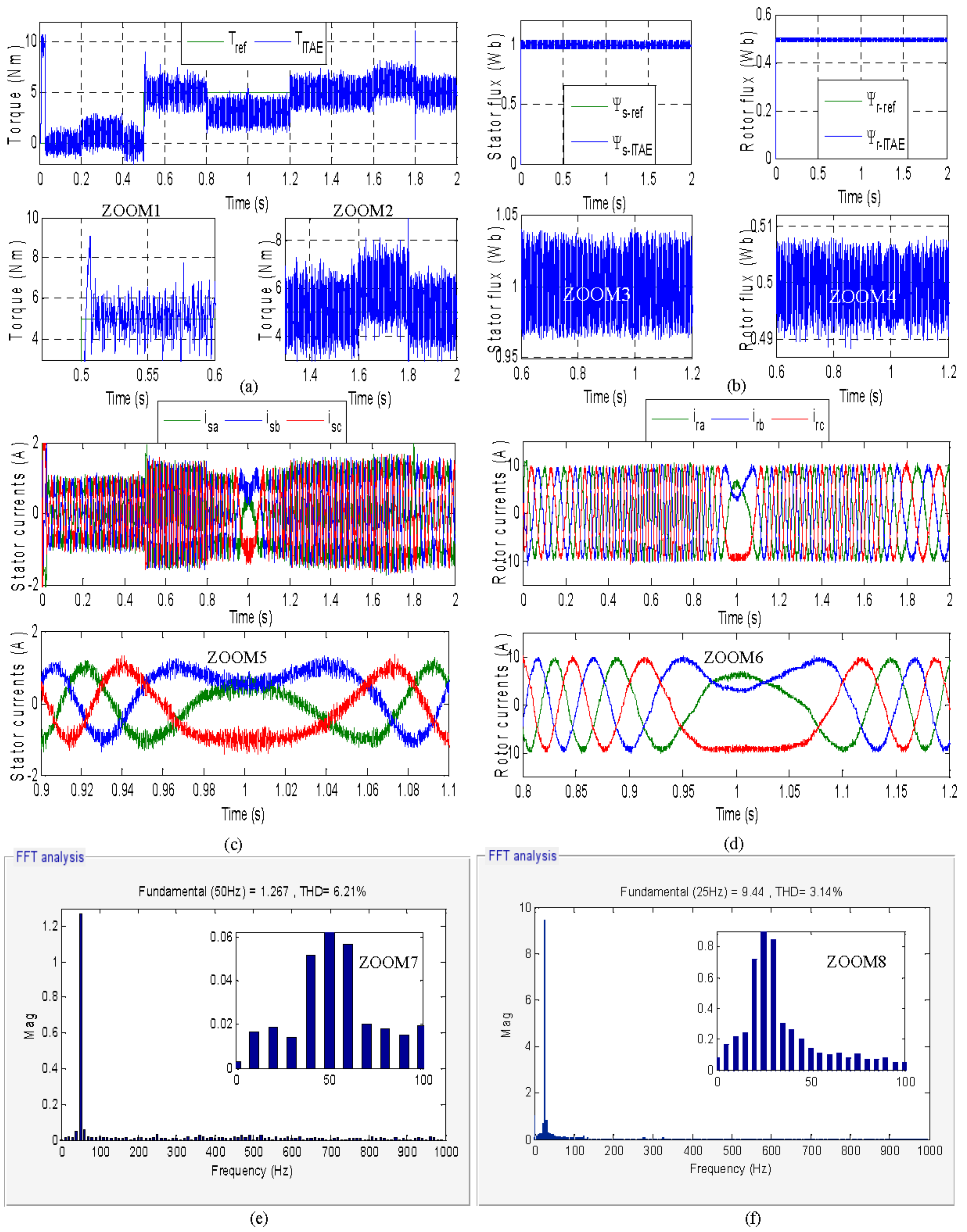
5.1. Simulation Results

After several simulations test, the GA by using objective functions used separately and with a combined association, the simulations results of the proposed approach are presented as follows (Figure 5, Figure 6, Figure 7, Figure 8, Figure 9 and Figure 10):

5.2. Interpretation

To evaluate the tracking capabilities of the conventional DTC and the suggested GA-DTC, optimized utilizing the ISE, IAE, and ITAE functions, independently, as well as the weighted combination of these three functions as objective functions, speed and torque setpoints were introduced.
The weighting factors associated with each of the combined objective functions were as follows: w3 = 04; w2 = 0.2; and w1 = 0.4. Therewas no analytical method to choose the weights of the weighted function; it was based on the principle of chance.Each time we proposed values and ran the simulation, we saved the results and modified the weights again, comparing the results of each weight and taking the weights that had the greatest impact on the results that were estimated as optimal weights; in our study, we proposed the weights mentioned above.
The responses in Figure 5 show that the controllers can train the MADA to follow the variability in the reference speed at no load and at load, as the set speed varied respectively in the range of [78.5 rad/s, 157 rad/s] and [−157 rad/s, −78.5 rad/s] during the progressive variation. It is quite remarkable that, as shown in Figure 5, the motor speed settled on the reference for the AG-CDC control withISE, IAE, and ITAEused separately and with weighted objective functions, and required less response time than the CDC control, especially the weighted AG-CDC control, with an improvement of 39.8% (40.2 ms for the classical CDC control and 40.2 ms for the weighted AG-CDC control).So, we sawthat the cancellation of the overshoot for the AG-CDC-ISE and weighted control registered a 100% reduction during the whole training phase, as well as a significant reduction of the undershoot by 6.25% (3.2 rad/s in terms of the conventional CDC control and 3 rad/s in terms of the weighted AG-CDC control); on the other hand, the rejection time necessary for the machine speed to reach its reference after the application of a load torque showed an improvement of 14.53% for the weighted control (1.17 ms for the conventional CDC control and 1 ms for the weighted AG-CDC control), which means an absolute adaptation of the speed to each disturbance.On the other hand, the different techniques showed good speed tracking throughout the reference, with a difference in response time and overshoot, finding that the GA-DTC-ISE control and a combined control allowed to have a perfect use of rotational speed, which proved the efficiency of the proposed control, especially with the ISE function and with a combination of objective functions. Table 3 shows the different performance measures of speed, torque, and flux ripples, as well as the THDs of the stator/rotor currents.
From Figure 6a, Figure 7a, Figure 8a, Figure 9a and Figure 10a can notice that the control proposed with the use of ISE, ITAE, and IAE, separately and combined, allowed to have a very acceptable follow-up profit, especially with a sudden variation of the load, which confirmed the effectiveness of the proposed strategies. However, the GA-DTC control function with ISE and with a combination of objective functions allowed for perfect tracking, with a reduction in significant ripples compared to the conventional CDC approach and compared to other objective functions, which showed improvements of 27.88% (3.591 Nm in the case of the conventional CDC control and 2.59 Nm in the case of the weighted AG-CDC control), so it can be said that the ISE and weighted approaches present a tracking of the reference setpoint without any underruns, as is shown in the conventional CDC approach. On the other hand, the torque behaviors at the start and at the sudden changes of speed were similar for all the control strategies, which is normal, because it is difficult or impossible to have a control that allows to completely cancel the call to the currents during the moments mentioned above. However, they are limited through a saturation block, which is the torque band that is chosen between +15 Nm and −15 Nm in order not to exceed the recommended starting torque.
Using a weighted combination, the stator and rotor flux waveforms for the proposed AG-CDC controls are demonstrated in Figure 6b, Figure 7b, Figure 8b, Figure 9b and Figure 10b. The combined objective functions exhibited a good dynamic range, and the latter resulted in a reduction of the stator and rotor ripples by 15.13% and 4.375%, respectively (0.0727 Wb and 0.016 Wb, respectively, in terms of the conventional CDC control, and 0.0617 Wb and 0.0153 Wb, respectively, in terms of the weighted AG-CDC control). Because of these characteristics, the AG is well-suited for high-performance applications.
Figure 6c,d, Figure 7c,d, Figure 8c,d, Figure 9c,d, and Figure 10c,d, illustrate the stator and rotor currents that are sinusoidal, with variable harmonics as a function of load variation, as well as the impact of the optimal gains of each strategy, using the weighted and separated objective functions. However, what interests us is the harmonic spectral analysis of the currents to measure the rate of harmonic distortion. It is well-known that the rates of THDs are the image of the torque ripples. With a high rate, further ripples would be created from the torque and vice versa. It can be observed in Figure 6e,f, Figure 7e,f, Figure 8e,f, Figure 9e,f, and Figure 10e,f that the THD of the strategy with the weighted objective functions, compared to the separate objective functions as is illustrated on the figures, allowed a reduction of the THD of 32.45% and 71% for the stator and rotor currents, respectively, (8.29% and 7.62%, respectively, in terms of the conventional CDC control, and 5.6% and 2.21%, respectively, in terms of the weighted AG-CDC control).
Overall, one can say that the GA-enhanced CDC approach, especially with a weighted combination of objective functions, presents an effective solution to overcome the low robustness of the PID speed controller, which allows almost total control of the speed performance and an acceptable reduction of torque ripples (Table 4).

6. Discussion and Comparison

A number of techniques for controlling the motor at different speeds and torques have been described in the technical literature for the DFIM. As an example, consider the FOC control developed by [18], which is very sensitive to variations in the parameters of the motor. The torque ripples of this strategy are 2.7 Nm, and the response time is 0.56 s. Because of the drawbacks of the controls outlined above, the DTC emerges as the most suited option, which is known by its robustness, a response time of 0.0402 s, and 3.28 Nm for the torque ripples. In ref. [23], the authors replaced the torque and flux hysteresis comparators with three PI controllers in DTC in order to have a new control, named space vector modulation (DTC-SVM), but this technique is not robust, due to linear PI controllers sensitive to parametric variations, which presents a response time of 0.16 s and 3.28 Nm for torque ripples. In ref. [40], the authors used a new optimization algorithm, named the rooted tree optimization algorithm (RTOA), to optimize PI gains in order to have a robust behavior in the DFIM, but the higher torque ripples remain the major drawbacks of this technique.However, in our proposed technique based on GA with DTC, by using combined objective functions, showed great DFIM behaviors, which were presented by a rapid response time of 0.0242 s, and medium and smallest torque ripples of 2.59 Nm. The performance of several techniques used in the DFIM is shown in the following table, which may be found below (Table 5).

7. Conclusions

The GA-DTC approach was developed and used in this research to optimize the KP, KI, and KD PID controller parameters for a doubly fed induction motor driven by two voltage inverters, utilizing this algorithm’s optimized controller parameters and a weighted combination of the performance indices ISE, IAE, and ITAE. The main goal of this study focused on a comparison of different controls with different objective functions, used separately and in combination. The proposed controls showed significant efficiency in monitoring speed and torque references.
Performance metrics, such as speed overshoot and rejection time, fluxes and torque ripples, and current THD, all showed significant improvements under the GA-DTC using combined objective functions. The following bullet points sum up the improvements made to the DFIM performances:
  • Eliminating speed overshoot for all reference speed variations, both with and without torque.
  • A14.53% improvement in rejection time reduction.
  • Lowering the torque ripples and flux ripples on the stator and rotor by 27.88%, 15.13%, and 4.375%, respectively.
  • Respective increases of 32.45% and 71% in the THDs of the stator and rotor currents, which are acceptable.
The GA-DTC control improved the classic DTC control’s resilience by boosting its effectiveness, quickness, rapidity, and stability under transient and dynamic conditions.
Future research will focus on the following areas to boost technical and scientific development:
  • Enhancement of DFIM performances by using artificial neuron networks.
  • Using an experimental test bench to validate the GA-DTC approach.
  • Using other optimization algorithms to tune the PID controller (ACO, ABC).
  • Establishment of H infinite technique to improve DFIM performances.
  • Theoretical and experimental validation of the DTC for the DFIM by using ANFIS.

Author Contributions

Conceptualization, S.M. (Said Mahfoud), M.A.M. (Mahmoud A. Mossa), and N.E.O.; methodology, S.M. (Said Mahfoud), A.D., M.E.M. and S.M. (Saad Motahhir); software, S.M. (Said Mahfoud) and M.A.M. (Mahmoud A. Mossa); validation, S.M. (Said Mahfoud), M.A.M. (Mahmoud A. Mossa), A.S.A.-S. and N.E.O.; formal analysis, S.M. (Said Mahfoud), M.A.M. (Mahmoud A. Mossa), and S.M. (Saad Motahhir); investigation, S.M. (Said Mahfoud), A.D., N.E.O., M.E.M. and A.S.A.-S.; resources, S.M. (Said Mahfoud), M.A.M. (Mahmoud A. Mossa), N.E.O. and A.D.; data curation, S.M. (Said Mahfoud), A.D.,M.E.M. and S.M. (Saad Motahhir); writing—original draft preparation, S.M. (Said Mahfoud) and M.A.M. (Mahmoud A. Mossa); writing—review and editing, S.M. (Said Mahfoud), M.A.M. (Mahmoud A. Mossa), A.S.A.-S. and S.M. (Saad Motahhir); visualization, S.M. (Said Mahfoud) and M.A.M.; supervision, M.A.M. (Mahmoud A. Mossa), A.S.A.-S. and A.D.; project administration, M.A.M. (Mahmoud A. Mossa), S.M. (Said Mahfoud), A.D. and A.S.A.-S.; funding acquisition, A.S.A.-S. and M.A.M. (Mahmoud A. Mossa). All authors have read and agreed to the published version of the manuscript.

Funding

This research was supported by Khalifa University as part of research excellence award # 8474000427.

Data Availability Statement

The data are available upon request from the corresponding author (M.A.M.) (Mahmoud A. Mossa).

Conflicts of Interest

The authors declare no conflict of interest.

Appendix A

Table A1. DFIM parameters.
SymbolsValues (Unit)
P n 1.5 Kw
V s 400 v
V r 130 v
P 2
f 50 Hz
R s 1.75 Ω
R r 1.68 Ω
L s 0.295 H
L r 0.104 H
M 0.165 H
f 0.0027 kg.m2/s
J 0.01 kg.m2
Table A2. Parameters of the GA.
DescriptionType/Value
Population size20
Maximum iteration50
Crossover probability0.9
Mutation probability0.001
Beta1
Sigma0.1
Gamma0.1
CodingBinary
SelectionUniform
CrossoverRoulette wheel selection
MutationUniform
Table A3. Nomenclature.
ParametersDescription
Vsα, Vsβ,Vrα, and VrβStator and rotor voltages in (α, β) plan
Udcsand UdcrStator and rotor direct voltages
Isα, Isβ, Irα, and IrβStator and rotor currents in (α, β) plan
Ψsα, Ψsβ, Ψrα, and ΨrβStator and rotor fluxes in (α, β) plan
Rs, RrStator and rotor resistors
Ls, LrStator and rotor inductors
LmMutual inductance
PNumber of pairs of poles
ωrRotor angular speed
ωsStator angular speed
Rotation speed
TemElectromagnetic torque
TrResistant torque
fViscous friction coefficient
JMoment of inertia
ItIteration
PopPopulation size
PcCrossover probability
PmMutation probability
nvarVariable number
VarPmaxKp maximum value
VarPminKp minimum value
VarImaxKi maximum value
VarIminKi minimum value
VarDmaxKd maximum value
VarDminKd maximum value
Table A4. Abbreviation table.
AbbreviationWording
DTCDirect Torque Control
DFIMDoubly Fed Induction Motor
DFOCDirect Flux-Oriented Control
FOCFlux-Oriented Control
IFOCIndirect Flux-Oriented Control
GAGenetic Algorithm
GA-DTCGenetic Algorithm-Direct Torque Control
EPEvolutionary Programming
GWOGrey Wolf Optimizer
PSOParticle Swarm Optimization
PIDProportional Integrator Derivative
DTFCDirect Torque Fuzzy Control
ANFISAdaptive Neuro-Fuzzy Inference System
DTNFCDirect Neural Fuzzy Torque Control
DTNCDirect Torque Neural Control
ISEIntegral Square Error
IAEIntegral Absolute Error
MSEMean Squared Error
THDTotal Harmonic Distortion
ITAEIntegral Time Absolute Error

References

  1. El Ouanjli, N.; Mahfoud, S.; Bhaskar, M.S.; El Daoudi, S.; Derouich, A.; El Mahfoud, M. A new intelligent adaptation mechanism of MRAS based on a genetic algorithm applied to speed sensorless direct torque control for induction motor. Int. J. Dyn. Control 2022, 1–16. [Google Scholar] [CrossRef]
  2. Mossa, M.A.; Echeikh, H.; Diab, A.A.Z.; Quynh, N.V. Effective Direct Power Control for a Sensor-Less Doubly Fed Induction Generator with a Losses Minimization Criterion. Electronics 2020, 9, 1269. [Google Scholar] [CrossRef]
  3. Mahfoud, S.; Derouich, A.; El Ouanjli, N.; El Idrissi, A.; El Mahfoud, M. Optimized PID Controller by Ant Colony Optimization of DTC for Doubly Fed Induction Motor. In Digital Technologies and Applications. ICDTA 2022. Lecture Notes in Networks and Systems; Motahhir, S., Bossoufi, B., Eds.; Springer: Cham, Switzerland, 2022; Volume 455, pp. 767–778. [Google Scholar]
  4. Mossa, M.A.; Echeikh, H.; Iqbal, A. Enhanced control technique for a sensor-less wind driven doubly fed induction generator for energy conversion purpose. Energy Rep. 2021, 7, 5815–5833. [Google Scholar] [CrossRef]
  5. Mossa, M.A.; Al-Sumaiti, A.S.; Do, T.D.; Diab, A.A.Z. Cost-Effective Predictive Flux Control for a Sensorless Doubly Fed Induction Generator. IEEE Access 2019, 7, 172606–172627. [Google Scholar] [CrossRef]
  6. Mossa, M.A.; Bolognani, S. Effective sensorless model predictive direct torque control for a doubly fed induction machine. In Proceedings of the 2017 Nineteenth International Middle East Power Systems Conference (MEPCON), Cairo, Egypt, 19–21 December 2017; pp. 1201–1207. [Google Scholar]
  7. Mahfoud, S.; Derouich, A.; El Ouanjli, N.; El Mahfoud, M. Enhancement of the Direct Torque Control by using Artificial Neuron Network for a Doubly Fed Induction Motor. Intell. Syst. Appl. 2022, 13, 200060. [Google Scholar] [CrossRef]
  8. Mahfoud, S.; Derouich, A.; Iqbal, A.; El Ouanjli, N. ANT-colony optimization-direct torque control for a doubly fed induction motor: An experimental validation. Energy Rep. 2022, 8, 81–98. [Google Scholar] [CrossRef]
  9. Mahfoud, S.; Derouich, A.; El Ouanjli, N.; El Mahfoud, M.; Taoussi, M. A New Strategy-Based PID Controller Optimized by Genetic Algorithm for DTC of the Doubly Fed Induction Motor. Systems 2021, 9, 37. [Google Scholar] [CrossRef]
  10. Mossa, M.A.; Mohamed, Y.S. Novel Scheme for Improving the Performance of a Wind Driven Doubly Fed Induction Generator during Grid Fault. Wind Eng. 2012, 36, 305–334. [Google Scholar] [CrossRef]
  11. Hassan, A.; Mohamed, Y.S.; El-Sawy, A.; Mossa, M.A. Control of a Wind Driven DFIG Connected to the Grid Based on Field Orientation. Wind Eng. 2011, 35, 127–143. [Google Scholar] [CrossRef]
  12. Mossa, M.A.; Echeikh, H.; Quynh, N.V. A Novel Sensorless Predictive Voltage Control for an Induction Motor Drive Based on a Back-Stepping Observer-Experimental Validation. IEEE Access 2021, 9, 11921–11942. [Google Scholar] [CrossRef]
  13. Regaya, C.B.; Farhani, F.; Zaafouri, A.; Chaari, A. A novel adaptive control method for induction motor based on Backstepping approach using dSpace DS 1104 control board. Mech. Syst. Signal Processing 2018, 100, 466–481. [Google Scholar] [CrossRef]
  14. Mahfoud, S.; Derouich, A.; El Ouanjli, N.; Quynh, N.V.; Mossa, M.A. A New Hybrid Ant Colony Optimization Based PID of the Direct Torque Control for a Doubly Fed Induction Motor. World Electr. Veh. J. 2022, 13, 78. [Google Scholar] [CrossRef]
  15. Abbou, A.; Mahmoudi, H. Performance of a sensorless speed control for induction motor using DTFC strategy and intelligent techniques. J. Electr. Syst. 2009, 5, 64–81. [Google Scholar]
  16. Zemmit, A.; Messalti, S.; Harrag, A. A new improved DTC of doubly fed induction machine using GA-based PI controller. Ain Shams Eng. J. 2018, 9, 1877–1885. [Google Scholar] [CrossRef]
  17. El Mahfoud, M.; Bossoufi, B.; El Ouanjli, N.; Said, M.; Taoussi, M. Improved direct torque control of doubly fed induction motor using space vector modulation. Int. J. Intell. Eng. Syst. 2021, 14, 177–188. [Google Scholar] [CrossRef]
  18. El Ouanjli, N.; Derouich, A.; El Ghzizal, A.; Chebabhi, A.; Taoussi, M. A comparative study between FOC and DTC control of the Doubly Fed Induction Motor (DFIM). In Proceedings of the 2017 International Conference on Electrical and Information Technologies (ICEIT), Rabat, Morocco, 15–18 November 2017; pp. 1–6. [Google Scholar]
  19. Mahfoud, S.; Derouich, A.; El Ouanjli, N.; Mohammed, T.; Hanafi, A. Field Oriented Control of Doubly Fed Induction Motor using Speed Sliding Mode Controller. E3S Web Conf. 2021, 229, 01061. [Google Scholar] [CrossRef]
  20. Mahfoud, S.; Derouich, A.; El Ouanjli, N.; Taoussi, M.; Mahfoud, M.E. Improved DTC of the PID Controller by Using Genetic Algorithm of a Doubly Fed Induction Motor. In Digital Technologies and Applications. ICDTA 2021. Lecture Notes in Networks and Systems; Motahhir, S., Bossoufi, B., Eds.; Springer: Cham, Switzerland, 2021; Volume 211, pp. 1687–1698. [Google Scholar]
  21. Mahfoud, S.; Derouich, A.; El Ouanjli, N. Performance Improvement of DTC for Doubly Fed Induction Motor by Using Artificial Neuron Network. In Digital Technologies and Applications. ICDTA 2022. Lecture Notes in Networks and Systems; Motahhir, S., Bossoufi, B., Eds.; Springer: Cham, Switzerland, 2022; Volume 455, pp. 32–42. [Google Scholar] [CrossRef]
  22. El Mahfoud, M.; Bossoufi, B.; El Ouanjli, N.; Mahfoud, S.; Taoussi, M. Three Speed Controllers of Direct Torque Control for a Doubly Fed Induction Motor Drive–A Comparison. Electrica 2021, 21, 129–141. [Google Scholar] [CrossRef]
  23. Mohammed, E.M.; Badre, B.; Najib, E.O.; Abdelilah, H.; Houda, E.A.; Btissam, M.; Said, M. Predictive Torque and Direct Torque Controls for Doubly Fed Induction Motor: A Comparative Study. In Digital Technologies and Applications. ICDTA 2022. Lecture Notes in Networks and Systems; Motahhir, S., Bossoufi, B., Eds.; Springer: Cham, Switzerland, 2022; Volume 454, pp. 825–835. [Google Scholar]
  24. El Mahfoud, M.; Bossoufi, B.; El Ouanjli, N.; Mahfoud, S.; Yessef, M.; Taoussi, M. Speed Sensorless Direct Torque Control of Doubly Fed Induction Motor Using Model Reference Adaptive System. In Digital Technologies and Applications. ICDTA 2021. Lecture Notes in Networks and Systems; Motahhir, S., Bossoufi, B., Eds.; Springer: Cham, Switzerland, 2021; Volume 211, pp. 1821–1830. [Google Scholar]
  25. Madadi, A.; Motlagh, M.M. Optimal control of DC motor using grey wolf optimizer algorithm. Tech. J. Eng. Appl. Sci. 2014, 4, 373–379. [Google Scholar]
  26. Kanojiya, R.G.; Meshram, P.M. Optimal tuning of PI controller for speed control of DC motor drive using particle swarm optimization. In Proceedings of the 2012 International Conference on Advances in Power Conversion and Energy Technologies (APCET), Mylavaram, India, 2–4 August 2012; pp. 1–6. [Google Scholar]
  27. Ayala, H.V.H.; dos Santos Coelho, L. Tuning of PID controller based on a multi objective genetic algorithm applied to a robotic manipulator. Expert Syst. Appl. 2012, 39, 8968–8974. [Google Scholar] [CrossRef]
  28. Krohling, R.A.; Rey, J.P. Design of optimal disturbance rejection PID controllers using genetic algorithms. IEEE Trans. Evol. Comput. 2001, 5, 78–82. [Google Scholar] [CrossRef]
  29. Nagaraj, B.; Murugananth, N. A comparative study of PID controller tuning using GA, EP, PSO and ACO. In Proceedings of the 2010 International Conference on Communication Control and Computing Technologies, Nagercoil, India, 7–9 October 2010; pp. 305–313. [Google Scholar]
  30. El Idrissi, A.; Derouich, A.; Mahfoud, S. Fault Diagnosis of the Bearing Outer Ring of an Induction Motor Under DTC Control by Using Hilbert Filter. In Digital Technologies and Applications. ICDTA 2022. Lecture Notes in Networks and Systems; Motahhir, S., Bossoufi, B., Eds.; Springer: Cham, Switzerland, 2022; Volume 454, pp. 802–812. [Google Scholar]
  31. El Ouanjli, N.; Mahfoud, S.; Derouich, A.; El Daoudi, S.; El Mahfoud, M. Speed Sensorless Fuzzy Direct Torque Control of Induction Motor Based MRAS Method. In Digital Technologies and Applications. ICDTA 2022. Lecture Notes in Networks and Systems; Motahhir, S., Bossoufi, B., Eds.; Springer: Cham, Switzerland, 2022; Volume 455, pp. 779–790. [Google Scholar]
  32. Katoch, S.; Chauhan, S.S.; Kumar, V. A review on genetic algorithm: Past, present, and future. Multimed. Tools Appl. 2021, 80, 8091–8126. [Google Scholar] [CrossRef]
  33. Subbaraj, P.; Rengaraj, R.; Salivahanan, S. Enhancement of self-adaptive real-coded genetic algorithm using Taguchi method for economic dispatch problem. Appl. Soft Comput. 2011, 11, 83–92. [Google Scholar] [CrossRef]
  34. Soleimani, H.; Kannan, G. A hybrid particle swarm optimization and genetic algorithm for closed-loop supply chain network design in large-scale networks. Appl. Math. Model. 2015, 39, 3990–4012. [Google Scholar] [CrossRef]
  35. Singh, A.; Deep, K. Real coded genetic algorithm operators embedded in gravitational search algorithm for continuous optimization. Int. J. Intell. Syst. Appl. 2015, 7, 1–22. [Google Scholar] [CrossRef]
  36. Shukla, A.K.; Singh, P.; Vardhan, M. A new hybrid feature subset selection framework based on binary genetic algorithm and information theory. Int. J. Comput. Intell. Appl. 2019, 18, 1950020. [Google Scholar] [CrossRef]
  37. Nsugbe, E.; Connelly, S. Multiscale depth of anaesthesia prediction for surgery using frontal cortex electroencephalography. Healthc. Technol. Lett. 2022, 9, 43–53. [Google Scholar] [CrossRef]
  38. Nsugbe, E.; William Samuel, O.; Asogbon, M.G.; Li, G. Contrast of multi-resolution analysis approach to transhumeral phantom motion decoding. CAAI Trans. Intell. Technol. 2021, 6, 360–375. [Google Scholar] [CrossRef]
  39. Bekakra, Y.; Labbi, Y.; Ben Attous, D.; Malik, O.P. Rooted Tree Optimization Algorithm to Improve DTC Response of DFIM. J. Electr. Eng. Technol. 2021, 16, 2463–2483. [Google Scholar] [CrossRef]
  40. Lyu, X.; Lin, Z. Design of PID control for planar uncertain nonlinear systems with input delay. Int. J. Robust Nonlinear Control. 2021. [Google Scholar] [CrossRef]
  41. Faris Ku Yusoff, T.A.; Atan, M.F.; Abdul Rahman, N.; Salleh, S.F.; Wahab, N.A. Optimization of PID Tuning Using Genetic Algorithm. J. Appl. Sci. Process Eng. 2015, 2, 97–106. [Google Scholar] [CrossRef]
  42. Meena, D.C.; Devanshu, A. Genetic algorithm tuned PID controller for process control. In Proceedings of the 2017 International Conference on Inventive Systems and Control (ICISC), Coimbatore, India, 19–20 January 2017; pp. 1–6. [Google Scholar]
  43. Amirjanov, A. The parameters setting of a changing range genetic algorithm. Nat. Comput. 2015, 14, 331–338. [Google Scholar] [CrossRef]
  44. Imen, M.E.; Garip, Z.B.; Boz, A.F. Chaotic flower pollination algorithm based optimal PID controller design for a buck converter. Analog. Integr. Circuits Signal Processing 2021, 107, 281–298. [Google Scholar] [CrossRef]
  45. Das, K.R.; Das, D.; Das, J. Optimal tuning of PID controller using GWO algorithm for speed control in DC motor. In Proceedings of the 2015 International Conference on Soft Computing Techniques and Implementations (ICSCTI), Faridabad, India, 8–10 October 2015; pp. 108–112. [Google Scholar]
  46. Mousakazemi, S.M.-H. Comparison of the error-integral performance indexes in a GA-tuned PID controlling system of a PWR-type nuclear reactor point-kinetics model. Prog. Nucl. Energy 2020, 132, 103604. [Google Scholar] [CrossRef]
  47. Liu, Y.G.; Hou, Y.-B.; Luo, Y.; Li, D. Genetic Algorithm’s Application for Optimization of PID Parameters in Dynamic Positioning Vessel. MATEC Web Conf. 2017, 139, 153. [Google Scholar] [CrossRef]
  48. Pongfai, J.; Su, X.; Zhang, H.; Assawinchaichote, W. A novel optimal PID controller autotuning design based on the SLP algorithm. Expert Syst. 2020, 37, e12489. [Google Scholar] [CrossRef]
  49. Bharadwaj, C.S.; Babu, T.S.; Rajasekar, N. Tuning PID Controller for Inverted Pendulum Using Genetic Algorithm. In Advances in Systems, Control and Automation; Springer: Singapore, 2018; pp. 395–404. [Google Scholar]
  50. Zhao, J.; Xi, M. Self-Tuning of PID Parameters Based on Adaptive Genetic Algorithm. IOP Conf. Ser. Mater. Sci. Eng. 2020, 782, 042028. [Google Scholar]
  51. Mahfoud, S.; Derouich, A.; El Ouanjli, N.; Mossa, M.A.; Bhaskar, M.S.; Lan, N.K.; Quynh, N.V. A New Robust Direct Torque Control Based on a Genetic Algorithm for a Doubly-Fed Induction Motor: Experimental Validation. Energies 2022, 15, 5384. [Google Scholar] [CrossRef]
Figure 1. (a) Fluxes trajectory, (b) three-level torque hysteresis comparators, and (c) two-level fluxes comparators.
Applsci 12 08717 g001
Figure 2. Simplified structure of the PID-DTC optimized by the GA.
Applsci 12 08717 g002
Figure 3. GA-DTC control schematic applied to DFIM.
Applsci 12 08717 g003
Figure 4. Flowchart of the GA.
Applsci 12 08717 g004
Figure 5. Speed responses of the DTC control without and with the objective functions.
Applsci 12 08717 g005
Figure 6. DTC performances. (a) The electromagnetic torque response. (b) The fluxes response. (c,d) The stator and rotor currents. (e,f) Harmonic spectra of the stator and rotor currents.
Applsci 12 08717 g006
Figure 7. GA-DTC-ITAE performances. (a) The electromagnetic torque response. (b) The fluxes response. (c,d) The stator and rotor currents. (e,f) Harmonic spectra of the stator and rotor currents.
Applsci 12 08717 g007
Figure 8. GA-DTC-IAE performances. (a) The electromagnetic torque response. (b) The fluxes response. (c,d) The stator and rotor currents. (e,f) Harmonic spectra of the stator and rotor currents.
Applsci 12 08717 g008
Figure 9. GA-DTC-ISE performances. (a) The electromagnetic torque response. (b) The fluxes response. (c,d) The stator and rotor currents. (e,f) Harmonic spectra of the stator and rotor currents.
Applsci 12 08717 g009
Figure 10. GA-DTC-weighted performances. (a) The electromagnetic torque response. (b) The fluxes response. (c,d) The stator and rotor currents. (e,f) Harmonic spectra of the stator and rotor currents.
Applsci 12 08717 g010
Table 1. Sequences of switching table.
Sector Si
HΨsorHΨrHTemS1S2S3S4S5S6
11v2v3v4v5v6v1
0v7v0v7v0v7v0
−1v6v1v2v3v4v5
01v3v4v5v6v1v2
0v0v7v0v7v0v7
−1v5v6v1v2v3v4
Table 2. Band of PID parameters.
PID ParametersKPKIKD
Minimum Value000
Maximum Value100101
Table 3. Performance measures ofclassic DTC and GA-DTC.
GA-DTCClassic DTCImprovement (%)
Classic DTC/Weighted GA-DTC
CharacteristicsITAEIAEISEWeighted-
ωResponse Time (ms)24.224.224.224.240.239.8
Overshoot (rad/s)1.370.35006.13100
Rejection Time (ms)1.0413011.1714.53
Undershoot (rad/s)3.63.93.533.26.25
TemResponse Time (ms)0.760.750.710.680.691.45
Overshoot (Nm)4.0353.2652.9673.263.80914.41
Ripples (Nm)2.9142.872.7392.593.59127.88
ΨsRipples (wb)0.07160.07150.07130.06170.072715.13
ΨrRipples (wb)0.01590.01580.01560.01530.0164.375
isaTHD (%)6.216.745.85.68.2932.45
IraTHD (%)3.142.282.352.217.6271
Table 4. Parameters of PID controller under DTC and GA-DTC.
Controller ParametersClassic DTCGA-DTC
ITAEIAEISEWeighted
KP1887.509648.565589.823472.8895
KI0.80.01620.01410.23380.0729
KD03.7311−0.82315.51440.5262
Table 5. Comparison between our proposed approach and some control strategies published recently.
PublicationApproachesResponse Time (s)Torque Ripples
(Nm)
Robustness
[17]Field-oriented control0.562.7Not robust
DTC studied in this workDTC0.04023.591Robust
[22]DTC-SVM0.163.28Not robust
[37]RTOA-DTC0.156112Robust
Proposed techniqueGA-DTC0.02422.59Robust
Publisher’s Note: MDPI stays neutral with regard to jurisdictional claims in published maps and institutional affiliations.

