


Development of Innovative CubeSat Platform for Mass Production
Department of Electrical and Space System Engineering, Kyushu Institute of Technology, Kitakyushu 804-8550, Japan
*
Author to whom correspondence should be addressed.
Appl. Sci. 2022, 12(18), 9087; https://0-doi-org.brum.beds.ac.uk/10.3390/app12189087
Submission received: 28 July 2022
/
Revised: 4 September 2022
/
Accepted: 5 September 2022
/
Published: 9 September 2022
(This article belongs to the Special Issue Small Satellites Missions and Applications)
Abstract
:Featured Application
The presented innovative design concept significantly impacts the development of nanosatellites such as CubeSats, particularly for mass production missions that demand high efficiency and fast delivery.
Abstract
With the recent increase in CubeSats’ ability to undertake complex and advanced missions, they are being considered for missions such as constellations, which demand high development efficiency. From a satellite interface perspective, productivity can be maximized by implementing a flexible modular structural platform that promotes easy reconfigurability during the integration and testing phase. Thus, the structural design of a CubeSat plays a crucial role in facilitating the satellite integration process. In most cases, the mechanical interface implemented between the primary load-supporting structure and internal satellite subassemblies affects the speed and efficiency of satellite integration by adding or reducing complexity. Most CubeSat structural designs use stacking techniques to mount PCBs onto the primary structure using stacking rods/screws. As a result, the internal subsystems are interconnected. This conventional interface method is observed to increase the number of structural parts, while increasing complexity during integration. In this study, flexible 3U and 1U CubeSat platforms are developed, based on the slot concept. This innovative mounting design provides a simple method of mounting PCBs into the slots. The concept is evaluated and verified for its feasibility for mass production applications. Count and complexity analysis is carried to evaluate the proposed design against the conventional type of structural interface methods. The assessment reveals that this new concept demonstrates a significant improvement in the efficiency of the mass production process.
1. Introduction
A CubeSat is a standardized, modular nanosatellite class satellite with a basic dimension of a cubic decimeter [1]. Over the last decade, CubeSats have been used as a fundamental tool for academic institutions to conduct innovative in-orbit technology demonstration missions [1] (p. 59) within a limited budget and human resources. Recently, small space businesses started looking at the business potential in the area by engaging in the development of CubeSats’ subsystems. The continuous innovation in small satellite technology has been the driving force behind an increase in the capability of these classes of satellites in recent years. These tremendous advancements are mainly due to the continual miniaturization of microprocessors [1,2]. As a result, various missions are being executed on a single CubeSat platform, with increasing mission sophistication. For these reasons, subsystems are designed to have multi-functionality requirements within stringent mass and volume constraints.
As a result of this increased capability, CubeSats’ applications have gradually expanded from simple technology demonstration missions and remote sensing mission platforms to more advanced and sophisticated missions. Mega-constellations using distributed space systems (DSS) [1] and deep space exploration [3] are some examples of current possibilities. These mega-constellation missions require the deployment of a massive number of CubeSats for the intended aims. Constellations using the CubeSat platform guarantee more ground coverage, greater built-in redundancy, and shorter revisit times, available for the same price as conventional big satellites [4].
Table 1 lists commercial CubeSat constellations with more than two functional spacecraft in orbit as of July 2022. This shows the gradual increase in CubeSat constellation missions in different application areas. The stakeholders are predominantly private space companies with commercial purposes to provide space-based satellite solutions by utilizing state-of-the-art technologies in the field. These services aim to provide affordable space-based solutions, while maintaining a profit margin [1] (p. 15).
The cost of mega-constellation development depends on several cost driver factors with different levels of effect on the total project cost. The supply chain is a crucial factor which should be managed strictly to avoid any delay in the schedule. However, efficiency during the design and development phase also plays a decisive part in determining the project time and cost. Inefficiency in the development process leads to unnecessary costs that lead to potential bankruptcy [5]. In addition, it causes unwanted workmanship errors. Incorporating the design for assembly and manufacturing (DFAM) principle during the conceptual design phase of the satellite development leads to an increased efficiency and/or productivity [6] (p. 19). By observing further down to the level of the structure of the subsystems in satellite development, improvement in efficiency can be attained by reducing the assembly steps and simplifying the effort required during the integration, assembly, and testing processes. This is done by modularizing and standardizing the design process, while keeping a certain level of flexibility [6] (p. 74–82). Therefore, it is vital to critically evaluate all design processes and identify inefficiency in the process as much as possible.
Design modularity is an essential element in satellite development which significantly affects the level of effort in the project team and its effect on development costs can be quantified [7]. A modularized satellite bus has standardized and reconfigurable components [7]. The reduction in design effort allows for shorter development time and this in turn results in an improvement in productivity and efficiency, particularly for mass production applications [7].
Mass production, by nature, requires frequent design iteration and continuous testing during the beginning phase, when a new batch of satellites is produced due to the required tests and verifications to verify the design [1]. These necessitate the frequent assembly and disassembly of satellite subsystems. Here, easy reconfigurability plays a key factor in determining the speed of the integration. The arrangement of components and the nature of interconnectedness inside the satellite affects the speed of the development when it comes to easy access. However, in the subsequent development, as the learning curve increases, the ease and small number of assembly steps become significant.

Table 1.
Commercial CubeSat constellations with more than two functional spacecraft in orbit as of July 2022 [8].
Table 1.
Commercial CubeSat constellations with more than two functional spacecraft in orbit as of July 2022 [8].
| Organization | Number Launched | Target Number | First Launch | Form Factor |
|---|---|---|---|---|
| Planet Labs | 519 | >150 | 2013 | 3U |
| Spire | 160 | >150 | 2013 | 3U |
| GeoOptics | 9 | 50 | 2017 | 6U, 12U |
| Helios Wire | 5 | 30 | 2017 | 16U |
| Swarm Technologies | 177 | 150 | 2018 | 1U/4U |
| Kepler Communications | 19 | 140 | 2018 | 3U, 6U |
| Fleet Space | 7 | 140 | 2018 | 1.5U, 3U, 12U |
| Astrocast | 12 | 80 | 2018 | 3U |
| Aistech | 4 | 20 | 2018 | 6U, 2U |
| Guodian | 15 | 38 | 2018 | 6U |
| Kuva Space | 3 | 100 | 2023 | 6U, 2U |
| Lacuna Space | 6 | 240 | 2019 | 3U, 6U |
| SatRevolution | 7 | 1024 | 2019 | 6U, 2U |
| UnseenLabs | 7 | 50 | 2019 | 6U |
| Kleos Space | 12 | 40 | 2020 | CUBESAT |
On the other hand, an increase in the number of structural parts increases the interconnectivity of parts, which also increases interdependency. Any problem with one of the components may affect the adjacent connected parts. Hence, the implemented mechanical interface between the internal subsystems and structure plays a crucial role in speeding up the integration and delivery of the final products. In the present paper, a unique interface design is introduced to tackle the issues associated with the most common mechanical interface.
Literature Review
The primary function of a CubeSat’s structure is to provide support and protection to the internal and external satellite bus system and payload components throughout the satellite’s lifetime, during development on the ground, during launch, and in the orbit environment [9] (p. 133). Besides this basic requirement, the CubeSat structure is also required to provide an easy and flexible platform for quick integration during frequent testing phases [1] (p. 322), especially for missions involving mass production. Satellite assembly and integration in a mass production environment is unique from mass production of products for ground use, as it is often limited by various tight constraints, such as time due to the fixed launch and specific market windows to meet the targeted customer demand. In constellation missions, however, as reliability gradually increases, generation by generation, the first batch of the satellite often requires extensive functional and environmental testing [1] (p. 324).
CubeSat structures can be developed from a custom design or procured from the CubeSat market as commercially off-the-shelf (COTS) designs. Several companies offer a set of ready-mades and verified CubeSat subsystems, including a fully assembled structural platform. This approach reduces the development time, since testing and verification requirements can be skipped in most cases, when the subsystems have already been verified and demonstrated in an orbit environment. Verification, however, is a mandatory requirement for custom structural designs to conduct rigorous screening and reliability tests/inspections [10]. The ready-made CubeSat platforms, to some extent, help to shorten the development time [9]. However, their fixed designs impose limitations on the flexibility in defining the placement of mission payloads that are unique in size. CubeSat vendors such as GOMSPACE [11], PUMPKIN [12], ISIS [13], and Complex system and small satellite (C3S) [14] provide several standard design options for CubeSat structures.
These COTS structural designs have several predefined attachment points, providing freedom when mounting the internal subassembly. Some of these COTS structures are made of several modular frames or plates which can easily be expanded to other CubeSat form factors. Examples can be found in references [12,13]. Most of these structural designs accommodate satellite subsystems that were developed on their own to satisfy their specific interface requirements. Custom structural design addresses these interface limitations by developing a structure that is tailored to specific satellite mission requirements. Despite its flexibility, the development and design verification steps take a comparatively long time. The decision to invest is mostly made based on the available budget and time.
Even if these design solutions are aimed at solving a specific problem, they still utilize many structural components/parts. The number of structural parts is one of the critical issues that should be addressed, particularly for an efficiency-demanding mass production application. Therefore, a standard, flexible platform with a minimum number of parts and joints is very important for mass-producible, fast-delivery applications.
The internal configuration of subsystems mostly depends on the type of electrical interface implemented. Commonly, there are two main electrical interface methods implemented in CubeSats, such as PC/104 and the backplane board interface. The first is the PC/104 interface, where PCBs are stacked one on top of the other through an extended “stack-through” connectors module. Images of this interface can be found in [15]. In this case, standoffs between the subsystems are used to provide mechanical support and transfer the load to the main structural frames. Many commercial companies make this PC/104 interface.
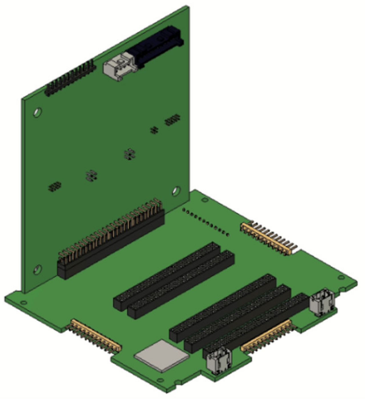
On the other hand, the backplane board (BPB) approach uses a common interface board, where all the other internal PCBs are connected to a motherboard, as shown in Figure 1.
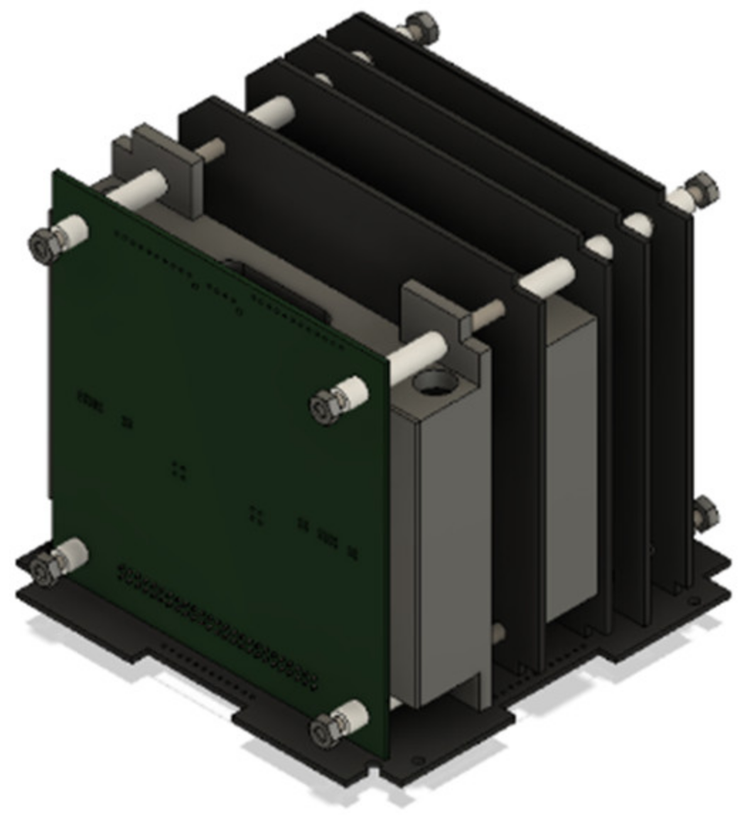
In terms of mechanical support, similar to the PC/104, four long stacking rods connect all of the individual PCB boards once electrical connection has been established with the connectors on the BPB. Cylindrical spacers are inserted into the rods between each consecutive PCB stack to constrain their position, as shown in Figure 2. Recently, several universities and some commercial vendors have increasingly adopted this interface approach, as it provides better flexibility in electrical connections. For instance, the University of Würzburg in Germany developed a UWE-4 satellite in collaboration with other institutions that implements a backplane board electrical interface [17]. The backplane board type of interface is also the currently preferred approach used on most of the satellite missions at the Kyushu Institute of Technology (Kyutech) due to its high modularity [16]. So far, 19 CubeSats have been built based on the backplane style and 16 satellites have already been launched.
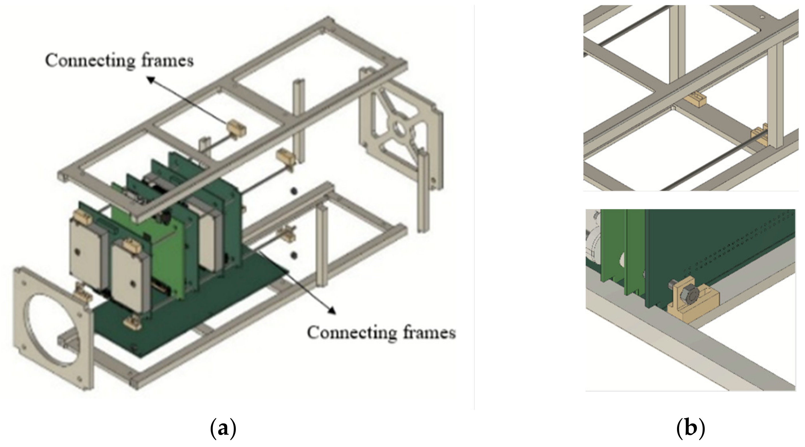
However, from a fast delivery and quick assembly point of view, both electrical interface approaches with a stacking-type mechanical interface still pose some fundamental problems, mostly due to the mounting method of internal subsystems using long stacking rods. The method of inserting these long screws through the PCBs and the structure generally requires some level of effort for maintaining the alignment in this conventional type mechanical interface. The placement of the spacers between the PCBs particularly is often a challenging task during assembly, due to the required simultaneous task of inserting the stacking rods and placing the spacers, aligned with the holes in the PCBs, not to mention the substantial number of structural parts utilized, which consumes time during assembly. This potentially introduce workmanship errors to the assembly process, damaging the connector pins, etc. In addition, the additional frames used to connect these stacking rods to the structural frames, as shown in Figure 3, increase the total part count of the structure.
Both the above electrical interface approaches characterize the most conventional CubeSat interfaces. Several design solutions have been proposed to address the issues of flexibility and modularity. This study investigates similar design concepts available and tries to analyze their feasibility for the assumed applications.
A commercial space company developed a card-slot-type structural design in which individual subsystems are inserted into defined slots using special spacers holding the internal subsystems. An example can be seen on the company’s website [14]. This design concept can solve the above issue of interdependency between subsystems during integration. However, the retractable PCB holder/spacer used to prevent the direct contact of the subsystems with the main structural frames increases the total structural part count and possibly the complexity during assembly.
Another study conducted by Istanbul Technical University for the PSAT-II mission [18] considered a modular 3U structure design with evenly spaced slit features on the interior faces of the four main frames to mount the internal subsystems. The PCBs were inserted into these tacks. The design in the study aimed to increase flexibility in rearranging internal subsystems, without the need to change the design of the structure, and to demonstrate it on a standardized bus in orbit. However, despite its concept of modularity, the study did not clearly show the electrical interface methods, nor the mechanical interface used to mount the internal PCB into the slots. insertion of PCBs directly into the given slits could potentially damage the PCB as well as the sensitive components, especially in the launch environment.
In general, the most important efficiency parameters, such as structural part count and number of assembly steps, which directly influence the level of complexity of the integration, have not been adequately addressed in either design. In fact, the complexity and the number of assembly steps has a direct relationship with the number of parts that exist. In addition, complexity can be a result of the mechanical interface method implemented. Therefore, it is important to have a platform where few parts and joints are needed for integration, with an assembly procedure easy to comprehend for someone who is not familiar with the tasks.
Once a design is optimized to the point where it has few structural parts and subsystems with little interdependence, it is important to standardize the platform so that few design changes are required in subsequent developments. This can be achieved by defining the interface between the satellite subsystems and the structure. At the same time, it is also important to allow some level of flexibility for subsystems or payloads with unique dimensions to fit into the structure without difficulty.
The goal of this research is to develop a flexible standard efficient 3U STM (structure and thermal model) which is suitable for mass production applications. The design concept is developed as an STM for an ongoing 3U CubeSat project.
Recalling the common conventional type of structure, which is made up of several structural frames, rods, and plates, it is important to address the associated challenges. Therefore, a slot-based structural design is proposed with a unique interface between the internal PCB and the structure. The following are design parameters defined to evaluate the design objective.
The design goals:
- A reduction in the number of parts;
- A reduction in complexity;
- A reduction in the number of assembly steps;
- To show the scalability of the design to the 1U CubeSat form factor;
- To comply with all interface and launch requirements;
- An adequate volume for the communication payload.
These design goals are used as evaluation parameters to compare the new design concept against the existing traditional, conventional CubeSat structural designs. After this initial phase of design, an EM and FM models are currently being developed with further design optimization. In this study, the initial STM development, from concept design to manufacturing and testing, is explained.
The purpose of the present paper is to develop a flexible and modular standard 3U CubeSat structure that is suitable for highly efficiency-demanding mass production applications. The novelty of this paper is the interface method used to mount the internal subsystems onto the slots, which provides a much lower part count with an easy assembly technique compared to the existing slot-type structural platforms. In addition, the slots are standardized to reduce the need for a change in the interface design of internal components, while at the same time facilitating the easy relocation of subsystems within the platform during the configuration definition phase.
This paper consists of seven sections. The second section describes the conceptual development of the structural design. The suitability of the proposed design is evaluated against the existing structural platform in the third section. The assessment results are analyzed in the fourth section. The fifth and the final sections provide the conclusion and directions for future work.
2. Conceptual Development of Structural Design
To come up with a design that solves the aforementioned issues, several design concepts are considered at the beginning of development based on the defined design goals. The CubeSat standard interface developed by California Polytechnic State University is used as a design reference [19]. An example of a design specification document is the JAXA’s Japanese Experimental Module (JEM) Payload Accommodation Handbook, for those CubeSats that are released from the JEM Remote Manipulator System using the JEM Small Satellite Orbital Deployer J-SSOD installed in [20]. In addition, constraints from previous heritage subsystems are taken into account during the development of the design concept. Satellite bus subsystems, such as the electrical and power subsystem (EPS), onboard computer (OBC), and communication (COM) boards, have been used for several previous projects. Since design modification of these subsystems costs a significant amount of money, the basic shape and dimensions of these internal PCBs are kept and used as additional design constraints.
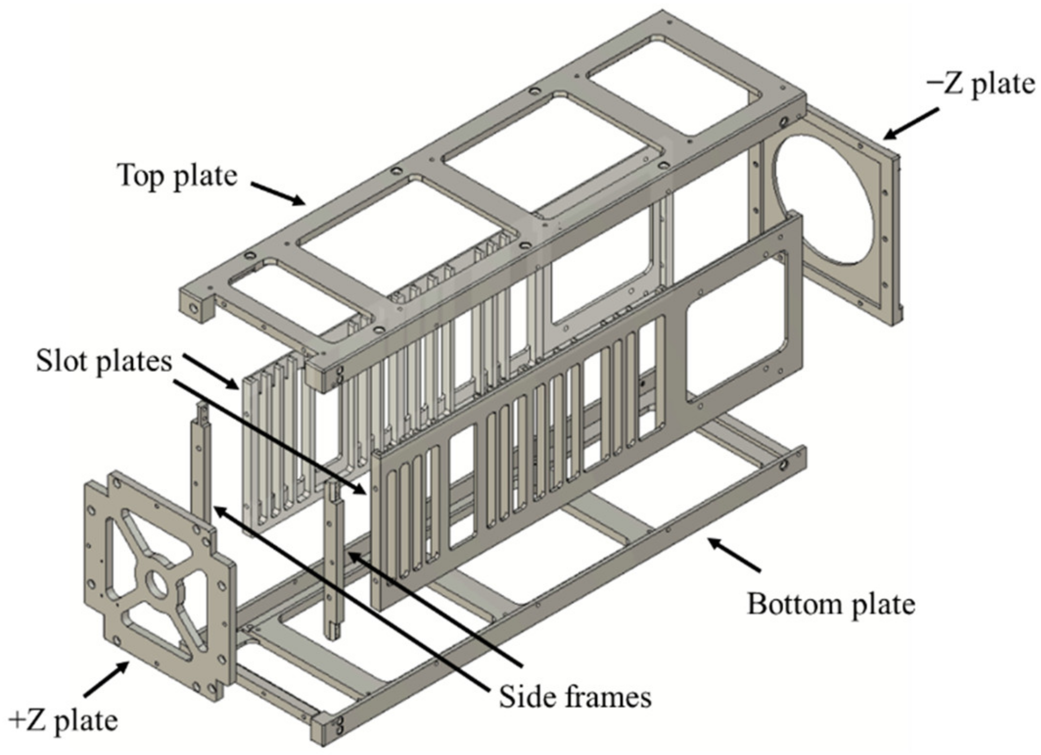
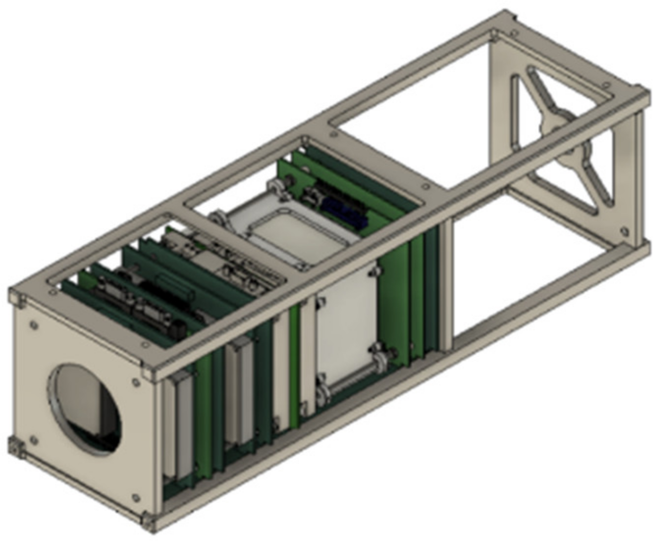
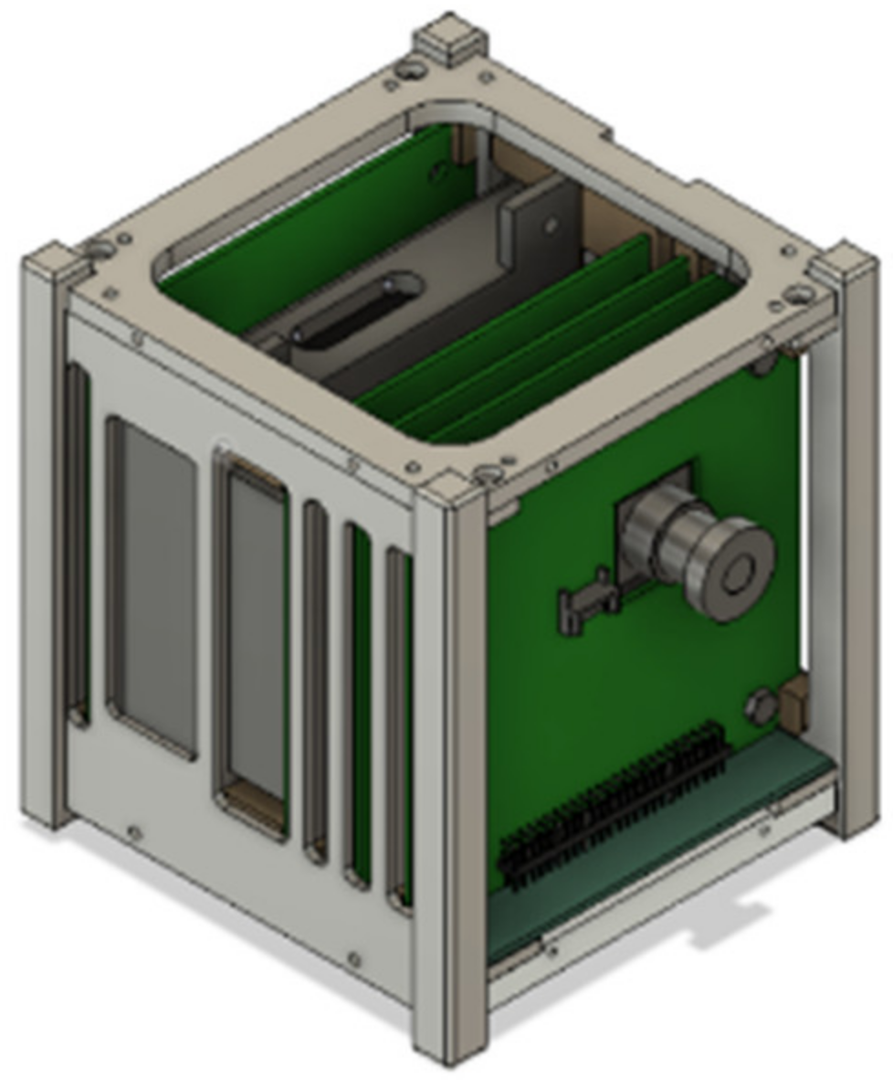
During the development of this new design, Fusion 360 software is used to model the structure. After a series of design iterations and evaluations, a slot-based design concept is chosen for a 3U STM using a total of eight aluminum structural components, as shown in Figure 4. Two parallel mirror slot plates are designed to mount the satellite’s internal bus and payload. They are attached to the two bottom and top plates. Additionally, for this STM, two side frames on the Plus and Minus X axis are used to connect the top and bottom plates to give the structure extra stiffness and provide additional support for PC/104 standard subsystems such as the ADCS units.
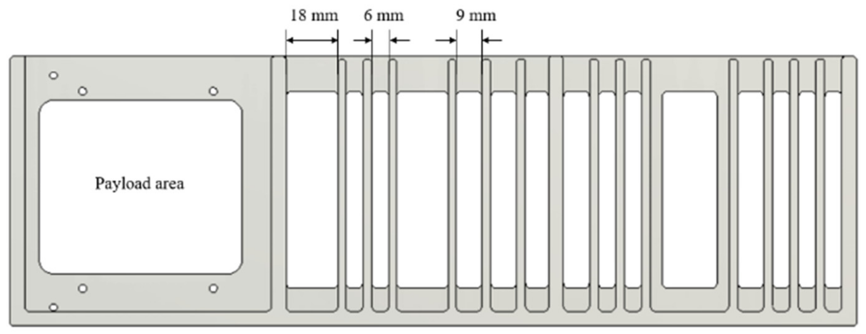
2.1. Standardizing the Slots
Greater attention is given to standardizing the width of the slot rails to reduce the variety of spacers used. To allow easy interchangeability between subsystems, three standard slot widths are defined, as shown in Figure 5: 6 mm, 9 mm, and 18 mm. Besides these standard slot widths, free-sized slots are also considered to accommodate a few oversized components, depending on the type of mission. In this particular design, the battery and the communication payload are assumed to have relatively large sizes; therefore, slots of 27 mm and 85 mm in width were adopted.
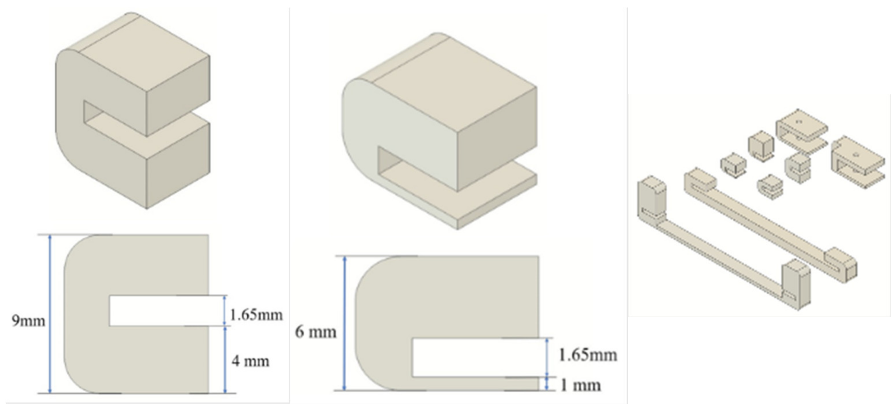
2.2. PCB Holder (Spacers)
Internal subsystem components, mostly PCB boards, are inserted into these standard slots using a set of special PCB holders (spacers) made of softer plastic material to protect the sensitive surface of the PCB. The spacer removes the need for long screw rods to mount the internal subsystems, as in the case of conventional CubeSat design. The spacers’ width is derived from the defined slot width. The spacers also have a cutout slit according to the thickness of each PCB or component, as shown in Figure 6. They are attached to the PCBs at four corners by just applying a small push force for a snap-fit. The tolerance of the cutout on the spacers should correspond to that of the PCB/components’ thickness tolerance. Similarly, the tolerance of the spacers’ width should also correspond to the tolerance of the slot width on the structure.
Regarding the spacer material, different plastic materials were assessed. However, PEEK (polyether ether ketone) was chosen due to its high strength and stiffness.
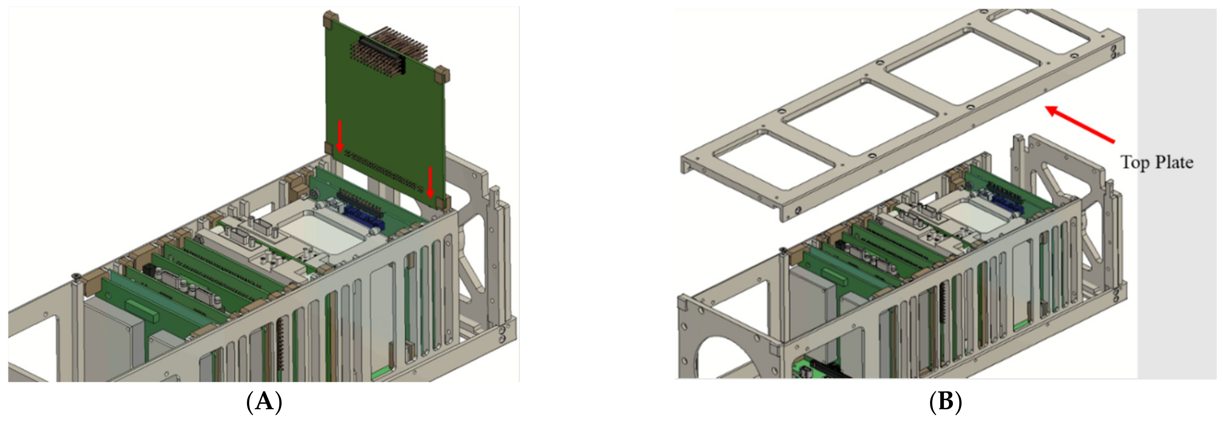
2.3. Internal Subsystem Interface Method
When the PCBs are to be inserted into the slots, the spacers are simply attached to the PCB edges at the four corners. The PCBs lock themself between the slot plates and bottom plate once the connection has been established electrically to the backplane board (BPB). The tolerance of the spacers is designed to allow the easy slide action of the PCBs during insertion and removal. The top plate fully encloses the PCB assembly, constraining the movement inside, as shown in Figure 7.
2.4. Finite Element Analysis (FEA) and Environmental Test
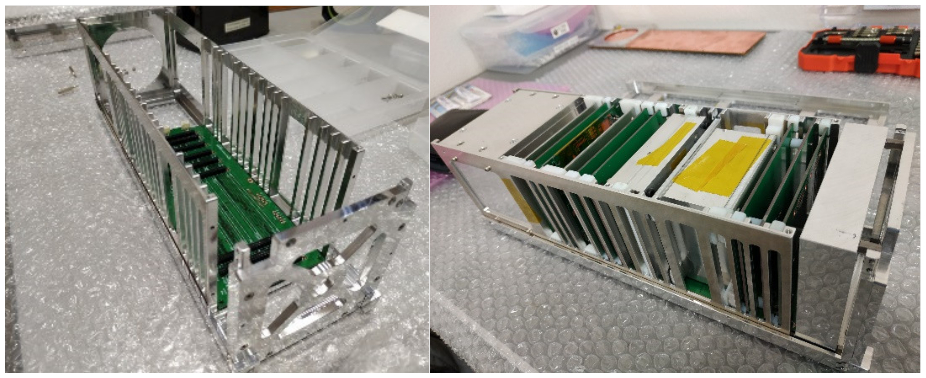
After developing the 3D model of the STM, finite element analysis (FEA) was carried out to check the stiffness both on individual components and assembly levels using the Autodesk Fusion 360 simulation environment. The model was simplified by removing rounds and chamfers. A total weight of approximately 3.6 kg was assumed to resemble the actual total weight of the satellite at the time of the STM phase. In addition to the frequency analysis, static analysis was also conducted. All the boundary conditions were applied according to the JAXA requirement handbook [20].
The production of the STM was ordered after confirming the analysis results (Figure 8). The lesson learned when placing the production order was that the tolerance requirement of the slots as well as spacers should be carefully specified and checked, as the spacers must easily slide into the slot when assembling the PCBs. The parts were assembled using dummy internal and external subsystems, which have similar mass. Then, a vibration test was conducted to verify whether the satellite could survive the severe launch environment. Different launch loads, such as random and quasi-static vibration loads, were applied to the satellite. Since the satellite is expected to be deployed from ISS, a shock test was not necessary. Qualification-level random and sine-burst vibrations were applied to the test article. Modal surveys were taken on each occasion before and after the random and sine-burst vibration to check whether the signature of the fundamental frequency had shifted. The vibration results are discussed in Section 4.1.
3. Design Assessment Methods
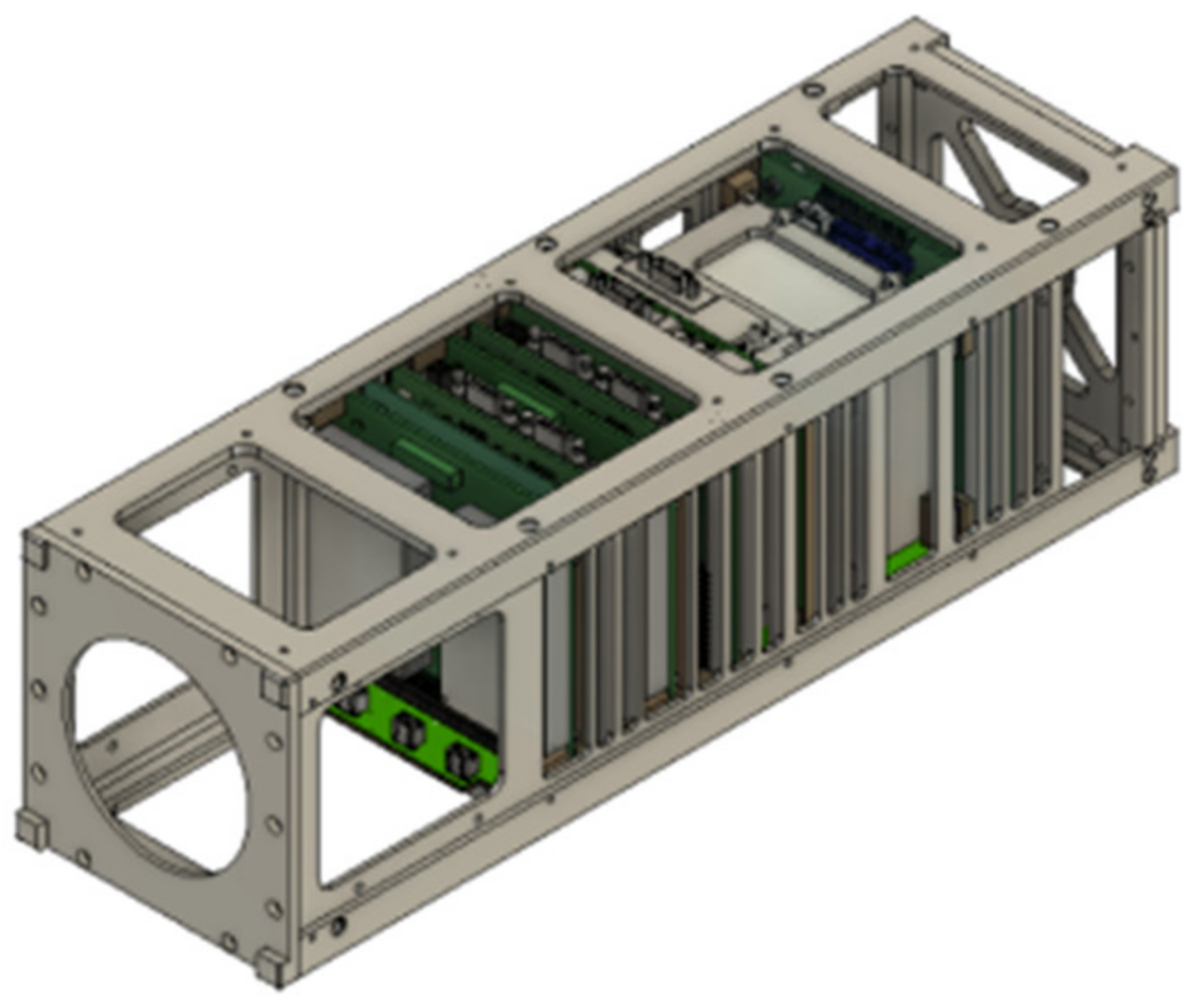
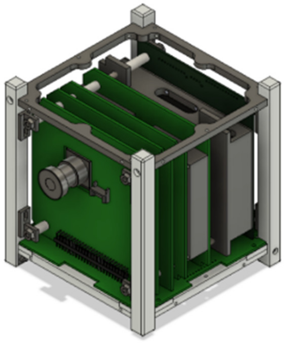
The proposed 3U STM design was critically assessed against the design goals. Since a 3U satellite has not been developed by Kyutech in the past and an actual satellite was not available to evaluate with, for assessment purposes, a demo 3U CubeSat model based on the conventional type was modeled with a backplane board electrical interface. The structure utilizes several long rods to stack up the PCBs, as shown in Figure 9. To avoid any design merits due to the design difference between the two concepts during the assessment, the quantity and shape of the basic structural parts, such as the top, bottom, and side plates, are kept similar. This helps the assessment to focus on the interface method used between the main structure and internal subassembly instead of the change in design. However, often the conventional design may only have four rails along the Z axis instead of plates and connecting rods in actual case.
As previously described, important evaluation parameters, such as part and assembly count analysis and complexity analysis, were used to assess the design goals to measure the impact of the change in design on the integration efficiency of mass production missions. First, the count analysis was conducted by comparing the total quantity of only structural parts, such as plates, frames, spacers, and fasteners. The internal subsystem components were not included in this analysis because that may vary depending on the mission type. Second, complexity analysis was carried out to measure the level of difficulty encountered during the integration phase. Then, the scalability of the design concept to other CubeSat form factors was demonstrated using a 1U platform. Since this study focuses on 3U CubeSat, due to the satellite mission requirement, the new design concept was developed for that purpose. However, it is important to assess its scalability. Due to the popularity of the 1U CubeSat platform in the CubeSat community, checking the scalability of the 3U slot-based design is particularly important. A similar assessment of count and complexity analysis was conducted by comparing this platform with the previous 1U conventional-type BIRDS-3 satellite platform, which was developed by Kyutech. The BIRDS-3 satellite has already finished its two-year mission in ISS orbit. Finally, the assembly step count was used to evaluate the speed at which each assembly action was carried out. Here, the steps are for the complete satellite assembly only, without the solar panels.
3.1. Count Analysis
In this analysis, the quantity of primary structural parts of both the 3U flexible structure and conventional-type demo model is considered, as shown in Figure 9 and Figure 10. For easy visualization, the structural parts are categorized into four groups: the main structural frames, which include rods and rails; spacers; long rods; and fasteners. This helps to visualize the major changes that contributed to the total difference. Since the quantity of screws affects the assembly process, structural screws for both designs are included in the analysis. These screws are the one that are used to secure the internal satellite components onto the structural frame. The screw count reflects the existing number of joints in the design and how parts are interconnected in the system.
3.2. Complexity Analysis
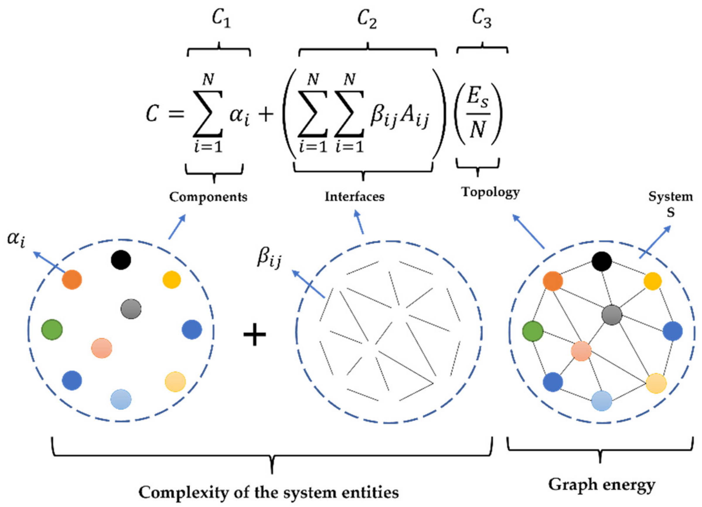
To evaluate design complexity, complexity metrics developed for the industrial assembly were used based on a modified version of Hückel’s Molecular Orbital Theory. This metric is used to calculate the complexity of systems from different perspectives [21]. In this complexity measurement, total system complexity has three variables: The first variable, , measures the complexities of each component on the individual level. The second complexity variable, , measures the complexity during a pairwise interaction (liaison relationship) of two or more components. The last variable, , is a topology complexity that measures the effect of system architecture or the arrangement of the different interfaces. Thus, the total complexity of the satellite can be calculated with a combination of these three variables using Equation (1). The detailed derivation and explanation of the metrics and each variable can be referred to in [22] (p. 48). The total complexity of the structural assembly of the satellite provides a very good piece of information about the complexity/difficulty level of the two design concepts, especially during integration. System complexity can also easily be visualized using a liaison diagram, as shown in Figure 11.
The first complexity variable of the satellite is the summation of the complexity value for all satellite components, and can be calculated using Equation (2), where represents the complexity of the satellite components, and i and Ns denote the total number of parts forming the satellite. This indicates the technical/agronomical difficulty/efforts associated with the development and management of each of the assembly components in isolated conditions.
Similarly, the liaison’s complexity of assembly, , is the sum of all the complexities in the pairwise interaction between two linked structural components and is calculated using Equation (3) below. The variables and denote a binary adjacency matrix derived from the components that have physical interaction in the assembled state.
On the other hand, in the last term, is a global measure that encapsulates the inherent arrangement of connections and is calculated by the graph energy [23]. Note that the term requires knowledge of the complete system architecture and signifies a global effect, the influence of which could be perceived during the system integration phase [22].
The complexity of the product’s topology, , is computed by
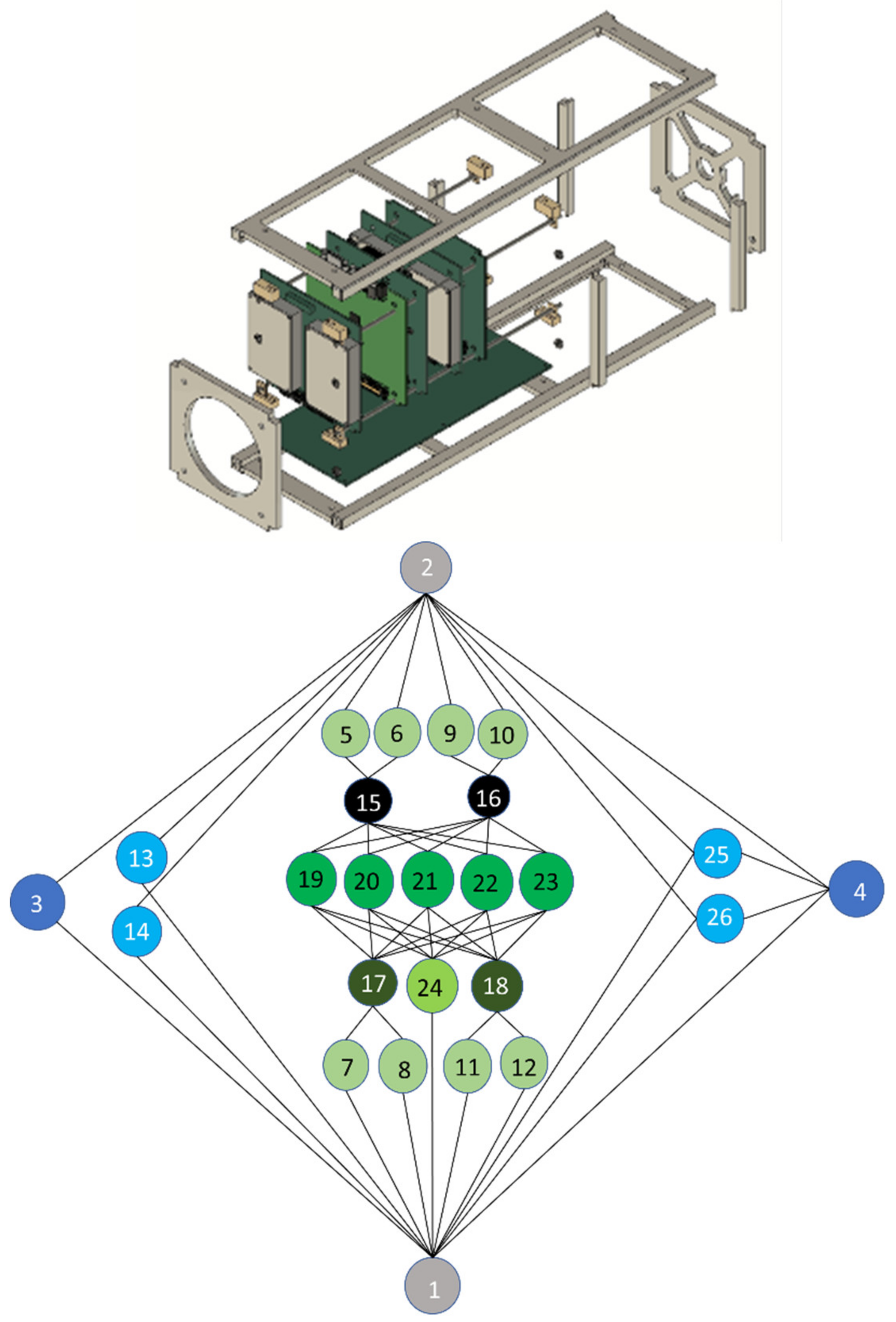
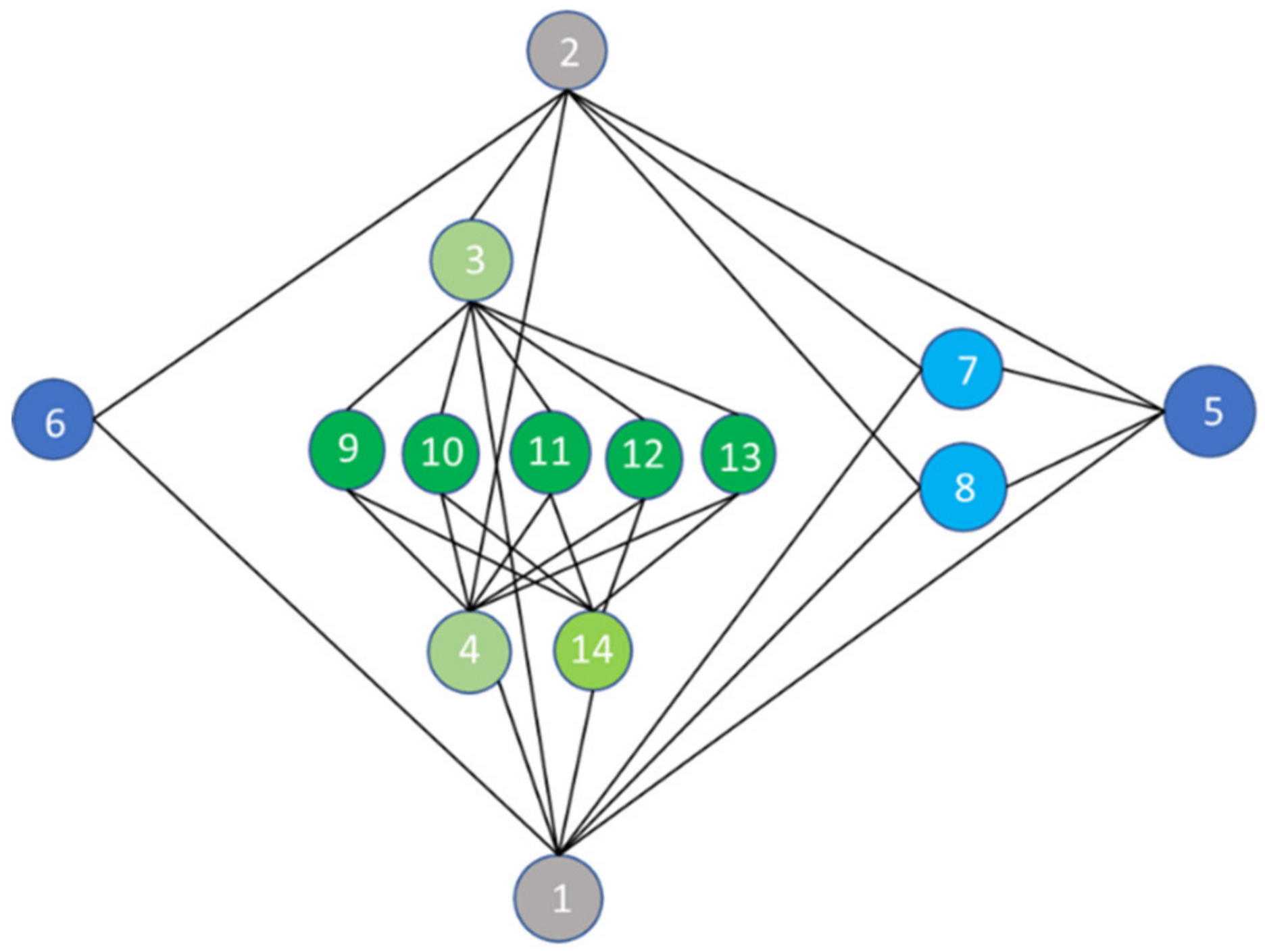
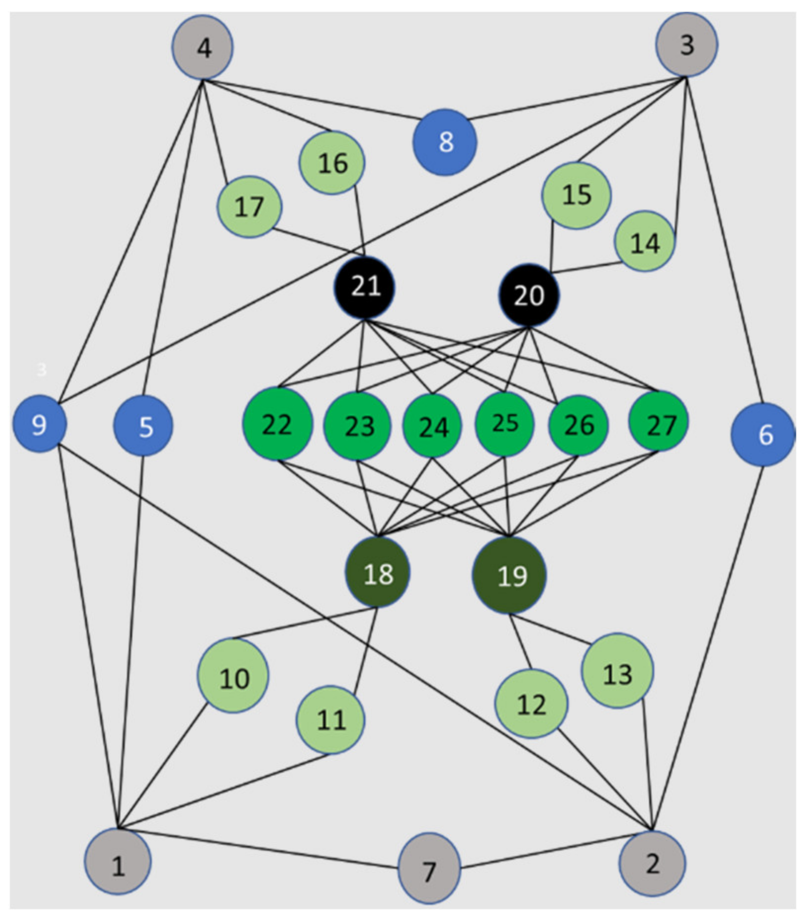
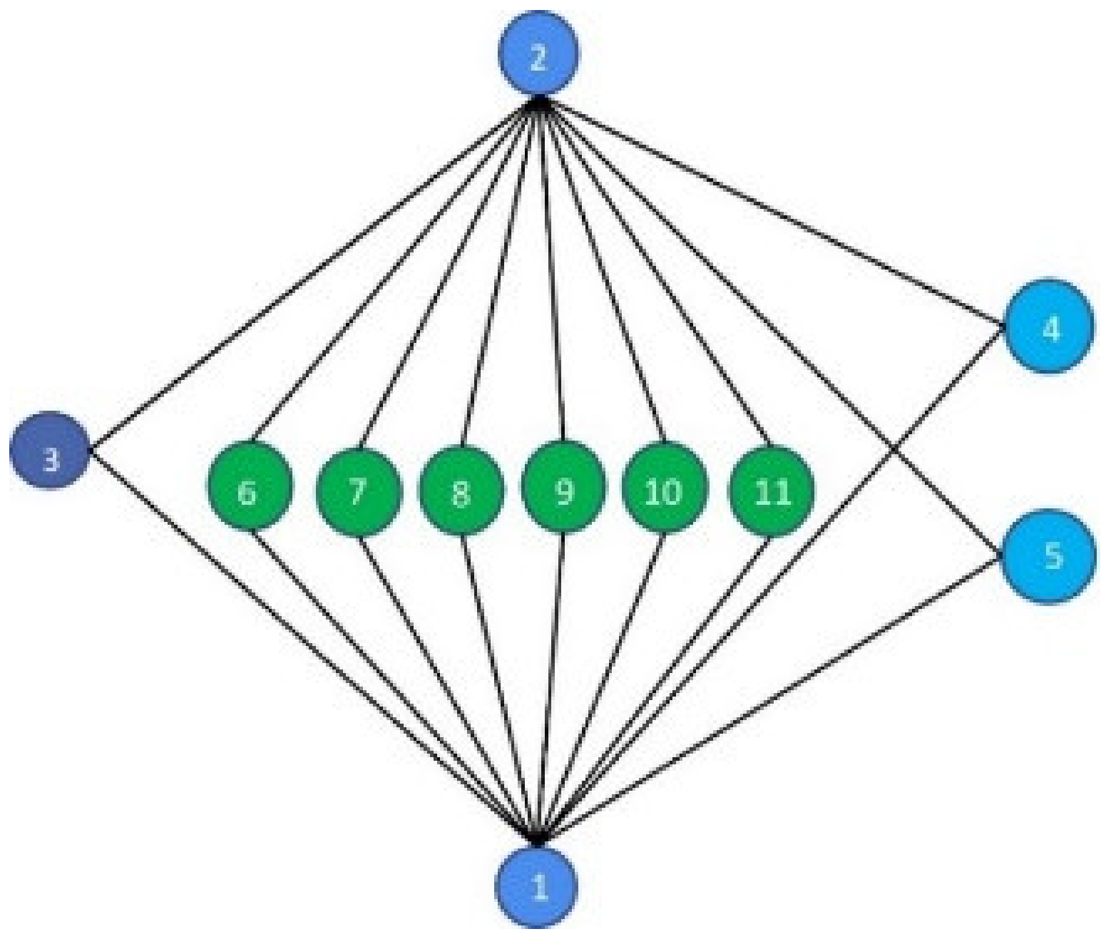
The assembled system can be expressed graphically using a combination of components and liaisons. The components can be essential components that behave as a single unit, quasi-components that are used to connect the essential components, and virtual components, which are non-mechanical components such as solders or glues. However, for simplicity, the graphical expression of the satellite only shows the essential components in compact form. In the diagram, the components are denoted by circular nodes, whereas the liaisons are denoted by edges, as shown in Figure 12 and Figure 13. The spacers and screws are considered quasi-essential components and therefore are not taken into consideration in this liaison diagram. The satellite components represented by the nodes are listed in Appendix A in Table A5.
4. Results
4.1. Structural Analysis and Vibration Test Results
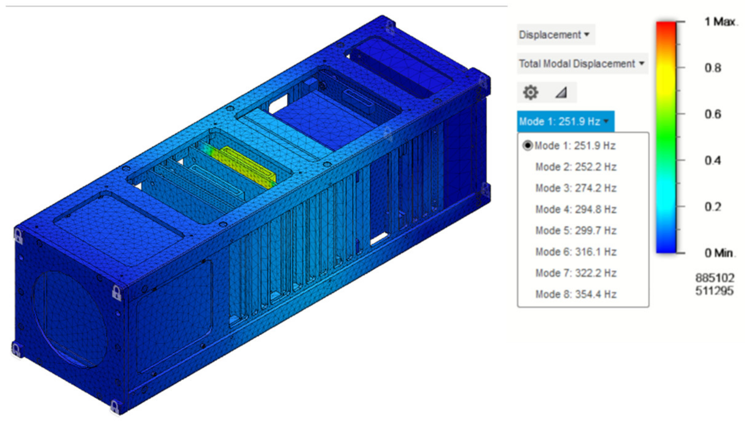
The results of frequency analysis show that the first mode of vibration in the fully assembled state of the satellite is 251.9 Hz, as shown in Figure 14, which is well above the minimum requirement of 60 Hz specified in the JAXA accommodation handbook document [20]. On the other hand, the maximum von Mises stress when the expected launch load is applied is 96.09 MPa, 111.8 MPa, and 99.22 MPa in the X-, Y-, and Z-axis, respectively. The safety margin is calculated using these stress values.
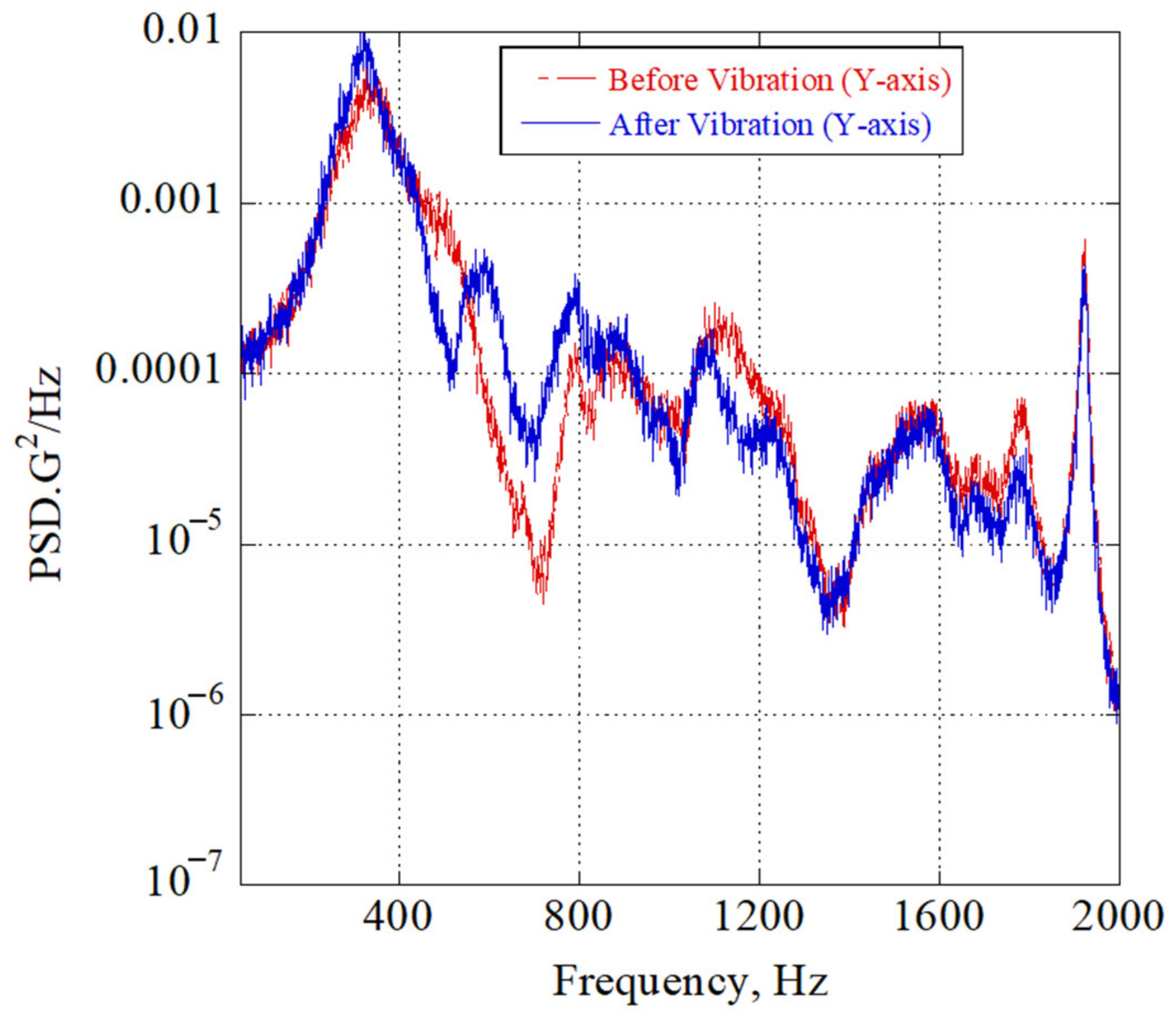
In addition, random and sine-burst vibration tests were conducted at the Kyutech Nanosatellite development facility. All the test results show that the satellite’s fundamental frequency did not change before and after the vibrations, as shown in Figure 15.
4.2. Evaluation Result for Count Analysis
The count analysis results for the 3U CubeSat are shown in Table 2. Both the part and screw count show a considerable amount of change in favor of the slot-based design concept. A 42% reduction is achieved by changing the interface method of internal subsystem, since the design merit is out of the equation because the designs of major structural parts in both concepts are similar in shape and quantity. Such a significant improvement, from 14 to 8, attained due to the reduction in the number of structural parts, such as the connecting frames and long rods that hold the PCB stacks and spacers. The conventional design utilizes many spacers that must be mounted between each stack, whereas in the case of the slot design, only four spacers are used for each PCB. The number of structural screws, however, does not show substantial improvement, being only 5%. This is because this STM utilizes several redundant structural screws. This point was taken as a potential area for improvement on the current EM model.
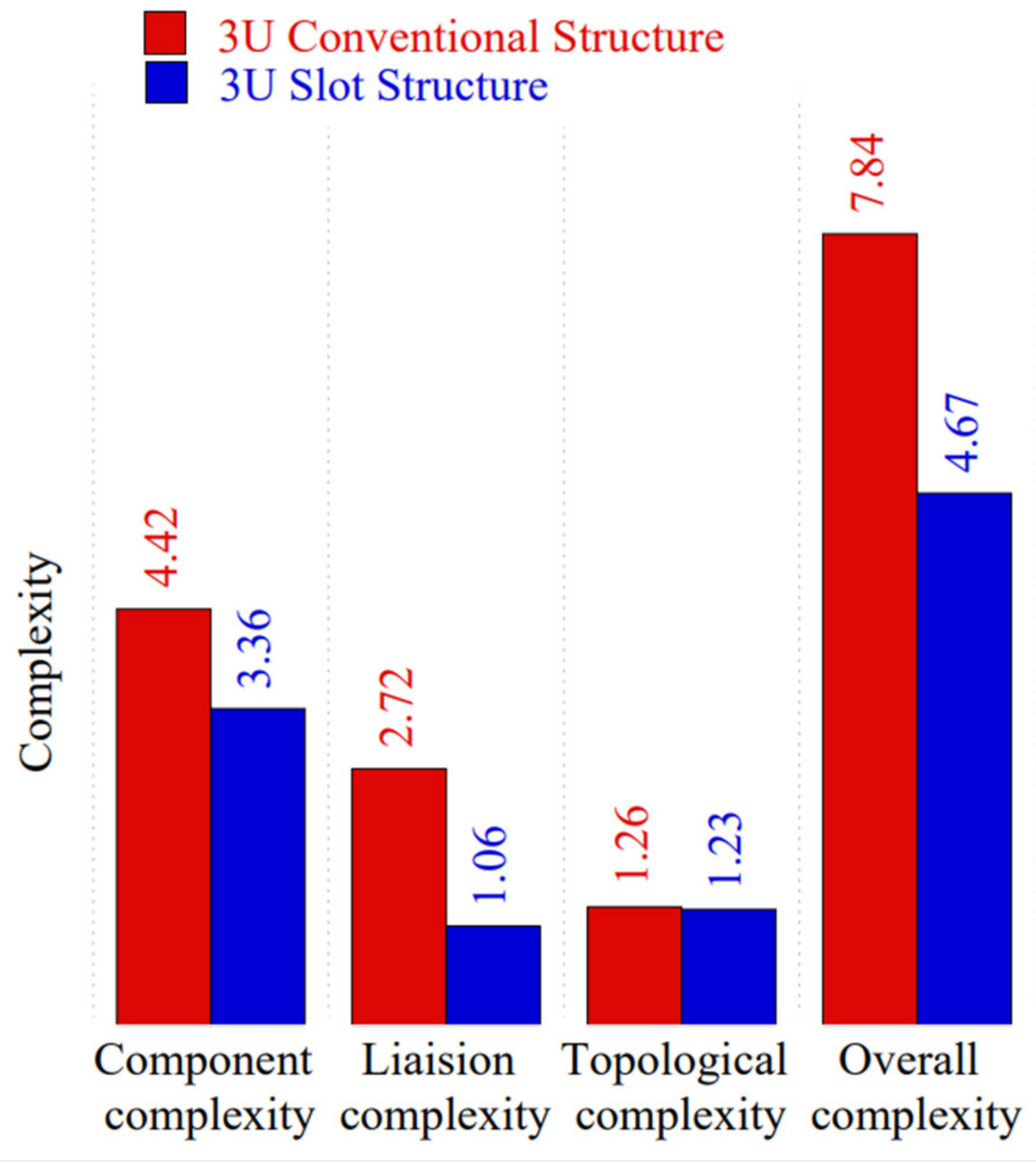
4.3. Evaluation Result for Complexity Analysis
The complexity of both satellite design concepts is computed using Equation (1). Figure 16 shows the comparative value of each complexity variable of both 3U designs. The complexity analysis reveals that the overall complexity of the slot-based design is reduced by 40.43%. All the sub-complexity variables show an improvement in comparison with the conventional-type structural design. The reduction in the component complexity by shows a reduction in the level of difficulty when handling individual components in the case of the slot-based design. The improvement in liaison complexity is rather noticeable, being approximately 61.03%. Due to the small number of structural screws and components, as well as the way they are brought together, without the need for long screws, it is possible to reduce the liaison complexity. From a global perspective, the intricateness of the overall integration is also improved, but by a small amount.
4.4. Evaluation Result of Assembly Steps
As described before, the steps taken to assemble all satellite components, except the structure, are counted. The process of attaching screws and spacers is not considered during the count. Assuming that the spacers are already attached to the PCBs, the total number of steps required to assemble the conventional structure is 29, whereas it is only 12 for the slot-based structure. This represents an improvement of around 58%.
4.5. Evaluation Result of Design Concept Scalability
In addition to the above evaluations performed on the 3U CubeSat, the scalability of the concept down to the lower CubeSat form factor was verified. The BIRDS-3 satellite (shown in Figure 17) is used for this assessment. BIRDS-3 is a 1U CubeSat with a structure based on the conventional design concept. Similar evaluation methods were employed to check its suitability for highly efficiency-demanding mass production applications. For the purpose of this evaluation, a slot-based 1U STM was designed (shown in Figure 18) and manufactured. Then, it was compared with an existing conventional-type BIRDS-3 platform. A similar liaison representation is used to show the relationship between components in the assembly in Figure 19 and Figure 20.
4.5.1. Count Analysis
In the count analysis, only the primary structural parts, such as rails, plates, rods, spacers, and fasteners, are considered. They are subcategorized accordingly in a similar way for the 3U models, as shown in Table 3.
A similar result is obtained for the 1U-size design. The total number of screws is reduced by 33.33% for the slot structure, whereas a 50.98% reduction is achieved in the total part count, which includes structural parts and spacers. The BIRDS-3 CubeSat uses 51 structural parts, including the long mounting rods, whereas the total number of structural parts of the slot-based design is only seven. This significant reduction is due to the withdrawal of the staking rods and the associated support frames.
4.5.2. Complexity Analysis
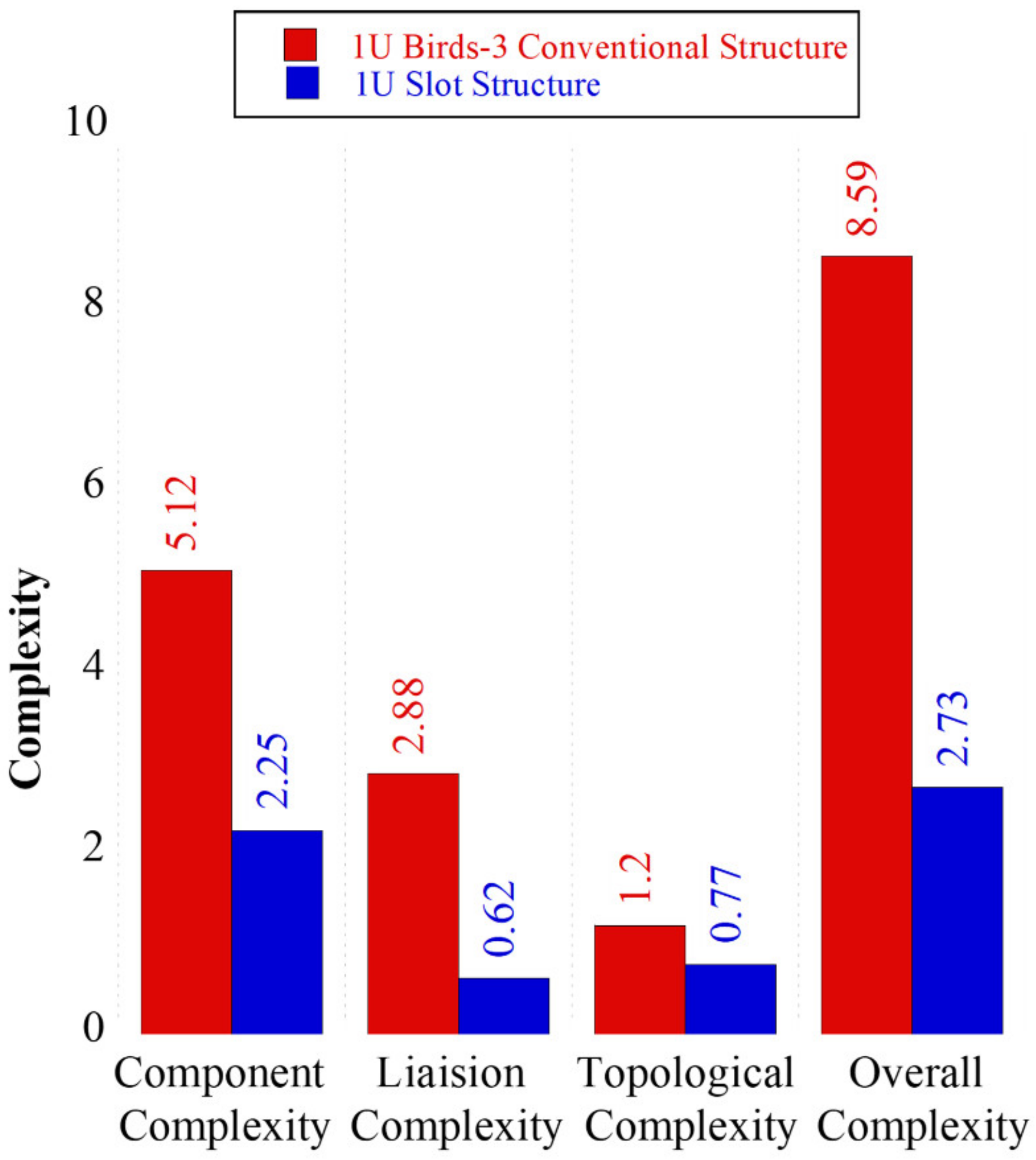
During integration, there is also an impact on the overall reduction in complexity. In the case of the slot-type design, the individual PCBs and payload components are independently mounted in their designated slots using a special spacer, avoiding interdependency between the subsystems, which increases easiness of accessing components quickly. This effect can be easily observed with the value of the liaison parameters, which shows a 78.45% reduction. The total complexity of the conventional design of BIRDS-3 is 8.59, whereas it is only 2.73 for the slot-type concept, which is, overall, 68.22% drop. Figure 21 below illustrates the general comparison of the complexity of both 1U designs.
4.5.3. Assembly Steps
In terms of the number of assembly steps, assembling the BIRDS-3 model requires a total of 16 steps. On the other hand, only five steps are required for the 1U slot-type design. This notable difference is due to the reduction in the number of structural parts. The slot-based design utilizes 25 structural parts, which is approximately half of that for the BIRDS-3 structure.
5. Discussion
The new slot-type structural design concept was manufactured and verified with environmental tests to confirm its bottom-line requirement. Both the random and sine-burst vibration shows its compliance to the minimum mechanical strength and stiffness requirements. According to the JAXA accommodation handbook, the minimum natural frequency of satellites is defined as 60 Hz. The measured natural frequency of the STM design for 3U was around 310 Hz.
The assessment results from the count and complexity analyses strongly suggest that the new slot-based structural design showed superior advantages by providing a more efficient integration process. It was possible to reduce the structural part count of the conventional design by 42% and 51% for the 3U and 1U satellites, respectively. The improvement in the part count provides three major benefits. First, the few required assembly steps to finish integrating the satellite led to an increase in the speed of the entire process of satellite development. On the other hand, having fewer structural parts also means a reduction in manufacturing costs. The cost is also directly related to the amount of tolerance required. A higher stack-up tolerance also leads to higher tolerance on individual parts level. As the number of parts increases, the stack-up tolerance increases to achieve the tolerance requirement defined by the CubeSat design specification, which causes a dramatic increase in production costs. The last advantage acquired with the minimum part count is its contribution to the reduction in complexity during integration.
Complexity is a key factor that decides the level of simplification of the integration that impacts productivity. The complexity analysis shows a similar improvement as the part count analysis. The 3U slot design provides 40.43% reduction as compared to the conventional-type designs. On the other hand, a 68.02% change in the complexity for the case of the 1U slot design shows a significant change.
As discussed before, the complexity of the assembly increases with the number of components and joints. An increase in complexity usually leads to workmanship errors due to difficulty grasping the assembly process. Despite the overall improvement achieved, the amount varies in terms of the level of sub-complexity variables. The minimum recorded improvement is in topological complexity, which indicates the need for further refinement in design. Based on the identified issues, further refinement in the design is being carried out for the current FM model. It is expected that upon the completion of the current FM model, the count and complexity values shall improve even further. In this design, the internal subsystems are standardized within the dimensions of 90 mm (about 3.54 in) by 86 mm (about 3.39 in); however, future work will consider enhancing the flexibility to accommodate components that are not standard enough to fit into the defined standard slot widths.
Besides these major assessments, the implication of the reduction in part count and complexity, of the assembly step was evaluated. It takes 12 steps to complete the 3U slot structure assembly which is 58% reduction. The reduction in the number of assembly steps by more than half shows the method’s suitability in terms of efficiency for fast integration missions. The scalability of the concept to lower the CubeSat factor demonstrates that this highly efficiency-demanding mission has potential feasibility on a 1U or higher form factor CubeSat platform.
6. Conclusions
As mass production applications using CubeSats are expanding, it can be deduced that an increase in productivity through the enhancement of flexibility and integration speed looks particularly important for the profitability and success of these missions. In this study, a highly flexible and easy-to-use 3U and 1U slot-based structure was developed, which facilitates easy and quick integration. It is believed to increase the reliability of satellite integration by reducing the complexity that case human errors during the integration and testing phases. Both structural analysis and vibration tests show that the developed model is stiffened and strong enough to withstand expected severe launch loads.
Finally, the design goals are evaluated against the conventional CubeSat structural design using the part and assembly step count, as well as complexity analysis. The results show significant improvements in the critical design parameters. The scalability of the concept is also examined by developing an equivalent 1U slot-type model showing similar design outputs. This 3U design concept is currently being implemented on one of Kyutech’s mass production CubeSat projects, with additional improvements.
However, the acquired advantages are more noticeable, especially for missions where the total mass of the satellite is not critical. However, in addition to an improvement in the design, several other options are being explored to reduce the total weight of the structure. In future work, the employment of new production techniques such as additive manufacturing is believed to provide further enhancement for this design concept.
Author Contributions
Conceptualization, E.E.A. and H.M.; methodology, E.E.A., H.M. and M.C.; software, E.E.A.; validation, E.E.A., H.M. and M.C.; formal analysis, E.E.A.; investigation, E.E.A. and H.M.; resources, M.C. and H.M.; data curation, E.E.A., J.R.C.-A. and H.M.; writing—original draft preparation, E.E.A.; writing—review and editing, E.E.A., J.R.C.-A., H.M. and M.C.; visualization, E.E.A.; supervision, H.M. and M.C.; project administration, J.R.C.-A., H.M. and M.C.; funding acquisition, H.M. and M.C. All authors have read and agreed to the published version of the manuscript.
Funding
This research was funded by Ministry of Economy, Trade and Industry (METI), Japan under the grant. “International Standard Development for Energy Conservation (International Standardization of CubeSat Interface)” with grant number [FY2021-10]. The APC was funded by METI.
Institutional Review Board Statement
Not applicable.
Informed Consent Statement
Not applicable.
Data Availability Statement
Not applicable.
Acknowledgments
The authors would like to acknowledge the support of the Japanese Ministry of Economy, Trade, and Industry through the Promotion of Energy Saving and Related International Standards.
Conflicts of Interest
The authors declare no conflict of interest. The funders had no role in the design of the study; in the collection, analyses, or interpretation of data; in the writing of the manuscript; or in the decision to publish the results.
Appendix A
Table A1.
The 3U conventional-type demo satellite complexity values.
| 1 | 2 | 3 | 4 | 5 | 6 | 7 | 8 | 9 | 10 | 11 | 12 | 13 | 14 | 15 | 16 | 17 | 18 | 19 | 20 | 21 | 22 | 23 | ⍺ip | |
| fhA | 1 | 1 | 1 | 1 | 1 | 1 | 1 | 1 | 1 | 1 | 1 | 1 | 1 | 1 | 1 | 1 | 1 | 1 | 1 | 1 | 1 | 1 | 1 | 23 |
| ∑ fhB | 0 | 0 | 0 | 0 | 0 | 0 | 0 | 0 | 0 | 0 | 0 | 0 | 0 | 0 | 0 | 0 | 0 | 0 | 0.4 | 0.4 | 0.4 | 0.4 | 0.4 | 2 |
| fhC | 0.1 | 0.1 | 0 | 0 | 0.1 | 0.1 | 0.1 | 0.1 | 0.1 | 0.1 | 0.1 | 0.1 | 0.1 | 0.1 | 0 | 0 | 0 | 0 | 0.1 | 0.1 | 0.1 | 0.1 | 0.1 | 1.7 |
| fhD | 0.2 | 0.2 | 0.2 | 0.2 | 0.2 | 0.2 | 0.2 | 0.2 | 0.2 | 0.2 | 0.2 | 0.2 | 0.2 | 0.2 | 0 | 0 | 0 | 0 | 0.2 | 0.2 | 0.2 | 0.2 | 0.2 | 3.8 |
| Total CP1 | 4.4 | |||||||||||||||||||||||
Table A2.
The 3U slot-based satellite complexity values.
| 3U Slot Structure: CP1 of Essential Components | |||||||||||||||
|---|---|---|---|---|---|---|---|---|---|---|---|---|---|---|---|
| 1 | 2 | 3 | 4 | 5 | 6 | 7 | 8 | 9 | 10 | 11 | 12 | 13 | 14 | ⍺ip | |
| fhA | 1 | 1 | 1 | 1 | 1 | 1 | 1 | 1 | 1 | 1 | 1 | 1 | 1 | 1 | 14 |
| ∑ fhB | 0 | 0 | 0 | 0 | 0 | 0 | 0.6 | 0.6 | 0.8 | 0.8 | 0.8 | 0.8 | 0.8 | 0.4 | 5.6 |
| fhC | 0.1 | 0.1 | 0.1 | 0.1 | 0.5 | 0 | 0.5 | 0.5 | 0.1 | 0.1 | 0.1 | 0.1 | 0.1 | 0.1 | 2.5 |
| fhD | 0.2 | 0.2 | 0.2 | 0.2 | 0.4 | 0.2 | 0.4 | 0.4 | 0.2 | 0.2 | 0.2 | 0.2 | 0.2 | 0.2 | 3.4 |
| Total CP1 | 3.695652 | ||||||||||||||
Table A3.
The 1U BIRDS satellite complexity values.
| 1U BIRDS-3 Structure: CP1 of Essential Components | ||||||||||||||||||||||||||||
|---|---|---|---|---|---|---|---|---|---|---|---|---|---|---|---|---|---|---|---|---|---|---|---|---|---|---|---|---|
| 1 | 2 | 3 | 4 | 5 | 6 | 7 | 8 | 9 | 10 | 11 | 12 | 13 | 14 | 15 | 16 | 17 | 18 | 19 | 20 | 21 | 22 | 23 | 24 | 25 | 26 | 27 | ⍺ip | |
| fhA | 1 | 1 | 1 | 1 | 1 | 1 | 1 | 1 | 1 | 1 | 1 | 1 | 1 | 1 | 1 | 1 | 1 | 1 | 1 | 1 | 1 | 1 | 1 | 1 | 1 | 1 | 1 | 27 |
| ∑ fhB | 0 | 0 | 0 | 0 | 0 | 0 | 0 | 0 | 0 | 0 | 0 | 0 | 0 | 0 | 0 | 0 | 0 | 0 | 0 | 0 | 0 | 0.4 | 0.4 | 0.4 | 0.4 | 0.4 | 0.4 | 2.4 |
| fhC | 0.1 | 0.1 | 0.1 | 0.1 | 0.1 | 0.1 | 0.1 | 0.1 | 0.1 | 0 | 0 | 0 | 0 | 0 | 0 | 0 | 0 | 0 | 0 | 0 | 0 | 0.1 | 0.1 | 0.1 | 0.1 | 0.1 | 0.1 | 1.5 |
| fhD | 0.2 | 0.2 | 0.2 | 0.2 | 0.2 | 0.2 | 0.2 | 0.2 | 0.2 | 0.2 | 0.2 | 0.2 | 0.2 | 0.2 | 0.2 | 0.2 | 0 | 0 | 0 | 0 | 0 | 0.2 | 0.2 | 0.2 | 0.2 | 0.2 | 0.2 | 4.4 |
| Total CP1 | 5.115942 | |||||||||||||||||||||||||||
Table A4.
The 1U slot-based satellite complexity values.
| 1U Slot Structure: CP1 of Essential Components | ||||||||||||
|---|---|---|---|---|---|---|---|---|---|---|---|---|
| 1 | 2 | 3 | 4 | 5 | 6 | 7 | 8 | 9 | 10 | 11 | ⍺ip | |
| fhA | 1 | 1 | 1 | 1 | 1 | 1 | 1 | 1 | 1 | 1 | 1 | 11 |
| ∑ fhB | 0 | 0 | 0 | 0 | 0 | 0.2 | 0.2 | 0.2 | 0.2 | 0.2 | 0.2 | 1.2 |
| fhC | 0.1 | 0.1 | 0.1 | 0.1 | 0.1 | 0.1 | 0.1 | 0.1 | 0.1 | 0.1 | 0.1 | 1.1 |
| fhD | 0.2 | 0.2 | 0.2 | 0.2 | 0.2 | 0.2 | 0.2 | 0.2 | 0.2 | 0.2 | 0.2 | 2.2 |
| Total CP1 | 2.25 | |||||||||||
Table A5.
Nodal definition of the 1U and 3U slots and conventional designs.
| Node Number | Satellite Part Name | |||
|---|---|---|---|---|
| 3U Conv | 3U Slot | 1U Conv | 1U Slot | |
| 1 | Bottom plate | Base plate | Rail-1 | Slot-1 |
| 2 | Top plate | Lid plate | Rail-2 | Slot-2 |
| 3 | Front plate | Slot-1 | Rail-3 | Top frame |
| 4 | Back plate | Slot-2 | Rail-4 | Bottom frame-1 |
| 5 | Frame-1 | Top plate | Bottom frame-1 | Bottom frame-2 |
| 6 | Frame-2 | Bottom plate | Bottom frame-2 | PCB-1 |
| 7 | Frame-3 | Frame-1 | Top frame | PCB-2 |
| 8 | Frame-4 | Frame-2 | Frame-1 | PCB-3 |
| 9 | Frame-5 | PCB-1 | Frame-2 | PCB-4 |
| 10 | Frame-6 | PCB-2 | Frame-3 | PCB-5 |
| 11 | Frame-7 | PCB-3 | Frame-4 | PCB-6 |
| 12 | Frame-8 | PCB-4 | Frame-5 | |
| 13 | Frame-5 | PCB-5 | Frame-6 | |
| 14 | Frame-6 | Frame-7 | ||
| 15 | Rod-1 | Frame-8 | ||
| 16 | Rod-2 | Long rod 1 | ||
| 17 | Rod-3 | Long rod 2 | ||
| 18 | Rod-4 | Long rod 3 | ||
| 19 | PCB-1 | Long rod 4 | ||
| 20 | PCB-2 | PCB-1 | ||
| 21 | PCB-3 | PCB-2 | ||
| 22 | PCB-4 | PCB-3 | ||
| 23 | PCB-5 | PCB-4 | ||
| 24 | PCB-5 | |||
| 25 | PCB-6 | |||
References
- Cappelletti, C.; Battistini, S.; Malphrus, B.K. Cubesat Handbook from Mission Design to Operations; Academic Press: Cambridge, MA, USA, 2021; ISBN 9780128178843. [Google Scholar]
- Moore, G.E. Cramming More Components onto Integrated Circuits, Reprinted from Electronics, Volume 38, Number 8, April 19, 1965, Pp.114 Ff. IEEE Solid-State Circuits Soc. Newsl. 2006, 11, 33–35. [Google Scholar] [CrossRef]
- De Carvalho, R.A.; Estela, J.; Langer, M. Nanosatellites Space and Ground Technologies, Operations and Economics; Wiley and Sons: Hoboke, NJ, USA, 2020. [Google Scholar]
- Poghosyan, A.; Golkar, A. CubeSat Evolution: Analyzing CubeSat Capabilities for Conducting Science Missions. Prog. Aerosp. Sci. 2017, 88, 59–83. [Google Scholar] [CrossRef]
- Op-Ed Satellite Bankruptcies circa 2000, vs. 2020: We’ve Come a Long Way! SpaceNews. 2021. Available online: https://spacenews.com/op-ed-satellite-bankruptcies-circa-2000-vs-2020-weve-come-a-long-way/ (accessed on 27 July 2022).
- Boothroyd, G.; Dewhurst, P.; Knight, W.A. Product Design for Manufacture and Assembly, 3rd ed.; CRC Press: Boca Raton, FL, USA, 2010; ISBN1 1420089277. ISBN2 9781420089271. [Google Scholar]
- Enright, J.; Jilla, C.; Miller, D. Modularity and Spacecraft Cost. J. Reducing Sp. Mission Cost 1998, 1, 133–158. [Google Scholar] [CrossRef]
- Nanosats Database CubeSat Tables|Nanosats Database. Available online: https://www.nanosats.eu/tables# (accessed on 16 July 2022).
- NASA Small Spacecraft Technology State of the Art. Available online: https://www.nasa.gov/sites/default/files/atoms/files/soa_2021_1.pdf (accessed on 17 July 2022).
- Lovascio, A.; D’orazio, A.; Centonze, V. Characterization of a COTS-Based RF Receiver for Cubesat Applications. Sensors 2020, 20, 776. [Google Scholar] [CrossRef] [PubMed]
- GOMspace GOMspace|Home. Available online: https://gomspace.com/home.aspx (accessed on 17 July 2022).
- PUMPKINSPACE. CubeSat KitTM Structures. Available online: https://www.pumpkinspace.com/store/c4/CubeSat_KitTM_Structures.html (accessed on 17 July 2022).
- ISIS CubeSat Structures-ISISPACE. Available online: https://www.isispace.nl/product-category/cubesat-structures/ (accessed on 17 July 2022).
- C3S. Structures-C3S. Available online: https://c3s.hu/structures/ (accessed on 17 July 2022).
- PC/104 Consortium-Specifications. Available online: https://pc104.org/ (accessed on 23 July 2022).
- Tumenjargal, T.; Kim, S.; Masui, H.; Cho, M. CubeSat Bus Interface with Complex Programmable Logic Device. Acta Astronaut. 2019, 160, 331–342. [Google Scholar] [CrossRef]
- Kramer, A.; Bangert, P.; Schilling, K. UWE-4: First Electric Propulsion on a 1U Cubesat-in-Orbit Experiments and Characterization. Aerospace 2020, 7, 98. [Google Scholar] [CrossRef]
- Cihan, M.; Cetin, A.; Kaya, M.O.; Inalhan, G. Design and Analysis of an Innovative Modular Cubesat Structure for ITU-PSAT II. In Proceedings of the RAST 2011-Proceedings of 5th International Conference on Recent Advances in Space Technologies, Istanbul, Turkey, 9–11 June 2011; pp. 494–499. [Google Scholar]
- CubeSat Design Specification Rev. 14.1. Available online: https://static1.squarespace.com/static/5418c831e4b0fa4ecac1bacd/t/62193b7fc9e72e0053f00910/1645820809779/CDS+REV14_1+2022-02-09.pdf (accessed on 21 July 2020).
- JEM Payload Accommodation Handbook-Small Satellite Deployment Interface Control Document. Available online: https://iss.jaxa.jp/kibouser/library/item/jx-espc_8d_en.pdf (accessed on 5 September 2020).
- Alkan, B.; Vera, D.; Ahmad, B.; Harrison, R. A Method to Assess Assembly Complexity of Industrial Products in Early Design Phase. IEEE Access 2017, 6, 989–999. [Google Scholar] [CrossRef]
- Sinha, K. Structural Complexity and Its Implications for Design of Cyber—Physical Systems; Massachusetts Institute of Technology: Cambridge, MA, USA, 2014. [Google Scholar]
- Nikiforov, V. The Energy of Graphs and Matrices. J. Math. Anal 2007, 326, 472–1475. [Google Scholar] [CrossRef] [Green Version]
Figure 1.
BIRDS satellite BPB interface [16].
Figure 1.
BIRDS satellite BPB interface [16].

Figure 2.
Stacking of PCBs with long rods.

Figure 3.
(a) Exploded 3U model based on conventional interface methods and (b) connecting rods for mounting internal subassemblies.
Figure 3.
(a) Exploded 3U model based on conventional interface methods and (b) connecting rods for mounting internal subassemblies.

Figure 4.
Exploded view of the Slot-based 3U structural model.

Figure 5.
Slot plate with standardized slot width for 3U model.

Figure 6.
Standard 6 mm, 9 mm, and free-size spacers.

Figure 7.
(A) PCB insertion into the slots. (B) The top plate encloses the satellite assembly.

Figure 8.
Structural and full satellite assembly of STM 3U.

Figure 9.
Conventional demo 3U model.

Figure 10.
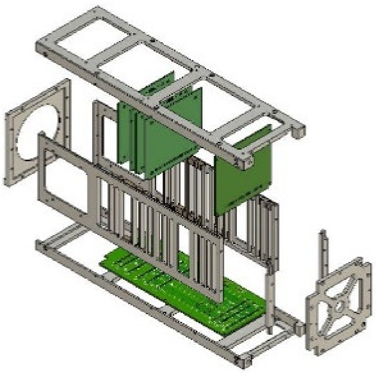
Slot-based 3U model.

Figure 11.
Elements of the overall complexity metrics shown with a liaison diagram.

Figure 12.
Liaison diagram of 3U demo conventional model.

Figure 13.
Liaison diagram of 3U slot-based model.


Figure 14.
Frequency analysis of the 3U model.

Figure 15.
Modal survey before and after random vibration on Y-axis.

Figure 16.
Complexity evaluation of 3U conventional and slot-type structures.

Figure 17.
Conventional-type BIRDS-3 1U model.

Figure 18.
Slot-based 1U model.

Figure 19.
Liaison diagram of 1U BIRDS-3 conventional model.

Figure 20.
Liaison diagram of the 1U slot-based STM.

Figure 21.
Complexity comparison of 1U conventional and slot-type structures.

Table 2.
Part count of 3U structure.
| Structure Type | Structural Screws | Rails and Frames | Stacking Rods | Spacers | Total No. of Parts |
|---|---|---|---|---|---|
| Conventional | 76 | 14 | 4 | 48 | 66 |
| Slot | 72 | 8 | 0 | 30 | 38 |
| Improvement | 5% | 43% | 100% | 38% | 42% |
Table 3.
Count analysis of 1U structure.
| Structure Type | Structural Screws | Rails and Frames | Stacking Rods | Spacers | Total No. of Parts |
|---|---|---|---|---|---|
| BIRDS-3 | 60 | 19 | 4 | 28 | 51 |
| 1U slot | 40 | 7 | 0 | 18 | 25 |
| Improvement | 33% | 63% | - | 36% | 51% |
Publisher’s Note: MDPI stays neutral with regard to jurisdictional claims in published maps and institutional affiliations. |
© 2022 by the authors. Licensee MDPI, Basel, Switzerland. This article is an open access article distributed under the terms and conditions of the Creative Commons Attribution (CC BY) license (https://creativecommons.org/licenses/by/4.0/).
Share and Cite
MDPI and ACS Style
Areda, E.E.; Cordova-Alarcon, J.R.; Masui, H.; Cho, M. Development of Innovative CubeSat Platform for Mass Production. Appl. Sci. 2022, 12, 9087. https://0-doi-org.brum.beds.ac.uk/10.3390/app12189087
AMA Style
Areda EE, Cordova-Alarcon JR, Masui H, Cho M. Development of Innovative CubeSat Platform for Mass Production. Applied Sciences. 2022; 12(18):9087. https://0-doi-org.brum.beds.ac.uk/10.3390/app12189087
Chicago/Turabian StyleAreda, Eyoas Ergetu, Jose Rodrigo Cordova-Alarcon, Hirokazu Masui, and Mengu Cho. 2022. "Development of Innovative CubeSat Platform for Mass Production" Applied Sciences 12, no. 18: 9087. https://0-doi-org.brum.beds.ac.uk/10.3390/app12189087
Note that from the first issue of 2016, this journal uses article numbers instead of page numbers. See further details here.