Article

Fabrication of Multifunctional Composites with Hydrophobicity, High Thermal Conductivity and Wear Resistance Based on Carbon Fiber/Epoxy Resin Composites

1
Beijing Smart-Chip Microelectronics Technology Co., Ltd., Beijing 100192, China
2
School of Chemical Engineering and Technology, Tianjin University, Tianjin 300350, China
3
Electric Power Company Marketing Service Center (Metrology Center), Jinan 250000, China
4
Tianjin Key Lab Composite & Functional Materials, School of Materials Science and Engineering, Tianjin University, Tianjin 300072, China
*
Author to whom correspondence should be addressed.
Submission received: 22 July 2022 / Revised: 6 September 2022 / Accepted: 7 September 2022 / Published: 19 September 2022
(This article belongs to the Special Issue Design, Synthesis and Characterization of Hybrid Composite Materials)

Abstract

:
The design and preparation of hydrophobic, wear-resistant, and thermally conductive multifunctional composites is an important direction of scientific research and application. In this study, A-CF/EP/FEP composites were prepared by incorporating APDMS-modified carbon felt (A-CF) into an epoxy resin (EP) and fluorinated ethylene propylene resin (FEP) mixed resin. The low surface energy of FEP, good adhesion of EP, and the supporting of carbon felt framework endow the A-CF/EP/FEP composites with hydrophobicity, wear resistance, and thermal conductivity at the same time. Firstly, the water contact angle (WCA) of A-CF/EP/FEP composites with 20 wt% FEP reaches 109.9 ± 2.6°, and the WCAs of all composites with different FEP contents (10, 20, 30, 40, and 50 wt%) is greater than 90°, indicating the composites have a hydrophobic surface. Secondly, the A-CF/EP/FEP composites have high wear resistance and maintain long-term hydrophobicity after tribological tests, because the residual debris and nanoparticles generated by external loading adhere to the friction interface, regenerating the microstructure of the hydrophobic surface. Finally, the A-CF/EP/FEP composites have high thermal conductivity up to 0.38 W/(m·K), which is 1.81 and 2.0 times that of pure EP and EP/FEP composites, respectively. This is because a relatively complete heat conduction network is formed after the addition of A-CF to the composites. The synergy among epoxy resin, FEP, and the A-CF filler plays a particularly important role in constructing hydrophobic surfaces and improving wear resistance and thermal conductivity. The EP enhances adhesion, the FEP supplies low surface energy, and the A-CF framework improves the wear resistance of A-CF/EP/FEP composites. This work provides ideas for the design and preparation of multifunctional composites and will underlie the application of high-performance epoxy resin and its composites.

1. Introduction

Polymer composites have been widely used in modern industry due to their excellent insulation performance, good corrosion resistance, easy processing, excellent chemical stability, and reasonable cost [1,2,3]. As a thermosetting resin, epoxy resin is widely used in many fields because of its good mechanical properties, easy processability and adhesion with other materials [4,5]. However, in some complex and harsh working conditions, such as high humidity environments, continuous operation, and friction conditions, the common epoxy-based composites are not competent [6,7]. Therefore, it is urgent to develop multifunctional polymer composites that can adapt to complex working conditions.
Inspired by lotus leaves, hydrophobic surfaces have drawn great interest in academia and industry [8,9,10]. The water contact angle (WCA) of a hydrophobic surface is larger than 90° [11,12], which also reveals that the surface has excellent water repellency and shows great potential for application in humid environments. It is generally believed that the combination of low-surface-energy materials and micro-nano structures plays a key role in the formation of hydrophobic or even superhydrophobic surfaces [13,14]. Fluorinated ethylene propylene resin (FEP), which has multiple fluorine atoms in the molecules, can provide low surface energy for the construction of hydrophobic surfaces [15,16]. Therefore, polymer composites of EP and FEP can be used to build hydrophobic surfaces, providing adhesion and low surface energy, respectively, and their synergistic effect will promote the improvement in hydrophobic surface performance.
One of the biggest problems of hydrophobic materials in practical use is their poor mechanical properties and low wear resistance [17], which severely limits their industrial application. In addition, the equipment will generate a lot of heat under long-term operation and friction. If the heat is not dissipated in time, a large amount of heat accumulation will seriously reduce the reliability, service life, and efficiency of the equipment [18,19]. Due to the amorphous arrangement and vibrations of the molecular chains, the thermal conductivity of the epoxy resin is very low, only about 0.2 W/(m·K) [20,21]. Therefore, it is particularly important to design and prepare materials with hydrophobicity, wear resistance, and thermal conductivity.
Carbon felt (CF) is made of carbon fiber and has a three-dimensional network structure [22]. CF has good electrical properties, high porosity, light weight, and high strength [23,24], which plays a key role in improving mechanical properties such as friction performance of composites and is well applied in aerospace, high-end equipment, and heat conduction fields. Moreover, the thermal conductivity (TC) of carbon fiber is very high [25,26], but the TC of carbon fiber felt is very low owing to the air remaining in the porous structure. Therefore, how to make better use of the excellent thermal conductivity of carbon fibers, prepare hydrophobic surfaces with high wear resistance and thermal conductivity, and provide basic materials for service in complex environments is of great significance.
In this study, APDMS-modified carbon felt (A-CF) was prepared and added to the EP and FEP mixed resin to form A-CF/EP/FEP composites. The A-CF/EP/FEP composites have wear resistance, thermal conductivity, and sustainable hydrophobicity at the same time. For the material design of the A-CF/EP/FEP composites, the high-content FEP (20 30, 40, and 50 wt%) provides low surface energy, the EP has good adhesion, and the A-CF has good bonding with EP and FEP. The WCA of the A-CF/EP/FEP composites with different FEP contents is more than 90°, and the maximum WCA is 109.9 ± 2.6° when the FEP content is 20 wt%. The high hydrophobicity results from the low surface energy of FEP and the microstructure of A-CF. In tribological testing, the residual debris and nanoparticles generated by external loads adhere to the friction interface, which can regenerate the microstructure of the hydrophobic surface and achieves long-term hydrophobicity in the friction environment. In addition, the TC of A-CF/EP/FEP composites is up to 0.38 W/(m·K), which is 1.81 and 2.0 times compared with pure EP and EP/FEP composites, respectively. The main reason is that a relatively complete heat conduction network is formed after A-CF is added to the composite of EP and PVDF. In all, the A-CF framework enhances the wear resistance of A-CF/EP/FEP composites, provides a dense and regular network for phonon transmission, and reduces the thermal resistance between the filler (A-CF) and the resins (EP and FEP). The design and preparation of A-CF/EP/FEP composites with wear resistance, hydrophobicity, and thermal conductivity provide a new and simple method for developing high-performance composites.

2. Materials and Methods

2.1. Materials

Carbon felt (CF, density: 0.7 g·cm−3, thickness: 3 mm) from Beihai Carbon Co., Ltd. (Tianjin, China). Bisphenol A epoxy resin (E-51) was purchased from Dalian Qihua Chemical Co., Ltd. (Dalian, China). Triethylene tetramine (TETA) was supplied by Jining Huakai Resin Co., Ltd. (Jining, China). FEP was provided by Daikin Fluorochemicals (China) Co., Ltd. (Guagnzhou, China). Nitric acid (AR, 65–68%) was purchased from Tianjin Damao Chemical Reagent Co., Ltd. (Tianjin, China). Amino-modified silicone oil (APDMS, ≥99.8 wt%) and polyurethane (PU) were supplied by Aladdin Reagent Co., Ltd. (Shanghai, China). Ethyl acetate (EA) was provided by Tianjin Yuanli Chemical Reagent Co., Ltd. (Tianjin, China).

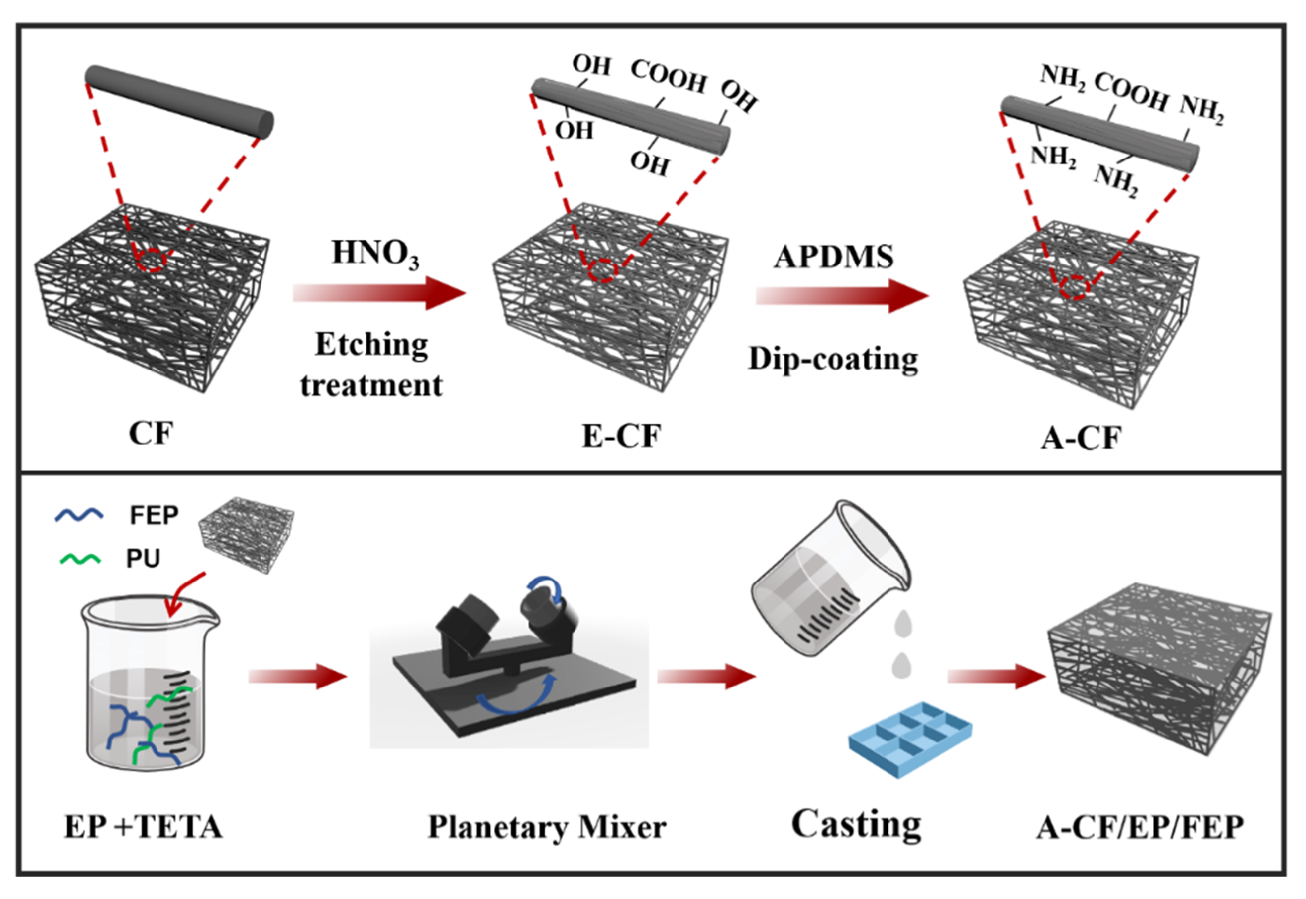
2.2. Chemical Etching of Carbon Felt

The pristine CF was firstly washed with acetone or ethanol and distilled water to remove the impurities and then dried in an oven at 80 °C. Next, the dried CF was subjected to a concentrated nitric acid solution at 100 °C for 30 min. After washing with distilled water to be neutral and drying at 80 °C, the nitric-acid-etched carbon fiber was obtained, which was denoted as E-CF.

2.3. APDMS Modification of E-CF

APDMS (3.0 g) was dissolved in 100 mL of ethyl acetate and ultrasonicated (400 w) for 10 min. Then, the E-CF was soaked in the above solution with a water bath, heated at 60 °C for 30 min, and then oven-dried at 80 °C. Thereafter, APDMS-modified E-CF was obtained and denoted as A-CF.

2.4. Preparation of A-CF/EP/FEP Composites

The fabrication process of the A-CF/EP/FEP composites is illustrated in Figure 1. Certain amounts of the EP matrix, TETA (1 g of EP/0.1 g of hardener), FEP, and PU were mixed with a vacuum planetary mixer to form a homogenous phase using the vacuum-assisted assembly technique. After, the A-CF was immersed in the mixture and further vacuum-mixed. After curing at room temperature for 4 h and 80 °C for 3 h, A-CF/EP/FEP composites were successfully prepared. For comparison, EP/FEP, CF/EP/FEP, and E-CF/EP/FEP were also prepared using the same method.

2.5. Characterization

A Tensor 27 Fourier transform infrared (FTIR) spectrometer was used to detect the chemical compositions of the original, etched, and APDMS-modified carbon felt. The morphology was observed under a Quanta 200 scanning electron microscope (SEM). The WCA was measured by Contact Angle System (Theta lite, Sweden). Specifically, a water droplet (10 µL) was placed on the surface of a composite at room temperature. The contact angles and sliding angles were taken from five different positions of the composite surface, and the average values were determined. The thermal conductivity of the composites was measured with a TPS thermal conductivity meter (Setaram, France) according to the standard ISO 22007-2:2015-09. Heat transfer capacity as the function time of the composites was recorded using an infrared thermograph (Fluke Ti480 Pro, USA).

2.6. Evaluation of Tribological Robustness

The tribological performance of the A-CF/EP/FEP composites was tested on an MPX-2000 pin-on-disk configuration friction and wear tester (Xuanhua Testing Factory, Zhangjiakou, China). The testing conditions included non-lubrication, applied load of 2.8 MPa, sliding speed of 0.51 m s−1, and room temperature (about 25 °C). Before each experiment, the pin was burnished with a 1000-grit SiC abrasive paper to reach a mean roughness of 0.15–0.3 μm. After washing with anhydrous ethanol, the pin was put into application. A FA2004N high-precision electronic balance with an accuracy of 0.1 mg was employed to weigh the samples. To obtain an accurate weight, all the samples were dried in an 80 °C oven for one hour before and after each test.
The wear rate of a sample was calculated as follows:
W r = Δ m ρ × F N × L
where Δm is the mass loss (g), ρ is the composite density (g·cm−3), FN is the vertical load (N), and L is the sliding distance of the pin (m).

3. Results and Discussion

3.1. Characteristics of the A-CF/EP/PEF Composites

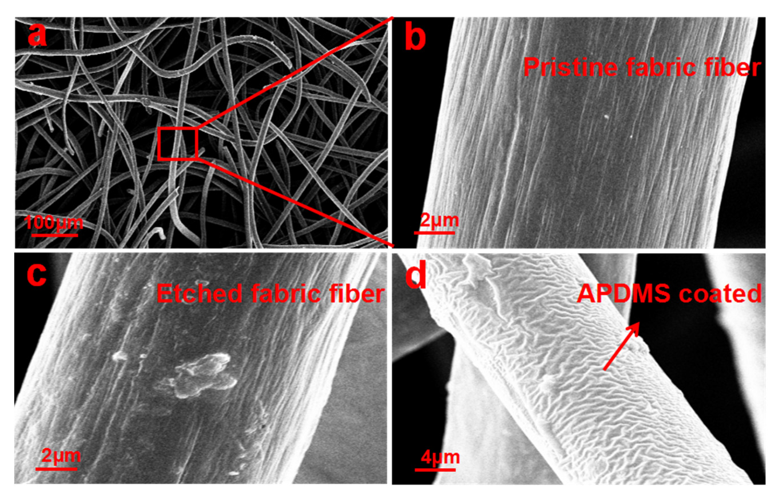
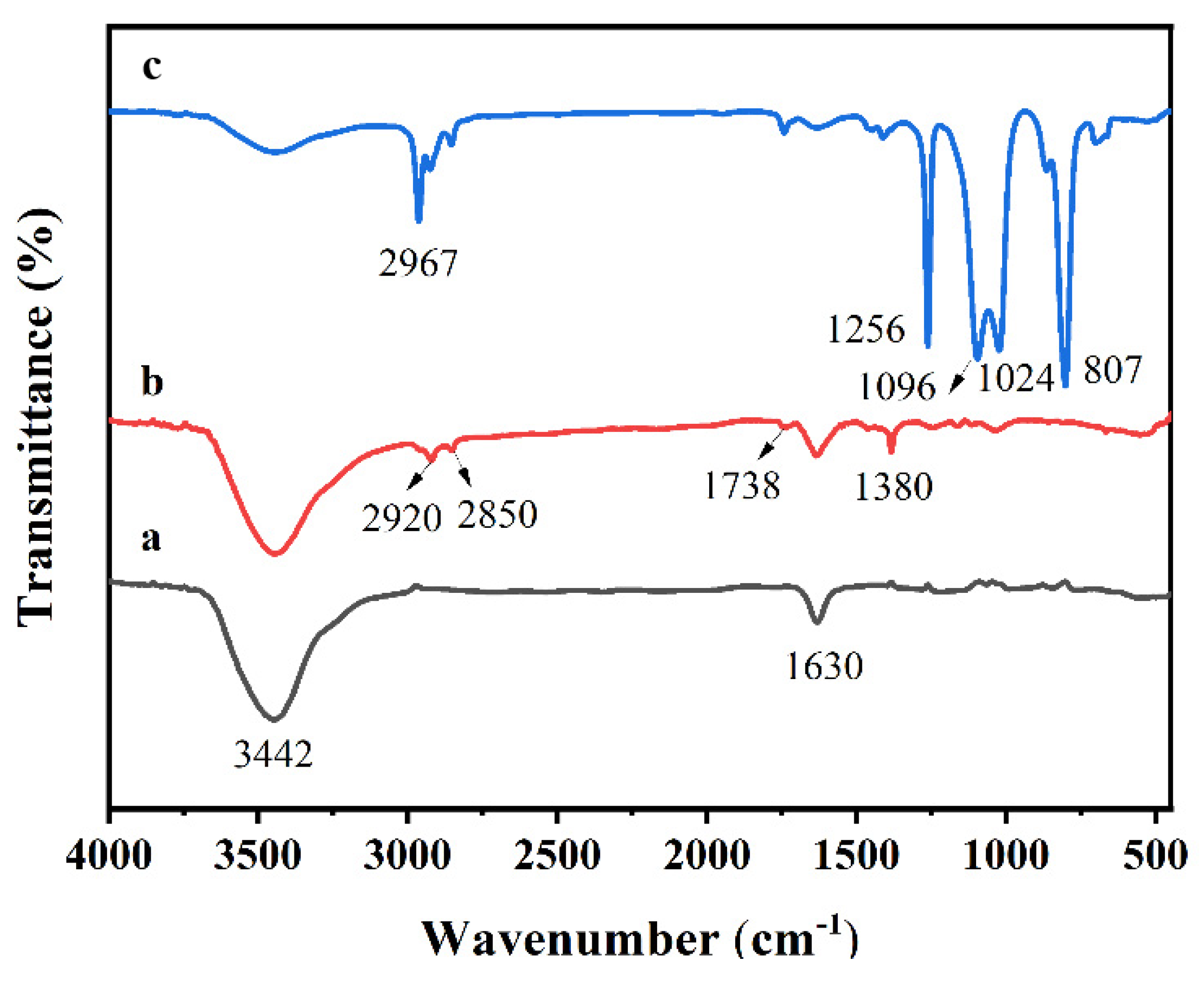
3.1.1. Modification of the Carbon Fiber

SEM images show that the pristine CF has a loose woven structure with gaps between fibers (Figure 2a,b), which provides the necessary space to form composites with EP. After chemical etching in the nitric acid solution (Figure 2c), the surface of CF became rough. This rough structure is conducive to enlarging the surface area and improving the bonding strength of resin with CF. On this foundation, after the APDMS modification of CF (A-CF, Figure 2d), the E-CF is wrapped in a thin wrinkled film, which will reinforce the strength between the inorganic CF and the organic EP [27]. In another word, the A-CF shall be very compatible with organics, such as EP.
The FTIR spectra of CF, E-CF, and A-CF are shown in Figure 3. Obviously, the stretching vibration peaks of -OH and C=C appear in CF at about 3442 and 1630 cm−1, respectively (Figure 3a). In addition to these two peaks, the spectrum of E-CF (Figure 3b) shows new peaks at 2920, 2850, and 1380 cm−1 corresponding to the stretching vibration of -CH2 and -CH3, and an apparent peak at 1738 cm−1 assigned to the C=O stretching vibration of ester groups (-COOR) that originates from nitrate-acid-etched CF [28]. The spectrum of A-CF (Figure 3c) shows a new peak of -CH at 2967 cm−1 from APDMS, and the peaks of -CH2 and -CH3 at 2920 and 2850 are more intense than those of E-CF and A-CF. In addition, the sharp peaks at 1256 and 807 cm−1 stand for Si-CH3. The main broad band from about 880 to 1190 cm−1 is attributed to Si-O-C, and the bands at 1096 and 1024 cm−1 are assigned to Si-O-Si. All these results confirm the introduction of APDMS to the carbon fiber surface.

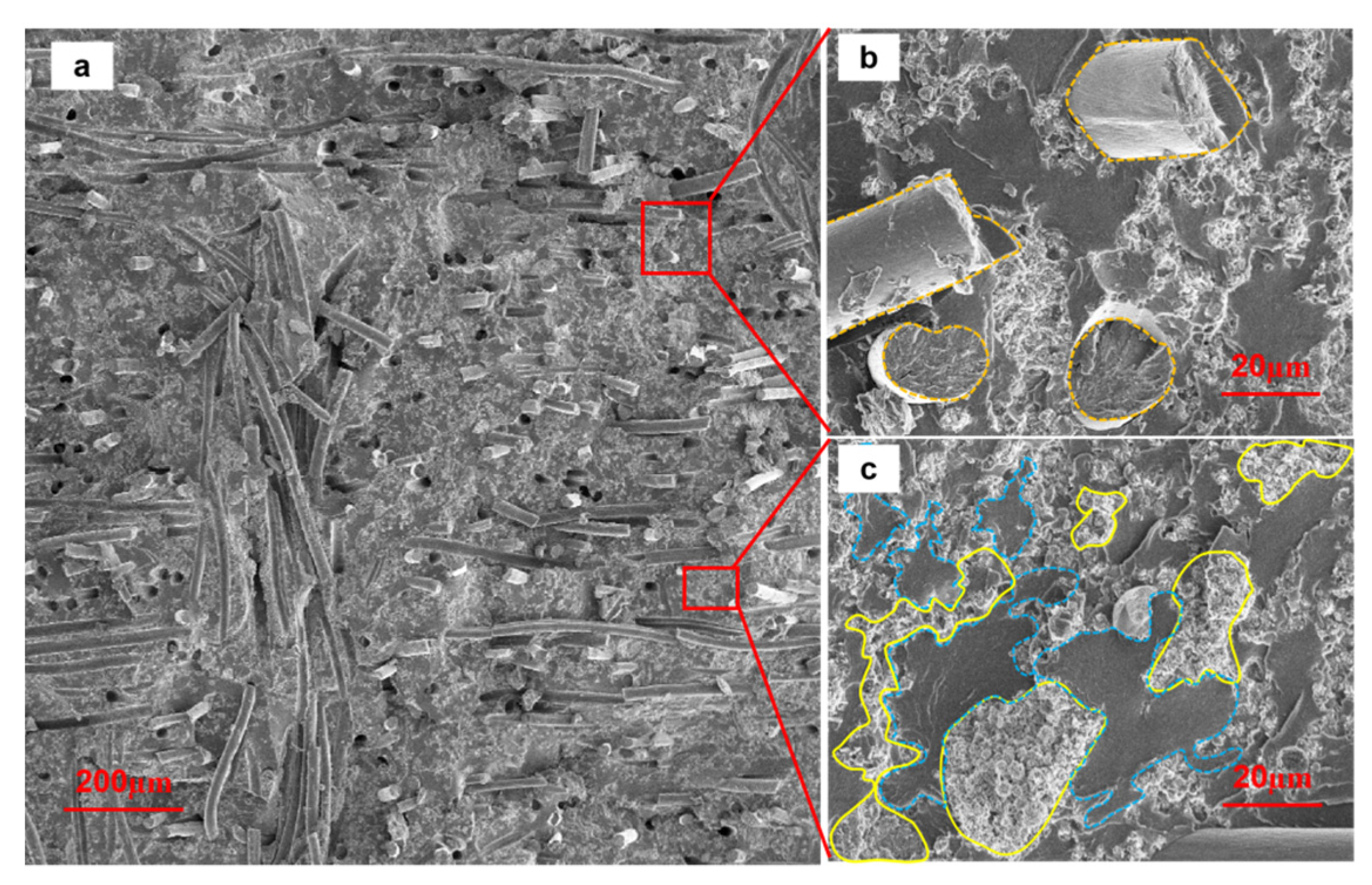
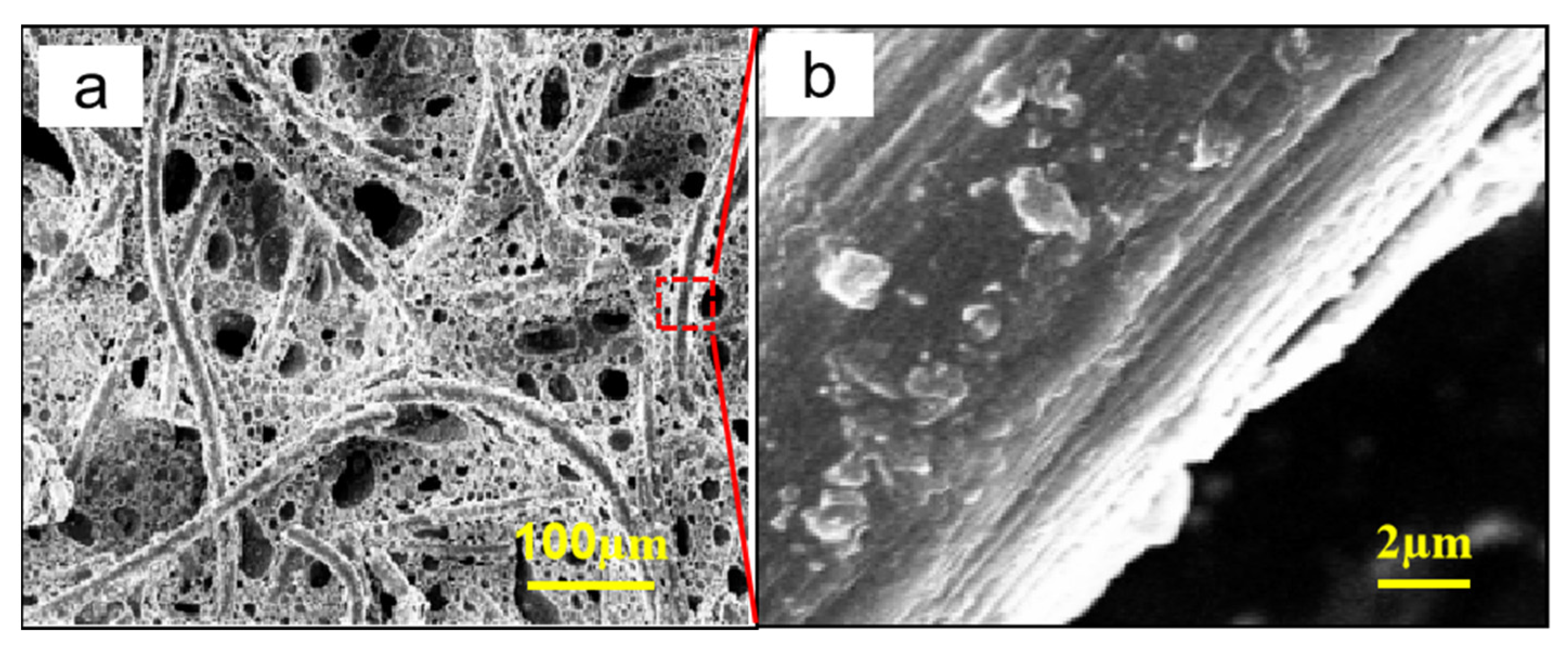
3.1.2. Morphology of the A-CF/EP Composites

The cross-section morphology and microstructure of the A-CF/EP/PEF composites are shown in Figure 4. Clearly, the hierarchical structure constructed jointly by the EP/FEP composite, the filler A-CF, and the low-surface-energy FEP creates a hydrophobic surface. A good interpenetrating structure is formed between the resin and the filler, and the matrix is uniformly dispersed in A-CF/EP/PEF (Figure 4a). On the one hand, carbon fibers just act as “grasses” planted firmly in the “soil” of the resin matrix (Figure 4b), and the two are closely combined. On the other hand, the EP with good adhesion and the FEP with low surface energy are well mixed (Figure 4c). Areas of different colors in Figure 4c are interspersed with each other, and the interface between the two is well combined.

3.2. Wettability of the A-CF/EP/FEP Composites

FEP is a low-surface-energy material, and its content affects the wettability of A-CF/EP/FEP composites. The WCAs of A-CF/EP/FEP composites with 10–50 wt% FEP is shown in Table 1. Obviously, all the A-CF/EP/FEP composites are hydrophobic, and the WCAs exceed 90°. The WCA increases firstly and then decreases with the rise in FEP content, with a maximum of 109.9 ± 2.6° at the FEP content of 20 wt%. Owing to the low surface energy of FEP, the hydrophobicity of the A-CF/EP/FEP composites shall be improved with the increasing FEP content, but this does not seem true, which brings us to the combination among EP, FEP, and the A-CF fillers.
Figure 5a shows obvious holes in the A-CF/EP/FEP composites at higher FEP content (50 wt%), which is mainly due to the gap between the resin phase (EP, FEP) and the filler (Figure 5b). In other words, excessive FEP is unfavorable for the hydrophobicity of M-CF/EP composites. The content of the low-surface-energy FEP plays an important role in the construction of the hydrophobic surface, and 20 wt% FEP is confirmed as the best content.

3.3. Wear Resistance of the A-CF/EP/FEP Composites

3.3.1. Effect of FEP on the Wettability of A-CF/EP/FEP Composites

The wear rates of A-CF/EP composites containing 2%, 4%, and 6% PU were studied under the applied load of 2.8 MPa and the sliding speed of 0.51 m·s−1. In the continuous friction tests, the wear rates of A-CF/EP composites at a certain abrasion cycle decreased with the increase in PU content (Table 1). At the abrasion cycle of 30 kilo times, the wear rates of A-CF/EP composites with 2.0%, 4.0%, and 6.0% PU are 1.42, 1.19, and 0.91 × 10⁻¹³·m3·N−1·m−1, respectively, indicating that the wear rate of the composites decreases with the increase in PU content. When the number of cycles increases to 60, 90, and 120 kilo times, the wear rates of the A-CF/EP composites still conform to the above rule. Compared with the other two composites, the A-CF/EP composite with 6% PU always shows a slower wear rate in the same wear cycle, indicating that PU has an indelible effect on improving the tribological properties of the composites. After 120 kilo cycles of abrasion, the wear rate of the A-CF/EP composite with 6 wt% PU is only 0.58 × 10⁻¹³ m3·N−1·m−1, which further proves the wear-resistance stability of PU-containing composites. In addition, the friction coefficient of the A-CF/EP composites was also investigated. The last column of Table 2 shows that the friction coefficient decreases slightly with the increase in PU, which proves the significance of PU to the tribological properties of the A-CF/EP composites.

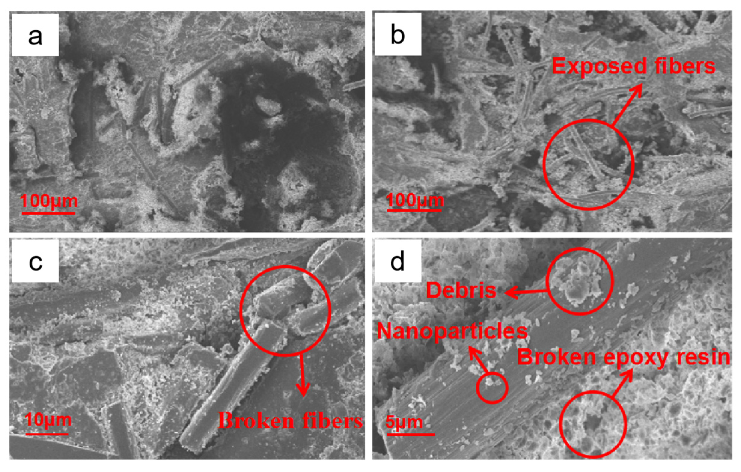
3.3.2. Mechanistic Analysis

Low strength is a common problem of hydrophobic surfaces and limits the application of hydrophobic products under actual working conditions. Why the A-CF/EP/FEP composites possess excellent hydrophobicity and wear resistance at the same time shall be explained from the structural and compositional perspectives. On the one hand, the combination of A-CF and EP/FEP provides micro-nano structures for the formation of hydrophobic surfaces (Figure 4a). On the other hand, the FEP offers low surface energy to contain fluorine, and the combination of FEP and EP provides good adhesion (Figure 4) to the filler (A-CF). Moreover, the good combination of the filler and resins is the premise of excellent properties of composites. The surface morphology of the A-CF/EP/FEP composites after wearing was analyzed to explain the reason for their continuous hydrophobicity. After 60,000 wear cycles, some epoxy resins were damaged, and the composite surface remained relatively intact (Figure 6a). In addition, there is no obvious gap between the filler (A-CF) and resins (EP/FEP), indicating that A-CF has good interfacial adhesion. When the wear cycle increased to 120,000 times (Figure 6b), severe continuous friction aggravated the damage to EP and subjected a large number of carbon fibers to exposure and fracturing (Figure 6c,d). At the same time, the remaining debris and nanoparticles attached to the carbon fiber (Figure 6d) ensure the micro-nano structure required by the hydrophobic surface. Both intact and broken carbon fibers can provide low friction resistance in the friction process, which is related to the high wear resistance of carbon materials and the slender morphology of fibers.

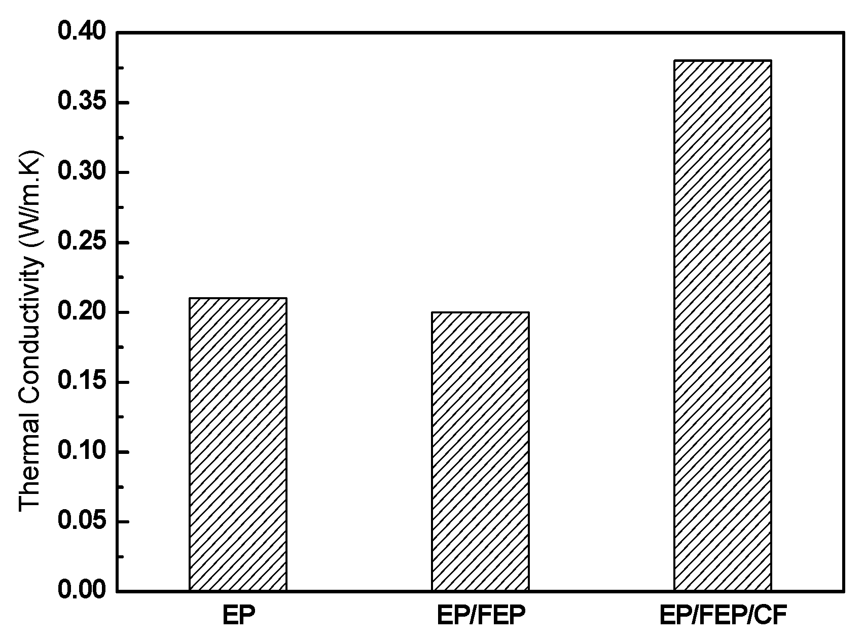
3.4. Thermal Conductivity of A-CF/EP/FEP Composites

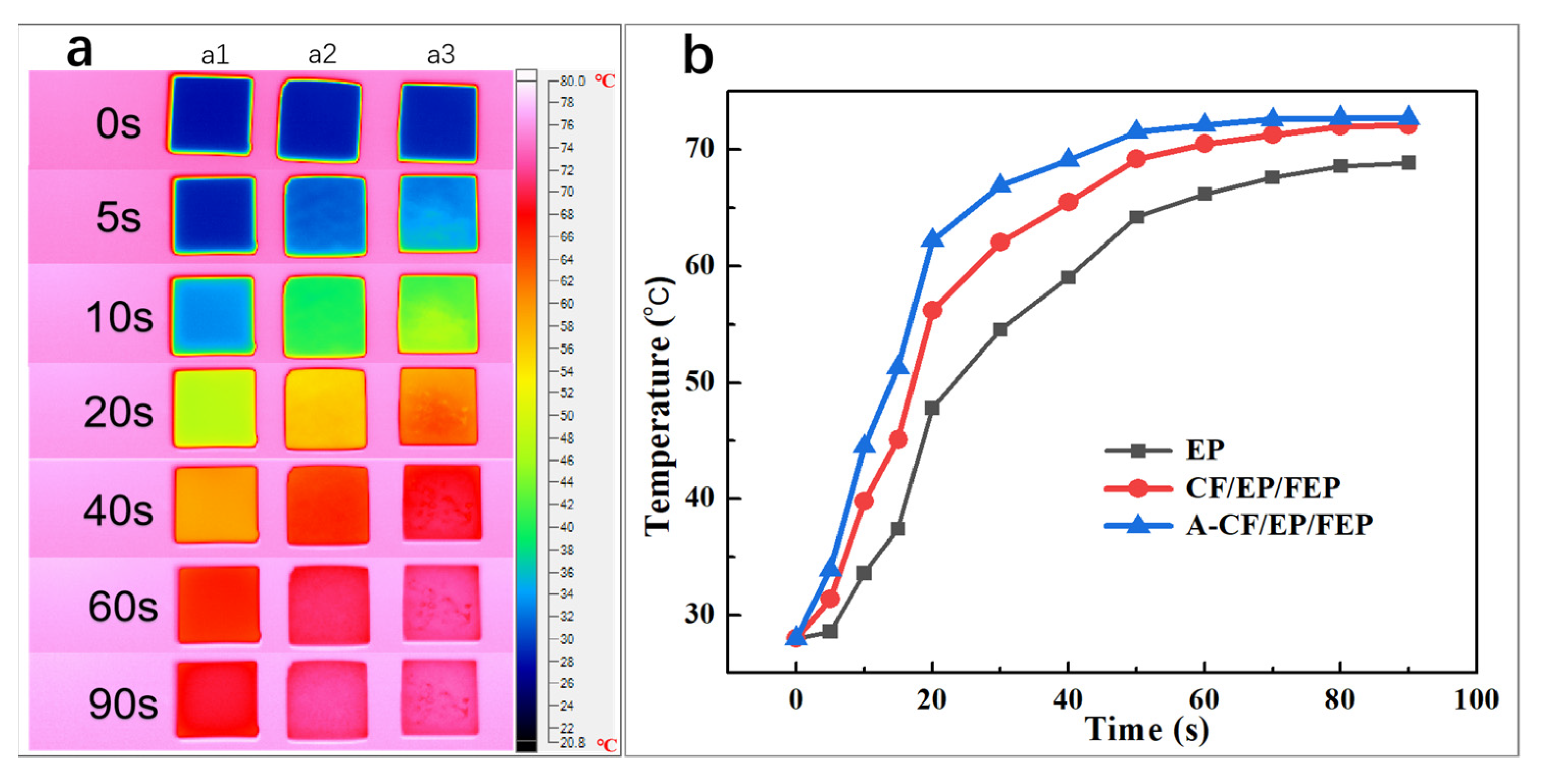
3.4.1. Effect of A-CF on Thermal Conductivity of A-CF/EP/FEP Composites

The TCs of pure EP, EP/FEP, and A-CF/EP/FEP were measured at room temperature (Figure 7). Like in other reports [29,30], the TC of pure EP is 0.21 W/(m·K). When 20% FEP was added into EP, the TC of the EP/FEP composite did not obviously change. On the contrary, TC decreased slightly to 0.19 W/(m·K). After A-CF was added to EP/FEP composites, the TC increased significantly to 0.38 W/(m·K) when the FEP content was 20%, which is 1.81 and 2.0 times those of the pure EP and the EP/FEP composite, respectively. The formation of an effective heat conduction path in materials such as EP and EP/FEP composites is a necessary condition for heat conduction, which will benefit phonon transmission. For the A-CF/EP/FEP, the presence of A-CF contributes to the formation of a good heat conduction network.
To visually evaluate the heat absorption capacity of samples, we recorded the infrared thermal images and the corresponding surface temperature changes in EP (a1), EP/FEP (a2), and A-CF/EP/FEP (a3) during the heating process. To ensure uniform and consistent temperatures, we placed all the composites on a heating plate and maintained room temperature or 80 ± 2 °C for 1 h. During the heating (Figure 8a), the surface colors changed the fastest in A-CF/EP/FEP composites and the slowest in EP. In particular, the A-CF/EP/FEP composite rose from low temperature (blue) to high temperature (light pink) in the shortest time (Figure 8a). The endothermic efficiency of the samples is shown in Figure 8b. Clearly, when the heating time was 20 s, the surface temperatures of EP, EP/FEP, and A-CF/EP/FEP were 47.7, 55.9, and 62.2 °C, respectively. The A-CF/EP/FEP composite has a higher thermal management and heat transfer capacity compared with EP and EP/FEP.

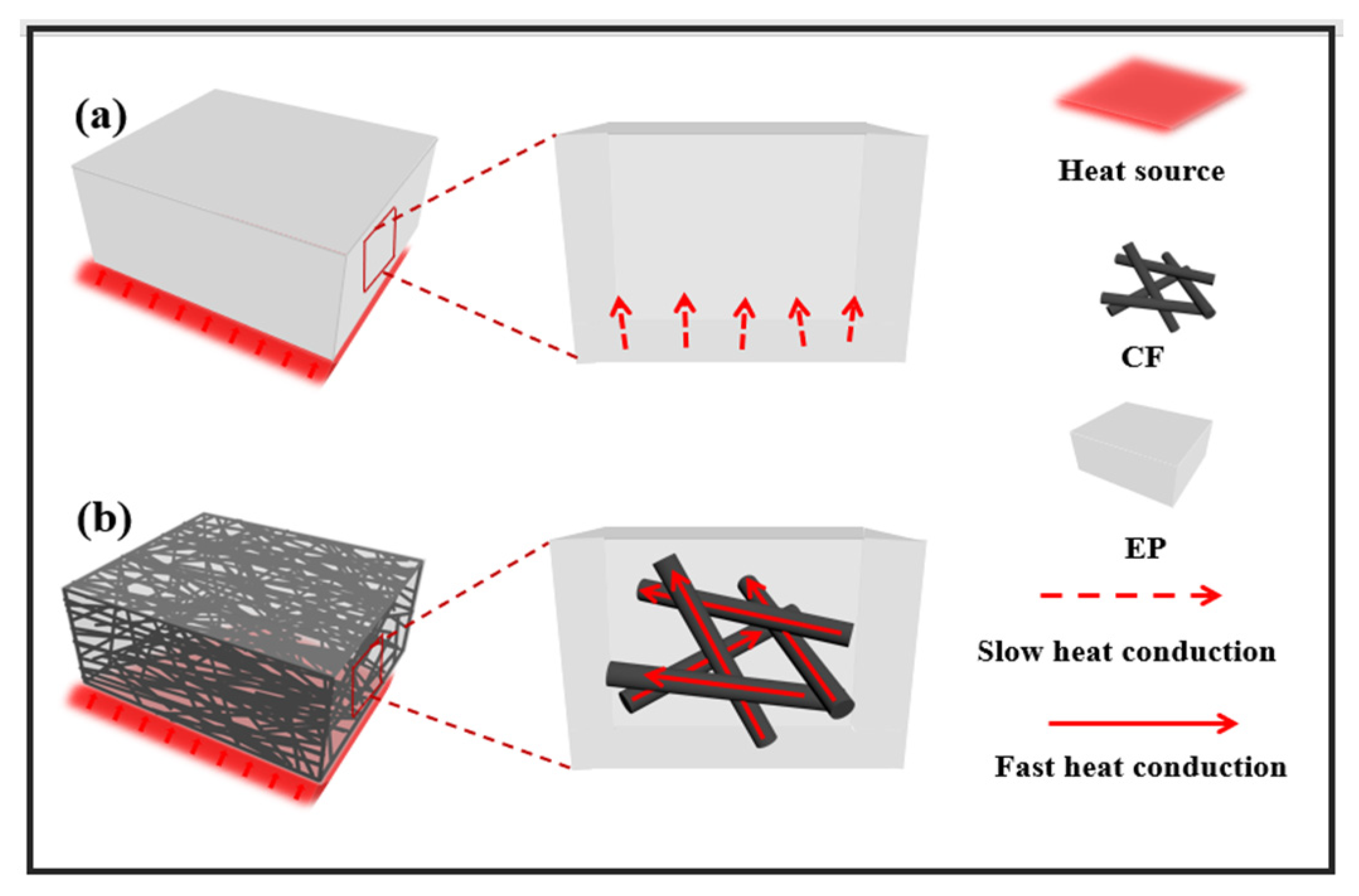
3.4.2. Mechanistic Analysis

The improvement in thermal conductivity in the A-CF/EP/FEP composites is attributed to the existence of A-CF. A schematic of thermal conduction is shown in Figure 9. As for the EP/FEP composites, heat transfers slowly in the polymer matrix (Figure 9a) owing to the low thermal conductivity of EP and FEP, and the high thermal resistance at the EP and FEP interface. Therefore, the heat transfer performance of EP/FEP composites is not improved significantly from that of EP. For the A-CF/EP/FEP composites (Figure 9b), the A-CF framework provides a dense and regular network for phonon transmission during heat conduction, which not only greatly reduces the thermal resistance between the carbon fibers and resins, but also enhances the composites. Obviously, the fast heat conduction route formation can provide A-CF/EP/FEP composites with excellent thermal conductivity.

4. Conclusions

Composites with wear resistance, high thermal conductivity, and hydrophobicity were successfully prepared from EP/FEP and APDMS-modified carbon fiber (A-CF). The A-CF/EP/FEP composites have hydrophobicity from the low-surface-energy FEP, good adhesion from EP, and improved wear resistance and thermal conductivity from A-CF. When the PU is added to the A-CF/EP/FEP composites, the tribological properties are improved significantly. When the FEP content is 20 wt%, the WCA of A-CF/EP/FEP composites maximizes to 109.9 ± 2.6°. The low surface energy of FEP helps maintain continuous hydrophobicity in the A-CF/EP/FEP composites. The residual debris and nanoparticles attached to the carbon fiber after wearing ensure the micro-nano structure required by hydrophobic surfaces. With the addition of A-CF, the TC of A-CF/EP/FEP composites containing 20% FEP increases significantly to 0.38 W/(m·K), which is 1.81 and 2.0 times those of pure EP and EP/FEP composites, respectively. In conclusion, the A-CF framework not only provides a dense and regular network for phonon transmission in reducing the thermal resistance between the carbon fibers and resins but also enhances the wear resistance of the A-CF/EP/FEP composites. The A-CF/EP/FEP composites possess high wear resistance, hydrophobicity, and thermal conductivity. Thus, this study provides a new and simple way to prepare composite materials.

Author Contributions

H.H. contributed to the conceptualization; H.H. and Y.C. carried out part of the experimental work; Z.F. were responsible for the developed methodology; S.W. and Y.D. validated the experiments; F.L. contributed to data analysis and interpretation; the original draft was prepared by H.H. and Y.Z.; reviewing and editing of the manuscript was carried out by Y.C. and Y.Z.; Y.Z. was responsible for supervision and funding. All authors have read and agreed to the published version of the manuscript.

Funding

This work is supported by the Research on Key Techniques in Reliability of Low Power Sensor Chip for IOTIPS (5700-202041397A-0-0-00), and the technology project of headquarters, State Grid Corporation of China.

Institutional Review Board Statement

Not applicable.

Informed Consent Statement

Not applicable.

Data Availability Statement

Not applicable.

Conflicts of Interest

The authors declare no conflict of interest.

References

  1. Han, Y.; Shi, X.; Yang, X.; Guo, Y.; Zhang, J.; Kong, J.; Gu, J. Enhanced thermal conductivities of epoxy nanocomposites via incorporating in-situ fabricated heterostructured SiC-BNNS fillers, Compos. Sci. Technol. 2020, 187, 107944. [Google Scholar] [CrossRef]
  2. Liu, Z.; Zhang, C.; Jing, J.; Zhang, X.; Wang, C.; Liu, F.; Jiang, M.; Wang, H. Bristle worm inspired ultra-durable superhydrophobic coating with repairable microstructures and anti-corrosion/scaling properties. Chem. Eng. J. 2022, 436, 135273. [Google Scholar] [CrossRef]
  3. Pelto, J.; Heino, V.; Karttunen, M.; Rytöluoto, I.; Ronkainen, H. Tribological performance of high density polyethylene (HDPE) composites with low nanofiller loading. Wear 2020, 460, 203451. [Google Scholar] [CrossRef]
  4. Ma, X.; Wang, W.; Qi, X.; Yang, J.; Lei, Y.; Wang, Y. Highly thermally conductive epoxy composites with anti-friction performance achieved by carbon nanofibers assisted graphene nanoplatelets assembly. Eur. Polym. J. 2021, 151, 110443. [Google Scholar] [CrossRef]
  5. Liang, C.B.; Qiu, H.; Han, Y.Y.; Gu, H.B.; Song, P.; Wang, L.; Kong, J.; Cao, D.P.; Gu, J.W. Superior electromagnetic interference shielding 3D graphene nanoplatelets/reduced graphene oxide foam/epoxy nanocomposites with high thermal conductivity. J. Mater. C 2019, 7, 2725–2733. [Google Scholar] [CrossRef]
  6. Zhang, Z.; Qu, J.; Feng, Y.; Feng, W. Assembly of graphene-aligned polymer composites for thermal conductive applications. Compos. Commun. 2018, 9, 33–41. [Google Scholar] [CrossRef]
  7. Jiang, F.; Cui, S.Q.; Rungnim, C.; Song, N.; Shi, L.Y.; Ding, P. Control of a dual-crosslinked boron nitride framework and the optimized design of the thermal conductive network for its thermoresponsive polymeric composites. Chem. Mater. 2019, 31, 7686–7695. [Google Scholar] [CrossRef]
  8. Li, L.; Bai, Y.; Li, L.; Wang, S.; Zhang, T. A superhydrophobic smart coating for flexible and wearable sensing electronics. Adv. Mater. 2017, 29, 1702517. [Google Scholar] [CrossRef]
  9. Sam, E.K.; Sam, D.K.; Lv, X.; Liu, B.; Xiao, X.; Gong, S.; Yu, W.; Chen, J.; Liu, J. Recent development in the fabrication of self-healing superhydrophobic surfaces. Chem. Eng. J. 2019, 373, 531–546. [Google Scholar] [CrossRef]
  10. Qian, H.; Xu, D.; Du, C.; Zhang, D.; Li, X.; Huang, L.; Deng, L.; Tu, Y.; Mol, J.M.C.; Terryn, H.A. Dual-action smart coatings with a self-healing superhydrophobic surface and anti-corrosion properties. J. Mater. Chem. A 2017, 5, 2355–2364. [Google Scholar] [CrossRef] [Green Version]
  11. Youn, D.-H.; Lee, K.-S.; Jung, S.-K.; Kang, M. Fabrication of a simultaneous highly transparent and highly hydrophobic fibrous films. Appl. Sci. 2021, 11, 5565. [Google Scholar] [CrossRef]
  12. Shayesteh, H.; Norouzbeigi, R.; Rahbar-Kelishami, A. Hydrothermal facile fabrication of superhydrophobic magnetic nanospiky nickel wires: Optimization via statistical design. Surf. Interfaces 2021, 26, 101315. [Google Scholar] [CrossRef]
  13. Shen, L.; Qiu, W.; Wang, W.; Xiao, G.; Guo, Q. Facile fabrication of superhydrophobic conductive graphite nanoplatelet/vapor-grown carbon fiber/polypropylene composite coatings, Compos. Sci. Technol. 2015, 117, 39–45. [Google Scholar] [CrossRef]
  14. Hsu, C.-P.; Chang, L.-Y.; Chiu, C.-W.; Lee, P.T.C.; Lin, J.-J. Facile fabrication of robust superhydrophobic epoxy film with polyamine dispersed carbon nanotubes. ACS Appl. Mater. Inter. 2013, 5, 538–545. [Google Scholar] [CrossRef] [PubMed]
  15. Ellinas, K.; Gogolides, E. Ultra-low friction, superhydrophobic, plasma micro-nanotextured fluorinated ethylene propylene (FEP) surfaces. Micro. Nano. Eng. 2022, 14, 100104. [Google Scholar] [CrossRef]
  16. Liu, Z.; Ren, L.; Jing, J.; Wang, C.; Liu, F.; Yuan, R.; Jiang, M.; Wang, H. Fabrication of robust superhydrophobic organic-inorganic hybrid coating through a novel two-step phase separation method. Prog. Org. Coat. 2021, 157, 106320. [Google Scholar] [CrossRef]
  17. Wang, H.; Wang, R.; Tao, R.; Zhu, Y.; Lv, C.; Zhu, Y. Fabrication of superhydrophobic fiber fabric/epoxy composites coating on aluminum substrate with long-lived wear resistance. RSC Adv. 2016, 98, 95556–95563. [Google Scholar] [CrossRef]
  18. Zhang, F.; Feng, Y.; Feng, W. Three-dimensional interconnected networks for thermally conductive polymer composites: Design, preparation, properties, and mechanisms. Math. Sci. Eng. R 2020, 142, 100580. [Google Scholar] [CrossRef]
  19. Guo, Y.; Ruan, K.; Shi, X.; Yang, X.; Gu, J. Factors affecting thermal conductivities of the polymers and polymer composites: A review, Compos. Sci. Technol. 2020, 193, 108134. [Google Scholar] [CrossRef]
  20. Kim, G.H.; Lee, D.; Shanker, A.; Shao, L.; Kwon, M.S.; Gidley, D.; Kim, J.; Pipe, K.P. High thermal conductivity in amorphous polymer blends by engineered interchain interactions. Nat. Mater. 2015, 14, 295–300. [Google Scholar] [CrossRef]
  21. Gu, J.W.; Liang, C.B.; Zhao, X.M.; Gan, B.; Qiu, H.; Guo, Y.Q.; Yang, X.T.; Zhang, Q.Y.; Wang, D.Y. Highly thermally conductive flame-retardant epoxy nanocomposites with reduced ignitability and excellent electrical conductivities. Compos. Sci. Technol. 2017, 139, 83–89. [Google Scholar] [CrossRef]
  22. Xu, F.; Cui, Y.; Bao, D.; Lin, D.; Yuan, S.; Wang, X.; Wang, H.; Sun, Y. A 3D interconnected Cu network supported by carbon felt skeleton for highly thermally conductive epoxy composites. Chem. Eng. J. 2020, 388, 124287. [Google Scholar] [CrossRef]
  23. Le, T.X.H.; Bechelany, M.; Cretin, M. Carbon felt based-electrodes for energy and environmental applications: A review. Carbon 2017, 122, 564–591. [Google Scholar] [CrossRef]
  24. He, P.; Jia, L.; Ma, G.; Wang, R.; Yuan, J.; Duan, X.; Yang, Z.; Jia, D. Effects of fiber contents on the mechanical and microwave absorbent properties of carbon fiber felt reinforced geopolymer composites. Ceram. Int. 2018, 44, 10726–10734. [Google Scholar] [CrossRef]
  25. Ma, J.; Shang, T.; Ren, L.; Yao, Y.; Zhang, T.; Xie, J.; Zhang, B.; Zeng, X.; Sun, R.; Xu, J.-B.; et al. Through-plane assembly of carbon fibers into 3D skeleton achieving enhanced thermal conductivity of a thermal interface material. Chem. Eng. J. 2020, 380, 122550. [Google Scholar] [CrossRef]
  26. Houa, X.; Chena, Y.; Dai, W.; Wang, Z.; Li, H.; Lin, C.; Nishimurad, K.; Jiang, N.; Yu, J. Highly thermal conductive polymer composites via constructing microphragmites communis structured carbon fibers. Chem. Eng. J. 2019, 375, 121921. [Google Scholar] [CrossRef]
  27. Song, W.; Gu, A.; Liang, G.; Yuan, L. Effect of the surface roughness on interfacial properties of carbon fibers reinforced epoxy resin composites. Appl. Surf. Sci. 2011, 257, 4069–4074. [Google Scholar] [CrossRef]
  28. Chen, L.; Yuan, S.; Wang, H.; Zhu, Y.; Fu, D.; Li, Z. Spherical Polydopamine-Modified Carbon-Felt Cathode with an Active Indole Structure for Efficient Hydrogen Peroxide Electroproduction. Appl. Sci. 2021, 11, 5371. [Google Scholar] [CrossRef]
  29. Zhang, M.; Ma, W.; Cui, J.; Wu, S.; Han, J.; Zou, Y.; Huang, C. Hydrothermal synthesized UV-resistance and transparent coating composited superoloephilic electrospun membrane for high efficiency oily wastewater treatment. J. Hazard. Mater. 2020, 383, 121152. [Google Scholar] [CrossRef]
  30. Cui, L.-J.; Geng, H.-Z.; Wang, W.-Y.; Chen, L.-T.; Gao, J. Functionalization of multi-wall carbon nanotubes to reduce the coefficient of the friction and improve the wear resistance of multi-wall carbon nanotube/epoxy composites. Carbon 2013, 54, 277–282. [Google Scholar] [CrossRef]
Figure 1. Schematic of the fabrication process of the A-CF/EP/FEP composites.
Applsci 12 09363 g001
Figure 2. SEM images of pristine CF (a,b), E-CF (c), and A-CF (d).
Applsci 12 09363 g002
Figure 3. FTIR spectra of CF (a), E-CF (b), and A-CF (c).
Applsci 12 09363 g003
Figure 4. Morphology of the hydrophobic A-CF/EP/PEF surface (a), the combination of carbon fiber and EP/FEP resin (b), and incorporation between EP and FEP (c).
Applsci 12 09363 g004
Figure 5. Morphology of the A-CF/EP/FEP composite with 50% FEP.
Applsci 12 09363 g005
Figure 6. Surface SEM images of the A-CF/EP composites after 60,000 (a) and 120,000 (bd) abrasion cycles at different magnifications.
Applsci 12 09363 g006
Figure 7. Thermal conductivity of pure EP, EP/FEP, and A-CF/EP/FEP composites with 20% FEP and 4% PU.
Applsci 12 09363 g007
Figure 8. Infrared thermal images (a) and surface temperature variation with time (b) elapse of EP (a1), CF/EP/FEP (a2), and A-CF/EP/FEP (a3) composites during heating processes.
Applsci 12 09363 g008
Figure 9. Schematic illustration of the heat conduction in the EP (a) and A-CF/EP/FEP (b) composites.
Applsci 12 09363 g009
Table 1. Water contact angle (WCA) of M-CF/EP composites with 4% PU and different contents of FEP.
Sample InformationWater Contact Angle/°
10% FEP + 4% PU95.8 ± 2.0°
20% FEP + 4% PU109.9 ± 2.6°
30% FEP + 4% PU107.3 ± 1.0°
40% FEP + 4% PU108.9 ± 3.2°
50% FEP + 4% PU103.8 ± 1.8°
Table 2. Wear rates (10−13·m3·N−1·m−1) and friction coefficients of the M-CF/EP composites with different contents of PU under the applied load of 2.8 MPa and sliding speed of 0.51 m s−1.
SamplesWear Rate Changes with Abrasion Cycles/TimesFriction Coefficient
30,00060,00090,000120,000
A-CF/EP with PU of 2.0%1.42 × 10−131.21 × 10−131.92 × 10−130.72 × 10−130.398
A-CF/EP with PU of 4.0%1.19 × 10−131.07 × 10−130.86 × 10−130.67 × 10−130.363
A-CF/EP with PU of 6.0%0.91 × 10−130.82 × 10−130.62 × 10−130.58 × 10−130.318
Publisher’s Note: MDPI stays neutral with regard to jurisdictional claims in published maps and institutional affiliations.

