Article

Development of an Estimation Method for Depth of Spalling Damage in Concrete Pavement by Ultrasonic Velocity Measurement

Department of Transportation Engineering, Myongji University, Yongin 17058, Korea
*
Author to whom correspondence should be addressed.
Submission received: 30 August 2022 / Revised: 22 September 2022 / Accepted: 27 September 2022 / Published: 30 September 2022
(This article belongs to the Special Issue Fatigue, Performance, and Damage Assessment of Concrete)

Abstract

:
As the amount of aged pavement increases, functional damage, such as spalling, occurs frequently on Portland Cement Concrete pavement (PCC) in South Korea. However, the existing management method does not properly reflect the scope of deterioration of the pavement causing early damage. To overcome the problem of the existing repair method, this study evaluated the deterioration of functional damage on the surface of the slab as soundness through ultrasonic velocity measurement method among non-destructive testing (NDT) techniques and suggested a method to estimate the depth of deterioration. To develop a method for estimating the depth of the deterioration a slab, a preliminary investigation was conducted to check the range of ultrasonic velocity of concrete pavement in South Korea and to evaluate the variability of NDT equipment. Based on the ultrasonic velocity, the sound rating of concrete pavement was graded from 5 for “very good” to 0 for “very poor”, and the tendency of the ultrasonic velocity to increase according to the depth of the deteriorated areas was confirmed.

1. Introduction

Due to aging, environmental problems, and management methods, the surface of Portland Cement Concrete pavement (PCC) in South Korea frequently is damaged, and the number of lawsuits for repairs and accidents is increasing every year. In South Korea, the total length of roads paved with concrete is 11,375 km, accounting for about 13% of the total ratio, and about 97% of expressway pavement consists of jointed plain concrete pavement [1]. In addition, the performance of aged pavement over 20 years is 1150 km/lane as of 2015, but it is expected to increase by a factor of 5.8 in 10 years to 6662 km/lane [2]. Therefore, the acceleration of the deterioration of the pavement and the damage that may occur due to the increase in aging cause problems in road users’ driving comfort and safety, along with an increase in repair costs. The Korea Expressway Corporation (KEC) in South Korea investigates the types of road damage, such as cracks, patching, scaling, edge distresses, damage on concrete durability, pop-out, and spalling damage, and the investigation showed that about 92 percent of the types of damage to the pavement occurred in joints [3]. Therefore, the maintenance of the older concrete pavement generally is managed by applying partial depth repair and bonded concrete overlay methods for spalling damage [4]. In particular, when spalling appears extensively in the pavement section, deterioration may occur inside the slab, especially in the spalling, and the risk of re-repair can be reduced by accurately investigating the range and depth of the damage. In the case of spalling damage, the asphalt patching and the damaged area can be removed from the rapid setting and partial depth repair can be done with concrete material, considering the severity of the damage and the field environment. In the case of asphalt patching performed in a rapid setting, since the deterioration of pavement propagates from the slab surface is not removed around the spalling damage part, re-repair occurs from the part. If traffic closure conditions are available, the deteriorated range of the pavement must be cut to a certain thickness and repaired [5]. In the case of partial depth repair, a sound radiation method can be used to estimate internal damage by striking steel bars, chains, etc. [6]. In the case of an overlay in concrete pavement, an existing road pavement layer is overlaid after cutting 5 cm [7].
However, the existing methods for evaluating the condition of the pavement for partial depth repair, visual inspection, and auditory inspection rely on the experience of practitioners to evaluate the condition of the pavement qualitatively. This method of repair is irregular, and early damage is occurring in some sections [5]. In particular, it is necessary to verify the effectiveness of the method because the existing adhesive concrete overlay method, which is applied after cutting 5 cm, is a uniform method based on experience rather than a quantitative design method according to the deterioration of the existing pavement.
According to a study that compared and analyzed the service life of the overlay where the existing pavement condition was reflected in the overlay design method compared in South Korea and the United States, the section where the Pavement Condition Index (PCI) limits were observed in the design lifespan of 10 years or less. Two out of 22 sections in the United States and 5 out of 10 sections in South Korea were observed [7]. The reasons that sections in which the pavement in South Korea was repaired failed to reach the design life are complex, but it is expected that the problem of cutting 5 cm all at once without reflecting the deterioration of the existing road pavement layer was a major factor. Therefore, in order to reduce the risk of having to repair the roads after a brief period of usage and maintain the road pavement function satisfying the design life after repair, a method to quantify the condition of existing concrete pavement is needed. Although the road pavement survey conducted mainly in South Korea provides information on the overall aging and support of road pavement through visual examination, Falling Weight Deflectometer (FWD) test, and strength tests of core specimens, it is difficult to evaluate the degree and depth of deterioration in the damaged areas. Ultrasonic velocity measurement is a non-destructive test (NDT) device capable of evaluating the condition of the concrete by targeting topical sections, and it should focus more on defects in the uniformity and durability of the microstructure than on the strength of the slab. This may take into account various complex factors, including density, elasticity, homogeneity, voids, chemical damage, deterioration, and carbonation of concrete [8,9].
In this study, we propose to use the ultrasonic velocity measurement method to estimate the depth of deteriorated range from the slab surface propagation to the bottom by investigating and analyzing the ultrasonic velocity of the spalling fracture, which is the main fracture type of concrete pavement. In addition, the purpose of the test was also to derive an additional ultrasonic velocity soundness grade for concrete used for road pavement.

2. Materials and Methods

2.1. Materials

Concrete Pavement

In this study, in order to evaluate the ultrasonic velocity measurement range of general concrete pavement, two concrete specimens were made according to the mixing ratios specified in Table 1. In addition, we analyzed 23 expressway core specimens under 5 years of age that showed no signs of deterioration and 16 national highway core specimens over 8 years of age that showed no extensive wear of the slab section.
In order to analyze the depth of the deterioration, cores of concrete pavement on Line 42 and Line 19 in South Korea were collected and tested by an ultrasonic velocity test. From the 31 slabs where spalling damage was observed visually, core specimens were collected on the spalling damage surface as shown in Figure 1, and four additional cores were collected from the slabs where the distresses to the road pavement was not detected by the visual inspection. The cores used in the test are shown in Table 2.
In order to analyze the depth of the deterioration, the pavement of the section where the core was tested was an old section where extensive damage was confirmed, and there were no specific design resources left at the time of construction. The general design thickness of concrete pavement slabs in South Korea is 30 cm, and the corresponding items can be confirmed through core specimens. In the case of mixing ratio, M1 or M2 is expected to be used in Table 1.

2.2. Methods

2.2.1. Method of Ultrasonic Velocity Measurement

A non-destructive evaluation method using ultrasonic velocity measurements was used as a technique for characterizing defects and damage to materials by observing the scattering of ultrasonic waves. Generally, when the speed of the ultrasonic wave is high, the quality and continuity of the material are good, and, if the speed is slow, it can be determined that the concrete has many cracks and voids. The Ultrasonic Pulse Velocity (UPV) method generates ultrasonic waves on the concrete surface through a converter and records the generation and arrival time of the sound waves that pass through the material and are sensed by the receiver at the opposite end. If the distance between the two points is known, the velocity of the wave can be determined. The pulse velocity is determined by a simple Equation (1).
Pules   Velocity = Path   Length Transit   Time
The method used to measure the ultrasonic velocity is divided into indirect and direct methods, but the direct method was used exclusively in this study because of the variability problem of the measurement results. An ultrasonic irradiation device uses ACSA 1410 Pulsar to input the thickness of the core specimens at each measurement and records the average ultrasonic velocity measured three times into contact with both ends of the specimens, as shown in Figure 2.
The ultrasonic velocity range that corresponded to the general concrete quality “good” was reported between 3500 m/s and 4500 m/s in accordance with the relevant experimental results and national control standards (Table 3) [10,11,12,13,14,15].

2.2.2. Evaluation Method for Variability of NDT Equipment

Non-destructive testing techniques are known as methods for evaluating properties and soundness without destroying the target structure. However, many non-destructive testing methods that have been studied and presented have not been used extensively in the field. This is because the inherent measurement error of the non-destructive test technique reduces the reliability of the evaluation, making it difficult to understand the survey data. In addition, one must be proficient in its use in order to use it properly. Therefore, a negative perception of non-destructive testing techniques is dominant in practice.
The ultrasonic velocity test equipment used in this study was operated by a simple test method with intuitive measurement results, and both indoor and field usable equipment were selected for testing and analysis. However, among the negative factors of non-destructive equipment, there is no quantitative analysis result and range for the inherent error of the measurement result of the equipment, so it is necessary to test and verify errors of the ultrasonic velocity equipment used in the study.
Non-destructive tests can cause errors in measurement results, which are commonly referred to as “NDT variability”, which is caused by the influence of equipment and components. In particular, it can occur significantly depending on the environmental conditions of the site. Therefore, as shown in Figure 3, an NDT variability analysis was conducted separately to assess mechanical errors and variability due to experimental proficiency caused by non-destructive testing equipment and variability due to different conditions, such as the location and thickness of the concrete slabs.
Non-destructive testing equipment may cause errors in the measurement results due to malfunctions due to incorrect calibration and repeated use. Additionally, there may be significant differences in measurement results depending on the operator’s experimental skills and the equipment that is used. Therefore, in order to evaluate the inherent variability of the equipment rather than its individual members, we analyzed the ultrasonic velocity measurement range of the results of three repeated tests at the same point of the core specimens used for estimating the depth of deterioration, and we analyzed the error of the equipment and variability due to proficiency. NDT variability can be quantified by evaluating the range of each measurement [16]. The minimum and maximum ranges of ultrasonic velocity measurement results of each core specimen were divided into averages and quantified by the average coefficient. Since Equation (2) is used to evaluate NDT variability and is a multiple repeat test of the same measurement point on core specimens in the same state, the variability can occur as a greater instrumental impact compared to concrete members.
R ¯ = 100 × i = 1 N r a n g e i a v g i N
where r a n g e i is ultrasonic velocity range for core specimen i , a v g i is mean value of ultrasonic velocity core specimen i , N is number of core specimen, and R ¯ is average variability (%).
In the evaluation of variability by the concrete members’ target, the measurement error of the change in the thickness of the core specimens should be verified in order to reduce the total thickness while cutting the surface of the core specimens and the variation in ultrasonic velocity. To determine the effect of the thickness of the core specimens on the ultrasonic test results, the relative difference between the test results of lower core specimens was cut by cutting 4 core specimens in half and the test results of total thickness core specimens before cutting was evaluated as specified in Equation (3).
Relative   difference % = 100 × cutting   core   UV fulldepth   core   UV fulldepth   core   ultrasonic   velocity UV
Because the thickness of the core specimens is input to the equipment before each irradiation, it is assumed that there will be no significant difference in the ultrasonic velocity test results, even if the core’s thickness is changed artificially if the concrete between the probes is not defective. Therefore, NDT variability according to the absence study can be verified as a relative difference in ultrasonic velocity with respect to the change in the thickness of the core specimens.

2.2.3. Deterioration Area Removal Test Using Ultrasonic Velocity

The repeated ultrasonic velocity test method for removal of the deterioration area is designed to estimate the depth of deterioration, propagating the lower part of the pavement based on the damaged part of the concrete slab surface. The tests were conducted as shown in Figure 4, and detailed explanations are provided below.
  • Calibrate the ultrasonic velocity equipment with the initial thickness of the core specimen.
  • A probe is positioned at both ends of the core, and ultrasonic velocity (direct method) is measured and recorded.
  • The upper surface of the core that is in contact with the probe is moved by 1 cm.
  • Correct the thickness of the fluctuated core.
  • Repeat steps 2–4.
  • End the test when the measured ultrasonic velocity meets the set reference value (Ultrasonic velocity satisfying the “good” soundness grade of concrete pavement in service).
This test method was developed assuming that the measurement result of the ultrasonic velocity passing between the core specimens is affected by the degree of deterioration of the members and the propagation depth of progress, and that the deterioration of the concrete pavement proceeds from the surface to the bottom.
This method shows that the density and continuity of the microstructure are damaged when ultrasonic pulses pass through the deteriorated surface due to defects in the spalling damage point, the propagation velocity through the medium is slowed down, and the deterioration area is removed at regular intervals. When the cutting thickness reaches a deteriorated depth, it can be expected to maintain a general ultrasonic velocity in a soundness state.

3. Results and Discussion

3.1. Variablity Evaluation of NDT

Non-destructive testing techniques are known as methods for evaluating properties and soundness without destroying the target structure. However, NDT may cause variability in measurement results depending on the inherent error of the equipment, the proficiency of the tester, and the environment with the concrete members. Therefore, research through NDT must evaluate the variability in the equipment used in advance. The NDT device used in this study was equipment that measures the ultrasonic velocity of the core specimens with the direct method. The variability that can occur during this process is largely due to equipment errors and the tester’s proficiency, and the variability in the surface and thickness of the core specimens is assessed.
The evaluation results are shown in Figure 5, and the average variability on the left side represents the average coefficient of the inherent error range of the equipment. The relative difference on the right is compared with the ultrasonic velocity of lower core specimens cut in half to show the relative difference in the thickness of the core specimens. If the result was positive (+), the measured results of the cut core specimens were significant, and if it was negative (−), it means that the measurement result of the entire thickness core specimens was large.
As a result of the analysis, the inherent variability of the ultrasonic velocity measurement method was 0.36%. According to a study by Agustin (2017), NDT variability was approximately 10% for non-destructive test equipment [16]. Comparing the results with the variability of the ultrasonic velocity measurement method in this study, it can be seen that the inherent variability of the ultrasonic velocity investigation technique is much lower than that of the striking NDT equipment. The relative difference between the results of ultrasonic velocity measurement of the before-cutting and the half-cutting core specimens was 2.04% to evaluate the effect of the thickness. This result is predicted to be due to the micro structural difference between the surface conditions that came into contact with the probe before cutting and the surface conditions after cutting, as the half-cutting core specimens went through the surface cutting process.

3.2. Ultrasonic Velocity Test of Concrete Pavement

In general, the main indicator of the quality of concrete pavement is the structural strength of the slab. However, functional defects, such as spalling on the surface of the slab, do not reduce the overall structural strength of the slab. However, such defects accelerate the composite deterioration of the damage point, resulting in a reduction in durability and an increase in the risk of re-repair. Understanding the general ultrasonic velocity range of concrete pavement is necessary to evaluate the degradation of their durability caused by the surface damage of the slab by the degree of soundness through the ultrasonic velocity investigation method. Therefore, we analyzed the results of ultrasonic velocity measurements for concrete pavement used in South Korea with the criteria of ultrasonic velocity for soundness grade “good” presented in the existing research.
The test results are organized in the form of a box plot as shown in Figure 6 and the test results are seen in Figure 7. A box plot is a graphical rendition of statistical data based on the minimum, first quartile, median, third quartile, and maximum.
The three box plots are the results of ultrasonic velocity investigation on the test specimen manufactured for the test from the left, the expressway core specimen under 5 years old, and the core specimen in the section where no surface damage occurred on the national highway which was over 8 years old.
The test results showed that all ultrasonic velocity observed were 3800 to 4800 m/s, which was about 300 m/s higher than the ultrasonic velocity of 3500 m/s to 4500 m/s, corresponding to the “good” quality grade of concrete suggested in previous studies. In addition, the measured value excluding the ultrasonic velocity of 3800 m/s observed in one core showed an ultrasonic velocity of 4100 m/s or more. In this study, the surface of concrete pavement in operation was not functionally damaged or deteriorated, the sufficient durability was defined as “good”, and the ultrasonic velocity of 4100 m/s was determined as the standard for “good” and used for analysis to estimate the depth of the slab.

3.3. Depth of Deterioration Analysis

In order to estimate the propagation depth of deterioration from the damaged part of the surface of the slab to the lower part, the core specimens of the spalling were collected, and the ultrasonic velocity test was repeated while cutting the surface with doubtful deterioration at intervals of 1 cm. The ultrasonic velocity measurement proceeds until the velocity reaches 4100 m/s in the “good” state of soundness, and the total cutting thickness when reaching the reference ultrasonic velocity is assumed to be the propagation depth to which the deterioration has progressed. For in-depth analysis, the test results were grouped according to spalling severity to compare changes in ultrasonic velocity due to the removal of the areas where deterioration had occurred. The spalling severity classification was divided into spalls < 150 mm width, spalls with widths from 150 mm to 200 mm, and spalls with widths > 200 mm, referring to the Federal Highway Administration (FHWA) spalling severity criteria [17].
If the deterioration of concrete affects the ultrasonic velocity, the results of the tests performed while removing the deteriorated areas are expected to show a tendency to increase the ultrasonic velocity irradiated by the change in core thickness. Assuming that there is a correlation with the acceleration of deterioration to the lower part depending on the severity of the spalling, the higher the spalling severity, the greater the range of deterioration to the lower part of the slab in ultrasonic velocity analysis.
A result of the analysis of the deterioration propagation depth of the slab by the ultrasonic test of the core specimens is shown in Figure 8. The first noticeable results showed that the ultrasonic velocity of the core specimens collected from the soundness of slab section exceeded 4100 m/s, while the ultrasonic velocities of the core specimens collected from the damaged section also were distributed in a low range of less than 4100 m/s. Comparing the results measured by dividing the severity of the spalling into damage widths, in all cases, the ultrasonic velocity tends to increase gradually, exceeding a certain cutting depth. The results verified the fact that the deterioration of the slab on the surface affects the ultrasonic velocity and the assumption of a test method that evaluates the total thickness of the cutting to reach the “good” standard ultrasonic velocity.
As can be seen in Figure 7, the ultrasonic velocity of the core collected at the site under various conditions is larger than the results of the indoor experiment under limited conditions. This shows that since the ultrasonic wave speed is affected by environmental variables such as relative humidity and temperature, a difference in the ultrasonic wave speed may occur, even in a paved section in a good soundness state. In terms of conservative design and road management, this study developed a methodology for estimating the degradation depth of the pavement by testing the ultrasonic velocity for different locations and environmental conditions and assuming the minimum measurement results for maintaining sound conditions. This method should be understood and regarded as meaningful as a methodological result verifying the degradation depth estimation, which may be lower than the minimum ultrasonic velocity of the good soundness state pavement in this study and the mixing ratio used in the pavement.
Figure 9 shows the test results for the spalls with width sections < 150 mm, which includes some measurements within the “doubtful” soundness range. When the cutting thickness exceeds 3 cm, the ultrasonic velocity increases slightly, and when the cutting thickness is 6 cm or more, the ultrasonic velocity exceeds the standard ultrasonic velocity of 4100 m/s.
Figure 10 shows that most of the ultrasonic velocities observed in the spalls 150 mm to 200 mm in the width section are distributed within the doubtful soundness range. Although the ultrasonic velocity increased slightly from a cutting thickness of 7 cm or more, no result of a reference ultrasonic velocity of 4100 m/s or less was observed when the cutting thickness exceeded 10 cm.
Figure 11 shows that the minimum ultrasonic velocity observed in the spalls > 200 mm width section was observed to have a cutting thickness of 8 cm, which tended to increase to a cutting thickness of 9 cm. It was confirmed that the ultrasonic velocity of all of the core specimens used for the test exceeded 4100 m/s at a cutting thickness of 13 cm.
In all of the results of the spalling severity, the minimum observed by ultrasonic velocity by cutting thickness appeared irregularly between 3000 m/s and 3500 m/s, the minimum observed by cutting thickness was increased by not less than 3500 m/s, and the minimum value tended to increase according to the cutting thickness. According to the results, if the ultrasonic velocity section of 3000 m/s~3500 m/s is defined as “poor” and the ultrasonic velocity section of 3500 m/s~4100 m/s is defined as a “doubtful” state, the deterioration propagation depth to the lower part of the slab can be estimated easily by the soundness class of ultrasonic velocity.
The method of estimating the depth of deterioration due to the severity of the spalling is shown in Figure 12. In the case of spalls < 150 mm in width, the deterioration is estimated to have progressed to 3 cm at the bottom and up to 6 cm at the top, in the case of spalls that measure 150 mm to 200 mm in width, from 7 cm to 10 cm at the top, and in the case of spalls > 200 mm in width, from 9 to 13 cm. According to the results of the removal of the deteriorated areas, in the ultrasonic velocity test by spalling severity, the maximum cutting thickness was observed to be less than 3500 m/s by cutting thickness, evaluated by the propagation depth developed from the surface to the bottom. Furthermore, the maximum cutting thickness observed that the minimum value of ultrasonic velocity by cutting thickness is less than 4100 m/s, which is evaluated as a suspicious section where deterioration can propagate to the lower part.
Table 4 classifies the soundness class and rating value of concrete pavement based on all ultrasonic velocity surveys obtained through this study.
In the case of “very good”, the durability and strength equivalent to the newly constructed concrete pavement were shown, and the ultrasonic velocity of 4400 m/s or higher was based on the test results of the specimens to which the mixing ratio was applied. In the case of the soundness grade “good”, the damage and deterioration of the surface of the slab are not progressing, and an ultrasonic velocity of 4100 m/s or more is used as a reference according to the core test results of road pavement in common satisfying the conditions. In the case of “doubtful” and “poor”, the ultrasonic velocity test results were determined based on the ultrasonic velocity test conducted while removing the deteriorated areas of the spalling damage section, and the ultrasonic velocity was in the range of 3000 m/s to 4100 m/s.
In addition, since the minimum ultrasonic velocity observed in this study was 3000 m/s, the survey section is a spalling damage section that can affect the functionality and durability of the road, but there are no structural problems with the pavement. Since it is a common section where no structural defects occur, we assumed an ultrasonic velocity of 3000 m/s as the minimum observable limit for a slab without structural defects.

4. Conclusions

The purpose of this study was to develop a method for evaluating the pavement condition and durability of functional damage on concrete pavement as soundness through the ultrasonic velocity measurement method and by estimating the depth of deterioration of the surface of the slab. To achieve this, the standard of the ultrasonic velocity of concrete pavement was used as a method of a repeated ultrasonic velocity test to remove the deteriorated areas of concrete core specimens, and the test was devised to verify the assumption of progress of the deterioration of the spalling damage part. The main results of this paper are provided below:
(1)
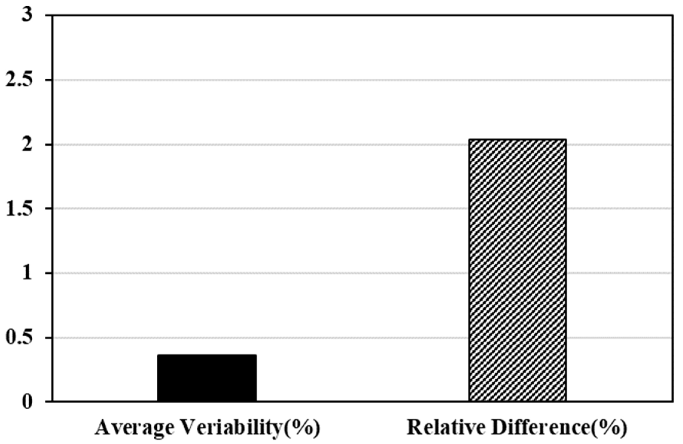
The variability due to equipment error and proficiency of the ultrasonic velocity measurement method was analyzed and found to be 0.36%. In the case of the ultrasonic velocity measurement method used in this study, the tester’s skill required in using the equipment was low, and a direct method was used in which the transmitter and receiver of the ultrasonic pulse passing through the core specimens were arranged in a straight line. Therefore, the results were lower than the general variability of other NDT instruments.
(2)
The relative difference between the results of ultrasonic velocity measurement of the half-cutting core specimens was evaluated at 2.04% to the effect of the thickness on the results of ultrasonic velocity measurement. As the half-cutting core specimens have gone through the process of cutting the surface, it is judged that the result is due to the micro structural difference between the surface conditions that came into contact with the probe before cutting and the surface conditions after cutting.
(3)
A soundness grade of ultrasonic velocity standard of concrete pavement was derived. The corresponding soundness criteria categorized ultrasonic velocity as 4400 m/s, 4100 m/s, 3500 m/s, and 3000 m/s, and the soundness of the concrete pavement was graded from “very good” to “very poor” with a grade of 5.
(4)
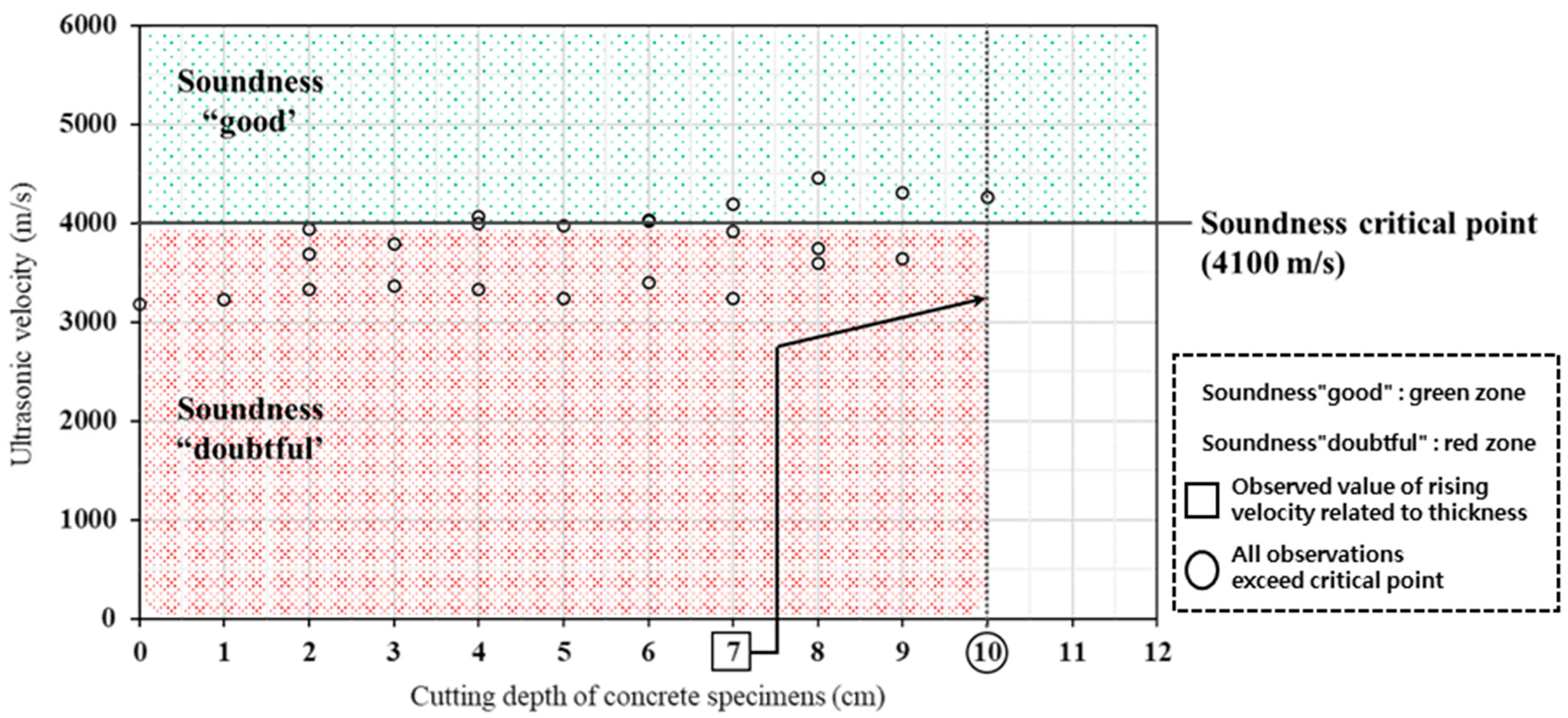
In order to estimate the depth of deterioration, a method of measuring the repetitive ultrasonic velocity of removing the deterioration areas was developed. As a result of analyzing the change in ultrasonic velocity depending on the depth of the deterioration removal of the core collected at the spalling damage point, it was confirmed that the tendency of the ultrasonic velocity increases according to the depth of the deterioration part removal.
(5)
According to the test method that was developed, the deterioration of the depth of the slab was analyzed to be from a minimum of 3 cm to 6 cm for spalls with widths < 150 mm, 7 cm to 10 cm for spalls with widths of 150 mm to 200 mm, and 9 cm to 13 cm for spalls with widths greater than 200 mm.
(6)
Referring to the results of this experiment, if the administration and road managers determine the depth of the degradation removal of the existing pavement for repair of the PCC pavement, three methods can be proposed according to the management level. The first method is cutting and repairing the existing pavement surface by more than 7 cm in the simplest way. The second is to determine the repair range in consideration of the predicted degradation depth according to the spalling severity presented above. The third is to directly measure the depth of degradation at the target point by means of repeated ultrasonic velocity testing of coring and degradation removal of the pavement in a way that can be used to determine the repair range based on quantitative test results at the target site.
(7)
This study conducted an ultrasonic velocity test by collecting cores from pavement under various conditions in South Korea to estimate the depth of deterioration of PCC pavement and develop a methodology to determine the repair range. As a further study to overcome the limitations of test results, it is necessary to develop a methodology for estimating degradation depth through an indirect ultrasonic velocity test available in the field and improve the soundness rating by reflecting the measurement range of ultrasonic velocity according to environmental variables.

Author Contributions

Conceptualization, I.K. and G.Y.; methodology, I.K. and G.Y.; investigation, J.C. and H.Y.; original draft preparation, G.Y.; writing—review and edition, S.H. and H.Y. All authors have read and agreed to the published version of the manuscript.

Funding

This study was conducted under research project ⎡Development of High-Performance Concrete Pavement Maintenance Technology to Extend Roadway Life (Project No.: 22POQW-B146691-05)⎦ funded by the Ministry of Land, Infrastructure and Transport (MOLIT) and the Korea Agency for Infrastructure Technology Advancement (KAIA). The authors would like to thank the members of the research team, MOLIT, and KAIA for their guidance and support throughout the project.

Institutional Review Board Statement

Not applicable.

Informed Consent Statement

Not applicable.

Data Availability Statement

Not applicable.

Conflicts of Interest

The authors declare no conflict of interest.

References

  1. Ministry of Land, Infrastructure; Korea Institute of Civil Engineering and Building Technology. Yearbook of Road Statistics. 2015. Available online: https://library.krihs.re.kr/search/detail/CATTOT000000205045 (accessed on 29 August 2022).
  2. Ministry of Land, Infrastructure, and Transport Statistics. Status on Road Repair and Maintenance. 2020. Available online: http://www.rsis.kr/maintenance_profit_summary.htm (accessed on 29 August 2022).
  3. Korea Expressway Corporation. An Application Study on Selecting Proper and Optimized Sections for Remodeling of Aged Pavement. KEC Report. 2017. Available online: https://www.codil.or.kr/viewDtlConRpt.do?gubun=rpt&pMetaCode=OTKCRK180287 (accessed on 29 August 2022).
  4. Kim, J.W.; Lee, J.H.; Park, C.W.; Jung, W.K. Applicability Evaluation of Measurement of Concrete Pavement Spalling Damage by Non-Destructive Test Methods. Int. J. Highw. Eng. 2019, 21, 1–10. [Google Scholar] [CrossRef]
  5. Lee, Y.H.; Kim, H.S.; Jung, W.K.; Oh, H.J.; Kim, H.B. Re-Repair Method for Deterioration of Partial Depth Repair Section in Portland Cement Concrete Pavement. Int. J. Highw. Eng. 2017, 19, 33–42. [Google Scholar] [CrossRef]
  6. Choi, M.K. A Study on the Selection of Partial Section Repair Range Using Impact Echo Method. Ph.D. Thesis, Inha University, Incheon, Korea, 2020. [Google Scholar]
  7. Park, J.W.; Kim, Y.K.; Han, S.H.; Lee, S.W. Performance Evaluation of Bonded Concrete Overlay in Highway. Int. J. Highw. Eng. 2014, 16, 1–10. [Google Scholar] [CrossRef]
  8. Korea Authority of Land & Infrastructure Safety. Development of Strength Estimation Formula for High-Strength Concrete. KISTEC Report. 2014. Available online: https://www.codil.or.kr/viewDtlConRpt.do?gubun=rpt&pMetaCode=OTKCRK180834 (accessed on 29 August 2022).
  9. Helal, J.; Sofi, M.; Mendis, P.A. Non-Destructive Testing of Concrete: A Review of Methods. Electron. J. Struct. Eng. 2015, 14, 97–105. [Google Scholar] [CrossRef]
  10. Whitehurst, E. Soniscope tests concrete structures. J. Am. Concr. Inst. 1951, 47, 443–444. [Google Scholar]
  11. Jones, R. Testing of Concrete by Ultrasonic-Pulse Technique. In Proceedings of the Thirty-Second Annual Meeting of the Highway Research Board, Washington, DC, USA, 13–16 January 1953; Volume 32, pp. 258–275. [Google Scholar]
  12. Raina, V.K. Concrete for Construction: Facts and Practice; Tata McGraw-Hill: New Delhi, India, 1988; pp. 68–113. [Google Scholar]
  13. IS13311; Part 1: Non-Destructive of Concrete Methods of Test. Bureau of Indian Standards: Delhi, India, 1992.
  14. BS1881-203; Recommendations for Measurement of Velocity of Ultrasonic Pulses in Concrete. British Standards Institution: London, UK, 1986.
  15. Song, H.W.; Velu, S. Corrosion Monitoring of Reinforced Concrete Structures. Int. J. Electrochem. Sci. 2007, 2, 1–28. [Google Scholar]
  16. Agustin, S.; Kerry, H.; John, S.P. Comparative Study of Rebound Hammer, Nitto Hammer, and Pullout Tests to Estimate Concrete In-Place Strength by Using Random Sampling Analysis. J. Transp. Res. Board 2017, 2629, 104–111. [Google Scholar]
  17. Federal Highway Administration Research and Technology. Available online: https://www.fhwa.dot.gov/publications/research/infrastructure/pavements/ltpp/reports/03031/02.cfm (accessed on 29 August 2022).
Figure 1. Core drilling position of concrete pavement slab around spalling.
Applsci 12 09881 g001
Figure 2. ACS A 1410 Pulsar equipment and direct method to evaluate concrete specimens using ultrasonic velocity.
Applsci 12 09881 g002
Figure 3. Concepts of NDT variability.
Applsci 12 09881 g003
Figure 4. Repeated ultrasonic velocity test method for deterioration area removal.
Applsci 12 09881 g004
Figure 5. Variability results of ultrasonic velocity investigation methods.
Applsci 12 09881 g005
Figure 6. Concept of the box plot in statistical analysis.
Applsci 12 09881 g006
Figure 7. Results for concrete soundness grade standard “good” using ultrasonic velocity.
Applsci 12 09881 g007
Figure 8. Ultrasonic velocity test for the cutting depth of core specimens.
Applsci 12 09881 g008
Figure 9. Ultrasonic velocity result according to the cutting thickness of the core specimens (Spalling severity with middle and lower section).
Applsci 12 09881 g009
Figure 10. Ultrasonic velocity result according to the cutting thickness of the core specimens (Spalling severity with width section).
Applsci 12 09881 g010
Figure 11. Ultrasonic velocity result according to the cutting thickness of the core specimens (Spalling severity with highest section).
Applsci 12 09881 g011
Figure 12. Estimation depth of concrete pavement deterioration.
Applsci 12 09881 g012
Table 1. Concrete pavement mixing ratio based on quality of expressway pavement materials in South Korea.
CategoryGmax
(mm)
Slump
(mm)
Air
(%)
W/B
(%)
S/a
(%)
Unit Weighting (kg/m3)Note
WBinderSG
CF.A
M125405–74541151336-7331091Before 2002
M225405–74538147326-69111492002–2009
M325405–743361502807063011502009–2018
M425405–73836.5154324816131087After 2018
Table 2. Information of core specimens of the concrete pavement slab.
LocationConcrete PerformanceSurface ConditionsNumber of Core Specimens
Test specimensLaboratory-No distresses8
Core drillingHighwayless than 5 yearsNo distresses23
National highway8 years to 20 yearsNo distresses16
National highwaymore than 20 yearsSpalling damage31
National highwaymore than 20 yearsNo distresses4
Table 3. Reference of typical concrete quality “good” using the ultrasonic velocity range.
Proposal and CriteriaLower Limit UPV
(m/s)
Upper Limit UPV
(m/s)
Whitehurst, E. (1951) [10]35004500
Jones, R. (1953) [11]41004700
Raina, V.K. (1988) [12]36554570
IS 13311-1992 [13]35004500
BS 1881-203:1986 [14]35004500
Song, H.W. (2007) [15]35004000
Table 4. Soundness rating based on ultrasonic velocity of concrete pavement.
Ultrasonic Velocity (m/s)Relative Difference on Ultrasonic Velocity (%)Soundness Grade on Concrete Pavement
More than 4400100Very good
4100 ≤ UV < 440093~100Good
3500 ≤ UV < 410080~93Doubtful
3000 ≤ UV < 350068~80Poor
Lower than 300068Very poor
Publisher’s Note: MDPI stays neutral with regard to jurisdictional claims in published maps and institutional affiliations.

