
Responses of Laterally Loaded Single Piles Subjected to Various Loading Rates in a Poroelastic Soil


Department of Civil Engineering, National Taipei University of Technology (Taipei Tech), Taipei 10608, Taiwan
*
Author to whom correspondence should be addressed.
Appl. Sci. 2022, 12(2), 617; https://0-doi-org.brum.beds.ac.uk/10.3390/app12020617
Submission received: 21 November 2021
/
Revised: 29 December 2021
/
Accepted: 7 January 2022
/
Published: 10 January 2022
(This article belongs to the Special Issue Recent Progress on Advanced Foundation Engineering)
Abstract
:Groundwater table has an important role in soil–structure interaction problems. However, analysis of laterally loaded single piles has often been conducted by solely considering the mechanics of the soil skeleton or decoupling the interactive mechanics of the soil skeleton and the fluid flux; in other words, most analyses were performed without taking into consideration the coupling effect between the soil skeleton and the fluid flux. To improve our understanding of the hydromechanical coupling effect on laterally loaded single piles, a series of finite element study on laterally loaded single piles in saturated porous media was conducted. The effect of pile cap geometries, cap widths, cap embedment depths, and pile lengths, on the response of laterally loaded single piles was also studied. The loading condition of the pile was found to have a significant effect on the generation of excess pore-water pressure. The lateral displacement and bending moment computed at the maximum excess pore water pressure, which in turn, is equivalent to an undrained analysis, produced the minimum responses among all the other loading conditions. The effect of pile cap geometries was found to be much less significant than anticipated.
1. Introduction
Pile foundation, among many underground structures, is an embedded structure in a soil mass and is used to transfer and resist loads through its body and tip. In practice, piles may be subjected to uniaxial and combined loading systems that are tied up with a single or group system to share or move loads through its body and tip to the surrounding soil when used in conjunction with the reinforced pile cap on top of the pile. A wide range of studies have been reported on the impact of various loadings on single and group piles. Experimental, elastic theory, curve, and finite element (FE) methods are some of the common methods used in tackling issues that are related to the problem of pile and pile cap subjected to various loading.
Small-scale and full-scale lateral load experiments on single piles and pile groups with pile caps of different elevations from the ground surface, of varying sizes and thicknesses, and of different pile spacings in a pile group have been studied by Nath and Hazarika [1], El-Garhy et al. [2], Mokwa and Duncan [3], etc. Nath and Hazarika [1] experimentally studied the lateral resistance of a pile cap subjected to different depths of cap embedment, pile group axial capacities, pile spacings, and material properties. El-Garhy et al. [2] experimentally studied the effect of pile cap elevation below the ground surface and pile spacing on lateral resistance of a single pile and pile groups driven in sand and concluded that the lateral carrying capacity of single pile and pile groups increases as the pile cap embedment depth below the ground surface increases, and as the spacing between piles in the group increases. Soil hardness and strength adjacent to the pile cap have been found to affect the pile cap’s lateral resistance and overall contribution. Consistent results show that increasing pile cap elevation, pile cap size, and pile cap thickness have been found to have significant impact on lateral resistance and pile cap deflection.
Hansen and Christensen [4] and Broms [5] were perhaps the first few to use simple analytical formulae to calculate the deflection, rotation, moment, and bearing capacity of laterally loaded piles. Wu et al. [6] used basic analytical formulae to evaluate the responses of laterally loaded piles. Liao and Lin [7] proposed an analytical model based on energy conservation of the pile–soil system to evaluate the deflection of laterally loaded piles. Zhang et al. [8] assessed the static behavior of vertical piles using a nonlinear analysis based on the subgrade reaction model with elastic, perfectly plastic soils for laterally loaded piles embedded in multiple-layered soil systems. Their study indicated that the behavior of a laterally loaded pile is controlled by the stiffness of the soil at shallow depth. Assuming the soil skeleton deforms elastically and under plane strain condition, Osman and Randolph [9] obtained a closed-form analytical solution for the consolidation of soil around a laterally loaded pile. They idealized their problem as a circular rigid disk surrounded by a deformable soil zone and assumed the drainage to occur at the boundary of the assumed zone of deformable soil around the pile. The excess pore water pressure response around the pile was then obtained using an uncoupled consolidation analysis. Although the study considered the generation of excess pore-water pressure for laterally loaded piles, the result is limited to the elastic soil; however, when comparing to the result of three-dimensional (3D) analysis, the two-dimensional (2D) analysis can still reasonably predict the consolidation process along the shaft of the pile.
Budhu and Davies [10] studied the response of laterally loaded single piles embedded in cohesionless soils using the boundary element method and taking into consideration soil yielding along the pile–soil interface and linearly increasing soil stiffness with depth. Their results show that soil yielding significantly increases the pile bending moments and lateral displacements. Finite difference analysis using FLAC3D has also been performed on a single pile subjected to lateral load [11]; different pile cap sizes and pile lengths have been considered. The findings were that the influence of the pile cap on the soil is mainly within the first quarter of the pile length, and that the pile cap would affect the location of the maximum soil resistance, and if the critical load is reached, the maximum soil resistance would increase with the sizes of the cap. Gupta and Basu [12] developed a continuum-based nonlinear analysis of laterally loaded piles. The nonlinear behavior of sands and clays were represented by the nonlinear elastic constitutive model, in particular, the hyperbolic modulus-reduction model. It was concluded that the lateral load of pile head settlement can be overestimated by 60–80% if linear elastic analysis is performed with small-strain elastic modulus instead of their nonlinear analysis.
Budiman and Ahn [13] conducted numerical analyses of single pile and pile group in clayey soils subjected to monotonous lateral loading using the FE program ABAQUS on free head and embedded capped piles. Their results show that pile cap size influences the lateral capacity of single pile, while the pile–soil–pile interaction and the cap embedment depth affects the resistance in the leading pile of the pile group. Ding et al. [14] numerically examined the effect of the pile cap on lateral capacity of a single pile with and without a pile cap in clayey soil, also using the FE program ABAQUS. They investigated the influence of cap area, embedded depth and vertical load on the pile’s lateral capacity and found that the lateral resistance of the pile is influenced by the embedment depth and the thickness of the pile cap; the larger the cap’s surface area, the greater the pile cap’s lateral resistance. The vertical load in the case of pile without cap has little influence on the capacity but in the case of pile with cap, the vertical load could significantly raise the lateral capacity of the pile. Nath and Hazarika [15] numerically analyzed the interaction of pile–soil–cap under lateral load, taking into account the effects of pile spacings and pile diameters. The analysis was conducted using Plaxis 2D and under drained condition with Mohr–Coulomb failure criteria. The conclusion was that the greater the depth of the pile cap from the ground surface, the greater the cap’s lateral resistance. To study the influence of excess pore-water pressure build-up on the response of laterally loaded single micropiles, Shahrour and Ata [16] performed a three-dimensional finite element simulation with Biot’s theory for the fluid–soil skeleton coupling. Their soil was represented by an elastoplastic constitutive relation with a non-associated Mohr–Coulomb flow rule. It was found that the excess pore fluid pressure is mainly induced in the proximity of the pile head, and it dissipated quickly.
Geotechnical engineering problems require a thorough understanding of the relationship between the porous soil and the interaction between the various multiphysics. The characteristic of a porous soil, in which a pile is buried, is that it generates excess pore-water pressure, which reduces the effective stress of the porous soil and, hence, its shear strength, which could lead to disastrous consequences. The term used to describe the interaction between the fluid flow and solids deformation within a porous medium is called “poroelasticity”.
Most of the soil–pile interaction simulations presented above involved only the solid mechanic part of the problem; simulation based upon the poroelastic constitutive framework has rarely been encountered, probably, because simulation based on solid mechanics without accounting for the fluid flux generated through the pores space of the soil often leads to a quick result. Some of the studies arrived at different conclusions for various reasons and variables, probably because they did not take into account the influence of the interaction between the poroelastic media and the fluid flux due to the presence of the groundwater. To improve our understanding in the effect of coupling the displacement-pore-water pressure on the response of laterally loaded piles, a series of numerical analyses were performed in this study. The generation and dissipation of the excess pore-water pressure and the responses of the pile during various loading conditions were then compared and discussed.
2. Method and Materials
A quasistatic numerical analysis of laterally loaded single piles under three different loading conditions, undrained, partially drained, and drained, and with various pile cap widths, pile cap embedment depths, and pile lengths in a poroelastic-plastic saturated soil, was performed. As the loading process involves the flow of water and the subsequent change in the effective stresses of the surrounding soil, a staged poroelastic soil model with Darcy’s flow coupling was simulated to assess the evolution of excess pore-water pressure in the vicinity of the pile body during the loading process. For ease of analysis, a two-dimensional plain strain analysis was used in the analysis. The pile was assumed to be an end-bearing pile and under an incremental lateral load, thus the pile friction is not a concern in this study.
2.1. Governing Equations and Boundary Conditions
When an external load is applied to a porous medium, the volume fraction of the pores is affected. The fluid-filled pores experience a change in pressure under this mechanical stress and, in turn, it leads to fluid motion. As a reaction to the change in pore volume, the solid material repositions and deforms elastically. In short, the loading process involves at least two phenomena—fluid motion (hydraulic behavior) and a change in the material’s effective stress (mechanical behavior). As these phenomena occur at the same time, they must be analyzed simultaneously; thus, a coupled hydromechanical analysis is required. In the case of, in particular, a sudden force applied to a poroelastic body, the displacement and fluid pressure with each representative elementary volume would adjust itself instantaneously to maintain a state of internal equilibrium [17]. Thus, the full combined formulation of soil–structure and fluid metaphysics may be represented by Biot’s system of equations:
where G is the shear modulus, is the displacement corresponding to the direction, respectively, is the body force in the respected direction, is the Biot–Willis coefficient, and p is the fluid or pore pressure.
From the quasistatic linear poroelastic theory, the fluid flow through a deformable porous medium expresses the solid mechanics equilibrium and fluid mass conservation as functions of both the solid phase displacement field and pore fluid pressure as [17,18,19]
where is the viscosity of the fluid, ∇ is the gradient operator, k is the intrinsic permeability, is the fluid density, g is the acceleration of gravity, z is the elevation potential, is the volumetric strain of the porous medium, and M is the Biot’s modulus, which is given by
where is the solid bulk modulus, is the fluid bulk modulus, and n is the porosity of the porous material. For an uncoupled analysis, the Biot–Willis coefficient is set to zero. To evaluate the deformation of the porous soil as a result of fluid motion, the solution of the above Biot’s system of Equation (1) and the fluid mass flow Equation (2) were simultaneously computed using a commercial partial differential equations (PDE) solver COMSOL [20] through its built-in poroelasticity interface.
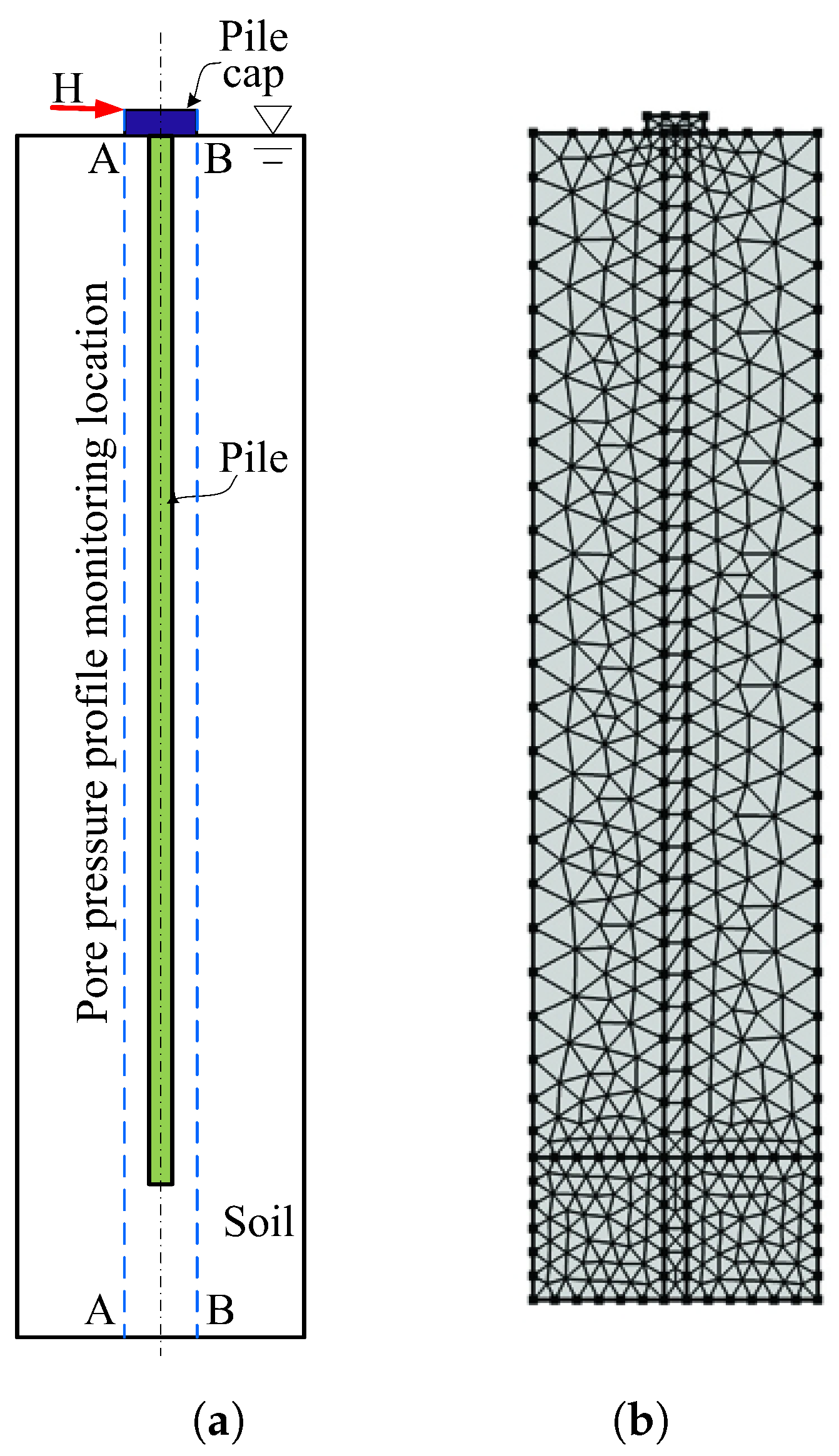
The pile–soil interaction of a capped pile in a completely saturated soil is studied here using an integrated multiphysics model. The study pile was 0.4 m wide by 18.0 m long and the pile cap was 1.0 m × 1.0 m × 0.3 m thick. A schematic layout of the study problem is shown in Figure 1a. To solve the solid mechanics governing equations, sufficient boundary conditions must be provided: the left and right boundaries of the model were constrained by roller support, the bottom boundary was constrained by fixed pinned, while the top boundary was left free. A pressure head of 20.5 m was assigned at the bottom boundary, representing a full height of ground water table, while the top boundary was set free for the Darcy’s water governing equation. The model is discretized into small triangular mesh, as shown in Figure 1b. As the simulation was executed in a coupled model consisting of the solid mechanics of the porous soil–structure interaction and the fluid motion, the mesh was generated for the above combined physics to produce a better-quality result. In the soil–structure interaction problem, Lagrange elements have been found to perform better than the serendipity elements. However, due to the extra internal nodes, for problems involving plastic yielding of soil, the Lagrange elements require the formulation of a larger matrix and, hence, more computational time and cost than that of the serendipity elements. Although the triangular serendipity element has fewer nodes per element, it often exhibits good accuracy for the same mesh compared to the Lagrange elements [20]. To tackle the bending problem of the pile structure, instead of the higher order elements, we use the quadratic triangular serendipity element with extra fine elements in the vicinity of the pile–soil boundary for smooth translation of degree of freedoms while fine mesh was provided for the zone away from the pile–soil boundary. The mesh consists of a total of 753 triangular elements with an average mesh quality, which was based on the skewness parameter, of 0.8. In general, only elements with a quality of less than 0.1 are considered as poor quality [20].
2.2. Material Properties
The hydromechanical poroelasticity coupling between fluid flow and structural deformation has been formulated using Biot’s constitutive and governing equations. The nonlinear material plasticity of the soil during the application of the lateral load on the pile cap is characterized by the Drucker–Prager’s yield criterion with nonassociated flow rule. The elastic characteristic of the concrete pile and pile cap is represented by the linear elastic model. The input parameters for the soil used in the analysis are tabulated in Table 1.
For a seamless transition of degree of freedom from the pile to the soil, the interface between the pile body and the surrounding soil is represented via a spring interface. The interface decouples the displacements between two sides of the boundary. The two boundaries are then connected by elastic and viscous forces with equal size but opposite directions, proportional to the relative displacements and velocities [20]; when the stiffness is given in terms of actual material data and layer thickness , the stiffness in the normal direction is computed based on a state of plane strain, so that
where E and are the modulus of elasticity and Poisson’s ratio of the soil, respectively.
3. Results
The influence of various parameters on the response of the pile during the application of the incremental lateral loading on the pile cap was numerically studied. The geometrical effect of the pile and pile cap, in particular, the pile cap size, pile cap elevation, and pile length on the response of the pile, were parametrically evaluated. In addition, the pile–soil interaction of completely saturated soil without a pile cap was also studied, using this integrated multiphysics model. As mentioned in the previous section, in the following coupled analysis, a lateral load of 200 kN was incrementally applied to the pile cap under various loading conditions: fast loading rate (2 kN/s), i.e., undrained condition, slow loading rate (2 kN/h), i.e., partially drained condition, and almost stationary loading rate (2 kN/day), i.e., drained condition. A further analysis considering dry soil was also performed. The results of the analysis are interpreted in terms of the excess pore-water pressure generated in the porous medium and the mechanical response of the pile. The excess pore-water was imposed by the elastic property of the porous media, which is due to the initial geostatic stress distribution of the porous media and the interaction between the porous media and the laterally loaded pile.
3.1. Pore-Water Pressure Distribution
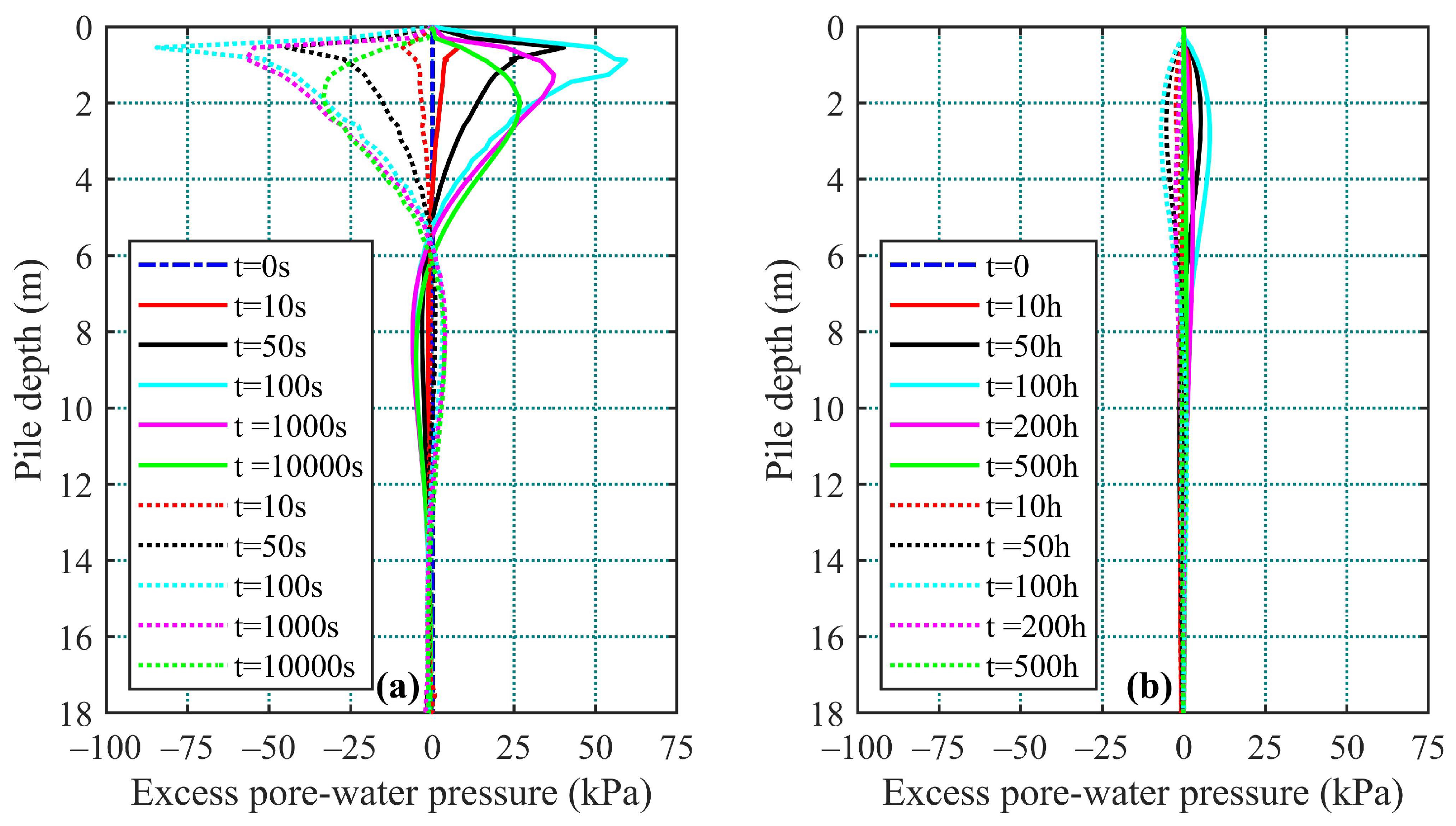
To see the effect of loading rates on the pore-water pressure of the porous media, the pile was laterally loaded under a fast transient loading rate of 2 kN/s, a slow transient loading rate of 2 kN/h, and an almost stationary loading rate of 2 kN/day over a total period of 100 s, 100 h, and 100 days, respectively. In all cases, the final lateral load acting on the pile cap at the end of the incremental loading stage was thus the same at 200 kN. The analyses were allowed to continue under this constant load and were only terminated at the end of 10,000 s, 500 h, and 500 days, respectively, to allow for the study of the response of the pile during the dissipation of the pore-water pressure. It was expected that during the loading process, in particular during the transient stage, excess pore-water pressure would be generated, and hence they were monitored at both the passive and active sides of the pile, i.e., 0.3 m from the left- and right-hand perimeters of the pile (Sec. A-A and Sec. B-B in Figure 1a). The observed excess pore-water pressure, which is the difference between the total pore-water pressure generated and the hydrostatic pressure, are plotted in Figure 2. In all cases, positive excess pore-water pressures were mainly observed in the passive zone (right-hand side, RHS) of the pile while negative excess pore-water pressures (suction) were mainly observed in the active zone (left-hand side, LHS) of the pile.
In the fast and slow transient loading cases, the maximum positive and negative excess pore-water pressures were both observed at the end of the loading, at t = 100 s (Figure 2a) and at t = 100 h (Figure 2b), respectively. The maximum positive excess pore-water pressure computed at t = 100 s was 53.4 kPa, and then it decreased to 37.3 kPa and 26.8 kPa at t = 1000 s and 10,000 s, respectively. The suction at t = 100 s was (−)84.5 kPa, the suction decreased to (−)57.0 and (−)33.3 kPa at t = 1000 s and 10,000 s, respectively.
Comparing the positive and negative excess pore-water pressure profiles under the slow loading rate (Figure 2b) to those under the fast loading rate (Figure 2a), the excess pore-water pressure profiles were rather symmetrical. The active side in the case of fast loading rate resulted in the generation of a higher excess pore-water pressure than the passive side, but as the loading rate decreased to the slow loading rate, the magnitude at both sides of the pile was almost equivalent. The absolute maximum excess pore-water pressure at the end of the incremental loading application at t = 100 h was about kPa (Figure 2b). One hundred hours after the end of this load application, the excess pore-water pressure dissipated some 90% of its maximum value generated at t = 100 h. In other words, the excess pore-water pressure gradually increased over a transitory period of 100 h, peaked at 100 h, and then dropped back to the hydrostatic pressure through the subsequent 100 h of consolidation. It was also observed that under the loading rate of 2 kN/h (Figure 2b), the excess pore-water pressure profiles were smoother than those under the loading rate of 2 kN/s.
For the case of almost-stationary loading rate, there was no discernible excess pore-water pressure generated throughout the loading stage. At this loading rate, full drainage was provided and, hence, its excess pore-water pressure remained at zero. Thus, it can be deduced that the current loading rate of 2 kN/s represents an undrained loading, the case of 2 kN/h represents a partially drained loading, and that of the 2 kN/day case represents a drained loading.
It was also observed in the current analysis that most of the production of the excess pore-water pressure was seen to occur in the top 6 m of the pile. The depth at which the maximum excess pore-water pressure was encountered was about 1.0 m immediately below the ground surface in the case of undrained loading, while that in the partially drained case the depth was about 2.5 m.
3.2. Pile Response during and after the Application of Lateral Load
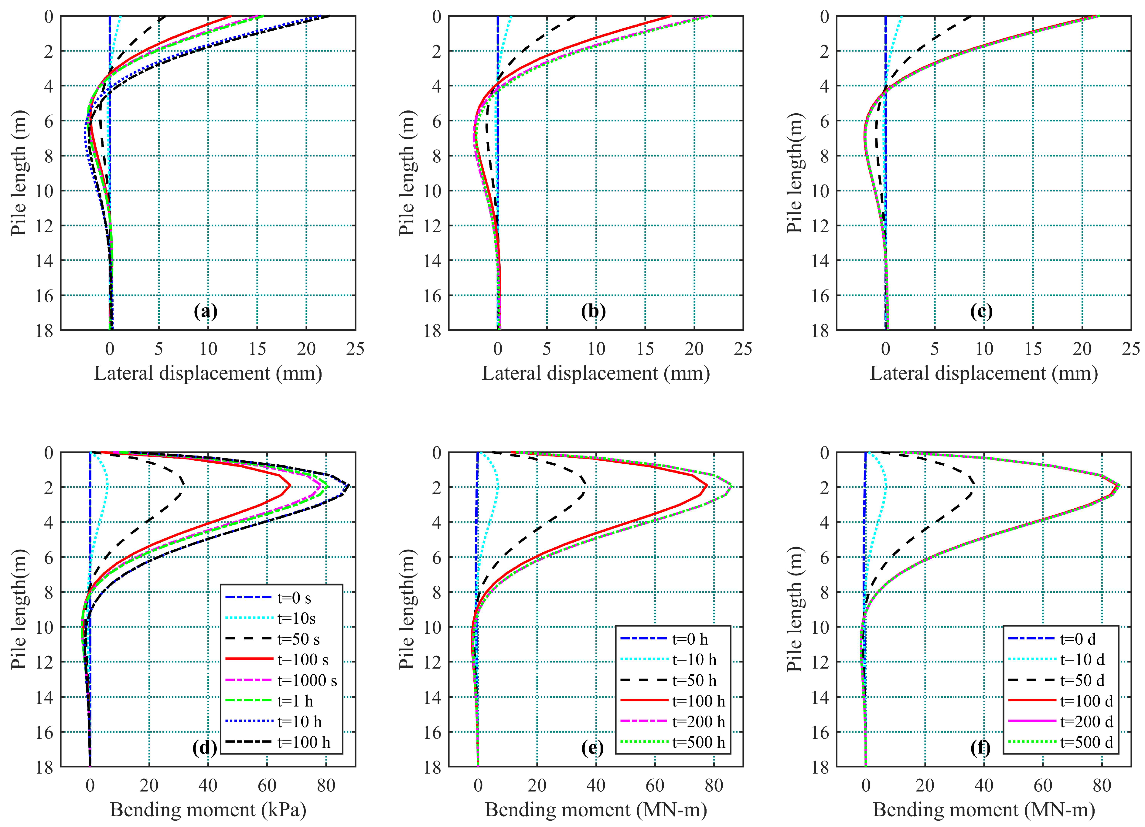
The response of the pile during and after the application of the incremental lateral load in undrained (loading rate at 2 kN/s), partially drained (loading rate at 2 kN/h), and drained (2 kN/day) conditions is studied here. At the end of the incremental loading, i.e., after t = 100 s, t = 100 h, and t = 100 days, the cumulative load attained was all the same, i.e., 200 kN; at which point, the displacements were 12.40 mm, 17.70 mm, and 21.37 mm, respectively (Table 2). The displacement results in Figure 3a–c and Table 2 revealed that the lateral displacement of the pile is affected by the consolidation process, i.e., the dissipation of the excess pore-water pressure. In Figure 3a, the lateral displacement of the pile cap was about 12.40 mm at t = 100 s; as the excess pore-water pressure continued to dissipate, the lateral displacement increased to about 21.46 mm at t = 10 h; subsequent consolidation, even for a further period of 100 h, saw only a minute (0.96 mm) or basically insignificant increase in the pile cap displacement.
In the case of partially drained loading, the maximum lateral displacement at the end of the incremental loading at t = 100 h was 17.70 mm; after letting it consolidate for 100 h (t = 200 h), at which time the excess pore-water pressure was about 34.5% of its maximum value at t = 100 h, it can be seen that almost all the lateral displacement was mobilized to a value of 21.43 mm (97.8% of the value at 1000 h). The effect of consolidation or dissipation of excess pore-water pressure on the lateral displacement of the pile is clearly demonstrated in the case of drained loading (Figure 3c) where the lateral displacement of the pile cap is identical at the end of 100, 200, and 500 days.
The distribution of bending moment , on the other hand, may be obtained from [21], as
where is the bending stiffness of the pile section, is the increment of the pile strain between two depths, and D is the diameter of the pile. The value of the pile bending moment rises throughout the loading stages to about 2.0 m of the pile depth (Figure 3d–f), then decreases to zero at depth of about 10 m. The maximum bending moment in the undrained, partially-drained, and drained cases is 87.67 MNm (at t = 100 h), 86.28 MNm (at t = 1000 h), and 85.87 MNm (at t = 500 days). The slight variation was because the consolidation process in the undrained and partially-drained cases had yet to reach 100%, albeit very close to it. It can be deduced from Figure 3d–f that the rate of bending moment increment at the end of the incremental loading, at t = 100 s and t = 100 h, reduces along with the dissipation of the excess pore-water pressure.
4. Parametric Study on Pile Cap Geometry
The pile cap is part of an important element of pile foundations, in particular, for laterally loaded piles. Studies on the contribution of the pile cap to the integrity of soil/pile interaction without considering the transient fluid flow conditions have been undertaken by various researchers. The effect of pile cap geometry, pile cap width, pile cap embedment depth, and pile length, on the response of laterally loaded single piles is evaluated here. The length of the pile used was 18.0 m, while the fully embedded pile cap was 1.0 m wide by 0.3 m thick. As in the previous section, three types of loading condition were considered: (i) undrained (loading rate = 2 kN/s), (ii) partially drained (loading rate = 2 kN/h), and (iii) drained (2 kN/d); for comparison purposes, a further loading condition, i.e., (iv) drained loading in dry soil (2 kN/step) was also conducted. All the analyses were terminated at the end of the incremental loading, i.e., when the total load of 200 kN was first attained, thus the effect of consolidation on the responses of the laterally loaded single piles is not taken into consideration. The results were evaluated in terms of lateral displacement and the lateral loading of the pile.
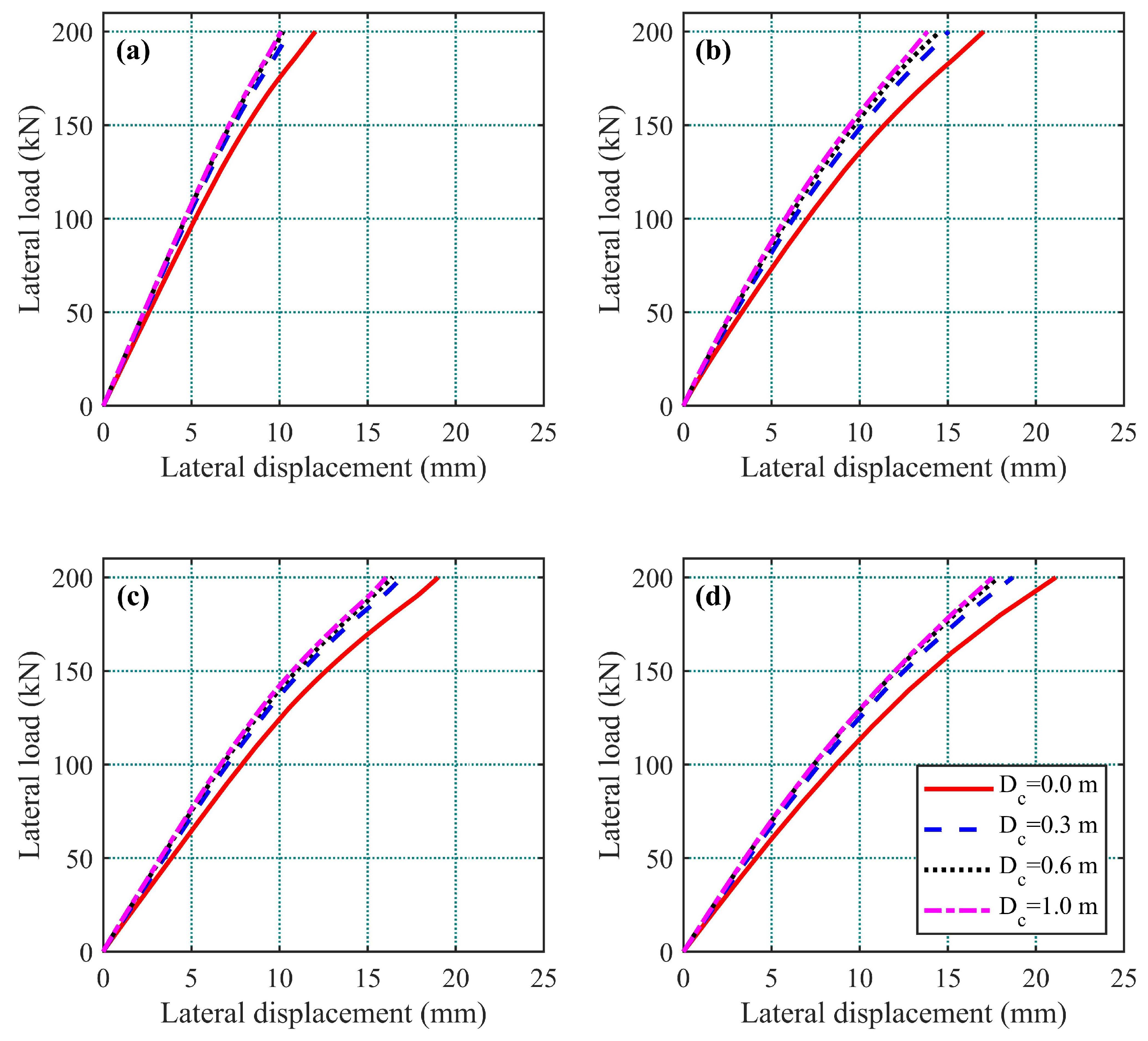
4.1. Effect of Pile Cap Embedment Depths
The pile cap embedment depths were parameterized for 0.0 m (no embedment), 0.3 m, 0.6 m, and 1.0 m in the ground with a lateral load applied at the top of the pile cap. The cap thickness was held constant at 0.3 m in this parametric study. Three cases of loading conditions were considered: undrained (loading rate = 2 kN/s), partially drained (loading rate = 2 kN/h), and drained (loading rate = 2 kN/d). An uncoupled analysis, represented by a dry soil with a step-loading of 2 kN/step is also included for comparison purposes. The corresponding results, plotted in terms of lateral load versus pile cap lateral displacement, immediately after the completion of the incremental load, are presented in Figure 4 and Table 3.
In all circumstances, the increment of the embedment depths of the pile cap is seen to have minor influences on the lateral displacement of the pile cap, where the displacement of the pile cap decreases as the depth of embedment of the pile cap increases. The effect of cap embedment depth begins to vanish when the embedment depth is deeper than 0.3 m. This is because most the resistance was indeed provided by the pile itself. In addition, it was observed that the pile cap displacement increases for all the cap embedment depths as the loading rate decreases from fast (2 kN/s) to almost stationary (2 kN/day). In all circumstances, the displacement of the pile cap at the end of the incremental lateral loading is smaller than the pile cap displacement in the case of the dry soil. This result is consistent with the findings of [15].
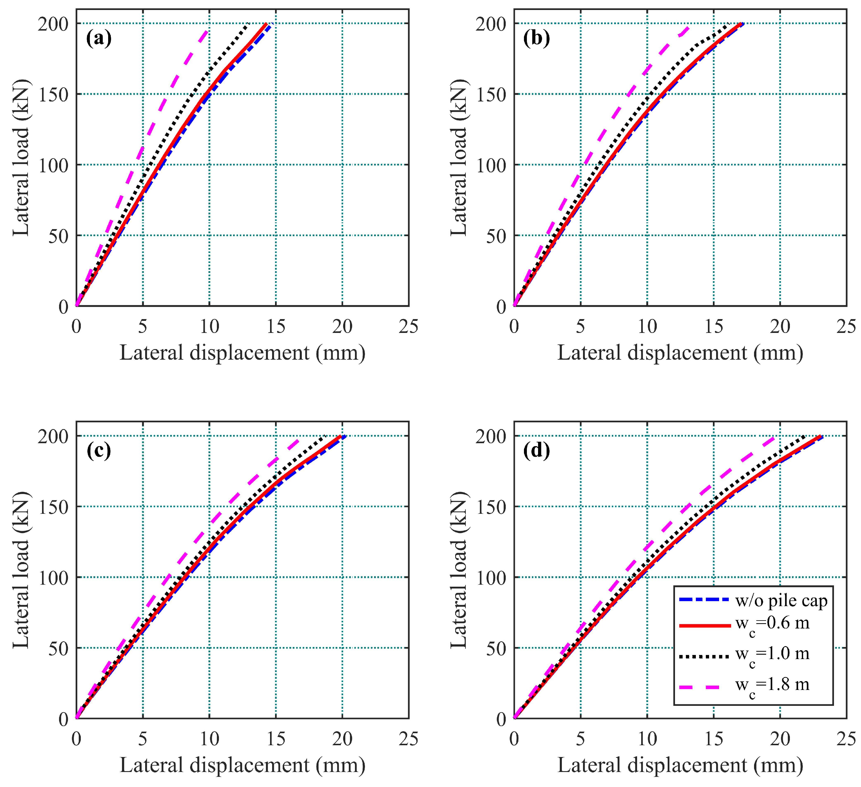
4.2. Effect of Pile Cap Widths
The width of the pile cap is also believed to have an impact on the response of the laterally loaded single piles. The lateral load versus lateral displacement relationship was examined for cap widths of 0.6 m, 1.0 m, and 1.8 m, as well as without the pile cap, as shown in Figure 5. The final displacement of the pile cap under various loading conditions is tabulated in Table 4. For all the loading conditions, i.e., the coupled and uncoupled dry soil analyses, the pile cap’s resistance rises, which was revealed by the reduction of the pile cap’s lateral displacement, as the pile cap width increases. For the cases of without pile cap and cap width of 0.6 m, their lateral displacements at the end of the incremental lateral loading were almost similar. A further increase in the cap width began to show a reduction in the lateral displacement of the pile cap; a discernible reduction is clearly seen when the cap width is increased to 1.8 m, in particular, in the case of the undrained loading (Figure 5a).
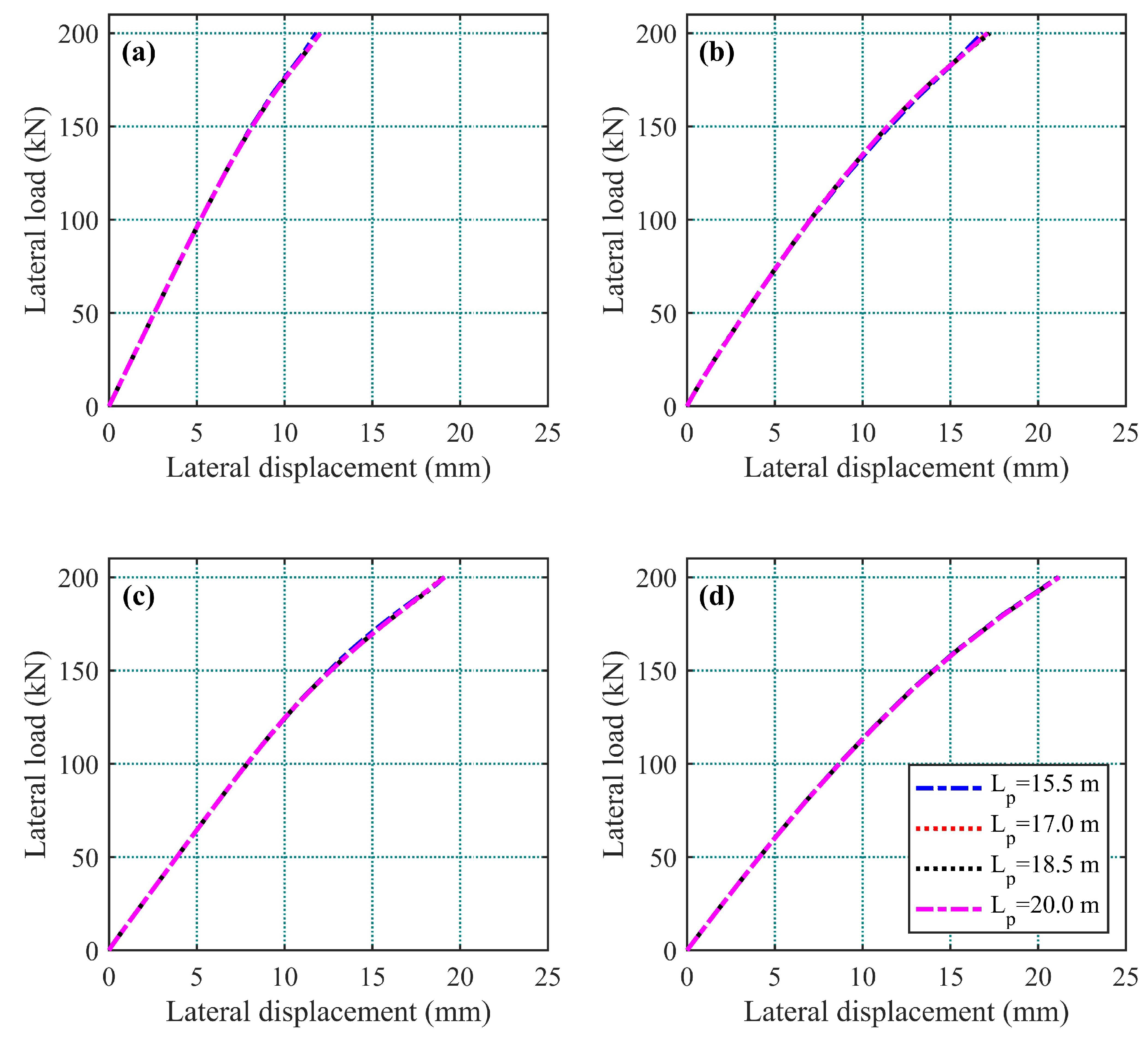
4.3. Effect of Pile Lengths
The effect of pile lengths on the pile response of the laterally loaded single piles was also examined in this study; various pile lengths of 15.5 m, 17.0 m, 18.5 m, and 20.0 m were considered. The ultimate lateral displacement of the laterally loaded single piles for undrained loading, partially drained loading, drained loading, and dry soil is, respectively, 12.0 mm, 17.1 mm, 19.0 mm, and 21.7 mm (Figure 6). However, for each of the loading cases, the results in Figure 6 show that the pile length has no influence on the corresponding lateral load–lateral displacement result. The result is plausible because, as seen from Figure 3, all the lateral displacements diminish at depth equals or greater than 13 m, which is the fixity point of the pile. Thus, as long as the length of the pile is greater than this point, the lateral displacement profile should therefore be unaffected. It should be noted that these studies only monitored the displacement generated during the incremental loading stage; therefore, these displacements were not their ultimate displacement, as the excess pore-water pressure dissipated, in particular, for the cases of undrained and partially drained loadings. Further displacement associated with the dissipation of excess pore-water pressure is expected to take place during the consolidation stage.
5. Discussion and Conclusions
The groundwater table plays a critical role in soil–structure interaction problems; however, most of the studies on laterally loaded single piles were seldom performed using the coupled hydromechanical governing equations or considering the soil as a porous media. The influence of the interaction of the porous soil media and the fluid flux during the loading stages of single piles was studied here using a coupled hydromechanical model for porous media.
A series of analyses, conducted under different loading conditions: undrained (fast loading rate), partially-drained (slow loading rate), and drained (almost stationary loading rate) conditions, was performed in this study. The deflection of the laterally loaded single piles resulted in the tendency of the soil to expand and compress, and hence caused the generation of the excess negative and positive pore-water pressures on both sides of the laterally loaded pile. It was observed that the loading rates of the pile resulted in different degree of excess pore-water pressure generation and that the generation of the excess pore-water pressure has a significant effect on the response of the laterally loaded single piles. Under the fast or undrained loading condition, the negative excess pore-water pressure generated on the active side of the laterally loaded pile yielded a greater value than the positive excess pore-water pressure on the passive side. As the loading rate decreases, the negative pore-water pressure on the active side drops to values less than that in the passive side. It was also found in this study that most of the generation of the excess pore-water pressure occurred within the top 6.0 m of the pile, albeit excess pore-water pressure was also observed after this depth, but its effect on the pile responses was insignificant.
The variation of the excess pore-water pressure generated in the porous soil media has a direct effect on the bending moment and lateral displacement of the piles. Under the undrained loading condition, the values of the lateral displacement and bending moment generated at the end of the incremental loading (i.e., t = 100 s), which corresponded to the maximum excess pore-water pressure, were the minimum among all the values observed in the three loading conditions, while for the drained loading case, the lateral displacement and bending moment were the maximum among all the loading conditions. This result implies that the effect of consolidation or dissipation of excess pore-water pressure on the responses of the piles can not be ignored, in particular, for the long-term performance of laterally loaded single piles.
For each of the loading conditions studied and among the three geometries of the pile and pile cap (cap width, cap embedment depth, and pile length), the width of the pile cap seemed to have the most influence compared to the other two geometries. In this study, the pile length does not seem to have any effect at all on the responses of the laterally loaded single piles.
Author Contributions
Conceptualization, A.A.A. and M.-W.G.; numerical analysis, A.A.A.; writing (first draft preparation), A.A.A.; writing (review and editing), M.-W.G. All authors have read and agreed to the published version of the manuscript.
Funding
This research received no external funding.
Institutional Review Board Statement
Not applicable.
Informed Consent Statement
Not applicable.
Data Availability Statement
Not applicable.
Acknowledgments
The authors’ gratitude goes to the reviewers for their helpful comments and constructive suggestions in improving this paper. The second author is grateful to Taipei Tech for providing the International Graduate Student Scholarship for his study.
Conflicts of Interest
The authors declare they have no conflicts of interest.
References
- Nath, U.K.; Hazarika, P.J. Lateral resistance of pile cap—An experimental investigation. Int. J. Geotech. Eng. 2013, 7, 266–272. [Google Scholar] [CrossRef]
- El-Garhy, B.; El-Nemr, M.; Shalaby, I. Effect of pile cap elevation below ground surface on lateral resistance of pile groups-experimental study. Int. J. Geotech. Eng. 2009, 3, 21–28. [Google Scholar] [CrossRef]
- Mokwa, R.L.; Duncan, J.M. Experimental evaluation of lateral-load resistance of pile caps. J. Geotech. Geoenviron. Eng. 2001, 127, 185–192. [Google Scholar] [CrossRef]
- Hansen, J.B.; Christensen, N.H. The ultimate resistance of rigid piles against transversal forces: Model tests with transversally loaded rigid piles in sand. In Akademiet for de tekniske Videnskaber; Geoteknisk Institut Bulletin: Copenhagen, Denmark, 1961; pp. 5–9. [Google Scholar]
- Broms, B.B. Lateral resistance of piles in cohesionless soils. J. Soil Mech. Found. Div. 1964, 90, 123–156. [Google Scholar] [CrossRef]
- Wu, D.Q.; Broms, B.B.; Choa, V. Design of laterally loaded piles in cohesive soils using p − y curves. Soils Found. 1998, 38, 17–26. [Google Scholar] [CrossRef] [Green Version]
- Liao, J.C.; Lin, S.S. An analytical model for deflection of laterally loaded piles. J. Mar. Sci. Technol. 2003, 11, 149–154. [Google Scholar] [CrossRef]
- Zhang, L.; Zhao, M.H.; Zou, X.J. Elastic-plastic solutions for laterally loaded piles in layered soils. J. Eng. Mech. 2013, 139, 1653–1657. [Google Scholar] [CrossRef]
- Osman, A.S.; Randolph, M.F. Analytical solution for the consolidation around a laterally loaded pile. Int. J. Geomech. 2012, 12, 199–208. [Google Scholar] [CrossRef] [Green Version]
- Budhu, M.; Davies, T.G. Nonlinear analysis of laterallly loaded piles in cohesionless soils. Can. Geotech. J. 1987, 24, 289–296. [Google Scholar] [CrossRef]
- Yu, S.K.; Zhang, Z.; Zhao, H.H. The influence of pile cap to p − y curves under lateral loads. In Proceedings of the 4th Geo-China Int Conf: Behavior of Geomaterials and Foundations for Civil Infrastructure Applications, Jinan, China, 25–27 July 2016; pp. 136–143. [Google Scholar]
- Gupta, B.K.; Basu, D. Nonlinear solutions for laterally loaded piles. Can. Geotech. J. 2019, 57, 1566–1580. [Google Scholar] [CrossRef]
- Budiman, J.; Ahn, K.K. Effects of pile cap in single pile and lateral capacity of pile group. In Proceedings of the Geo-Frontiers Congress 2005: Advances in Deep Foundations, Austin, TX, USA, 24–26 January 2005. [Google Scholar]
- Ding, C.H.; Wang, G.C.; Wang, J.C. Numerical simulation analysis on effect of pile cap to lateral capacity of single pile. In Proceedings of the 2010 International Conference on E-Product E-Service and E-Entertainment, Henan, China, 7–9 November 2010. [Google Scholar]
- Nath, U.K.; Hazarika, P.J. Parametric study of pile cap lateral resistance: Finite element analysis. Int. J. Geotech. Eng. 2013, 7, 273–281. [Google Scholar] [CrossRef]
- Shahrour, I.; Ata, N. Analysis of the consolidation of laterally loaded micropiles. Ground Improv. 2002, 6, 39–46. [Google Scholar] [CrossRef]
- Biot, M.A. General theory of three-dimensional consolidation. J. Appl. Phys. 1941, 12, 155–164. [Google Scholar] [CrossRef]
- Rice, J.R.; Cleary, M.P. Some basic stress diffusion solutions for fluid-saturated elastic porous media with compressible constituents. Rev. Geophys. Space Phys. 1976, 14, 227–241. [Google Scholar] [CrossRef]
- Pampillόn, P.; Santillάn, D.; Mosquera, J.C.; Cueto-Felgueroso, L. Geomechanical constraints on hydro-seismicity: Tidal forcing and reservoir operation. Water 2020, 12, 2724. [Google Scholar]
- COMSOL Multiphysics User Guide; Version 5.4; COMSOL AB: Stockholm, Sweden, 2018; Available online: www.comsol.com (accessed on 12 August 2021).
- Khati, B.S.; Sawant, V.A. Experimental study of laterally loaded pile group in square arrangement near sloping ground. Int. J. Geomech. 2021, 21, 040202. [Google Scholar] [CrossRef]
Figure 1.
(a) Schematic layout of the study problem; (b) typical numerical mesh used in the analysis.
Figure 1.
(a) Schematic layout of the study problem; (b) typical numerical mesh used in the analysis.

Figure 2.
Generation and dissipation of excess pore water pressure at Sec. A-A and Sec. B-B (see Figure 1a) during the loading of the pile: (a) fast loading rate: 2 kN/s (undrained); and (b) slow loading rate: 2 kN/h (partially drained).
Figure 2.
Generation and dissipation of excess pore water pressure at Sec. A-A and Sec. B-B (see Figure 1a) during the loading of the pile: (a) fast loading rate: 2 kN/s (undrained); and (b) slow loading rate: 2 kN/h (partially drained).

Figure 3.
Responses of pile under various loading rates: lateral displacement under the rate of (a) 2 kN/s (undrained); (b) 2 kN/h (partially drained); (c) 2 kN/day (drained); bending moment under the rate of (d) 2 kN/s (undrained); (e) 2 kN/h (partially drained); and (f) 2 kN/day (drained).
Figure 3.
Responses of pile under various loading rates: lateral displacement under the rate of (a) 2 kN/s (undrained); (b) 2 kN/h (partially drained); (c) 2 kN/day (drained); bending moment under the rate of (d) 2 kN/s (undrained); (e) 2 kN/h (partially drained); and (f) 2 kN/day (drained).

Figure 4.
Effect of cap embedment depth on lateral displacement of pile cap: (a) undrained (loading rate = 2 kN/s); (b) partially drained (loading rate = 2 kN/h); (c) drained (loading rate = 2 kN/day); and (d) dry soil (loading rate = 2 kN/step).
Figure 4.
Effect of cap embedment depth on lateral displacement of pile cap: (a) undrained (loading rate = 2 kN/s); (b) partially drained (loading rate = 2 kN/h); (c) drained (loading rate = 2 kN/day); and (d) dry soil (loading rate = 2 kN/step).

Figure 5.
Effect of pile cap width on lateral displacement of pile cap: (a) undrained (loading rate = 2 kN/s); (b) partially drained (loading rate = 2 kN/h); (c) drained (loading rate = 2 kN/day); and (d) dry soil (loading rate = 2 kN/step).
Figure 5.
Effect of pile cap width on lateral displacement of pile cap: (a) undrained (loading rate = 2 kN/s); (b) partially drained (loading rate = 2 kN/h); (c) drained (loading rate = 2 kN/day); and (d) dry soil (loading rate = 2 kN/step).

Figure 6.
Effect of pile length on lateral displacement of pile cap: (a) undrained (loading rate = 2 kN/s); (b) partially drained (loading rate = 2 kN/h); (c) drained (loading rate = 2 kN/day); and (d) dry soil (loading rate = 2 kN/step).
Figure 6.
Effect of pile length on lateral displacement of pile cap: (a) undrained (loading rate = 2 kN/s); (b) partially drained (loading rate = 2 kN/h); (c) drained (loading rate = 2 kN/day); and (d) dry soil (loading rate = 2 kN/step).


Table 1.
Input parameters used in the analysis.
| Constants | Value |
|---|---|
| Elastic modulus of soil | 7.0 MPa |
| Poisson’s ratio of soil | 0.35 |
| Density of soil | 1690 kg/m |
| Void ratio | 0.6 |
| Apparent cohesion | 10.0 kPa |
| Angle of shearing | 13.3 |
| Saturated hydraulic conductivity | 3.22 m/s |
| Biot–Willis coefficient | 1.0 |
| Elastic modulus of concrete | 30.0 GPa |
| Poisson’s ratio of concrete | 0.156 |
| Density of concrete | 2500 kg/m |
Table 2.
Maximum pile responses under various loading rates and different elapsed times.
| Loading Rates | Pile Responses (Maximum) | Elapsed Time | |||||
|---|---|---|---|---|---|---|---|
| 2 kN/s (Undrained) | 10 s | 50 s | 100 s | 1 h | 10 h | 100 h | |
| Lateral displacement (mm) | 1.10 | 5.68 | 12.40 | 15.69 | 21.46 | 22.42 | |
| Bending moment (MNm) | 5.86 | 31.90 | 67.82 | 80.74 | 87.04 | 87.67 | |
| 2 kN/h (Partially-drained) | 10 h | 50 h | 100 h | 200 h | 500 h | 1000 h | |
| Lateral displacement (mm) | 1.37 | 7.89 | 17.70 | 21.43 | 21.84 | 21.90 | |
| Bending moment (MNm) | 6.71 | 36.73 | 77.59 | 86.13 | 86.23 | 86.28 | |
| 2 kN/day (Drained) | 10 days | 50 days | 100 days | 200 days | 500 days | — | |
| Lateral displacement (mm) | 1.64 | 8.73 | 21.37 | 21.77 | 21.77 | — | |
| Bending moment (MNm) | 6.77 | 36.83 | 85.22 | 85.87 | 85.87 | ||
Table 3.
Effect of pile cap embedment depth on lateral displacement of pile cap under various loading conditions and in dry soil.
Table 3.
Effect of pile cap embedment depth on lateral displacement of pile cap under various loading conditions and in dry soil.
| Cap | 2 kN/s | 2 kN/h | 2 kN/Day | 2 kN/Step |
|---|---|---|---|---|
| Embedment | (Undrained) | (Partially-Drained) | (Drained) | (Dry) |
| (m) | (m) | (m) | (m) | (m) |
| 0.0 | 12.0 | 17.0 | 19.0 | 21.1 |
| 0.3 | 10.6 | 15.0 | 16.9 | 18.7 |
| 0.6 | 10.2 | 14.6 | 16.4 | 17.9 |
| 1.0 | 10.1 | 13.8 | 16.0 | 17.5 |
Table 4.
Effect of cap width on displacement of pile cap under various loading conditions and in dry soil.
Table 4.
Effect of cap width on displacement of pile cap under various loading conditions and in dry soil.
| Cap | 2 kN/s | 2 kN/h | 2 kN/Day | 2 kN/Step |
|---|---|---|---|---|
| Width | (Undrained) | (Partially-Drained) | (Drained) | (Dry) |
| (m) | (m) | (m) | (m) | (m) |
| w/o cap | 14.8 | 17.2 | 20.2 | 23.3 |
| 0.6 | 14.3 | 17.1 | 19.9 | 23.1 |
| 1.0 | 13.0 | 16.1 | 18.7 | 21.9 |
| 1.8 | 10.2 | 13.4 | 17.1 | 19.8 |
Publisher’s Note: MDPI stays neutral with regard to jurisdictional claims in published maps and institutional affiliations. |
© 2022 by the authors. Licensee MDPI, Basel, Switzerland. This article is an open access article distributed under the terms and conditions of the Creative Commons Attribution (CC BY) license (https://creativecommons.org/licenses/by/4.0/).
Share and Cite
MDPI and ACS Style
Gui, M.-W.; Alebachew, A.A. Responses of Laterally Loaded Single Piles Subjected to Various Loading Rates in a Poroelastic Soil. Appl. Sci. 2022, 12, 617. https://0-doi-org.brum.beds.ac.uk/10.3390/app12020617
AMA Style
Gui M-W, Alebachew AA. Responses of Laterally Loaded Single Piles Subjected to Various Loading Rates in a Poroelastic Soil. Applied Sciences. 2022; 12(2):617. https://0-doi-org.brum.beds.ac.uk/10.3390/app12020617
Chicago/Turabian StyleGui, Meen-Wah, and Alex A. Alebachew. 2022. "Responses of Laterally Loaded Single Piles Subjected to Various Loading Rates in a Poroelastic Soil" Applied Sciences 12, no. 2: 617. https://0-doi-org.brum.beds.ac.uk/10.3390/app12020617
Note that from the first issue of 2016, this journal uses article numbers instead of page numbers. See further details here.