
Mechanical Strength Study of a Cranial Implant Using Computational Tools
by
 , , and
Pedro O. Santos
1, 
Gustavo P. Carmo
1 ,
,
Ricardo J. Alves de Sousa
1,* ,
,
Fábio A. O. Fernandes
1 and
and
Mariusz Ptak
2
1
Center for Mechanical Technology an Automation, Department of Mechanical Engineering, Campus de Santiago, University of Aveiro, 3810-183 Aveiro, Portugal
2
Faculty of Mechanical Engineering, Wroclaw University of Science and Technology, Lukasiewicza 7/9, 50-371 Wrocław, Poland
*
Author to whom correspondence should be addressed.
Appl. Sci. 2022, 12(2), 878; https://0-doi-org.brum.beds.ac.uk/10.3390/app12020878
Submission received: 16 November 2021
/
Revised: 6 January 2022
/
Accepted: 12 January 2022
/
Published: 15 January 2022
(This article belongs to the Special Issue Biomechanics Research on Biological Soft Tissues)
Abstract
:The human head is sometimes subjected to impact loads that lead to skull fracture or other injuries that require the removal of part of the skull, which is called craniectomy. Consequently, the removed portion is replaced using autologous bone or alloplastic material. The aim of this work is to develop a cranial implant to fulfil a defect created on the skull and then study its mechanical performance by integrating it on a human head finite element model. The material chosen for the implant was PEEK, a thermoplastic polymer that has been recently used in cranioplasty. A6 numerical model head coupled with an implant was subjected to analysis to evaluate two parameters: the number of fixation screws that enhance the performance and ensure the structural integrity of the implant, and the implant’s capacity to protect the brain compared to the integral skull. The main findings point to the fact that, among all tested configurations of screws, the model with eight screws presents better performance when considering the von Mises stress field and the displacement field on the interface between the implant and the skull. Additionally, under the specific analyzed conditions, it is observable that the model with the implant offers more efficient brain protection when compared with the model with the integral skull.
1. Introduction
Cranioplasty is a medical-surgical procedure that aims to fill skull defects provoked by a craniectomy or skull fracture, recovering the skull’s protective function and also bringing aesthetic satisfaction to patients. Craniectomy is a surgical procedure where a part of the skull is removed to reduce pressure on the brain resulting from swelling or bleeding. Then, the surgeon fills the gap in the head using autologous bone or alloplastic material.
The human skull is a vital part of the human body, mainly because it has the task of protecting the brain, an essential organ of the human body. It is possible to divide the skull into two parts: the braincase (neurocranium) and the facial skeleton (viscerocranium) [1]. Skullbone is composed of both cortical bone and trabecular bone. Cortical bone is treated as a compact bone that acts as the outer layer of the skeleton, surrounding the trabecular bone and providing a hard covering for the skeleton [2]. On the other hand, trabecular bone is a sponge-like tissue configured in a lattice consistency situated in the core of bones [2]. Additionally, the skull contains cranial sutures, which act as connectors of the skull bones and are composed mainly of collagen [3]. Since the brain is a susceptible organ and needs the protection of all parts that surrounds it against impact loads, a good indicator of the effectiveness of external components, such as a cranial implant, is their capacity to protect the brain against severe injuries. Traumatic brain injury (TBI) can be classified as a combination of two parameters: deformation processes due to brain motion and indentation processes on the skull (or implant) [4].
Nowadays, evolution in Computer-Aided Design (CAD) and Additive Manufacturing (AM) has led to an increase in patient-specific cranial implant production in cranioplasty, which offers multiple advantages including good definition on the implant contour, high precision of curvature, reduced risk of surgical complications, and improved aesthetic results [5]. Four prominent materials can be used in cranioplasty: allografts or autografts, metal, polymers, and ceramic [6]. Furthermore, three materials have emerged as the most applied ones: titanium, poly(methyl methacrylate) (PMMA), and poly-ether-ether ketone (PEEK). In fact, PEEK is being widely used these, days since its mechanical properties, mainly the elastic modulus, are identical to bone’s, which helps prevent the stress shielding effect [7]. Moreover, it has many advantages such as high thermal stability, toughness, and rigidity; the facility to process, self-lubrication, abrasion resistance, and compatibility with computed tomography (CT) and magnetic resonance imaging (MRI) [7,8]. For these reasons, besides cranial implants, many applications of PEEK related to prosthodontics have also been reported [9,10,11].
As a crucial step for the implant design, computer-aided design for this type of components can follow templates, such as an average skull or a left-right mirrored image (in the case of a one-sided defect) [6]. When incorporating tissue engineering during implant development, CAD techniques should be employed to obtain the scaffold structure during the design process [12,13,14,15]. Otherwise, when creating a PEEK implant with no porosity, there is the necessity to incorporate small holes to help dural tack-up sutures and muscle suspension [16].
The technologies used to fabricate cranial implants by additive manufacture depend on the material family. In the case of synthetic polymers, since working with PMMA is a challenging task, PEEK obtained via SLS has been exploited by every company in this area [6]. One advantage of PEEK is that the design of implants can be modified to create material properties similar to the adjacent skull, making PEEK cranial implants more suitable than titanium ones [6].
The surgeon frequently chooses the fixation methods in cranioplasty based on experience. There are many fixation devices, with the most employed ones being titanium mini-plates, titanium tangential screws, and titanium clamps. The chosen fixation method, as well as the number of fixation points, are variables that play a massive role in avoiding the displacement of the implant. Despite leading to higher strain in the interface between bone and implant, tangential screws offer a more rigid fixation and, since they are directed tangentially into the bone, this method is entirely impalpable [5]. Additionally, there is a lower probability of implant displacement occurring when this is the employed method, as shown in related studies [17].
Different strategies, software, and methodologies have been employed to validate the developed models of cranial implants. These are the most critical steps of the mechanical resistance study, and all the assumptions made have significant impacts on the approximation made by the finite element analysis (FEA). Huys et al. [5] used Abaqus to run an FE analysis on three different models with similar strategies adopted: a PEEK cranial implant fixed with tangential screws, and two ceramic-titanium (CeTi) cranial implants fixed with tangential and axial screws. The complete head model was not used. Instead, to reduce the computational cost, only the part of the skull surrounding the defect was taken into account. All material properties were considered to be linear elastic and the contact between the different parts was assumed to occur only at the screw holes, with complete fixation assumed. Two static loads were applied to the model: one being an impact load due to a fall off a bicycle, applied as a pressure perpendicular to a circular area, and the other one being an internal pressure. Results showed that PEEK offers insufficient brain protection due to its high flexibility and local peak stresses at the bone-screw interface.
Huang et al. [12] executed FE analysis using the software ANSYS to study the biomechanical behavior of titanium mesh cranial implants with different thicknesses, pore structures, and surface characteristics, with all material properties treated as linear elastic, isotropic, and homogeneous. The skull was fixed in the bottom, a static load of 50 N was placed in the center of the implant, and the stress of the screws was neglected. Finally, results of the analysis showed that the stress distribution and peak von Mises stress of the implants decreases at the thickness of 1 mm, and implants with a circular pore pattern result in a lower von Mises stress on the bone defect area when compared with triangular and square pore patterns.
To compare the mechanical impact response of PEEK and hydroxyapatite (HA), a study was conducted by García-González et al. [15] performing explicit analysis using the software Abaqus (Dassault Systèmes, Velizy-Villacoublay, France). A complex finite element head model (FEHM) was used containing scalp, skull, cerebral falx, CSF, and brain tissues, and constitutive models for different parts of the human head were employed based on a selection from the literature. In contrast, for PEEK, a constitutive model previously developed by the authors was adopted. In the numerical model, the contact was modeled with a penalty contact algorithm with a friction coefficient of 0.4. Since the model does not include screws, a parallel analysis was developed to capture the stress concentration introduced by the screws, which was posteriorly applied. A set of numerical simulations were carried out studying the mechanical response of the FEHM for an impact velocity varying from 1 m/s to 7 m/s, including three different scenarios: an FEHM including a PEEK implant, an FEHM including a HA implant, and an FEHM including no defect. The results were then analyzed in three categories: acceleration-time predictions, critical impact velocity predictions, and TBI prediction. Results proved that a PEEK implant could be a much better choice in a demanding mechanical lifestyle, even though HA has better bio-integration properties.
This work aims to study the implant strength and capacity to protect the brain, contextualizing it in a highly detailed numerical head model. Since most of the previous related studies involved implicit analysis and material models with linear elastic behavior, the introduction of damage on both skullbone and implant is a differentiating factor. Two case studies will be investigated: (i) a parametric study to find the number of screws that enhances the model; (ii) implant capacity to protect the brain compared with the integral skull. All the assumptions and decisions made were based on previous validations made by other authors.
2. Materials and Methods
2.1. PEEK Viscoplasticity
To define the material model, a work presented by Garcia-González et al. [18] was taken into account and is explained in this section. This material model offers a more complete and suitable solution to define the material, including damage, dynamic behavior, and interesting thermomechanical phenomena reported for PEEK. The material model in this work adopts the Johnson–Cook (JC) model. The approach is justified by the observed strain rate and temperature sensitivity of PEEK, which indicates a viscoplastic behavior. This model is frequently used in finite element codes, including explicit analysis in Abaqus, and the strength model can be described as
where A is the yield strength at a quasi-static strain rate, B and n represent the influence of the strain hardening, m is the temperature sensitivity, is the initial temperature, and is the melting temperature, while the first term is the strain hardening , the second one is the strain rate sensitivity and the third one is related to thermal softening Θ, where
The equation
allows us to obtain the temperature increment in adiabatic conditions, with being the temperature increment, the room temperature, β the Quinney–Taylor heat fraction coefficient, the material density, and the specific heat at constant pressure. In this work, the author assumed the Quinney–Taylor heat fraction coefficient β to be constant and equal to 0.9.
As reported by Garcia-González et al. [18], all these parameters were determined by analyzing the results of the various compressive tests at different strain rates and temperatures following methodologies reported for ductile metals and polymers [19]. Parameters A, B, and n were determined by tests at room temperature and parameter C was identified by Equation (4) with different strain rates and null plastic strain () at room temperature. Thus, the temperature sensitivity parameter m was determined by Equation (5) for a range of temperatures ranging from the initial temperature to the melting temperature.
Table 1 contains the constants used to define the material behavior, in other words, the JC parameters.
2.2. PEEK Fracture Model
As reported by Garcia-González et al. [18], the fracture model is essential to providing a robust and complete model. To do so, the fracture model proposed by Johnson and Cook [20] was employed. It includes strain hardening, strain rate, temperature, and stress triaxiality, the last being a crucial factor to define PEEK. For this model, which is already employed for ductile metal alloys and semicrystalline polymers, failure is assumed when a D parameter surpasses unity. The evolution of D can be described as
where is an increment of accumulated plastic strain over an integration cycle and is the critical failure strain level. Next, the plastic failure strain is dependent on a plastic strain rate , a dimensionless pressure deviatoric stress ratio and a non dimensional temperature Θ. Equation (7) shows these dependencies with being the failure constants.
The authors of [18] indicated a value of , while and were determined based on experimental data of tensile tests at strain rates equal to 0.001 s−1 at room temperature [19]. The constants and were determined based on experimental data of uniaxial tests at different strain rates and temperatures [21].
2.3. Skull Defect Creation and New Mesh
The base finite element head model used in this work is the YEAHM (YEt Another Head Model), initially developed by Fernandes et al. [22] and afterwards improved by Migueis et al. [23], Costa et al. [24], and Barbosa et al. [25]. The model comprises a skull, brain, CSF, bridging veins (BV), and superior sagittal sinus (SSS). In the original model, the bone that makes up the skull was homogeneous and did not feature the distinction between cortical bone, trabecular bone, or cranial sutures. These details were added by Barbosa et al. [25], including a damage model. The material of the brain was modeled as hyper-viscoelastic, the CSF was considered to be a hyperelastic material, the SSS and BV were modeled with an elastoplastic law, and, in the model proposed by Barbosa et al. [25], the trabecular bone was modeled as elastic-plastic material, and the cortical bone and cranial sutures as quasi-brittle material.
The head model previously mentioned was manipulated with the software Hypermesh (Altair Engineering, Michigan, MA, USA) in order to obtain the skull model after the craniectomy. The option was to create a large skull defect with approximately 50 cm2 at the parietal zone to reproduce a realistic situation. Then, nodes were selected and an approximated contour of the implant at the desired skull location was performed and used to create a spline surface, which acted as a start point to obtain the skull defect and the implant. Once this surface was completed, it was used to create the defect in the skull to place the implant. The skull elements intersecting this surface along the thickness were deleted and then, to smooth the skull defect contour, the border elements were projected to this surface. Then, the skull model was exported to Abaqus. Using the tool Verify mesh from the Abaqus toolbox, some poor elements with near-zero volume on the defect’s border were identified and eliminated so that the analysis could be performed.
Overall, the skull’s new mesh contained 22,3401 linear hexahedral elements of type C3D8R, of which 124,714 are from cortical bone, 86,703 from trabecular bone, and 11,984 from cranial sutures. Figure 1 depicts the modeling steps of the defective skull.
2.4. Implant Geometry and Mesh
The surface obtained after creating the hole in the skull was given a thickness of 4 mm, a decision made based on previous studies [26] where the influence of different thicknesses was evaluated using FEM under three loading scenarios. The implant thickness contained a chamfer to facilitate the assembly in the skull and 28 holes with 2 mm size were incorporated in the implant for the reason mentioned previously.
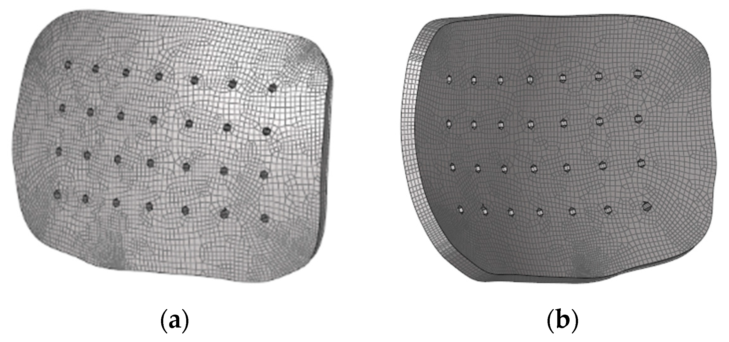
The process of meshing the implant was performed with the software Hypermesh. Firstly, a 2D mesh was created on the exterior surface of the implant with square elements of approximately 1.2 mm in size. Next, an offset was made to create 3D elements. This offset consisted of four layers through the thickness of the implant, each layer being 1 mm in size. Since the geometry was not very complex, linear hexahedral elements were used to perform the mesh of the implant, given the fact that they allow for more accurate results. Reduced integration was employed to reduce the computational cost. Overall, the implant mesh contained 20,940 C3D8R elements and 27,285 nodes (Figure 2).
2.5. Head Model and Implant
Once the previous steps of creating the skull defect and the implant mesh were completed, all parts (brain, BV and SSS, CSF, skull, and implant) were assembled on Abaqus to prepare the model for further numerical simulations. This assembly contained a total of 120,8740 elements.
2.6. Numerical Modeling Strategies
2.6.1. Fixation Method
Based on what was explained previously, the chosen fixation method in this work was tangential screws. Since modeling the geometry of the screws, their material properties, and their interaction with the other parts is an arduous task, the option was to employ the tool Fasteners from the Abaqus toolbox to represent the effect of the screw. This tool consists of a mesh-independent connection between surfaces that connect two or more parts using attachment lines and connectors that define the fastener location. These attachment lines are created by projecting the reference point to the closest surfaces selected. The connection between the connector and the nodes located nearby is accomplished by coupling the displacement and rotation of the connector element nodes and the average displacement and rotation of the nodes located inside a radius of influence. The radius of influence assigned was 1 mm.
Concerning the properties of the Fasteners tool, Korolija [27] made a parametric study to find out the best connector type to be associated with the attachment lines and the mechanical behavior that best represented titanium screws. The author opted for comparing only beam elements and connector elements. Beam elements are reported to work well with geometries modeled with shell elements. Still, when it comes to solid elements, they can be problematic due to the lack of rotational degrees of freedom. Therefore, connector elements were associated with the attachment lines, bushing elements more specifically. Furthermore, elastoplastic constitutive behavior was given to the connector element based on experiments made by Huth [28], assigning force-displacement characteristics. The linear elastic constitutive behavior of the connector elements was based on Huth’s experiments [25], that is, 185,051 N/mm as the applied stiffness in the load direction (all other directions defined as rigid). Table 2 include the values of the elastic and plastic behaviors, respectively, as defined by Huth’s experiment.
To define the number of screws and their diameter, the advice of the InterFix technology was employed. This technology recommends using five to nine screws for a large implant, so in this work, a parametric study was carried out to find the best configuration of the screws.
2.6.2. Numerical Modeling Strategies
Based on what was assumed on the head model used in this work [25], a frictionless general contact between all parts is maintained because the tangential behavior is not the most relevant factor in the studies carried out and this eases the computational cost.
All the numerical simulations were dynamic explicit analyses, which allows solving problems associated with complex deformable bodies, including inertial effects. Theoretically, the computational cost of an increment in the explicit analysis is lower than in implicit analysis. However, time increments in the explicit analysis have to be very small for the stability of the method and reliability of the solution to be maintained.
All the impacts simulated were representative of falls, so a rigid plate, modeled as an analytical rigid part, was assembled on the model simulating the ground. Instead of defining the velocity on the head model, it was defined on the rigid plate, and the head model had no boundary conditions. Figure 3 shows an image of the assembly containing the head model and the rigid plate.
2.6.3. Case Study I
A parametric study was performed to determine the number of screws that optimize the model. The presence of screws leads to stress concentration in nearby regions. An increase in the number of screws along the interface between the implant and the skull bone can reduce those high-stress concentrations, preventing the failure of both implant and skull bone. However, reducing the number of screws to the lowest possible is convenient to lower the costs, the number of external bodies, and the procedure’s complexity. Also, the displacement of the implant and the relative displacement between skull and implant are essential parameters to take into account, because the higher the displacement, the higher the risk of inducing brain injuries by direct trauma. For this purpose, an impact study was selected involving a fall from a bed scenario. As Schulz et al. [29] reported, for an impact load of 4.2 m/s, the normal component to the ground of the head velocity stands between 3.44 m/s and 3.86 m/s. Therefore, a velocity of 3.5 m/s was defined for an impact occurring on the central zone of the implant. Then three criteria were compared: von Mises stress field on the model, displacement field on the model, and maximum values of displacement and von Mises stress on both implant and skull bone interfaces.
2.6.4. Case Study II
Given the fact that the primary function of the cranial implant is to restore the skull’s protective function, it is imperative to evaluate the brain’s integrity after the implant is subjected to an impact load. Thus, a comparative study considered two scenarios: an impact load on the model with the implant and the same impact load on the same location on the model with an integral skull. The selected impact load describes a bicycle accident previously simulated by Fahlstedt et al. [30]. The authors obtained a linear velocity of 5.3 m/s, with a normal component to the ground of 4 m/s, which has served as a reference in this model.
Based on what was discussed previously about TBI and taking into account the information in Table 3, a compilation made by Tse et al. [31] containing a set of criteria related to mechanical variables that allow the measuring of TBI [4], the following parameters were evaluated on the brain:
- pressure;
- shear stress;
- von Mises stress;
- strain.
3. Results and Discussion
3.1. Case Study I
The maximum values of von Mises stress and displacement were nearly identical in all models except the one with five screws, which delivered higher peak stresses nearby the placed screws. As expected, high stresses were verified in the zone where the impact occurs. Furthermore, the holes situated near the impact zone led to increased stress concentrations near these holes, which is explained by the principles of fracture mechanics. Another element that is implicit in these results is that the maximum von Mises stresses verified in the model are in different zones depending on the number of the screws. For the models with five, six, and seven screws, the maximum von Mises stress was in the implant near the interface between implant and skull, while for the models with eight and nine screws, the maximum von Mises stress was in the region nearby the impact zone. This is a piece of clear evidence that, as expected, the number of screws is a parameter that may significantly change the stress field on the regions nearby the interface between implant and skull. The higher the number of screws, the lower the stress concentrations in the interface. Figure 4 contains the von Mises stress fields of the different models.
When it comes to the displacement, Figure 5 shows that it is impossible to minimize the maximum displacement in the impact zone, whatever the number of screws in use. This happens because, in the region where the impact occurs, the influence of the screws and the interface contact can be neglected, mainly because it is a very central zone of the implant. However, significant differences were verified in the displacement of the interface between implant and skull; the higher the number of screws, the lower the displacement verified in this region.
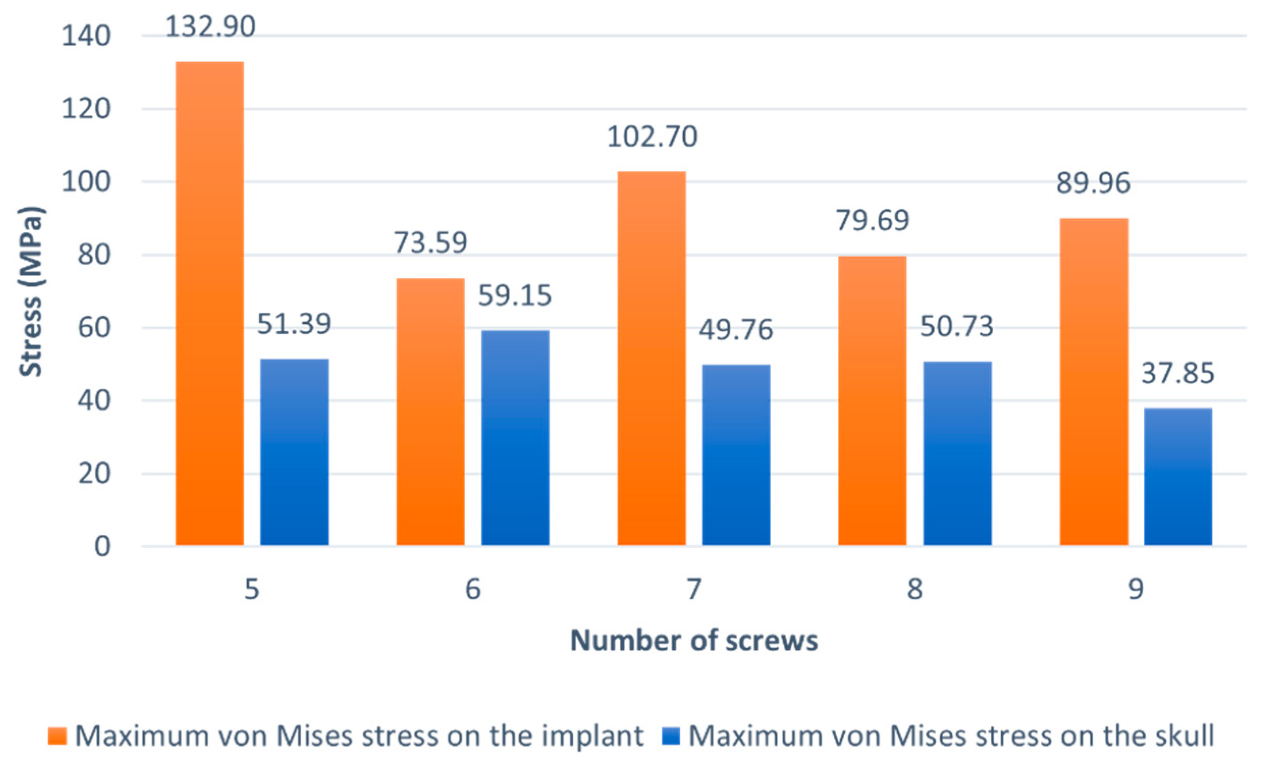
The graphic of Figure 6 exhibits the maximum values of von Mises stress obtained for the implant and the skull, respectively, for the various models studied. For the implant, and as mentioned early, the maximum stresses were obtained near the interface between implant and skull for the cases when five, six, and seven screws were used. In contrast, the maximum von Mises stress was obtained near the impact region in the other two cases. Recording the material constitutive behavior, the initial yield strength at a quasi-static strain rate was 132 MPa. This stress value was outdated only in the model with five screws, which reinforces the reasoning presented.
In short, two critical zones can be identified: the region nearby the impact and the interface between the implant and skull. Since changing the number of screws does not modify the behavior of the central zone of the implant where the impact occurs, the key for choosing the best option is to consider the von Mises stress and displacement near the interface between bone and implant. The models with six, eight, and nine screws are preferable regarding the von Mises stress. However, the significant displacements verified for the model with six screws ranging from the central zone to the interface are a possible explanation that the stresses are lower in these regions and make this model unusable. Since the models with eight and nine screws provide identical solutions and, as mentioned earlier, the lower the number of screws, the better, the model used in the further analysis is the one with eight screws.
Additionally, the stresses along the interface of bone and implant were subject to analysis to better understand the effect of the screws on stress concentration. A path was created in the software Abaqus containing a sequence of nodes, as shown in Figure 7a. The graphic of Figure 7b shows the evolution of the von Mises stress along the path selected. As is observable, the regions where the screws are located are almost always in local maximums, as expected. However, there are other regions in which higher stress values are registered. This happens mainly because of geometry conditions in the contact between bone and implant, since the mesh is irregular in some parts of the skull’s defect border.
3.2. Case Study II
In contrast to what could be expected, the values observed in Table 4 suggest, under these specific circumstances, that the implanted skull could be more effective when it comes to protecting the brain than the integral skull. To better understand these results, it is worth remembering that brain injury is a combination of two factors: deformation processes due to brain motion and direct trauma by indentation processes on the skull or implant. In fact, the material properties of both implant and cortical bone are decisive, because the lower stiffness of the implant material increases the damping effect and, consequently, decreases brain motion. On the contrary, this same damping effect can cause a traumatic injury to the brain region near the impact zone. This phenomenon is observed in Figure 8 and Figure 9, where, for the models with the implant, higher values of the parameters are registered on the impact zone due to the indentation effect, while for the models with an integral skull, the higher values of the parameters are distributed along the hemisphere. The parameter that most differed between the two models was the pressure, which makes it evident that brain motion influences this parameter much more than the more significant deflection of the implant.
4. Conclusions
In this work, a cranial implant was the subject of a numerical analysis in terms of mechanical resistance and brain protection. The main conclusion, in a nutshell, is that PEEK material, constantly referred to as the best material for such purposes, proved to be the best choice as the material to be assigned to the implant.
The limitations of the study are related to its numerical nature. Additionally, the results are valid only for the chosen implant geometry and location, as well as the impact conditions studied. Therefore, results must be viewed in such context. The numerical simulations involved a finite element human head model with an integrated implant and were divided into two parts:
- a parametric study which had the purpose of finding the best configuration of fixation screws, in terms of number, that optimized the mechanical performance of the model and the structural integrity of the implant;
- a comparative study between a model with a cranial implant and another with an integral skull to evaluate the implant’s capacity to protect the brain against TBI.
Relatively to the first part of the analysis, the structural integrity of the implant was maintained in almost all the configurations, except the one with five screws. The solutions with eight and nine screws proved to be the better setups, since they could reduce the localized von Mises stress and the displacements at the interface between the implant and skull, which is one of the critical zones. The evolution of the stresses along the implant interface showed local maximums on the regions nearby the screws’ locations. In the second part of the analysis, the model with the implant showed a greater capacity to protect the brain against TBI for all parameters evaluated, since less percentage of brain tissue was at risk of suffering moderate or severe injuries. For the particular conditions analyzed, the reason is related to the more flexible mechanical properties of the implant material when compared to cortical bone. Since PEEK has a lower stiffness (resulting from a lower Young’s modulus), a damping effect was verified, reducing brain motion. Overall, the modeled cranial implant and the options made during the modeling process proved to have great results since the main goals of the work were accomplished, specifically the development of a cranial implant that, when subjected to impact load, retains its structural integrity and ensures brain protection.
Author Contributions
Conceptualization, P.O.S.; formal analysis and funding acquisition, R.J.A.d.S.; investigation and methodology, F.A.O.F. and M.P.; test implementation, P.O.S.; validation and writing—original draft preparation, P.O.S.; writing—review and editing, P.O.S., G.P.C., M.P. and F.A.O.F. All authors have read and agreed to the published version of the manuscript.
Funding
Ricardo J. Alves de Sousa and Fábio A.O. Fernandes acknowledge the support of the Fundação para a Ciência e a Tecnologia (FCT) with the projects UIDB/00481/2020 and UIDP/00481/2020; and CENTRO-01-0145-FEDER-022083—Centro Portugal Regional Operational Programme (Centro2020), under the PORTUGAL 2020 Partnership Agreement, through the European Regional Development Fund.
Institutional Review Board Statement
Not applicable.
Informed Consent Statement
Not applicable.
Data Availability Statement
Data are contained within the article.
Conflicts of Interest
The authors declare no conflict of interest.
References
- Becker, C. Skull: Anatomy, structure, bones, quizzes. Available online: https://www.kenhub.com/en/library/anatomy/the-skull (accessed on 1 November 2021).
- Evans, K. Physiology of cortical and trabecular bone. In The Diagnosis and Treatment of Osteoporosis; Van-Griner: Ohio, OH, USA, 2012; pp. 12–27. [Google Scholar]
- Ptak, M.; Ratajczak, M.; Kwiatkowski, A.; Sawicki, M.; Wilhelm, J.; Fernandes, F.A.; Druszcz, A. Investigation of biomechanics of skull structures damages caused by dynamic loads. Acta Bioeng. Biomech. 2018, 20, 143–150. [Google Scholar] [CrossRef]
- Garcia-Gonzalez, D.; Jayamohan, J.; Sotiropoulos, S.N.; Yoon, S.H.; Cook, J.; Siviour, C.R.; Arias, A.; Jérusalem, A. On the mechanical behaviour of PEEK and HA cranial implants under impact loading. J. Mech. Behav. Biomed. Mater. 2017, 69, 342–354. [Google Scholar] [CrossRef]
- Huys, S.E.F.; van Gysel, A.; Mommaerts, M.Y.; Sloten, J.V. Evaluation of Patient-Specific Cranial Implant Design Using Finite Element Analysis. World Neurosurg. 2021, 148, 198–204. [Google Scholar] [CrossRef]
- Bonda, D.; Manjila, S.; Selman, W.; Dean, D. The Recent Revolution in the Design and Manufacture of Cranial Implants: Modern Advancements and Future Directions. Physiol. Behav. 2016, 176, 139–148. [Google Scholar] [CrossRef] [Green Version]
- Ma, H.; Suonan, A.; Zhou, J.; Yuan, Q.; Liu, L.; Zhao, X.; Lou, X.; Yang, C.; Li, D.; Zhang, Y.G. PEEK (Polyether-ether-ketone) and its composite materials in orthopedic implantation. Arab. J. Chem. 2021, 14, 102977. [Google Scholar] [CrossRef]
- Zhang, J.; Tian, W.; Chen, J.; Yu, J.; Zhang, J.; Chen, J. The application of polyetheretherketone (PEEK) implants in cranioplasty. Brain Res. Bull. 2019, 153, 143–149. [Google Scholar] [CrossRef]
- Najeeb, S.; Zafar, M.S.; Khurshid, Z.; Siddiqui, F. Applications of polyetheretherketone (PEEK) in oral implantology and prosthodontics. J. Prosthodont. Res. 2016, 60, 12–19. [Google Scholar] [CrossRef] [PubMed]
- Alqurashi, H.; Khurshid, Z.; Syed, A.U.Y.; Habib, S.R.; Rokaya, D.; Zafar, M.S. Polyetherketoneketone (PEKK): An emerging biomaterial for oral implants and dental prostheses. J. Adv. Res. 2021, 28, 87–95. [Google Scholar] [CrossRef] [PubMed]
- Zafar, M.S. Prosthodontic Applications of Polymethyl Methacrylate (PMMA): An Update. Polymers 2020, 12, 2299. [Google Scholar] [CrossRef]
- Huang, M.T.; Juan, P.K.; Chen, S.Y.; Wu, C.J.; Wen, S.C.; Cho, Y.C.; Huang, M.S.; Chou, H.H.; Ou, K.L. The potential of the three-dimensional printed titanium mesh implant for cranioplasty surgery applications: Biomechanical behaviors and surface properties. Mater. Sci. Eng. C 2018, 97, 412–419. [Google Scholar] [CrossRef] [PubMed]
- Elhattab, K.; Sikder, P.; Walker, J.M.; Bottino, M.C.; Bhaduri, S.B. Fabrication and evaluation of 3-D printed PEEK scaffolds containing Macropores by design. Mater. Lett. 2020, 263, 127227. [Google Scholar] [CrossRef]
- de Santis, R.; Russo, T.; Rau, J.V.; Papallo, I.; Martorelli, M.; Gloria, A. Design of 3d additively manufactured hybrid structures for cranioplasty. Materials 2021, 14, 181. [Google Scholar] [CrossRef] [PubMed]
- Roque, R.; Barbosa, G.F.; Guastaldi, A.C. Design and 3D bioprinting of interconnected porous scaffolds for bone regeneration. An additive manufacturing approach. J. Manuf. Process. 2021, 64, 655–663. [Google Scholar] [CrossRef]
- Jonkergouw, J.; van de Vijfeijken, S.E.; Nout, E.; Theys, T.; Van de Casteele, E.; Folkersma, H.; Depauw, P.R.; Becking, A.G. Outcome in patient-specific PEEK cranioplasty: A two-center cohort study of 40 implants. J. Cranio-Maxillofac. Surg. 2016, 44, 1266–1272. [Google Scholar] [CrossRef] [PubMed]
- Rashidi, A.; Adolf, D.; Karagiannis, D.; Melhem, O.B.; Luchtmann, M. Incidence and Risk Factors for Skull Implant Displacement After Cranial Surgery. World Neurosurg. 2019, 126, e814–e818. [Google Scholar] [CrossRef] [PubMed]
- Garcia-Gonzalez, D.; Rusinek, A.; Jankowiak, T.; Mechanical, A.A. Mechanical impact behavior of polyether-ether-ketone (PEEK). Compos. Struct. 2015, 124, 88–99. [Google Scholar] [CrossRef] [Green Version]
- Rae, P.J.; Brown, E.N.; Orler, E.B. The mechanical properties of poly(ether-ether-ketone) (PEEK) with emphasis on the large compressive strain response. Polymer 2007, 48, 598–615. [Google Scholar] [CrossRef]
- Johnson, G.R.; Cook, W.H. Fracture characteristics of three metals subjected to various strains, strain rates, temperatures and pressures. Eng. Fract. Mech. 1985, 21, 31–48. [Google Scholar] [CrossRef]
- Sobieraj, M.; Rimnac, C. Fracture, Fatigue, and Notch Behavior of PEEK. In PEEK Biomaterials Handbook; Elsevier: Amsterdam, Netherlands, 2012; pp. 61–73. [Google Scholar]
- Fernandes, F.A.O.; Tchepel, D.; de Sousa, R.J.A.; Ptak, M. Development and validation of a new finite element human head model: Yet another head model (YEAHM). Eng. Comput. 2018, 35, 477–496. [Google Scholar] [CrossRef]
- Migueis, G.F.J.; Fernandes, F.A.O.; Ptak, M.; Ratajczak, M.; de Sousa, R.J.A. Detection of bridging veins rupture and subdural haematoma onset using a finite element head model. Clin. Biomech. 2019, 63, 104–111. [Google Scholar] [CrossRef]
- Costa, J.M.C.; Fernandes, F.A.O.; de Sousa, R.J.A. Prediction of subdural haematoma based on a detailed numerical model of the cerebral bridging veins. J. Mech. Behav. Biomed. Mater. 2020, 111, 103976. [Google Scholar] [CrossRef]
- Barbosa, A.; Fernandes, F.A.O.; de Sousa, R.J.A.; Ptak, M.; Wilhelm, J. Computational modeling of skull bone structures and simulation of skull fractures using the YEAHM head model. Biology 2020, 9, 267. [Google Scholar] [CrossRef] [PubMed]
- Marcián, P.; Narra, N.; Borák, L.; Chamrad, J.; Wolff, J. Biomechanical performance of cranial implants with different thicknesses and material properties: A finite element study. Comput. Biol. Med. 2019, 109, 43–52. [Google Scholar] [CrossRef]
- Korolija, A. FE-Modeling of Bolted Joints in Structures; Linköping University: Linkoping, Sweden, 2012. [Google Scholar]
- Huth, H. Experimenal Determination of Fastener Flexibilities; Aircraft Division Saab-Scania AB: Linköping, Sweden, 1983. [Google Scholar]
- Schulz, B.W.; Lee, W.E.; Lloyd, J.D. Estimation, simulation, and experimentation of a fall from bed. J. Rehabil. Res. Dev. 2008, 45, 1227–1236. [Google Scholar] [CrossRef] [PubMed]
- Fahlstedt, M.; Baeck, K.; Halldin, P.; Van Der Sloten, J.; Goffin, J.; Depreitere, B.; Kleiven, S. Influence of impact velocity and angle in a detailed reconstruction of a bicycle accident. In Proceedings of the 2012 IRCOBI Conference Proceedings—International Research Council on the Biomechanics of Injury Conference, Dublin, Ireland, 12–14 September 2012; pp. 787–799. [Google Scholar]
- Tse, K.M.; Tan, L.B.; Lee, S.J.; Lim, S.P.; Lee, H.P. Investigation of the relationship between facial injuries and traumatic brain injuries using a realistic subject-specific finite element head model. Accid. Anal. Prev. 2015, 79, 13–32. [Google Scholar] [CrossRef]
Figure 1.
Creation of the skull defect: (a) skull after elements were deleted; (b) skull after the projection of the border elements; (c) final skull model after the deletion of the poor elements on the defect’s border.
Figure 1.
Creation of the skull defect: (a) skull after elements were deleted; (b) skull after the projection of the border elements; (c) final skull model after the deletion of the poor elements on the defect’s border.

Figure 2.
Different views of the implant mesh: (a) exterior surface; (b) interior surface.

Figure 3.
The assembly containing the head model and the rigid plate.

Figure 4.
Von Mises stress fields for the models with different screws configurations [MPa]: (a) configuration with five screws; (b) configuration with six screws; (c) configuration with seven screws; (d) configuration with eight screws; (e) configuration with nine screws.
Figure 4.
Von Mises stress fields for the models with different screws configurations [MPa]: (a) configuration with five screws; (b) configuration with six screws; (c) configuration with seven screws; (d) configuration with eight screws; (e) configuration with nine screws.

Figure 5.
Displacement field for the models with different screws configuration [mm]: (a) configuration with five screws; (b) configuration with six screws; (c) configuration with seven screws; (d) configuration with eight screws; (e) configuration with nine screws.
Figure 5.
Displacement field for the models with different screws configuration [mm]: (a) configuration with five screws; (b) configuration with six screws; (c) configuration with seven screws; (d) configuration with eight screws; (e) configuration with nine screws.

Figure 6.
Maximum von Mises stress verified on the implant and the skull for the various models.

Figure 7.
Analysis of the stress evolution along with the interface between skull and implant: (a) path along with the interface between skull and implant; (b) von Mises stress evolution along the path, with the locations of the screws highlighted by the red bars.
Figure 7.
Analysis of the stress evolution along with the interface between skull and implant: (a) path along with the interface between skull and implant; (b) von Mises stress evolution along the path, with the locations of the screws highlighted by the red bars.

Figure 8.
Von Mises stress on the brain for both models [MPa]: (a) model with the implant; (b) model with an integral skull.
Figure 8.
Von Mises stress on the brain for both models [MPa]: (a) model with the implant; (b) model with an integral skull.

Figure 9.
Displacement of the brain for both models [mm]: (a) model with the implant; (b) model with an integral skull.
Figure 9.
Displacement of the brain for both models [mm]: (a) model with the implant; (b) model with an integral skull.


Table 1.
Properties used to define the thermoviscoplastic behavior of PEEK [18].
Table 1.
Properties used to define the thermoviscoplastic behavior of PEEK [18].
| Thermoviscoplastic Behavior | |||||
| A (MPa) | B (MPa) | n | (s−1) | C | m |
| 132 | 10 | 1.2 | 0.01 | 0.034 | 0.7 |
| Elasticity | Other Physical Constants | ||||
| E0 (GPa) | ν | (kg/m3) | β | Cp (J/kg K) | Tm (K) |
| 3.6 | 0.4 | 1304 | 0.9 | 2180 | 614 |
Table 2.
Plastic constitutive behavior of the connector elements based on Huth’s experiments [28].
Table 2.
Plastic constitutive behavior of the connector elements based on Huth’s experiments [28].
| Force (Each Screw) [N] | Relative Plastic Displacement [mm] |
|---|---|
| 1000 | 0.000 |
| 2000 | 0.005 |
| 4000 | 0.020 |
| 6000 | 0.080 |
| 9000 | 0.225 |
| 11,000 | 0.400 |
| 13,000 | 0.640 |
Table 3.
Threshold of brain injury criteria [31].
Table 3.
Threshold of brain injury criteria [31].
| Parameter | Thresholds |
|---|---|
| Pressure | Criterion 1 |
| >235 kPa→injury | |
| <173 kPa→minor or no injury | |
| Shear stress | Criterion 2 |
| 11–16.5 kPa→severe injury | |
| Von Mises stress | Criterion 3 |
| >18 kPa→50% probability of moderate neurological lesions | |
| >38 kPa→50% probability of severe neurological lesions | |
| Criterion 4 | |
| ≥26 kPa→axonal damage | |
| Strain | Criterion 5 |
| >0.25→structural damage | |
| >0.20→functional damage | |
| >0.10→reversible damage |
Table 4.
Percentage of brain tissue within the thresholds that match the criteria defined.
| Criterion | Criterion Definition | Model With Implant | Model With Integral Skull |
|---|---|---|---|
| Criterion 1 | Injury | 0.29% | 5.88% |
| Minor or No Injury | 99.13% | 84.28% | |
| Criterion 2 | Severe Injury (Shear stress XY) | 0.010% | 0.018% |
| Severe Injury (Shear Stress XZ) | 0.002% | 0.025% | |
| Severe Injury (Shear Stress YZ) | 0.001% | 0.026% | |
| Criterion 3 | 50% Probability of Moderate Neurological Lesions | 2.47% | 1.84% |
| 50% Probability of Severe Neurological Lesions | 0.01% | 0.12% | |
| Criterion 4 | Axonal Damage | 0.40% | 0.48% |
| Criterion 5 | Reversible Damage | 0.35% | 0.49% |
| Functional Damage | 0.001% | 0.01% | |
| Axonal Damage | 0.001% | 0.01% |
Publisher’s Note: MDPI stays neutral with regard to jurisdictional claims in published maps and institutional affiliations. |
© 2022 by the authors. Licensee MDPI, Basel, Switzerland. This article is an open access article distributed under the terms and conditions of the Creative Commons Attribution (CC BY) license (https://creativecommons.org/licenses/by/4.0/).
Share and Cite
MDPI and ACS Style
Santos, P.O.; Carmo, G.P.; Sousa, R.J.A.d.; Fernandes, F.A.O.; Ptak, M. Mechanical Strength Study of a Cranial Implant Using Computational Tools. Appl. Sci. 2022, 12, 878. https://0-doi-org.brum.beds.ac.uk/10.3390/app12020878
AMA Style
Santos PO, Carmo GP, Sousa RJAd, Fernandes FAO, Ptak M. Mechanical Strength Study of a Cranial Implant Using Computational Tools. Applied Sciences. 2022; 12(2):878. https://0-doi-org.brum.beds.ac.uk/10.3390/app12020878
Chicago/Turabian StyleSantos, Pedro O., Gustavo P. Carmo, Ricardo J. Alves de Sousa, Fábio A. O. Fernandes, and Mariusz Ptak. 2022. "Mechanical Strength Study of a Cranial Implant Using Computational Tools" Applied Sciences 12, no. 2: 878. https://0-doi-org.brum.beds.ac.uk/10.3390/app12020878
Note that from the first issue of 2016, this journal uses article numbers instead of page numbers. See further details here.