

Research on Electrochemical Controllable Machining Technology of Small-Sized Inner Intersecting Hole Rounding
College of Mechanical Engineering and Automation, Dalian Polytechnic University, No. 1, Qinggongyuan, Ganjingzi District, Dalian 116034, China
*
Authors to whom correspondence should be addressed.
Appl. Sci. 2022, 12(20), 10666; https://0-doi-org.brum.beds.ac.uk/10.3390/app122010666
Submission received: 29 September 2022
/
Revised: 12 October 2022
/
Accepted: 18 October 2022
/
Published: 21 October 2022
(This article belongs to the Special Issue Precision Manufacturing and Intelligent Machine Tools)
Abstract
:Small-sized inner intersecting holes are a common structure for large engine nozzles, hydraulic valves, and other parts. In order to ensure the uniform and stable fluid state in the intersecting hole, it is necessary to process the fillet at the intersecting line and accurately control the fillet radius. Limited by the structure and size, the rounding of the small-sized inner intersecting hole is a technical problem, and the traditional machining methods have problems, in terms of efficiency and accuracy. In order to solve this problem, electrochemical machining technology was applied to the rounding of small-sized inner intersecting holes. According to the structure of inner intersecting holes, an electrochemical rounding processing scheme with built-in fixed cathode was designed. The electric field distribution of different cathode shapes was analyzed using finite element method software. The influence of processing voltage and processing time on the current density distribution was studied for different cathode shapes, to determine the most reasonable cathode shape. Taking the inner intersecting hole with a diameter of 2 mm as the research object, and according to the analysis of the influence of processing voltage on the processing effect, a suitable control factor for controlling the rounding was processing time, and the optimal processing voltage was obtained. The formulas of fillet radius and processing time were obtained by regression analysis and verified using machining examples. The results provide a feasible method for the accurate and controllable machining of small-sized inner intersecting hole rounding.
1. Introduction
Small intersecting holes are a common structure in large engine nozzles, hydraulic valves, and other parts [1,2]. When the fluid medium flows through the pipeline, in order to make the medium flow evenly and smoothly, avoid incrustation, and ensure the stable operation of the system, it is not only necessary to remove the burrs from the intersecting lines, but also more precise rounding is needed for some high-performance parts, to reduce the blocking at the intersecting line of the intersecting hole, reduce the energy loss, and improve the reliability and accuracy of the fluid system [3,4]. Restricted by the structure and size of the inner intersecting hole, accurate and controllable rounding of the intersecting line is a difficult problem. At present, the methods for improving the shape of the intersecting line mainly include mechanical machining [5,6], abrasive waterjet machining [7,8], ultrasonic machining [9], magnetic abrasive machining, and electrochemical machining [10,11]. Electrochemical machining is non-contact machining, which has the advantages of not being restricted by material hardness, a good surface quality after machining, and high machining efficiency, and it is more suitable for the machining of difficult structures, such as the intersecting line of pinholes, thin tube inner walls, and blades [12,13,14]. Zhao et al. [15] used electrochemical finishing on the inner surface of deep holes after additive manufacturing. The Ra value of the inner surface roughness of the deep holes decreased from 15.991 μm to 10.396 μm, and the Rz value of the surface roughness decreased from 84.226 μm to 54.962 μm. Li et al. [16] conducted a multi-physical field coupling simulation on electrochemical machining in film cooling holes. The results showed that pulsed electrochemical machining improved the temperature distribution and current density of the machining area, which improved the accuracy and stability of electrochemical machining in the holes. Tang et al. [17] used a new pull downstream cathode structure to process a large-diameter special-shaped inner spiral tube, effectively improving the uniformity of the electrolyte flow field and improving the surface quality. Wang et al. [18] improved the flow field and processing positioning using a synchronous pulse current and low-frequency oscillations, thus reducing the stray corrosion on the side wall of rhomboid holes. Zhang et al. [19] optimized the cathode shape of electrochemical machining for small inner-walled ring grooves of 1J116 material, and adopted an optimized cathode shape to effectively change the flow field distribution during the machining process and improved the surface quality.
The above research shows that electrochemical machining can effectively improve the surface quality and shape accuracy of special-shaped parts, but it has strict requirements for the design of the cathode structure and the distribution of the flow field in the machining [20,21]. The electrochemical machining processes of intersecting holes, deep holes, and through-holes are affected by physical fields, such as the flow field and electric field [22]. The finite element simulation method has been used to explore the physical field characteristics in the machining process, to predict the workpiece formation condition, which can shorten the cathode development cycle and reduce the manufacturing cost [23,24,25]. Lin et al. [26] used finite element simulation to optimize the design of a cathode for machining complex parts with multi-stage internal cone holes and verified through experiments that the gap and flow field of the cathode with a cone angle of 2° were evenly distributed during the machining process. Chai et al. [27] developed and analyzed the flow path of the gap flow field geometry model based on a CFD simulation of electrolyte flow state, and determined the influence of the flow field on the accuracy and stability of the cooling hole manufacturing process. Jia et al. [28] used COMSOL simulation software to optimize the cathode shape in the electrochemical machining process of square deep holes and optimized the combination of processing parameters through gray relational analysis, which successfully solved the technical problem of electrochemical machining of square deep holes. The intersecting hole was a typically shaped hole, and the electrochemical machining of the inner intersecting hole could be generally divided into two categories: one is deburring, the other is shape machining. Choi et al. [29] inserted a cylindrical cathode into a small hole intersecting with a large hole, and proposed an automatic electrolytic deburring method based on current detection, to deburr the intersecting hole with a diameter of 5 mm, and reducing the burr height of 0.9 mm to 0.15 mm. Zhang et al. [30] analyzed the deburring effect of different shapes of cathodes using a finite element method, and thickened the spherical and cylindrical tangent parts of hemispherical cathodes, to remove burrs in the intersecting holes with a diameter of 5 mm, which improved the machining efficiency and quality. Wang et al. [31] proposed a localized electrochemical deburring process using gel electrolytes, to reduce the burr height from 473.832 µm to 178.643 µm, effectively solving the problem of stray corrosion during electrochemical deburring. Kong [32] proposed a nested circle fitting method for the centering of micro-holes, aiming at the accuracy and stability of centering during the secondary processing of micro-holes, which could effectively remove the edge and surface burrs of micro-holes. Deburring can effectively improve the flow field characteristics of intersecting holes, but for some parts with special requirements, it cannot fully meet the requirements of use. Thus, it is necessary to round the intersection line of the intersecting holes. The processing of a fillet requires the cathode to form a special shape to meet the electric field distribution required for fillet formation. Shen et al. [33] used a cathode with an intersecting structure to study the deburring and arc modification of the intersecting line of the intersecting hole in a fuel injector. The radius of the transition arc was controlled to be 2 mm, and the radius error of the arc contour was about 10%.
At present, theoretical and experimental research on the electrochemical machining of intersecting lines of small intersecting holes has carried out beneficial explorations of deburring and formation, and some research has great application value. However, it remains a challenge to achieve accurate control of the fillet shape. The difficulties include the following: (1) In order to ensure the fillet shape, it is necessary to design a cathode with a special shape, to ensure a uniform and stable flow field in a small space. (2) The diameter of the intersecting hole restricts the size of the cathode. The current processing method is to insert the cathode from the small hole, and it is difficult to make a small-sized cathode with a special shape. (3) The gap state changes in real time during the machining process, and there is a linkage relationship between the machining gap, current density, and current efficiency. How to accurately consider the electric field distribution law is also a difficult problem.
In order to solve the above problems, this paper proposes a built-in fixed cathode electrochemical rounding technical scheme. By arranging the cathode opposite to the outside of the small intersecting hole, restriction of the diameter of the small intersecting hole on the shape of the cathode is removed from the processing method, and this is also conducive to the formation of a uniform and stable electrolyte flow field. Aiming at a dynamic change of the electric field distribution under the condition of a variable gap, the finite element method was used to simulate the electric field, and the influence law of the shape of the cathode and the machining voltage on the rounding process was obtained, and the appropriate shape of the cathode was selected accordingly. Taking a 304 steel material and small intersecting-hole parts with a diameter of 2 mm as research objects, the variation law of the fillet radius with the processing time was experimentally studied, and a mathematical model was established and verified using experiments. The research results provide a feasible solution for the controllable machining of the inner fillet of small intersecting holes, and also provide a reference for the electrochemically-controllable removal of materials under the condition of a variable gap.
2. Electrochemical Machining Scheme of an Inner Fillet
At present, the commonly used electrochemical rounding method for intersecting holes is shown in Figure 1a. The cylindrical cathode is inserted into the blind hole, and the part near the chamfer is in contact with the electrolyte, while the other parts are insulated. The cathode shape of this scheme is simple and easy to manufacture, but the problem is that, due to the limitation of the diameter of the intersecting hole, the rigidity of the cathode is insufficient, and it is difficult to process into a specific cathode shape. In addition, the cathode occupies the space in the small hole, which affects the flow of the electrolyte, making it difficult to accurately control the shape of the fillet. Therefore, a built-in fixed cathode electrochemical rounding scheme is proposed in this paper, as shown in Figure 1b. In this built-in fixed cathode electrochemical machining scheme, the cathode is outside the small hole, and the size is not limited by the hole diameter, which strengthens the rigidity of the cathode. In addition, if the insoluble electrolytic products generated in the machining process accumulate in the machining gap, this may cause a short circuit or even make it difficult to continue the processing, and the uneven flow field will lead to stray corrosion. A built-in fixed cathode electrochemical machining scheme can make the electrolytic products discharged in time, make the electrolyte flow field relatively uniform, and reduce the interference between the cathode position and the flow field, which can improve the processing stability and the molding accuracy of the fillet. A comparison of the two processing schemes is shown in Table 1. Using the built-in fixed cathode electrochemical rounding scheme to process the inner fillet of a small intersecting hole can avoid the shortcomings of the existing processing methods and is conducive to the realization of controllable processing.
3. Simulation Study of Cathode Shape
3.1. Cathode Shape Design
According to the requirements of fillet processing of inner intersecting hole, the ideal cathode shape is a concave shape that is opposite to the fillet shape. However, during the formation process of the fillet, the shape and size are constantly changing, and the state of the machining gap changes accordingly; thus, the final shape of the fillet is only approximate to the ideal shape. To achieve precise control of the radius of the fillet, the key is that the distribution of the electric field is conducive to the formation and control of the fillet during processing. At the same time, the electrode shape should also be considered for ease of processing. Therefore, four cathode shapes: cylindrical, conical, hemispherical, and concave, are designed in this paper, as shown in Figure 2 (only the chamfered parts of the workpiece are drawn in the figure). A reasonable cathode shape was determined by finite element simulation, as follows:
3.2. Influence of Cathode Shape on Machining
In this section, COMSOL Multiphysic software was used to analyze the electric field distributions corresponding to the four cathode structures, and the cathode shapes suitable for electrochemically controllable machining were obtained. Then, simulation analyses of the current density at different times and different voltages were carried out, and the variation law of the electrochemical fillet machining efficiency was obtained, which provided a reference for experimental research. The simulation parameters were as follows: the electrolyte temperature was 25 °C; the processing voltage was 10 V; the anode material was 304 stainless steel; the volume electrochemical equivalent was 2.09 mm3/A∙min [34]; the mass fraction of NaNO3 electrolyte was 15%, and its initial conductivity was 11.6 s/m; considering the influence of bubbles on electrical conductivity, the influence index was taken as 1.5 [35]; the current efficiency η and current density i satisfy Formula (1).
3.2.1. Influence of Cathode Shape on the Electric Field Distribution
In order to explore the electric field distribution during processing, simulations of current density distributions at different processing times were performed for the four cathode structures shown in Figure 2, and the results are shown in Table 2. With cylindrical and hemispherical cathodes, the anode surface was equipotential at the beginning of machining, and the electric field lines passed vertically through the surface of the anode. The curvature radius of the sharp corner at the intersecting line of the holes was small, and the density of the electric field line perpendicular to the surface was higher, which resulted in the greater electric field intensity and higher current density in this area. Therefore, at the beginning of processing, the current density as highly concentrated in the sharp corners of the workpiece, and the sharp corners were removed at a fastest rate, which was beneficial for improving the processing efficiency. However, after the fillets were formed, the current density distribution on the surface of the fillets was excessively concentrated in the middle of the fillets, and the formed fillets gradually became oblique corners. Using conical and concave cathodes, the current density was less concentrated on the chamfered part than with cylindrical and hemispherical cathodes. With machining, the sharp corners of the workpiece gradually formed fillets. With this process, the curvature radius of the chamfered part increased gradually, and the density of the electric field lines perpendicular to the surface decreased uniformly. As a result, the current density distribution on the surface of the formed fillets gradually became sparse and uniform, and the material removal speed of the chamfered parts was slowed, which was beneficial to accurately control the change of the fillet size during processing. Therefore, concave cathodes and conical cathodes are more suitable for electrochemically controllable machining of small intersecting-hole fillets.
3.2.2. Influence of Cathode Shape on Machining Efficiency
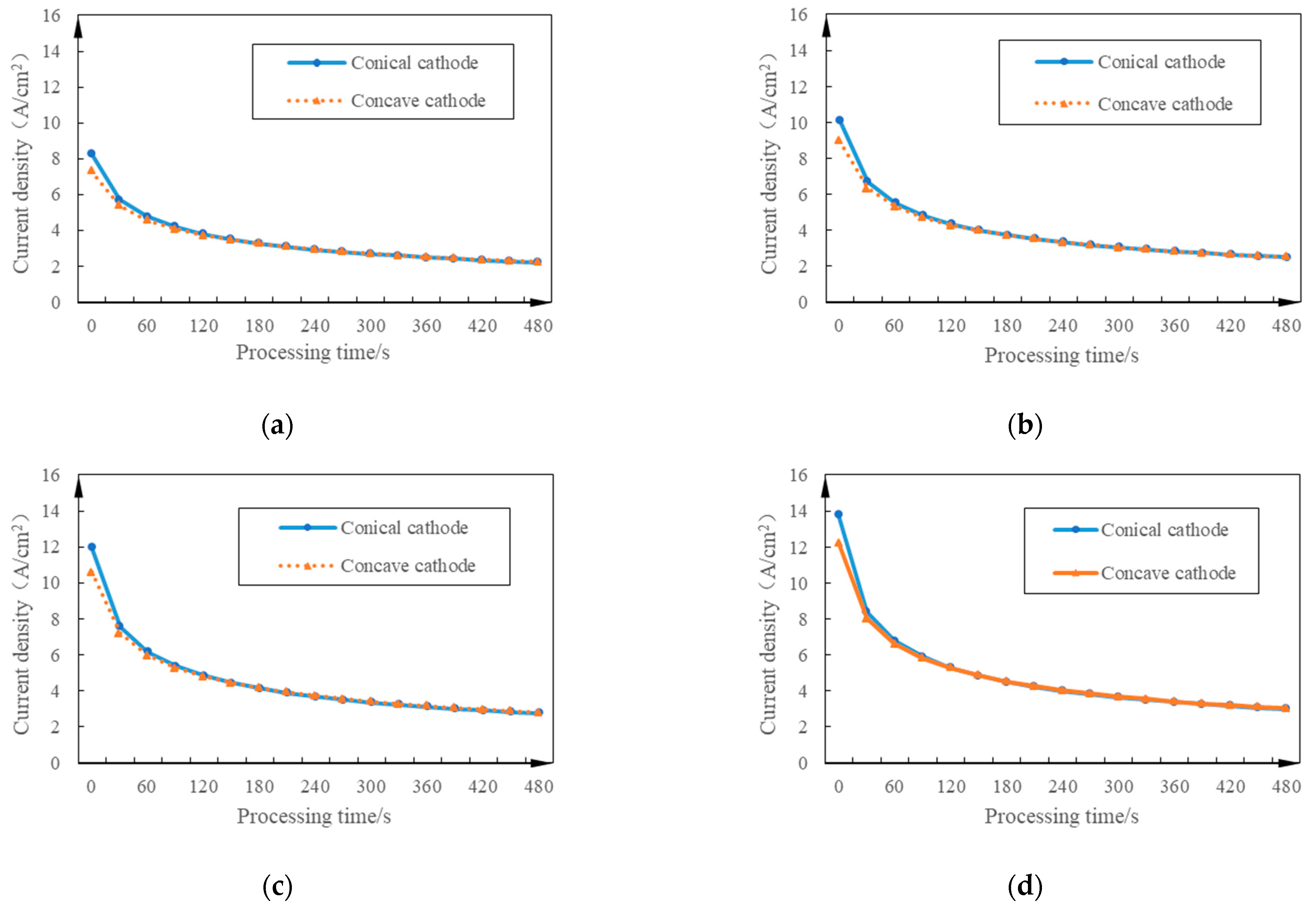
The machining efficiency of a fillet can be expressed by the maximum current density of the machined surface. As shown in Figure 3, for the conical and concave cathodes, the maximum current density on the surface of the workpiece is always at the minimum gap during machining. The simulation of the current density variation with time at the minimum gap of the machined surface under different voltage conditions was carried out, and the results are shown in Figure 4. In general, the efficiency was high at the beginning of the process and gradually decreased. At the beginning of processing, the current density of the conical cathode was higher, and the processing efficiency was slightly higher than that of the concave cathode. With continued processing, the changing laws of the two tended to become consistent, and the processing efficiencies were basically the same.
Considering the electric field distribution of different shapes of cathodes and the changes with time, conical cathodes and concave cathodes are suitable for the electrochemically controllable machining of small intersecting-hole fillets, and the machining efficiency of conical cathodes is slightly higher. At the same time, considering the manufacturing process, the conical cathodes are easier to process, so a conical cathode was used for the experimental research.
4. Experimental Research on the Electrochemical Machining of an Inner Fillet
4.1. Cathode Shape Design
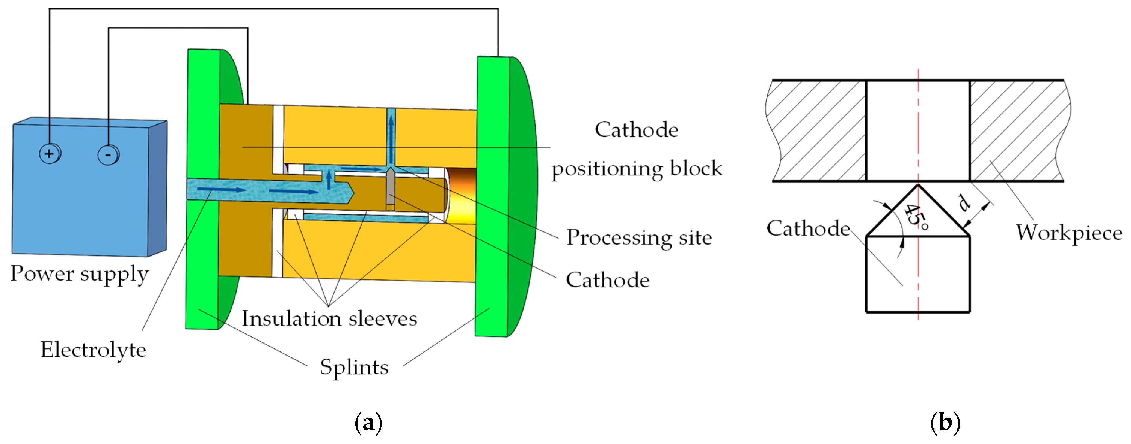
The experimental setup is shown in Figure 5. During processing, the workpiece was connected to the positive pole of the power supply, the tool was connected to the negative pole of the power supply, and the cathode was arranged opposite to the fillet to be processed. The electrolyte flows into the processing area from the central hole of the cathode positioning block, and flows uniformly from the periphery of the cathode, ensuring the stability of the flow field. The cathode part corresponding to the non-processed area of the workpiece was insulated by the insulating sleeve, and at the same time, it can fix the cathode and avoid cathode jitter.
4.2. Experimental Conditions
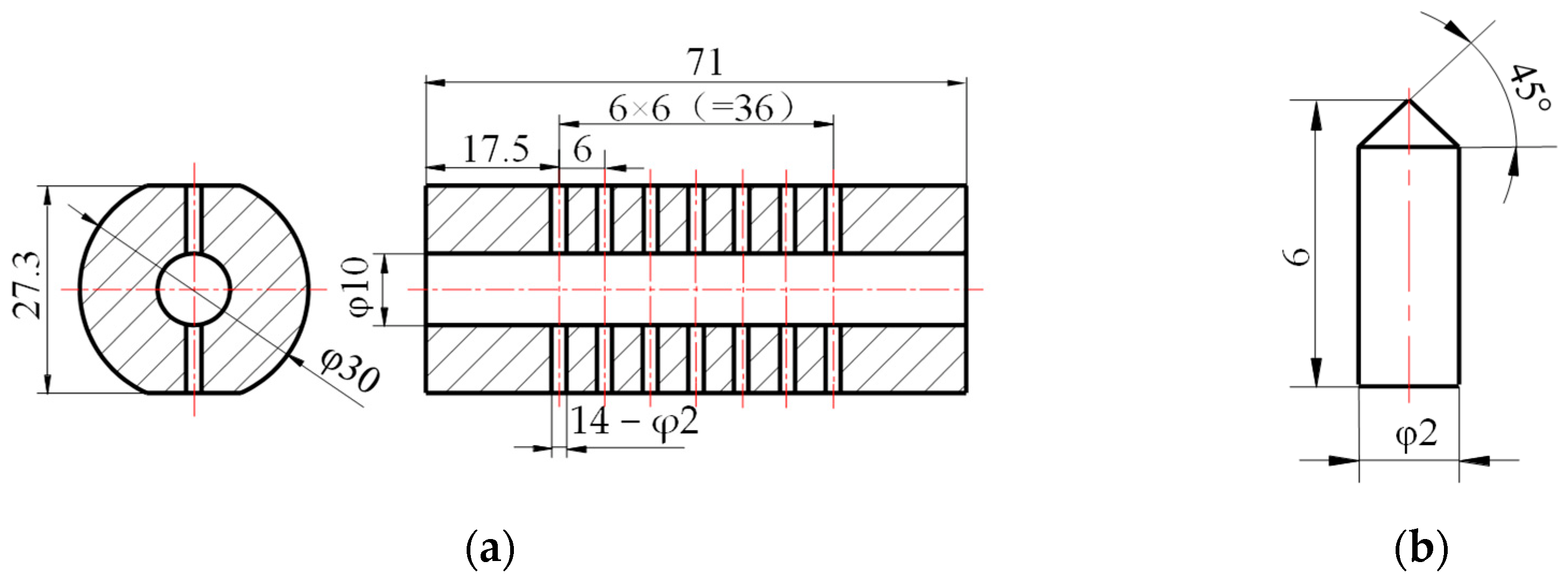
The experimental conditions were determined with reference to the process parameters obtained from the simulation, as shown in Table 3. In order to reduce the number of workpieces, the workpiece was designed as a multi-intersecting-hole structure, as shown in Figure 6a. An actual picture of the workpiece is shown in Figure 7. Electrochemical rounding with different machining times and machining voltages was performed on the intersection of small holes in the workpiece. After machining was completed, it was cut along the central axis of the holes, and the radius values were obtained.
4.3. Experimental Results and Discussion
4.3.1. Influence of Machining Voltage on the Machining Effect
The controlling factors of electrochemical rounding machining include the machining voltage (current) and machining time. First, the influence of machining voltage (current) on the machining effect was studied under the condition of a constant machining time. The machining time was set to 120 s, and the machining voltage was changed to carry out electrochemical rounding machining experiments. The experimental results are shown in Table 4. It can be seen from the table that when the voltage was increased to more than 10 V, the machining effect was too sensitive to changes in machining voltage, indicating that it would be difficult to realize the precise control of the rounded shape by adjusting the machining voltage. Under the premise of stable and controllable machining process and guaranteeing machining quality, the higher the machining voltage, the higher the machining efficiency of the fillets. Therefore, the selected machining voltage was 10 V, and the radius of the fillets was controlled by changing the machining time.
4.3.2. Fillet Radius as a Function of Processing Time
Under a 10 V machining voltage, the experimental results of the fillet radius for different machining times are shown in Figure 8. At the beginning of the processing, the fillet radius changed rapidly. As the processing progressed, the corner radius further increased, but the growth rate slowed down. The experimental law is basically consistent with the change law of the chamfering radius obtained from the simulation. At the beginning of processing, the tip effect at the intersecting line was significant, and the workpiece dissolved quickly. As the processing progressed, the intersecting lines formed fillets, the tip effect was weakened, the electrolytic product reduced the conductivity of the electrolyte, and the dissolution rate of the workpiece slowed down. When the processing time increased to 420 s, the fillet radius was greater than 1 mm, the chamfering processing efficiency became very low, and the fillet radius basically did not increase.
According to the variation law of the fillet radius with the processing time in Figure 8, it is speculated that the fillet radius may be approximately a quadratic function of the processing time. A 95% confidence was used, the experimental results were analyzed by quadratic regression, and the results are shown in Table 5. For univariate quadratic regression, this can be treated as a polynomial regression and the significance can be validated using an F-test. According to Table 5, the calculated F-statistic value is 1017.89. By querying the F-distribution function, when the significance level was 0.05, the first degree of freedom was 2, and the second degree of freedom was 13 and the standard F-statistic value was 3.81. The calculated F-statistic value of 1017.89 was much higher than the standard F-statistic value of 3.81, and the results of the regression analysis passed the F-test. The significance of the regression results was validated, and it can be seen that the fillet radius and the processing time satisfy the quadratic regression equation. The quadratic fitting relationship between the fillet radius R (mm) and the processing time t (s) is shown in Formula (2). According to the Formula (2), the processing time of the expected radius can be calculated, and a controllable chamfering processing of the small intersecting hole can be realized.
4.4. Processing Example
For the experimental workpiece shown in Figure 6a, the actual processing effect was verified according to the target fillet radius of 0.4 mm, 0.5 mm, 0.6 mm, 0.8 mm, and 1 mm. According to Formula (2), the processing time required for the corresponding fillet radius was calculated and rounded, as shown in Table 6.
According to the processing time in Table 6, the experiment was repeated three times, and the experimental results and errors are shown in Table 7. The processing effect of the first experiment is shown in Figure 9. During actual machining, due to the different burr states of the intersecting hole and the influence of cathode positioning errors, there was a certain error between the actual machining radius and the target radius. The maximum value of the error was 4.2%, the minimum value was 2.1%, and the average value was 2.9%.
5. Conclusions
Regarding the issue of small-sized inner intersecting hole fillet processing, this paper explored the influence law of machining parameters on the fillet radius through simulations and experimental research; based on which, a feasible method of electrochemically controllable chamfering was proposed. The main conclusions of this study are as follows:
(1) A built-in fixed cathode machining method is more suitable for the electrochemical rounding machining of small intersecting holes, which is conducive to forming a specific cathode shape and improving the stability of the flow field.
(2) A conical cathode not only has a good manufacturing process, but the law of electric field distribution change with time is also conducive to the formation and accurate control of fillets. At the beginning of processing, the concentration of the current density at the sharp corners of the workpiece is beneficial for improving the processing efficiency; and after the fillet is formed, the uniformity of the current density distribution is beneficial for accurately controlling of the fillet size.
(3) A built-in conical fixed cathode was adopted, and the radius of the small intersecting hole could be precisely controlled by adjusting the processing time. For the experimental specimens in this paper, using the processing parameters obtained by the established regression equation, the maximum error between the experimental value and the predicted value for different fillet radius within 1 mm was 4.2%. The minimum value as 2.1%, and the average value was 2.9%.
In further research, we will analyze the surface quality of the parts built with built-in conical fixed cathode for electrochemical chamfering, and adjust the processing parameters under the condition of considering both the roughness and processing size, to further optimize the machining scheme.
Author Contributions
Conceptualization, G.P. and S.F.; methodology, Z.Y. and X.Z.; software, X.Z.; validation, G.P. and S.F.; formal analysis, G.P.; writing—original draft preparation, X.Z. and S.F.; writing—review and editing, G.P., Z.Y. and S.F.; supervision, G.P.; project administration, G.P.; funding acquisition, G.P. and S.F. All authors have read and agreed to the published version of the manuscript.
Funding
This research was funded by National Natural Science Foundation of China, grant number 51975081, and the Scientific Research Foundation of Liaoning Provincial Department of Education, grant number LJKZ0510 and J2020106.
Institutional Review Board Statement
Not applicable.
Informed Consent Statement
Not applicable.
Data Availability Statement
Not applicable.
Conflicts of Interest
The authors declare no conflict of interest.
References
- Kim, K.; Kim, Y.; Kim, K. Characterization of Deburring by Abrasive Flow Machining for AL6061. Appl. Sci. 2022, 12, 2048. [Google Scholar] [CrossRef]
- Hu, C.; He, L.; Chen, Y.; Zhao, B.; Jun, D.; Qu, M. Electrical and optical characterizations of a rotating gliding arc plasma-enhanced combustion dome in an aero-engine combustor. J. Phys. D 2021, 54, 205202. [Google Scholar] [CrossRef]
- Abele, E.; Schützer, K.; Güth, S.; Meinhard, A. Deburring of cross-drilled holes with ball-end cutters—Modeling the tool path. Prod. Eng. 2018, 12, 25–33. [Google Scholar] [CrossRef]
- Schützer, K.; Abele, E.; Meinhard, A.; Donnelly, J. Deburring of complex-shaped drilling intersections: A numerical method for modelling the tool path. Int. J. Adv. Manuf. Technol. 2019, 102, 67–79. [Google Scholar] [CrossRef]
- Hu, H.; Tian, C.; Yang, J. Research on deburring technology for cross hole on automobile brake master cylinder. Int. J. Mater. Struct. Integr. 2018, 12, 110–124. [Google Scholar] [CrossRef]
- Cho, C.; Chae, S.; Kim, K. Search for a new design of deburring tools for intersecting holes with TRIZ. Int. J. Adv. Manuf. Technol. 2014, 70, 2221–2231. [Google Scholar] [CrossRef]
- Li, J.; Qu, J.; Lu, H.; Zhang, X.; Zhao, W.; Li, X. Effectiveness analysis of abrasive flow polishing S-shaped elbow with side holes based on large eddy simulation. Int. J. Adv. Manuf. Technol. 2021, 115, 3887–3906. [Google Scholar] [CrossRef]
- Kwon, B.C.; Kim, K.H.; Kim, K.H.; Ko, S.L. New abrasive deburring method using suction for micro burrs at intersecting holes. CIRP Ann. 2016, 65, 145–148. [Google Scholar] [CrossRef]
- Gan, L. Experimental Research and Numerical Analysis on the Intersection Line of Pinhole Ultrasonic Deburring. Master’s Thesis, Taiyuan University of Technology, Taiyuan, China, 2015. [Google Scholar]
- Jo, S.R.; Ko, S.L.; Baron, Y.M. Effective Deburring of the Burr at Intersecting Hole by Permanent Magnet Inductor. Adv. Mater. Res. 2007, 89, 29–38. [Google Scholar] [CrossRef]
- Tang, L.; Zhao, G. Technique of ECM Deburring for Intersecting Holes of Pump. Adv. Mater. Res. 2011, 411, 323–326. [Google Scholar] [CrossRef]
- Liu, G.; Zhang, Y.; Natsu, W. Influence of electrolyte flow mode on characteristics of electrochemical machining with electrolyte suction tool. Int. J. Mach. Tools Manuf. 2019, 142, 66–75. [Google Scholar] [CrossRef]
- Zhang, Z. Experimental Research on the Intersection Line of Pinhole. Master’s Thesis, Nanjing Agricultural University, Nanjing, China, 2011. [Google Scholar]
- Liu, J.; Liu, Y.; Zhang, Z.; Wang, H. Parameter Optimization and Experimental Study on Tool-Vibration-Assisted Pulsed Electrochemical Machining of γ-TiAl TNM Blades. Appl. Sci. 2022, 12, 8042. [Google Scholar] [CrossRef]
- Zhao, C.; Qu, N.; Tang, X. Confined Electrochemical Finishing of Additive-Manufactured Internal Holes with Coaxial Electrolyte Flushing. J. Electrochem. Sci. 2021, 168, 113504. [Google Scholar] [CrossRef]
- Li, Z.; Cao, B.; Dai, Y. Research on Multi-Physics Coupling Simulation for the Pulse Electrochemical Machining of Holes with Tube Electrodes. Micromachines 2021, 12, 950. [Google Scholar] [CrossRef] [PubMed]
- Tang, L.; Feng, X.; Zhai, K.G.; Ji, Y.; Wang, Z.; Lei, B.; Ren, L. Gap flow field simulation and experiment of electrochemical machining special-shaped inner spiral tube. Int. J. Adv. Manuf. Technol. 2019, 100, 2485–2493. [Google Scholar] [CrossRef]
- Wang, F.; Yao, J.; Kang, M. Electrochemical machining of a rhombus hole with synchronization of pulse current and low-frequency oscillations. J. Manuf. Process. 2020, 57, 91–104. [Google Scholar] [CrossRef]
- Zhang, C.; Ai, H.; Yan, Z.; Jiang, X.; Cheng, P.; Hu, Y.; Tian, H. Cathode optimization and multi-physics simulation of pulse electrochemical machining for small inner-walled ring grooves. Int. J. Adv. Manuf. Technol. 2020, 106, 401–416. [Google Scholar] [CrossRef]
- Ma, N.; Yang, X.; Gao, M.; Song, J.; Liu, G.; Xu, W. A study of electrodischarge machining–pulse electrochemical machining combined machining for holes with high surface quality on superalloy. Adv. Mech. Eng. 2015, 7, 1687814015618630. [Google Scholar] [CrossRef] [Green Version]
- Yang, F.; Zhang, J.; Zhao, S.; Guo, C. Analysis of flow field for electrochemical machining deep spiral hole with gradually changing groove section. Int. J. Adv. Manuf. Technol. 2020, 107, 3267–3275. [Google Scholar] [CrossRef]
- He, B.; Li, H.; Ma, X.; Li, J.; Fan, S. Plane Machining by Inner-Jet Electrochemical Milling of TiB2/7050 Aluminum Matrix Composite. Appl. Sci. 2021, 11, 8087. [Google Scholar] [CrossRef]
- Ramanathan, T.; Sekar, K.; Shanmugam, N. Microstructural Evaluation and Effect of Heat Generation in FSW of AA1100. Chiang Mai J. Sci. 2022, 49, 487–495. [Google Scholar] [CrossRef]
- Lin, H.; Chen, Y.; Li, X.; Li, H.; Chen, Q. Simulation and Experimental Research on Electrochemical Machining of Cross Groove. Int. J. Electrochem. Sci. 2021, 16, 150959. [Google Scholar] [CrossRef]
- Klink, A.; Heidemanns, L.; Rommes, B. Study of the electrolyte flow at narrow openings during electrochemical machining. CIRP Ann. Manuf. Technol. 2020, 69, 157–160. [Google Scholar] [CrossRef]
- Tang, L.; Yang, W.; Shi, C.; Zhang, L.; Zhai, K. Cathode structure optimization and process experiment in electrochemical machining of multi-stage internal cone hole. Int. J. Adv. Manuf. Technol. 2022, 120, 3901–3910. [Google Scholar] [CrossRef]
- Chai, M.; Li, Z.; Yan, H.; Sun, X. Experimental Investigations on Aircraft Blade Cooling Holes and CFD Fluid Analysis in Electrochemical Machining. Adv. Mater. Sci. Eng. 2019, 2019, 4219323. [Google Scholar] [CrossRef] [Green Version]
- Jia, J.; Xu, T.; Zhong, L.; Xu, J.; Zhou, X.; Li, S. Analysis of flow field for ECM square deep hole with two-section square cone combination cathode. Int. J. Adv. Manuf. Technol. 2022, 121, 5617–5643. [Google Scholar] [CrossRef]
- Choi, I.; Kim, J. A study of the characteristics of the electrochemical deburring of a governor-shaft cross hole. J. Mater. Process. Tech. 1998, 75, 198–203. [Google Scholar] [CrossRef]
- Zhang, J.; Song, S.; Zhang, J.; Chang, W.; Yang, H.; Tang, H.; Chen, S. Multi-Physics Coupling Modeling and Experimental Investigation of Vibration-Assisted Blisk Channel ECM. Micromachines 2022, 13, 50. [Google Scholar] [CrossRef]
- Wang, K.; Shen, Q.; He, B. Localized Electrochemical Deburring of Cross Hole Using Gelatinous Electrolyte. Mater. Manuf. Process. 2016, 31, 1749–1754. [Google Scholar] [CrossRef]
- Kong, Q.; Liu, G.; Fan, X.; Wang, Z.; Li, D.; Song, J. A nested circle-fitting method for micro-hole centering and its application in electrochemical deburring. Proc. Inst. Mech. Part B J. Eng. Manuf. 2019, 233, 2292–2305. [Google Scholar] [CrossRef]
- Shen, Z.; Fu, X.; Wang, Q.; Zhang, H.; Zhang, C.; Tao, Y.; Li, J.; Gu, Y. Test on Electrolytic Modification of Cross Hole Intersection. Acta Aeronaut. Astronaut. Sin. 2022, 43, 325–339. [Google Scholar] [CrossRef]
- Pan, Y. Through-Mask Electrochemical Mi-cromachining Micro-dimples with High-Pressure Hydrostatic Electrolyte. Master’s Thesis, Nanjing University of Aeronautics and Astronautics, Nanjing, China, 2019. [Google Scholar]
- Lu, W. CFD Analysis of Fluid Field for Electro-chemical Machining Cooling Holes of Nickel-based Superalloy. Master’s Thesis, Shandong University of Technology, Jinan, China, 2017. [Google Scholar]
Figure 1.
Electrochemical chamfering schemes for small-sized inner intersecting holes. (a) Conventional electrochemical intersecting hole chamfering scheme; (b) built-in fixed cathode electrochemical intersecting hole chamfering scheme.
Figure 1.
Electrochemical chamfering schemes for small-sized inner intersecting holes. (a) Conventional electrochemical intersecting hole chamfering scheme; (b) built-in fixed cathode electrochemical intersecting hole chamfering scheme.

Figure 2.
Different shapes of cathode design. (a) Cylindrical cathode; (b) hemispherical cathode; (c) conical cathode; (d) concave cathode.
Figure 2.
Different shapes of cathode design. (a) Cylindrical cathode; (b) hemispherical cathode; (c) conical cathode; (d) concave cathode.

Figure 3.
Local contour change diagram of the workpiece. (a) Local contour of the workpiece corresponding to the conical cathode; (b) Local contour of the workpiece corresponding to the concave cathode.
Figure 3.
Local contour change diagram of the workpiece. (a) Local contour of the workpiece corresponding to the conical cathode; (b) Local contour of the workpiece corresponding to the concave cathode.

Figure 4.
Variation of current density with time at the minimum gap on the workpiece surface. (a) U = 8 V; (b) U = 10 V; (c) U = 12 V; (d) U = 14 V.
Figure 4.
Variation of current density with time at the minimum gap on the workpiece surface. (a) U = 8 V; (b) U = 10 V; (c) U = 12 V; (d) U = 14 V.

Figure 5.
Experimental device and machining gap model. (a) Sectional view of the experimental device; (b) machining gap model.
Figure 5.
Experimental device and machining gap model. (a) Sectional view of the experimental device; (b) machining gap model.

Figure 6.
Schematic diagram of workpiece and cathode dimensions. (a) Workpiece size; (b) cathode size.
Figure 6.
Schematic diagram of workpiece and cathode dimensions. (a) Workpiece size; (b) cathode size.

Figure 7.
Physical section of the cathode and workpiece.

Figure 8.
Variation of fillet radius with processing time.

Figure 9.
Fillet machining effect. (a) Original shape of workpiece; (b) 98 s; (c) 128 s; (d) 161 s; (e) 239 s; (f) 360 s.
Figure 9.
Fillet machining effect. (a) Original shape of workpiece; (b) 98 s; (c) 128 s; (d) 161 s; (e) 239 s; (f) 360 s.


Table 1.
Comparison of the two processing schemes.
| Comparison Items | Conventional Electrochemical Machining Solution for Intersecting-Hole Chamfering | Built-In Fixed Cathode Electrochemical Machining Solution for Intersecting-Hole Chamfering |
|---|---|---|
| Small hole diameter | Limited by the diameter of the cathode, the rigidity of the cathode is insufficient, and it is suitable for processing intersecting holes with larger diameters. | The cathode is outside the small hole, the rigidity of the cathode is not limited by the diameter size, and the processing stability is good. |
| Flow field state | The cathode occupies small holes, and the uniformity of the electrolyte flow field is affected. | The electrolyte flow field is uniform, which is beneficial for improving the processing quality. |
| Electric field state | The manufacturing process of the cathode is poor, the processing part is difficult to form into a specific shape, and the electric field distribution state is not conducive to the formation of fillets. | The manufacturing process of the cathode is good, the processing part is easy to form into a specific shape, and the electric field distribution state is conducive to the formation of fillets. |
| Rounded shape | The gap of the electrolyte outlet changes, and the shape of the fillet is not easy to control. | The machining gap is symmetrical on both sides of the intersecting line, and the shape of the fillet is easily controllable. |
Table 2.
Variation of current density distribution with processing time for different cathode shapes.
Table 2.
Variation of current density distribution with processing time for different cathode shapes.
| Processing Time | Cylindrical Cathode | Hemispherical Cathode | Conical Cathode | Concave Cathode |
|---|---|---|---|---|
| 0 s |  |  |  |  |
| 60 s |  |  |  |  |
| 120 s |  |  |  |  |
| 240 s |  |  |  |  |
Notes: A is the workpiece; B is the cathode; C is the insulating part.
Table 3.
Experimental conditions.
| Experimental Conditions | Parameters/Units | Value |
|---|---|---|
| Cathode | Material | 304 stainless steel |
| Size (mm) | Figure 6b | |
| Power Supply | Voltage range (V) | 0~36 |
| Current range (A) | 0~200 | |
| Workpiece | Material | 304 stainless steel |
| Size (mm) | Figure 6a | |
| Electrolyte | Main components | NaNO3 + Water |
| Mass fraction | 15% | |
| Main parameter | Initial machining clearance (mm) | 0.7 |
| Processing time (s) | 0~480 | |
| Processing voltage (V) | 4~14 | |
| Measuring instrument | Industrial camera | UV20S |
Table 4.
Influence of machining voltage on the machining effect.
| Machining Voltage (V) | Processing Phenomenon |
|---|---|
| 4 | Few bubbles appear; electrolysis products can be discharged in time; fillets are regular in shape. |
| 6 | Small amounts of bubbles appear; electrolysis products can be discharged in time; fillets are regular in shape. |
| 8 | Small amounts of bubbles appear; electrolysis products can be discharged in time; fillets are regular in shape. |
| 10 | Many bubbles appear; small amounts of electrolysis products remain between the insulating sleeves and the workpiece, which does not affect normal processing; fillets are regular in shape. |
| 12 | Many bubbles appear; small amounts of electrolysis products remain between the insulating sleeves and the workpiece; the shape of the fillet is deformed, and the hole walls on both sides of the fillet are unevenly corroded. |
| 14 | A large number of bubbles appear; a large number of electrolysis products remain between the insulating sleeves and the workpiece; the shape of the fillet is deformed, and the hole walls on both sides of the fillet are severely corroded. |
Table 5.
Regression analysis of the fillet radius and processing time with a 10 V voltage.
| df | SS | MS | F | Significance F | ||
|---|---|---|---|---|---|---|
| Regression analysis | 2 | 1.4675 | 0.7338 | 1017.89 | 5.2 × 10⁻¹⁵ | |
| Residuals | 13 | 0.0094 | 0.0007 | |||
| Total | 15 | 1.4769 | ||||
| Coefficients | Standard Error | tStat | p-Value | Lower 95.0% | Upper 95.0% | |
| Intercept | 0.0122 | 0.0229 | −0.5327 | 0.6032 | −0.037 | 0.062 |
| t2 | −4.6 × 10⁻⁶ | 3.9 ×10⁻⁷ | −11.567 | 3.2 × 10⁻⁸ | −5.4 × 10⁻⁶ | −3.7 × 10⁻⁶ |
| t | 0.0044 | 2.1 × 10⁻⁴ | 21.467 | 1.6 × 10⁻¹¹ | 0.004 | 0.005 |
Table 6.
Experimental condition.
| Intersecting Hole Fillet Radius R (mm) | Processing Time t (s) | |
|---|---|---|
| Calculated Value | Test Value | |
| 0.4 | 98.22 | 98 |
| 0.5 | 127.99 | 128 |
| 0.6 | 160.53 | 161 |
| 0.8 | 238.53 | 239 |
| 1.0 | 359.96 | 360 |
Table 7.
Actual machining results and errors.
| Intersecting Hole Fillet Radius R (mm) | Calculated Processing Time (s) | Radius Value of Three Repeated Experiments (mm) | Error (%) | Average Error (%) |
|---|---|---|---|---|
| 0.4 | 98 | 0.415 | 3.8 | 2.1 |
| 0.410 | 2.5 | |||
| 0.400 | 0 | |||
| 0.5 | 128 | 0.510 | 2 | 3.3 |
| 0.480 | 4 | |||
| 0.520 | 4 | |||
| 0.6 | 161 | 0.620 | 3.3 | 4.2 |
| 0.570 | 5 | |||
| 0.625 | 4.5 | |||
| 0.8 | 239 | 0.810 | 1.3 | 2.7 |
| 0.775 | 3.1 | |||
| 0.830 | 3.8 | |||
| 1.0 | 360 | 1.005 | 0.5 | 2.2 |
| 0.980 | 2 | |||
| 1.040 | 4 |
Notes: Error = (actual radius − target radius)/target radius × 100%.
Publisher’s Note: MDPI stays neutral with regard to jurisdictional claims in published maps and institutional affiliations. |
© 2022 by the authors. Licensee MDPI, Basel, Switzerland. This article is an open access article distributed under the terms and conditions of the Creative Commons Attribution (CC BY) license (https://creativecommons.org/licenses/by/4.0/).
Share and Cite
MDPI and ACS Style
Pang, G.; Yan, Z.; Zhu, X.; Fan, S. Research on Electrochemical Controllable Machining Technology of Small-Sized Inner Intersecting Hole Rounding. Appl. Sci. 2022, 12, 10666. https://0-doi-org.brum.beds.ac.uk/10.3390/app122010666
AMA Style
Pang G, Yan Z, Zhu X, Fan S. Research on Electrochemical Controllable Machining Technology of Small-Sized Inner Intersecting Hole Rounding. Applied Sciences. 2022; 12(20):10666. https://0-doi-org.brum.beds.ac.uk/10.3390/app122010666
Chicago/Turabian StylePang, Guibing, Zhaobin Yan, Xiaofei Zhu, and Shuangjiao Fan. 2022. "Research on Electrochemical Controllable Machining Technology of Small-Sized Inner Intersecting Hole Rounding" Applied Sciences 12, no. 20: 10666. https://0-doi-org.brum.beds.ac.uk/10.3390/app122010666
Note that from the first issue of 2016, this journal uses article numbers instead of page numbers. See further details here.