Article

Rapid Prototyping of Reduced-Height Dielectric Lens with One-Take 3D Printing for Antenna Directivity Enhancement

1
Department of Electrical Engineering, Chungnam National University, Daejeon 34134, Republic of Korea
2
Electronic Warfare R&D Center, LIG Nex1 Co., Ltd., Seongnam 13488, Republic of Korea
*
Author to whom correspondence should be addressed.
Submission received: 13 October 2022 / Revised: 11 November 2022 / Accepted: 18 November 2022 / Published: 20 November 2022

Abstract

:
In this work, we present a method for designing a dielectric lens with a reduced height that is easily printed with one-take 3D printing. For the first time, we prove that the configuration of a printout made of resin material can be modified for effective permittivity variation and apply the technique to a lens antenna design. The lens is printed with SLA printing and mounted on top of a conventional patch antenna, resulting in a 6.87 dB directivity improvement. The height of the proposed lens is reduced by about 15% compared to the reference lens design. The final proposed lens antenna operates at 5.8 GHz, with a height and diameter of 1.35 λ and 1.35 λ , respectively. A prototype was built, and all of the computed expectations from the full-wave electromagnetic simulations in this work were verified experimentally.

1. Introduction

Three-dimensional (3D) printing technology has been widely utilized in engineering production due to its properties of rapid prototyping, being lightweight, low cost, etc. This trend is also true for antenna engineering, not only for the stated reasons but also for its ability to shape any 3D form in space. Three-dimensional printing enables the realization of complex structures for effective radiation at a relatively lower cost and a lighter weight. Examples include small antennas, waveguide antennas, horn antennas, and slotted antennas, to mention only a few [1,2,3,4,5]. So-called 3D printed antennas are generally prototyped in the following steps. First, the antenna structure, whether it is a wire, planar, or waveguide, is printed with plastic-based materials, such as (acrylonitrile butadiene styrene) ABS or poly-powder. The printed plastic is then plated with metallic spray, polycrystalline copper sputtering, or chemical plating. In many studies, it has been found that the electrical conductivity of the antenna after the subsequent plating process nearly approaches that of bulk metals [2,5,6,7].
Although the speedy production time for a prototype is an advantage of 3D printed antennas [6,7,8,9,10,11,12], the plating process is still the most challenging and time-consuming part of 3D printing technology-based antenna fabrication. This is because selective plating requires a pre- and post-process of wrapping the printed plastics. In addition, realizing a uniform coated metal surface with acceptable roughness is a sophisticated work. It would not be a big issue for low-frequency applications as long as a metal layer thicker than the skin depth is formed [13], but may affect antenna performance in high frequencies, such as mmWave or even higher ones [14,15,16]. In this case, additional chemical processes for better roughness may be carried out, and conductivity can be reduced, resulting in degraded antenna efficiency [17,18]. Metallic 3D printing based on selective laser sintering methods can be attempted but they cannot meet the high conductivity desired for electrical engineering, as the technology is evolving to focus on rigidity or stiffness.
Among the topics of 3D printed antennas, dielectric lens antennas for improved directivity are certainly free from plating difficulties. Furthermore, the resolution of the current 3D printing technology level is precise enough for millimeter-scale lens printing. Therefore, 3D printing technology is being intensively used in lens antenna designs, even at mmWave and THz frequencies, regardless of its electrical size [19,20,21,22,23,24,25,26,27,28,29,30,31,32,33,34]. For example, in [19], the lens is composed of cube units, with each edge length ranging from 0.1 mm to 2 mm. The dielectric constant of the lens can be adjusted with different cube sizes. In [27], a comb-like dielectric lens configuration was implemented with 0.6 mm spacing of the 3D printed parts. A circular polarizer was achieved with a 3D printed dielectric lens in [29], with 1 mm spacing of the 3D printed parts.
A basic working principle of a dielectric lens antenna is to passively manipulate the spherical wave emitted by the source radiator into a planar wave by the shape of the solid lens [19]. When the lens is composed of a single permittivity material, however, it can be long, as the distance from excitation to each area of the spherical lens for the in-phase wavefront is different [31,32,33]. In other words, the lens height can be reduced by controlling the phase velocity of each wavefront independently. This can be realized when a lens is composed of more than a single permittivity [19,27,28,29]. However, a single lens composed of multiple materials requires a complex fabrication process.
Therefore, in this paper we propose realizing different effective dielectric constants at the lens by changing each area of the lens structure. The final lens design is found to have a reduced height when compared to the reference lens with a single permittivity. A circular microstrip patch antenna is used to excite the 3D printed lens in every evolution of the design. The transmission coefficient of a two-port ring resonator is used to check the dielectric constant of the lens parts, and it is consequently verified with a dielectric constant measurement. The design procedure and the working mechanism of the proposed lens structure are explained by numerical calculation results using ANSYS HFSS. The prototype is fabricated, and the computed expectations from the full-wave EM simulations are verified experimentally.

2. Lens Antenna: Reference and Reduced Height Designs

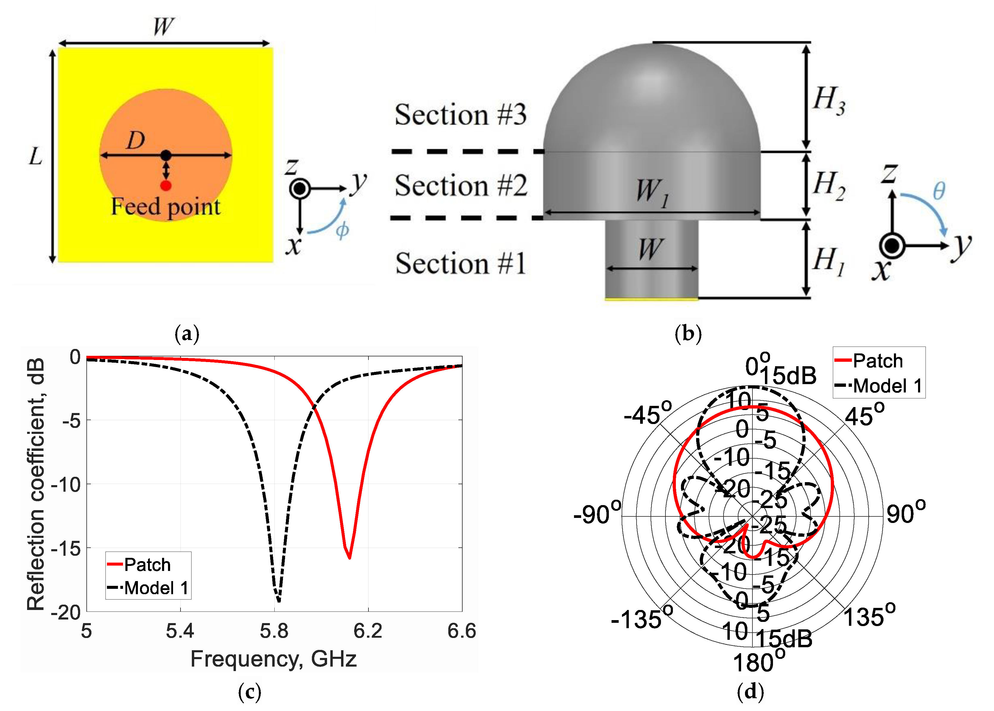
2.1. Reference Lens Antenna Design (Model 1)

Throughout the work in this paper, a microstrip circular patch antenna is used as a radiator. As a dielectric lens structure is to be mounted on top of the circular patch, the size of the patch is chosen in consideration of the dielectric constant of the lens. The diameter of the circular patch is 18.6 mm on top of the 30 mm × 30 mm ground. It is fed with a coaxial feeding, 3 mm away from the center, as shown in Figure 1a. RT/duroid 5880 ( ε r = 2.2) with a 0.79 mm thickness is used as a substrate. The simulated results of the stand-alone patch antenna without a lens are shown in Figure 1c,d with solid lines. The antenna resonates at 6.12 GHz, with a directivity of 7.73 dBi.
For the lens design, we choose a dielectric constant ( ε r ) of 2.5, the relative permittivity of resin commonly used for stereolithography apparatus (SLA) 3D printing. The high-resolution SLA 3D printing method provides a smoother and less porous surface, as it forms a structure by focusing an ultraviolet laser onto a vat of photopolymer resin, while fused deposition modeling (FDM) uses fine powder from many kinds of materials. Although resin might have a higher dielectric loss than ABS, we use resin to take advantage of its smoother and less porous surface printing characteristics. The designed reference lens is divided into three sections. The first and second sections are cylinders with widths and heights of 30 mm and 25 mm, and 70 mm and 22 mm, respectively. The third section is a hemisphere with a radius of 35 mm. The first section is designed to deliver waves consistently to the second section while providing a proper impedance matching characteristic, as shown in Figure 1c. The second section configures a larger width for beam focusing, and the third section transforms a spherical wave into a plane wave for a directive beam. Through this configuration, a mushroom-shaped lens is formed, and its total height is 82 mm, or 1.585 λ at 5.8 GHz. The ratio of the height to the diameter is 1.14, as a means of increasing the aperture efficiency of the lens [35]. The simulated results are plotted with dashed lines in Figure 1c,d. As shown in Figure 1c, the reference lens antenna operates at 5.8 GHz. The simulated radiation pattern at 5.8 GHz in the elevation plane (i.e., θ is swept when ϕ = 0 ° ) is shown in Figure 1d. The directivity of the reference dielectric lens antenna is 14.6 dBi, which is 6.9 dB higher than that of the circular patch antenna. The next step is to reduce the lens height while maintaining its radiation performance.

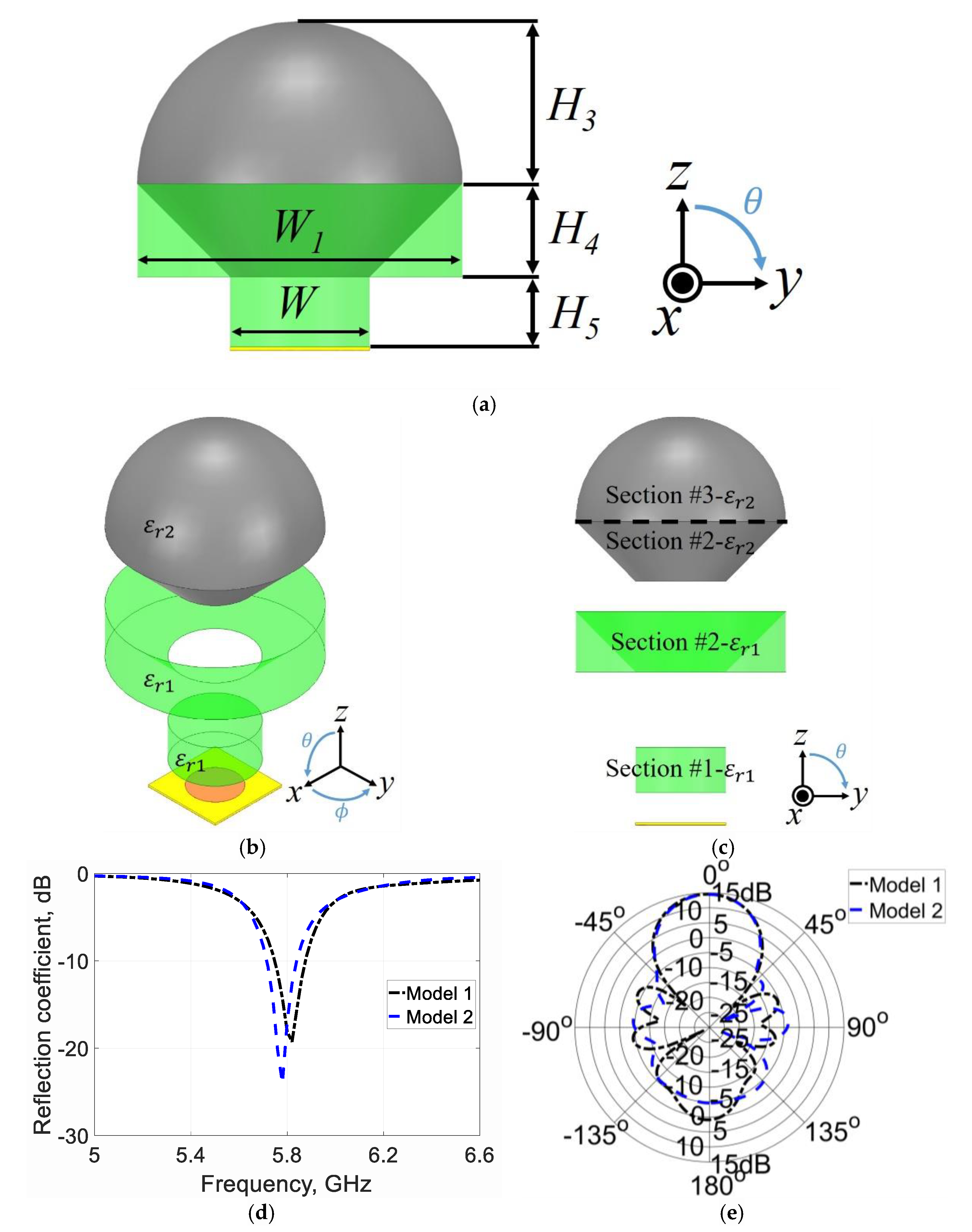
2.2. Reduction of Lens Height (Model 2)

Intensive studies have been carried out to lower the height of the lens [28,29]. In [28], the height was reduced without degrading the antenna performance through the air cavity in the radiator part while maintaining the thickness of the lens wall for structural stability. In [29], the lens height was reduced by setting the gap from the antenna source to the lens and the air slab by considering the phase velocity of the radiated waves passing through each area of the lens sections. In this work, we design the dielectric constant of the first cylinder (Section 1) in contact with the radiating patch, as shown in Figure 2c in light green, which is lower than 2.5, with
v p = 1 μ ε  ,
such that the phase velocity is increased. As the phase velocity increases, the height of the dielectric lens can be reduced because a wavefront can reach the same position even through a shorter path, or via a reduced height. Thus, the reduced height cylinder yields the same performance as the reference lens [36]. The skirt part, Section 2, marked in light green, is also farther from the excited patch than the gray part of Section 2, as shown in Figure 2c. Therefore, as shown in Figure 2b, when the dielectric constant of the skirt portion is lowered, the height of the lens can be reduced. The overall height of the lens can be reduced this way by assigning a lower dielectric constant of the lens sections, as they are farther away from the excitation [19,28,29]. We carry out parametric studies on the dielectric constant ( ε r 1 ) of the light green section of model 2. The dielectric constant of the other parts is fixed as ε r 2 = 2.5. The results are shown in Figure 3. As can be seen in Figure 3a, the resonant frequency is naturally shifted downward with a higher value of ε r 1 . The radiation pattern barely changes at the resonant frequency as shown by Figure 3b. However, as can be seen from Figure 3c, the front-to-back ratio is higher by 1 to 3 dB at each resonance when ε r 1 is 2. Therefore, the dielectric constant of the light green section in model 2 is chosen as 2, with an operating frequency of 5.8 GHz.
Using this design strategy, the final lens design of model 2 is H4 = 20 mm, H5 = 15 mm, and ε r 1 = 2, and ε r 2 = 2.5. The total height of the lens is reduced to 70 mm, 1.353 λ at the same resonance frequency of 5.8 GHz (see Figure 2d). The simulated radiation pattern is very similar to that of the reference design, as shown in Figure 2e. The directivity of model 2 is 14.5 dBi, which is about the same directivity of the reference lens antenna.

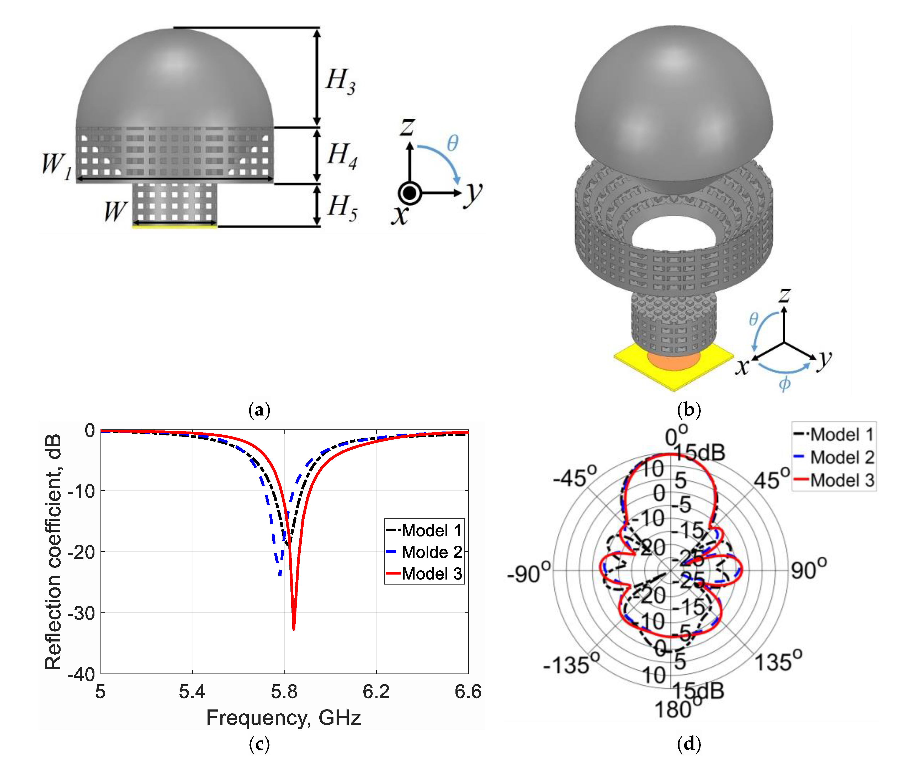
2.3. Reduced Height Lens Design with a Single 3D Printing Material (Model 3)

In this section, we show that different effective dielectric constant values from the same printing material can be achieved by perforating holes in the printed body and applying the technique to the lens design of model 2. Although the dielectric lens of model 2 shows a radiation performance close to the reference design of model 1 with a 15% reduced height, it consists of two dielectric constant values. If two other materials are used during actual production with a 3D printer, the fabrication complexity should increase, and the expected performance would change due to the non-negligible dielectric effect of an adhesive attaching the other printed bodies. The overall fabrication time must also increase.
We use a ring resonator method [37,38,39,40,41,42] when adjusting the dielectric constant of bulk printed material, as shown in Figure 4. When compared with the frequency response of a reference value of 2.5 (the dielectric constant of printed resin) for the dielectric cylinder (Figure 4a), the effective dielectric constant of a material made of the same material but with holes inside should change [37,43]. The dielectric constant of the material under test can be inferred in this way. From the black dash-dot line in Figure 4d, we can see that the ring resonator resonates at 5.6 GHz when the printed cylindrical resin with a dielectric constant of 2.5 is placed on top of the ring resonator. The cylinder is 30 mm in diameter and 15 mm in height, large enough to cover the ring resonator. We also see that the resonator resonates at 5.74 GHz (as shown in Figure 4, marked by a blue dashed line), when a cylinder with a dielectric constant of 2 in Figure 4b is placed. Based on this, a change in the resonant frequency can be checked when a perforated sample is placed on top of the ring resonator, as shown in Figure 4c. If its resonance frequency is found to be close to the sample dielectric constant of 2, it can be said that the structure is designed with an appropriate number of holes and size to have a dielectric constant close to 2. In Figure 4d,e, we conduct a parametric study on the transmission coefficient according to the size and number of the holes. The cubical hole dimension is depicted in Figure 4c. In Figure 4d, the transmission coefficients according to the hole size are given with the fixed number of holes of 208. It is clearly observed that the resonance of the transmission coefficient is shifted upward with a larger R of the holes, and it is closest to the reference when R is 2 mm. In Figure 4e, the transmission coefficient with the number of the holes is plotted, with R = 2 mm. We can see that the graph approaches the reference when the number of holes is 208. In other words, a larger hole will reduce the portion filled with resin and the effective dielectric constant will be reduced. By the same token, a smaller hole will bring the effective dielectric constant closer to 2.5. As shown by the red solid lines in Figure 4d,e, the resonant frequency is well matched with the case of bulk material with a dielectric constant of 2 (see the blue dashed line), when the cubical hole size is 2 × 2 × 2 [mm3] with a total number of 208 holes that are made down into the center of the cylinder.
Before applying the configuration of Figure 4c to the lens design, we verify the computed expectations as shown in Figure 4 experimentally. The cylindrical sample is printed with the SLA 3D printer Formlabs Inc., Form 3, as shown in the photos in Figure 5a. The material properties are measured using the dielectric constant and loss tangent measurement system from KEYCOM [44]. As shown in Figure 5b, the measured material properties are found to be ε r = 2.32 and t a n δ = 0.0804 for the reference, and ε r = 2.15 and t a n δ = 0.0686 for the proposed perforated block. Both are measured at 5.8 GHz. They deviated slightly from the simulation setup of 2.5 but are within the acceptable measurement error range.
The part with a dielectric constant of 2 in the model 2 lens design can be replaced by this configuration, made of a single resin ( ε r = 2.5). While maintaining the size of the model 2 lens design, we replace sections #1 and #2 in Figure 2b,c with perforated structures, as shown in Figure 6a,b. Note again that all the to-be-printed blocks of the lens in the proposed design in Figure 6 require only the same material as the resin. This enables the 3D printing process to be carried out using a single material, and the effectiveness of 3D printing technology for lens design can be maximized through one-take printing. The electrical properties of the lens antennas, including the reference, model 2, and the proposed model 3, are compared in Figure 6 and Figure 7. As shown in Figure 6c,d, the three designs of the lens antenna operate at the same target frequency and show very similar radiation patterns. The directivity of the proposed lens antenna model 3 is 14.6 dBi, and its simulated gain is 9.82 dBi with a radiation efficiency of 31%. The low radiation efficiency is mainly due to the poor loss characteristic of the resin used. However, the gain is still acceptable compared to the electrical size of the lens, as shall be seen from Table 1. The operating bandwidth is 2.4% with a –10 dB criterion. Figure 7 shows the electric field distribution at 5.8 GHz, and Figure 8 shows Poynting’s vector distribution at 5.8 GHz. In Figure 7a and Figure 8a, for the reference design, the radiated spherical wave is manipulated into the plane wave by the lens structure. Consequently, we see that such a transformation is observed in the reduced propagation path in Figure 7b and Figure 8b for model 2, and a similar distribution is observed in Figure 7c and Figure 8c for model 3. Thus, it is proved that a similar radiation performance can be maintained at the reduced lens height, and such reduced height can be realized using a single printing material.

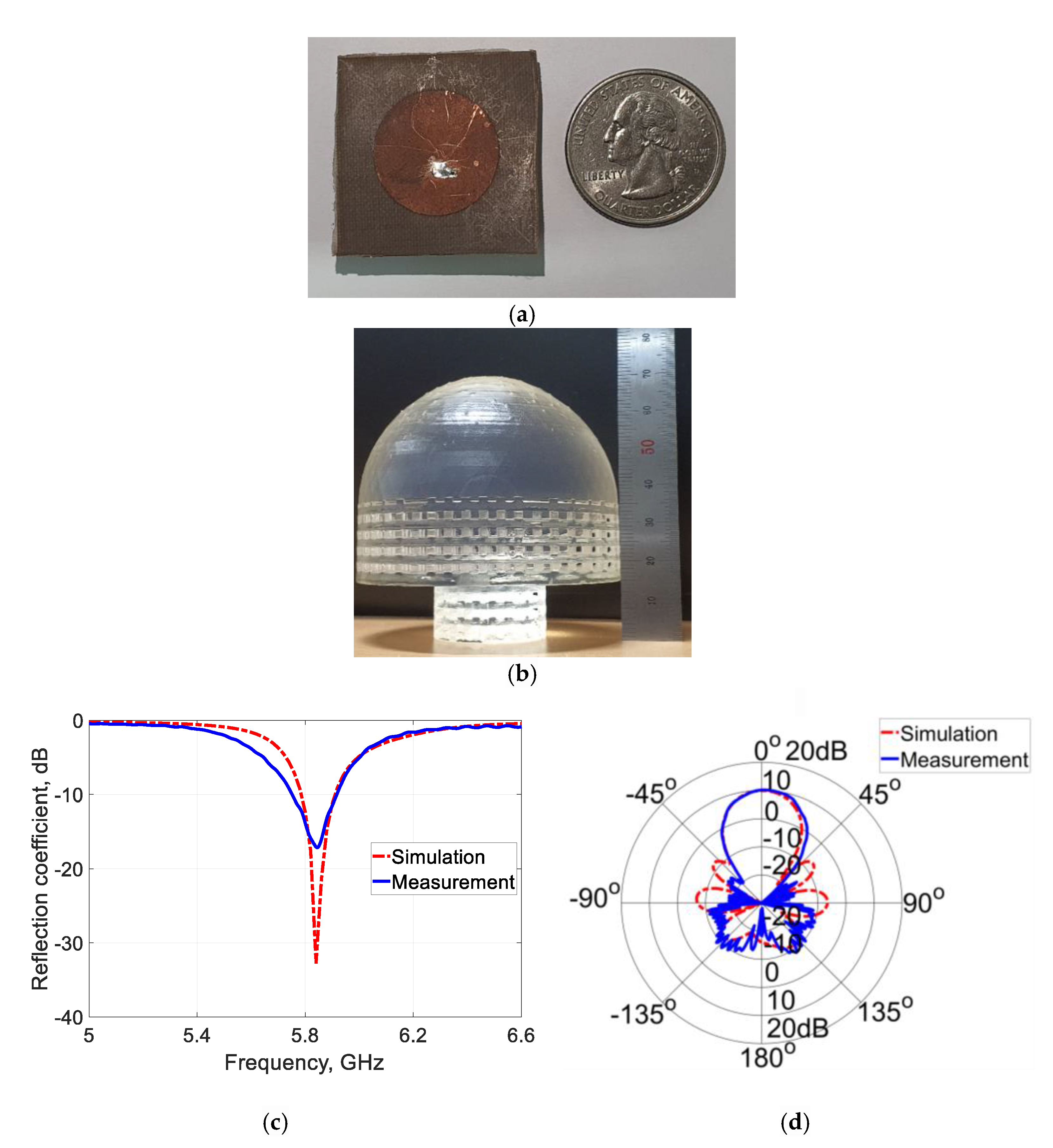
3. Experimental Validation

The microstrip circular patch antenna is manufactured using a conventional etching process on the Rogers RT/duroid 5880 substrate ( ε r   = 2.2), with a thickness of 0.79 mm, as shown in Figure 9a. The proposed lens is printed using Form 3 from Formlabs Inc., with the resin material RL-F2-GPCL-04 and the printing resolution of 100 μ m. Its photo is shown in Figure 9b. The reflection coefficient is measured with the Anritsu MS46522B, and its impedance is matched from 5.75 GHz to 5.92 GHz with the –10 dB criterion, as shown in Figure 9c. The measured value is slightly broader, meaning that the built prototype is slightly lossy compared to the computed expectation. A little higher loss could occur from the printed lens and the fabrication tolerance that the lens and the patch are not perfectly attached. Nevertheless, the measurement agrees sufficiently with the simulation. Figure 9d shows the simulated and measured radiation patterns in the elevation plane. The radiation pattern is measured in an anechoic chamber, and it agrees well with the simulation. The measured gain of the proposed lens antenna is 10.12 dBi, which is very close to the simulated value of 9.82 dBi. Therefore, we prove that resin can be used for a 3D printed lens design, and furthermore, it can be used even more efficiently with one-take 3D printing when a proper modification is implemented.
Lastly, in Table 1, the performance of the proposed lens is compared with previously reported lens antenna designs in terms of the dimension and measured gain. We set a figure-of-merit (FOM) to be a gain value over the largest electrical dimension of the lens. The proposed design occupies the smallest dimension with an acceptable level of the FOM. Note that the 3DP lenses in the table are all made via a one-take 3D printing process.

4. Conclusions

In this paper, we showed that one-take 3D printing is available for a resin-based lens antenna design while achieving a reduced lens height. The directivity of the final lens antenna design increased by 6.87 dB compared to the conventional microstrip circular patch antenna. When compared with the reference lens antenna, the height was reduced by 15%. The lens height was first reduced by a combination of sections of different dielectric materials; then, this reduction becomes available with proper perforation of the dielectric lens with a single material that can be printed with one-take 3D SLA printing. During the modification of the lens with perforations, the effective dielectric constant was identified with ring resonator response simulations. The dielectric properties of the proposed lens configuration were experimentally checked with a dielectric constant measurement system.
The working mechanism of the lens was analyzed and explained using full-wave EM simulations. A prototype was built, and all computed expectations were verified experimentally. Although the loss of the resin material might be higher than that of other 3DP ABS filaments, resin can be more efficiently used at higher frequencies, as it can provide a smoother and less porous printout. This work has proved that permittivity values can be adjusted with structure shaping, and such a technique is expected to be useful in 3DP antenna designs.

Author Contributions

Conceptualization, W.K. and I.-J.Y.; Methodology, W.K., J.K. and I.-J.Y.; Software, W.K., J.K. and I.-J.Y.; Validation, W.K., J.W. and I.-J.Y.; Formal Analysis, W.K., J.K., J.W. and I.-J.Y.; Investigation, W.K., J.K. and I.-J.Y.; Resources, W.K., J.K., J.W., D.Y. and I.-J.Y.; Data Curation, W.K., J.K. and I.-J.Y.; Writing—Original Draft Preparation, W.K.; Writing—Review and Editing, I.-J.Y.; Visualization, W.K.; Supervision, I.-J.Y. All authors have read and agreed to the published version of the manuscript.

Funding

This work was supported by Korea Research Institute for Defense Technology Planning and Advancement (KRIT)-Grant funded by Defense Acquisition Program Administration (DAPA, Korea) (KRIT-CT-21-038).

Institutional Review Board Statement

Not applicable.

Informed Consent Statement

Not applicable.

Data Availability Statement

Not applicable.

Conflicts of Interest

The authors declare no conflict of interest.

References

  1. Sage, G.P.L. 3D printed waveguide slot array antennas. IEEE Access 2016, 4, 1258–1265. [Google Scholar] [CrossRef]
  2. Tak, J.; Kantemur, A.; Sharma, Y.; Xin, H. A 3-D-Printed W-Band Slotted Waveguide Array Antenna Optimized Using Machine Learning. IEEE Antennas Wirel. Propag. Lett. 2018, 17, 2008–2012. [Google Scholar] [CrossRef]
  3. Honari, M.M.; Mirzavand, R.; Saghlatoon, H.; Mousavi, P. Investigation of the 3D Printing Roughness Effect on the Performance of a Dielectric Rod Antenna. IEEE Antennas Wirel. Propag. Lett. 2018, 17, 2075–2079. [Google Scholar] [CrossRef]
  4. Huang, G.-L.; Zhou, S.-G.; Sim, C.-Y.; Chio, T.-H.; Yuan, T. Lightweight Perforated Waveguide Structure Realized by 3-D Printing for RF Applications. IEEE Trans. Antennas Propag. 2017, 65, 3897–3904. [Google Scholar] [CrossRef]
  5. Radha, S.M.; Shin, G.; Park, P.; Yoon, I.-J. Realization of Electrically Small, Low-Profile Quasi-Isotropic Antenna Using 3D Printing Technology. IEEE Access 2020, 8, 27067–27073. [Google Scholar] [CrossRef]
  6. Dionigi, M.; Tomassoni, C.; Venanzoni, G.; Sorrentino, R. Simple high-performance metal-plating procedure for stereolithographically 3-D-printed waveguide components. IEEE Microw. Wirel. Compon. Lett. 2017, 27, 953–955. [Google Scholar] [CrossRef]
  7. Alkaraki, S.; Andy, A.S.; Gao, Y.; Tong, K.-F.; Ying, Z.; Donnan, R.; Parini, C. Compact and Low-Cost 3-D Printed Antennas Metalized Using Spray-Coating Technology for 5G mm-Wave Communication Systems. IEEE Antennas Wirel. Propag. Lett. 2018, 17, 2051–2055. [Google Scholar] [CrossRef]
  8. Borda-Fortuny, C.; Cai, L.; Tong, K.F.; Wong, K.-K. Low-Cost 3D-Printed Coupling-Fed Frequency Agile Fluidic Monopole Antenna System. IEEE Access 2019, 7, 95058–95064. [Google Scholar] [CrossRef]
  9. Saghlatoon, H.; Boroujeni, R.M.; Honari, M.M.; Mousavi, P. Low-cost inkjet printed passive booster for increasing the magnetic coupling in proximity of metal object for NFC systems. IEEE Microw. Wirel. Compon. Lett. 2016, 26, 996–998. [Google Scholar] [CrossRef]
  10. Lou, Y.-H.; Zhu, Y.-X.; Fan, G.-F.; Lei, W.; Lu, W.-Z.; Wang, X.-C. Design of Ku-band flat Luneburg lens using ceramic 3-D printing. IEEE Antennas Wirel. Propag. Lett. 2020, 20, 234–238. [Google Scholar] [CrossRef]
  11. Mirmozafari, M.; Saeedi, S.; Saeidi-Manesh, H.; Zhang, G.; Sigmarsson, H.H. Direct 3-D printing of nonplanar linear-dipole-phased array antennas. IEEE Antennas Wirel. Propag. Lett. 2018, 17, 2137–2140. [Google Scholar] [CrossRef]
  12. Pizarro, F.; Salazar, R.; Rajo-Iglesias, E.; Rodriguez, M.; Fingerhuth, S.; Hermosilla, G. Parametric Study of 3D Additive Printing Parameters Using Conductive Filaments on Microwave Topologies. IEEE Access 2019, 7, 106814–106823. [Google Scholar] [CrossRef]
  13. Brown, E.R.; Abdalmalak, K.A.; Zhang, W. Effect of Metal Resistive Losses on the Gain of a THz Planar Spiral Antenna. In Proceedings of the 2020 14th European Conference on Antennas and Propagation (EuCAP), Copenhagen, Denmark, 15–20 March 2020; pp. 1–4. [Google Scholar]
  14. Park, J.S.; Hong, J.H.; Kim, K.W. Design of 24–40 GHz ultra-wideband circularly polarized monopole antenna with a defected ground plane. J. Electromagn. Eng. Sci. 2022, 22, 379–385. [Google Scholar] [CrossRef]
  15. Nam, S.; Choi, S.; Ryu, J.; Lee, J. Compact 28 GHz folded Butler matrix using low-temperature co-fired ceramics. J. Electromagn. Eng. Sci. 2022, 22, 452–458. [Google Scholar] [CrossRef]
  16. Kamal, S.; Bin Ain, M.F.; Ullah, U.; Mohammed, A.S.B.; Hussin, R.; Omar, M.F.B.M.; Najmi, F.; Ahmad, Z.A.; Ab Rahman, M.F.; Mahmud, M.N.; et al. A Low-Profile Quasi-Loop Magneto-Electric Dipole Antenna Featuring a Wide Bandwidth and Circular Polarization for 5G mmWave Device-to-Device Communication. J. Electromagn. Eng. Sci. 2022, 22, 459–471. [Google Scholar] [CrossRef]
  17. Geterud, E.G.; Bergmark, P.; Yang, J. Lightweight waveguide and antenna components using plating on plastics. In Proceedings of the 2013 7th European Conference on Antennas and Propagation (EuCAP), Gothenburg, Sweden, 8–12 April 2013; pp. 1812–1815. [Google Scholar]
  18. Ghassemiparvin, B.; Ghalichechian, N. Design, fabrication, and testing of a helical antenna using 3D printing technology. Microw. Opt. Technol. Lett. 2020, 62, 1577–1580. [Google Scholar] [CrossRef]
  19. Jo, E.-S.; Kim, D. 3-D printer based lens design method for integrated lens antennas. IEEE Antennas Wirel. Propag. Lett. 2018, 17, 2090–2093. [Google Scholar] [CrossRef]
  20. Cai, Z.; Zhou, Y.; Weng, Z.; Deng, L.; Luo, Y.; Yu, M.; Qi, Y. 3-D printing conformal K-band lens antenna for a smart parking space detection system. IEEE Trans. Instrum. Meas. 2020, 69, 8514–8525. [Google Scholar] [CrossRef]
  21. Wang, C.; Wu, J.; Guo, Y.-X. A 3-D-printed wideband circularly polarized parallel-plate Luneburg lens antenna. IEEE Trans. Antennas Propag. 2020, 68, 4944–4949. [Google Scholar] [CrossRef]
  22. Wu, G.B.; Zeng, Y.-S.; Chan, K.F.; Qu, S.-W.; Chan, C.H. High-Gain Circularly Polarized Lens Antenna for Terahertz Applications. IEEE Antennas Wirel. Propag. Lett. 2019, 18, 921–925. [Google Scholar] [CrossRef]
  23. Belen, A.; Güneş, F.; Mahouti, P.; Palandöken, M. A novel design of high performance multilayered cylindrical dielectric lens antenna using 3D printing technology. Int. J. RF Microw. Comput. Eng. 2019, 30, e21988. [Google Scholar] [CrossRef]
  24. Konstantinidis, K.; Feresidis, A.P.; Constantinou, C.C.; Hoare, E.; Gashinova, M.; Lancaster, M.J.; Gardner, P. Low-THz dielectric lens antenna with integrated waveguide feed. IEEE Trans. THz Sci. Technol. 2017, 7, 572–581. [Google Scholar] [CrossRef] [Green Version]
  25. Mahouti, P.; Belen, M.A.; Güneş, F.; Yurt, R. Design and realization of multilayered cylindrical dielectric lens antenna using 3D printing technology. Microw. Opt. Technol. Lett. 2019, 61, 1400–1403. [Google Scholar] [CrossRef]
  26. Giddens, H.; Hao, Y. Multibeam Graded Dielectric Lens Antenna from Multimaterial 3-D Printing. IEEE Trans. Antennas Propag. 2020, 68, 6832–6837. [Google Scholar] [CrossRef]
  27. Zhang, Y.-X.; Jiao, Y.-C.; Liu, S.-B. 3-D-Printed Comb Mushroom-Like Dielectric Lens for Stable Gain Enhancement of Printed Log-Periodic Dipole Array. IEEE Antennas Wirel. Propag. Lett. 2018, 17, 2099–2103. [Google Scholar] [CrossRef]
  28. Nguyen, N.T.; Rolland, A.; Boriskin, A.V.; Valerio, G.; Le Coq, L.; Sauleau, R. Size and Weight Reduction of Integrated Lens Antennas Using a Cylindrical Air Cavity. IEEE Trans. Antennas Propag. 2012, 60, 5993–5998. [Google Scholar] [CrossRef]
  29. Wang, K.X.; Wong, H. Design of a wideband circularly polarized millimeter-wave antenna with an extended hemispherical lens. IEEE Trans. Antennas Propag. 2018, 66, 4303–4308. [Google Scholar] [CrossRef]
  30. Malik, B.T.; Doychinov, V.; Zaidi, S.A.R.; Robertson, I.D.; Somjit, N. Antenna Gain Enhancement by Using Low-Infill 3D-Printed Dielectric Lens Antennas. IEEE Access 2019, 7, 102467–102476. [Google Scholar] [CrossRef]
  31. Mall, L.; Waterhouse, R. Millimeter-wave proximity-coupled microstrip antenna on an extended hemispherical dielectric lens. IEEE Trans. Antennas Propag. 2001, 49, 1769–1772. [Google Scholar] [CrossRef]
  32. Artemenko, A.; Mozharovskiy, A.; Maltsev, A.; Maslennikov, R.; Sevastyanov, A.; Sorin, V. 2D electronically beam steerable integrated lens antennas for mmWave applications. In Proceedings of the 2012 42nd European Microwave Conference, Amsterdam, Netherlands, 29 October–1 November 2012; pp. 213–216. [Google Scholar]
  33. Costa, J.R.; Lima, E.B.; Fernandes, C.A. Compact beam-steerable lens antenna for 60-GHz wireless communications. IEEE Trans. Antennas Propag. 2009, 57, 2926–2933. [Google Scholar] [CrossRef]
  34. García-Muñoz, E.; Abdalmalak, K.A.; Santamaría, G.; Rivera-Lavado, A.; Segovia-Vargas, D.; Castillo-Araníbar, P.; Van Dijk, F.; Nagatsuma, T.; Brown, E.R.; Guzman, R.C.; et al. Photonic-based integrated sources and antenna arrays for broadband wireless links in terahertz communications. Semicond. Sci. Technol. 2019, 34, 054001. [Google Scholar] [CrossRef]
  35. Karki, S.K.; Ala-Laurinaho, J.; Viikari, V. Integrated metal-lens antennas with reduced height at 71–76 GHz. In Proceedings of the 2019 13th European Conference on Antennas and Propagation (EuCAP), Krakow, Poland, 31 March–5 April 2019; pp. 1–5. [Google Scholar]
  36. Balanis, C.A. Advanced Engineering Electromagnetics, 2nd ed.; Wiley: Hoboken, NJ, USA, 2012. [Google Scholar]
  37. Moscato, S.; Bahr, R.; Le, T.; Pasian, M.; Bozzi, M.; Perregrini, L.; Tentzeris, M.M. Infill-dependent 3-D-printed material based on NinjaFlex filament for antenna applications. IEEE Antennas Wirel. Propag. Lett. 2016, 15, 1506–1509. [Google Scholar] [CrossRef]
  38. Waldron, I.; Makarov, S.; Biederman, S.; Ludwig, R. Suspended Ring Resonator for Dielectric Constant Measurement of Foams. IEEE Microw. Wirel. Compon. Lett. 2006, 16, 496–498. [Google Scholar] [CrossRef]
  39. Sarabandi, K.; Li, E. Microstrip ring resonator for soil moisture measurements. IEEE Trans. Geosci. Remote. Sens. 1997, 35, 1223–1231. [Google Scholar] [CrossRef] [Green Version]
  40. Bernard, P.A.; Gautray, J.M. Measurement of dielectric constant using a microstrip ring resonator. IEEE Trans. Microw. Theory Tech. 1991, 39, 592–595. [Google Scholar] [CrossRef]
  41. Alahnomi, R.A.; Zakaria, Z.; Ruslan, E.; Rashid, S.R.A.; Bahar, A.A.M. High-Q sensor based on symmetrical split ring resonator with spurlines for solids material detection. IEEE Sens. J. 2017, 17, 2766–2775. [Google Scholar] [CrossRef]
  42. Jang, S.-Y.; Yang, J.-R. Double split-ring resonator for dielectric constant measurement of solids and liquids. J. Electromagn. Eng. Sci. 2022, 22, 122–128. [Google Scholar] [CrossRef]
  43. Zhang, S.; Arya, R.K.; Pandey, S.; Vardaxoglou, Y.; Whittow, W.; Mittra, R. 3D-printed planar graded index lenses. IET Microw. Antennas Propag. 2016, 10, 1411–1419. [Google Scholar] [CrossRef] [Green Version]
  44. Shin, G.; Kim, W.; Kim, M.C.; Kim, J.; Chung, J.-Y.; Nah, J.; Yoon, I.-J. A deionized water infilled dual-layer insulator applied brain-implanted UWB antenna for wireless biotelemetry applications. IEEE Trans. Antennas Propag. 2022, 70, 6469–6478. [Google Scholar] [CrossRef]
Figure 1. Reference lens antenna simulation. (a) Reference patch antenna. (b) Reference lens antenna (model 1). (c) Reflection coefficient. (d) θ -sweep radiation pattern ( ϕ = 0 ° ). The design parameters are W = 30, L = 30, D = 18.6, W1 = 70, H1 = 25, H2 = 22, and H3 = 35. All units are in millimeters.
Applsci 12 11811 g001
Figure 2. Dielectric lens antenna (model 2) simulation. (a) Simulation model. (b) Perspective view of the lens (disintegrated). (c) Side view of the lens (disintegrated). (d) Reflection coefficient. (e) θ -sweep radiation pattern ( ϕ = 0 ° ). The design parameters are H4 = 20, and H5 = 15. All units are in millimeters.
Applsci 12 11811 g002
Figure 3. Parametric study of the dielectric constant ( ε r 1 ) of the light green section. (a) Reflection coefficient. (b) θ -sweep radiation pattern ( ϕ = 0 ° ). (c) Front-to-back ratio.
Applsci 12 11811 g003
Figure 4. Ring resonator simulation. (a) Setup with a sample of ε r = 2.5. (b) Setup with a sample of ε r = 2. (c) Setup with a sample of ε r = 2.5 with holes. (d) Transmission coefficient according to R. (e) Transmission coefficient according to the number of holes.
Applsci 12 11811 g004
Figure 5. Dielectric properties of the printed resin. (a) Printed reference and perforated cylinders with resin material. (b) Measured dielectric properties of the samples.
Applsci 12 11811 g005
Figure 6. Proposed design (model 3). (a) Simulation model. (b) Perspective view of the proposed design. (c) Reflection coefficient. (d) θ -sweep radiation pattern ( ϕ = 0 ° ).
Applsci 12 11811 g006
Figure 7. E-field distribution at 5.8 GHz. (a) Model 1. (b) Model 2. (c) Model 3.
Applsci 12 11811 g007
Figure 8. Poynting’s vector plot at 5.8 GHz. (a) Model 1. (b) Model 2. (c) Model 3.
Applsci 12 11811 g008
Figure 9. Fabrication of the proposed lens antenna. (a) Microstrip patch antenna. (b) Proposed dielectric lens antenna. (c) Reflection coefficient. (d) θ -sweep radiation pattern ( ϕ = 0 ° ).
Applsci 12 11811 g009
Table 1. Comparison table of the lens antenna. All the values are from the measurement. The wavelength for the dimension is calculated at the center frequency.
ReferenceOperating Frequency [GHz]Largest Dimension [ λ ] Gain [dBi]FOM
[19]5.4–8.21.812.16.72
[25]8–12212.586.29
[27]14–202.7111.24.13
[30]26.6–29.4315.65.2
27.6–291.512.18.07
This work5.81.410.127.23
Publisher’s Note: MDPI stays neutral with regard to jurisdictional claims in published maps and institutional affiliations.

