
Prediction of Ply Angles of Air Springs According to Airbag Positions and Their Effects on Lateral and Torsional Stiffness

1
Department of Automotive Engineering, Korea National University of Transportation, Chungju 27469, Republic of Korea
2
Department of Railway Vehicle System Engineering, Korea National University of Transportation, Uiwang 16106, Republic of Korea
*
Author to whom correspondence should be addressed.
Appl. Sci. 2022, 12(22), 11815; https://0-doi-org.brum.beds.ac.uk/10.3390/app122211815
Submission received: 12 October 2022
/
Revised: 2 November 2022
/
Accepted: 18 November 2022
/
Published: 21 November 2022
(This article belongs to the Special Issue Innovative Design and Manufacturing Processes for Engineering Materials)
Abstract
:Featured Application
Diaphragm-type air springs in railway vehicles.
Abstract
The stiffness in various directions of air springs have a great influence on the stability of high-speed trains. Due to the change in the bogie structure, the required functions of the air springs have also diversified, and the damping of various loading modes such as vertical, lateral, and torsional movements is emerging as important. The stiffnesses are affected by the shape of the air bag, the material, and the ply angles. In this paper, the relationship between the ply angle and the radial position is proposed by equations from deformation modes. The variable angles in the plies were compared and demonstrated in air-spring analysis using the rebar elements. The vertical, lateral, and torsional stiffness of air springs without auxiliary springs were compared between constant ply angles and variable ply angles with respect to the positions. When mainly dealing with the vertical stiffness, the effect of the angle variation was small; however, it was found that it had a large effect of more than 24% and 30% on the stiffness in the lateral direction and torsional direction, respectively.
1. Introduction
Air springs are composed of an air bag, steel beads, a bead ring plate, an upper plate, a lower plate, and a rubber spring as the auxiliary spring. The air bag is made of multi-layered, reinforced fiber, rubber laminated matrix ply, inner and outer rubber shells. For railways, the diaphragm type in the form of a round tire is mainly used, and for buses and passenger cars, the rolling lobe type in the form of a sleeve is mainly used. Air springs have a low natural frequency, which could minimize transmission of vibration. Air springs can also change the spring stiffness by adjusting the air volume and internal pressure.
Research has been conducted to predict the stiffness of air springs using theoretical models because the stiffness of the air spring is the most important among various specifications. It is mainly affected by the shape and cord angles of the bag, but the properties of the composite material are not considered in theory. Xu [1] constructed a vertical stiffness analytical model of a rolling lobe air-spring based on hydrodynamics and thermodynamics and verified by comparing with the experimental data. The influence of the geometrical parameters such as diaphragm volume, auxiliary chamber volume, and the shape coefficient were analyzed and discussed. Li et al. [2] established an analytical formula to predict the vertical stiffness of rolling lobe spring and verified by comparisons to an axisymmetric finite element simulations and experimental data. Precise prediction of the vertical stiffness was obtained using the formula in cases where the reservoir volume was relatively small. Qi et al. [3] constructed a model covering both the vertical and horizontal directions. In the vertical direction, they obtained the air spring’s reaction force by using the derivation of the pneumatics equations. In the horizontal direction, they used a quadratic function to fit the trends of the variation in the air spring’s horizontal stiffness, which was simulated by the finite element method.
Since the cord angle affects the spring constant, it has been used as a variable in the study of stiffness. Lu et al. [4] studied the aging mechanism of air springs. They analyzed the effect of aging on the vertical static stiffness of an air spring through an accelerated aging test and finite element simulation. They also examined the vertical static stiffness of air springs with different cord angles and the existence of emergency auxiliary spring during aging. It was found that the vertical stiffness increases with aging, as the cord angle is small, and there is no auxiliary spring. Lee and Huh [5] investigated the effect of design variables with the variation of the cord angle of an air bag. The orthotropic material and axisymmetric model were adopted. It was revealed that an air bag had different modes of deformation according to the cord angle and had different modes of change in the outer diameter and the fold height with deformation. Lee and Huh [6] also developed finite element code considering the orthotropic material properties and degenerated shell element to analyze a diaphragm-type air spring. They simulated the inflation and lateral deflection with a half symmetric model.
In the analysis of air springs, angles are often modeled and analyzed as one value; thus, it is difficult to accurately input the angle and thickness due to the complex shape in which the values vary at all points along the latitude. The analysis of the fiber reinforced to support the load in the rubber base material is often used by the rebar element in the ABAQUS software. If the rebar element is used, the angle of the cord can be input differently for each element, and the change of the angle can also be tracked. Toyokawa et al. [7] developed a simulation technology that accurately predicts the static and dynamic characteristics of air springs. To verify the validity of the angular distribution of reinforcing fibers predicted by simulation, they carried out a nondestructive investigation of the angular distribution using an X-ray CT. Sarıoğlu and Durmuş [8] explained the method of manufacturing and testing of air springs. They developed the elastomer materials, the necessary machinery, and the equipment for producing and testing air springs. Wenku et al. [9] carried out a finite element analysis model of a sleeve-type air spring with the software ABAQUS to study the influence of cord-fabric layer parameters on the elastic characteristics of air springs. They revealed that the cord angle and cord interval had a relatively greater effect on the elastic characteristics of air springs. Lee et al. [10] conducted an air-spring simulation model with rebar elements as fibers in the plies including the mounting steps of the air bag. They traced the changing history of the ply angles of inner and outer plies during the full analysis. The results indicated that the ply angles of fibers varied from 38 degrees to 56 degrees during static loading. Weiser et al. [11] conducted a finite element model of an elastomer matrix with inserted cord to compare the stress and behavior at the interface between the fiber and the base material through experiments and finite element analysis.
The manufacturing process of a diaphragm-type air spring in which the upper and lower beads have a different radius is more complicated than the sleeve type in which the upper and lower beads have similar radius. The initial cord angle of the plies is changed in the airbag because the bag is inflated through the vulcanization operation in the manufacturing process. To accurately assign the angle of the ply to the airbag, different angles must be entered for each position along the bag’s latitudinal direction. In the case of sleeve-type airbags with similar radial lengths, assigning the angles is easy and a fiber angle tracing is also possible during deformation if the angle is given at the initial stage and the mounting process is analyzed [9,10]. In the case of a diaphragm-type air spring, the angle is different for each position along the latitudinal direction due to the rounded tube shape.
As a result of the literature surveys, there was no case of evaluating the stiffness in the lateral and torsional directions by considering both angle changes by position and tracking the angle during analysis in the diaphragm-type air spring. There was also no case of evaluating how the initial angle, which was not constant for each location, affected the stiffness. Some studies were established with the cord angle constant because it was difficult to predict and set up the angle according to the position of the airbag when predicting and evaluating the stiffness of the diaphragm-type air spring. In addition, the influence of the angle of the cord was small because the previous studies mainly focused on the prediction of the vertical stiffness.
In this study, the relationship between the ply angle and the radial position is proposed by measuring and converting the angle of the manufactured product. To model the fiber, the angle is set in the air spring using the rebar element in ABAQUS, and the change of the angle is predicted and verified during analysis. Based on the proposed equation, the angle in the initial airbag was calculated and set up, and the model of the constant angle and the model of the variable angle were analyzed. The effects were compared on vertical, lateral, and torsional stiffness through air spring analysis at an internal pressure of 6 bar. In addition, the method of applying the angle for each position to the ABAQUS input file is presented together.
2. Ply Angle Prediction
The 684N model, a diaphragm type used in the past with the K-TGV high-speed train, consisted of a rubber composite material reinforced with six layers of nylon fiber and inner and outer rubber. The ply angle was measured at seven points from the bead part of the upper plate (A) to the bead part of the lower plate (G), as shown in Figure 1 [5]. Airbags have a total of three pairs of equally angled plies, and the ply angles are opposite in the neighboring plies. The ply angle starts at point A and gradually increases until it passes the outermost points C and D, and the ply angle gradually decreases as it goes to the inner points E, F, and G.
The author presented a calculation equation for the ply angle in an airbag using the radius and initial angle in the reference [6] in 2001 as Equation (1). In this paper, an equation for calculating the angle was additionally proposed and verified. Since the airbag has an axisymmetric shape, a change in the radial position means a change in length in the circumferential direction. When the airbag length in the circumferential direction is increased by being pressurized or inflated, the thickness of the airbag reduces and the length in the latitudinal direction increases.
As shown in Figure 2, in a rectangle with the length in the same circumferential direction as the base and the length in the same longitudinal direction as the height, as the radius increases, the base increases. Regarding the change in thickness and height, in the first case, only the thickness changes and the height remains the same, and in the second case, there is no change in the thickness and the surface area of the airbag is the same before and after the deformation. Finally, the third case is a case in which the height and thickness are changed in proportion to the Poisson’s ratio due to the change in length in the circumferential direction. In each case, when the initial angle is and the initial radial position is , the angle at the final position can be expressed as , and can be expressed by Equations (1)–(3).
Figure 3 is a graph showing the change in ply angle at each position when changing from the radial position 137 to 340 mm after setting the ply angle of 11 degrees at the initial radius of 267 mm for the airbag model in Figure 4. Using the exponent of in Equations (1) and (2), Equation (1) and (2) are denoted as Angle_1st and Angle_2nd in Figure 3, respectively. Equation (3) is expressed as Angle_poisson. Equation (3) with the Poisson’s ratio set to 0.3 and 0.5 are located between Equations (1) and (2). As the Poisson’s ratio increases, Equation (3) moves from Equation (1) to Equation (2). Considering the change in thickness, Equations (1) and (2) represent the minimum and maximum ranges of the angle change of the airbag surface.
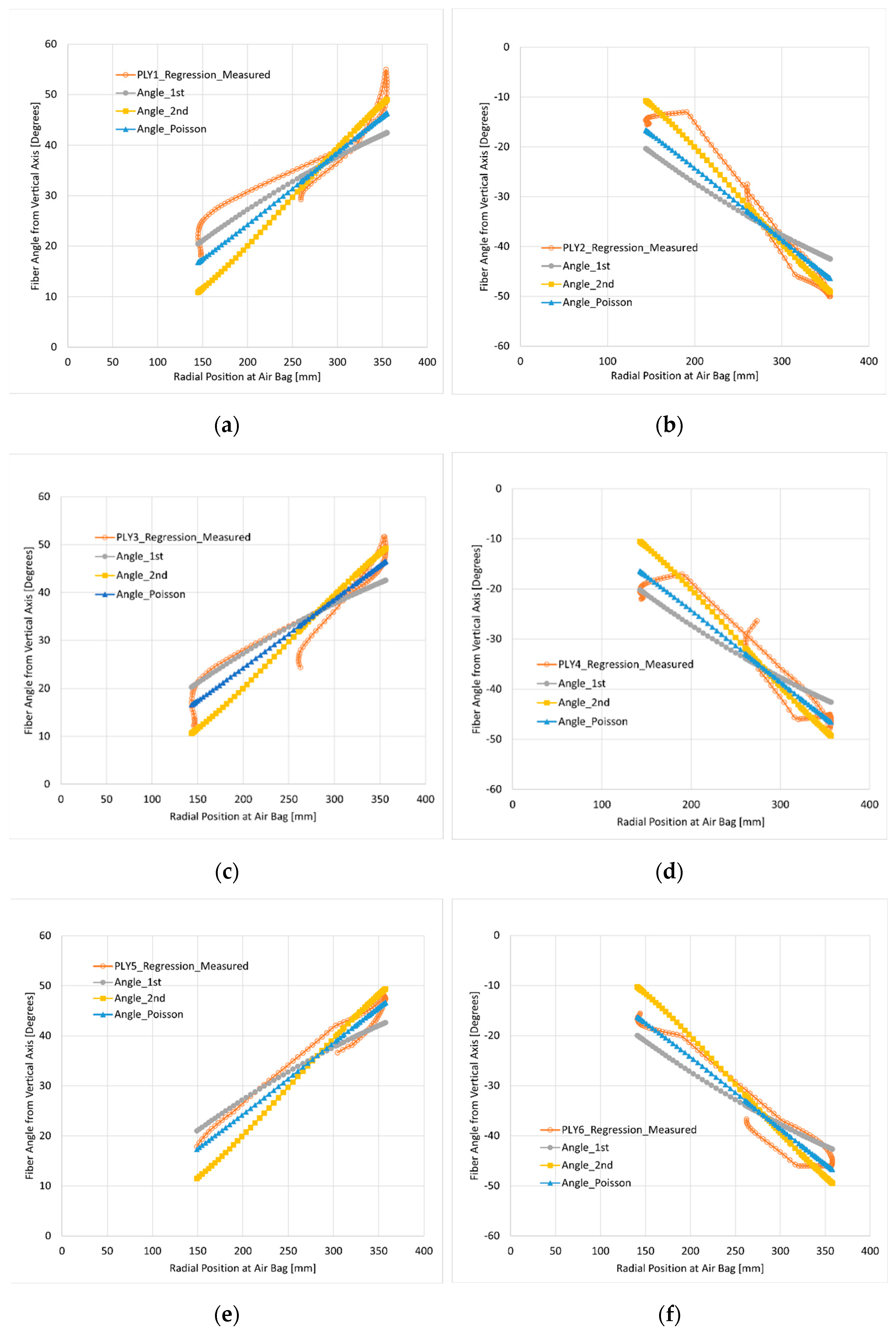
The angle distribution according to the longitudinal position from the upper plate to the lower plate of the airbag in Figure 1 is shown in Figure 5 for each ply by radial position and ply angles based on the shape of the 684N air spring. Figure 5 shows the angle calculated by setting the upper bead’s radial position of 282 mm and the initial angle of 36 degrees in the angle calculation equations. As a result of comparing the three angle calculation formulas for each ply, all three proposed equations are in good agreement with the measured data. It was found that the first ply fits Poisson’s Equation (3) well with Poisson’s ratio of 0.49, the second, the fourth, and the sixth plies fit Equation (2) well, and the third and the fifth plies fit Equation (1) well. Therefore, the proposed equations are valid.
3. Numerical Verification
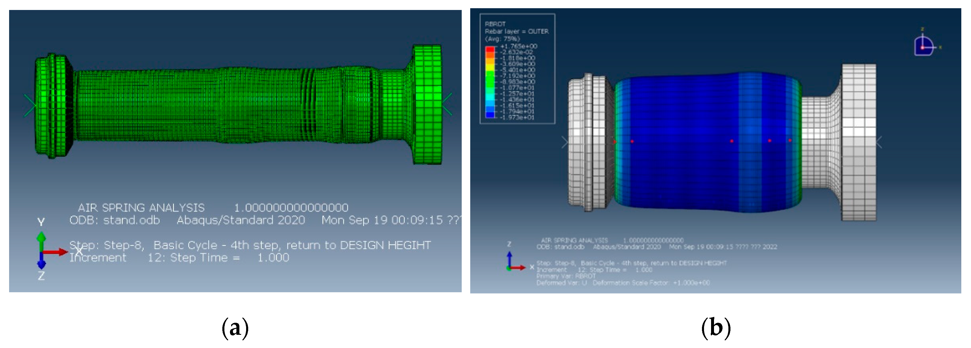
In addition to the changes in the manufacturing process, angle change also occurs during inflation and deformation. Pressurization and deformation analysis were performed on the sleeve-type airbag to verify that it fits well in the operation of the airbag. The analysis model is the same as that used by the authors of [10] for the passenger-car model. In this analysis, the reinforced fibers are modeled as rebar elements, and, as shown in Figure 6, the initial airbag has the same radius in the longitudinal direction, so it is easy to input according to the initial ply angle. Therefore, it is possible to check the change of the angle according to the analysis. In Figure 6b, which is a deformed shape, the ply angle change of five points was traced from the point close to the piston in the +x direction to the lower base.
The hollowed dot symbols in Figure 7 indicate the change of ply angle in the simulation as a radial position for the five points tracing the angle. Among the angle calculation equations, Figure 7 shows the case of Poisson’s ratio of 0.4 and 0.5 in Equation (3). Equation (1) has a large difference as the radial position increases, and Equations (2) and (3), using Poisson’s ratio, are considered to fit the change of ply angle well in the analysis. In particular, the Poisson’s ratio of 0.5 agrees better with the analyzed value.
According to the compression of the piston, the angle changes of the two points of the part that folds inward along the piston and the lower part of the airbag and three points that greatly deform outward in the airbag are shown in Figure 8a,b. In the case of using the rebar element, the angle is continuously tracked even in the area where the airbag is folded inward, and the case of using the Poisson’s ratio of 0.5 in Equation (3) is the most correct for the change value of the angle.
4. Effect of Angle Distribution on Air Spring Constants
4.1. Setup Ply Angle Distribution in ABAQUS
Unlike sleeve-type air springs, diaphragm-type air springs have different angles depending on their location, so even when using a rebar element, different angles must be set in the longitudinal direction from the upper plate to the lower plate. Because shell elements are mainly used in the analysis of air springs, the air springs are geometrically modeled with thick lines, as shown in Figure 9. In general, the height direction of the air spring is set as the y-axis, and the airbag is positioned in the x and z directions. If the coordinate system is defined based on (1,0,0) and (0,1,0), the normal direction of the shell is set in the direction of the cavity of the airbag. In order to define the angle of the ply, a cylindrical coordinate system must be set on the rebar element.
If the global origin is set as the origin of the cylinder coordinate system and the +y-axis is set as the reference axis, the direction 1 of the rebar element will change in two out of three areas, as shown in Figure 9. That is, in the Outer-Upper region and the Outer-Lower region, the normal vector of the shell element is in the −x direction, and in the Inner-Lower region, the direction 1 is opposite to the +x direction. Therefore, based on the longitude line, the rebar angle is 180 degrees different between the Outer-Upper or the Outer-Lower region and the Inner-Lower region. That is, if the ply angle based on the longitude line is set at ±16 degrees, it becomes 90 ± 16 degrees in the Outer-Upper or Outer-Lower region, and 270 ± 16 degrees in the Inner-Lower region.
Figure 10 shows the direction vector of the rebar element when the rebar element is used. Figure 10a shows the case where the ply angle is 0 degrees, and the sky-blue color indicates the fiber direction of the ply. Figure 10b shows the case where different ply angles are set for each position, and direction 2 (yellow color vector) is opposite to each other at the Outer-Lower region and Inner-Lower region interfaces.
4.2. Analysis Conditions and Results
In order to analyze the effect of the ply angle distribution on the characteristics of the air spring, a diaphragm-type air spring with the shape shown in Figure 4 was analyzed. The airbag used a full model without symmetry. This part will be explained through the results. The longitudinal direction of the airbag was divided into 110 shell elements, and the circumferential direction was divided into 50 pieces at intervals of 7.5 degrees. Since the ply angle using the rebar element is input for each element, the airbag was divided into a total of 110 element sets by grouping the elements in the circumferential direction into one set. The angle was written to the input file using programming. The airbag was divided into three regions by the method of the previous section, and the ply angle was entered according to the angle setting method in each region. The diameter of the reinforced fibers was 0.54 mm, and the spacing between fibers was inputted as 28EPI (EA/inch) at the inner bead part and 9EPI at the outer bead part.
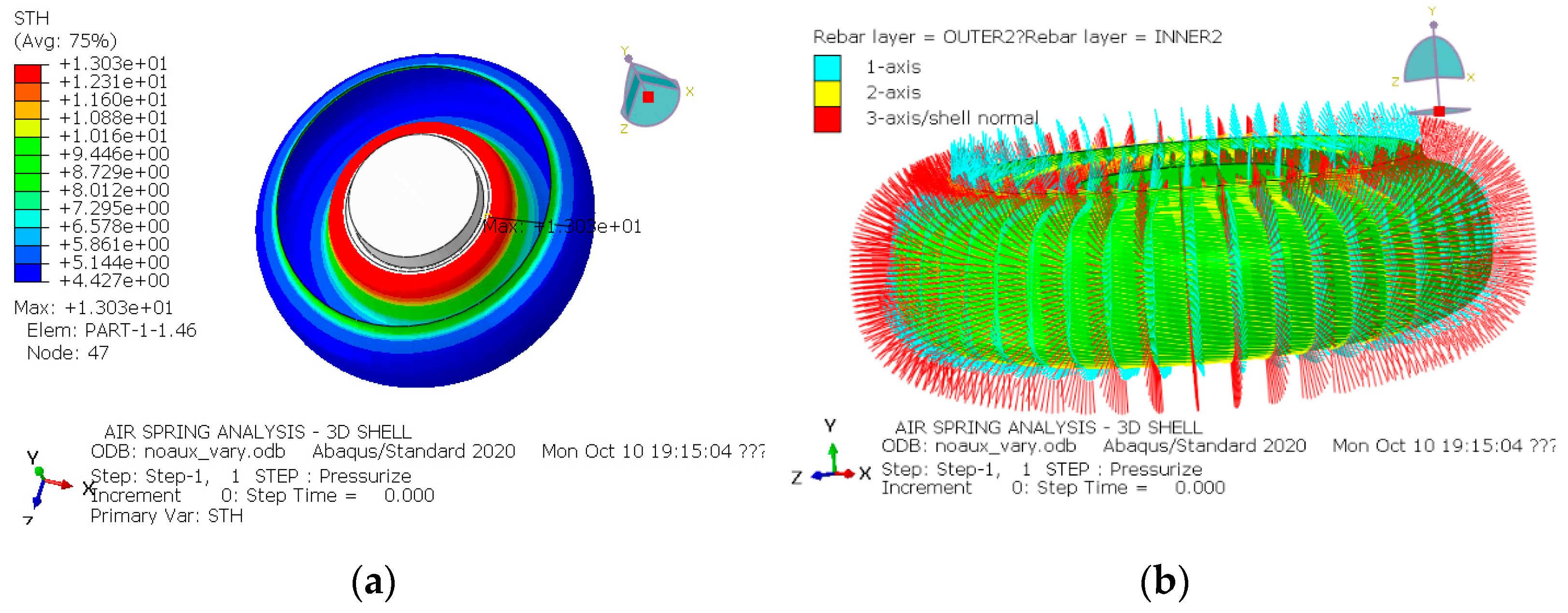
The thickness for each location was obtained through measurement. The average thickness of the airbag, excluding the vicinity of the upper and lower beads, is 4.7 mm, and has a maximum thickness of 13 mm at the lower bead and 8.5 mm at the maximum at the upper bead. The thickness distribution is shown in Figure 11a. The reinforcing fiber was nylon 66, and the reference [12] for mechanical properties was used.
The angle at the maximum radial position of the airbag was measured as 16 degrees. For the constant angle model, 16 degrees was set based on the maximum angle of the airbag. In order to obtain the angle calculated for each position, 267 mm, which is the radius of the upper bead, was used for the initial radial position, and 11 degrees was used for the initial angle to set the maximum angle of the airbag to 16 degrees. Using Equation (3) with the Poisson’s ratio of 0.5, the ply angle with respect to the radial position was obtained, as shown in Figure 3. The result of applying the angle to the rebar element is shown in Figure 11b using a vector.
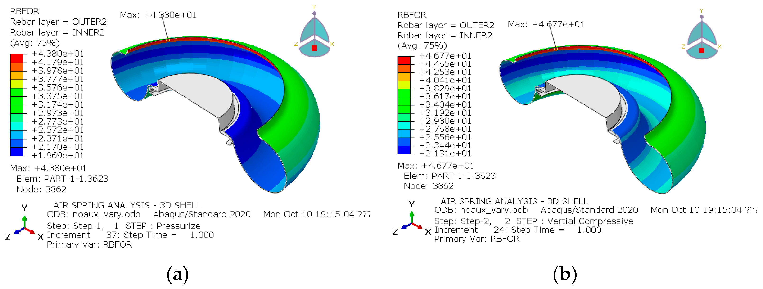
For analysis, after pressurizing to 6 bars, vertical compression, lateral deflection, and rotational twist were applied, sequentially. The rebar force distribution on the ply for each step of the variable ply angle case is shown in Figure 12, and the constant angle case is shown in Figure 13.
In Figure 12, where the angle is assigned as a constant, the maximum force applied to the ply appears in the airbag in the area close to the bottom plate. In the change of angle shown in Figure 3, the angle decreases toward the lower plate and should be placed parallel to the longitudinal axis by approximately 3 degrees. Therefore, when stretched in the circumferential direction by the internal pressure, the ply receives a large force. This has the effect of increasing the stiffness in the circumferential direction at the position of the inner airbag close to the bottom plate. The rebar force appears larger at a constant angle model, especially in torsion, which is 44.51N and 58.86N, which is up to 32% larger.
The characteristic diagram of the air spring is shown in Figure 14. As the internal pressure increases, the vertical force increases. In both cases, similar values are shown. When the internal pressure was 6 bars and the air flow was locked and the pressure was changed according to the volume, then vertical, lateral, and rotational loads were applied. In the case of vertical compression, there is not much difference between the two cases, but the lateral and rotational directions are significantly different. In the case of a constant angle, the reaction force/moment curve appears high in lateral deflection and rotational torsion, and the reaction force curve appears low in vertical load.
Table 1 summarizes the important spring characteristics for both cases. There is almost no difference in the vertical load and vertical stiffness at the internal pressure of 6 bars, and the outer diameter and height indicating the shape are also almost the same. However, in the variable ply angle model, the lateral stiffness was 24.3% lower, and the rotational stiffness was 30.2% lower than that of the constant angle model.
From this result, many of the existing analyzes that do not impose variable ply angles for each location mainly compared only the vertical stiffness and the outer shape, so that there were many results consistent with the experiment and the analysis. However, it can be seen that in order to study the lateral stiffness and torsional stiffness, the variable angles should be imposed for each position.
4.3. Discussion of Air Bag Modeling
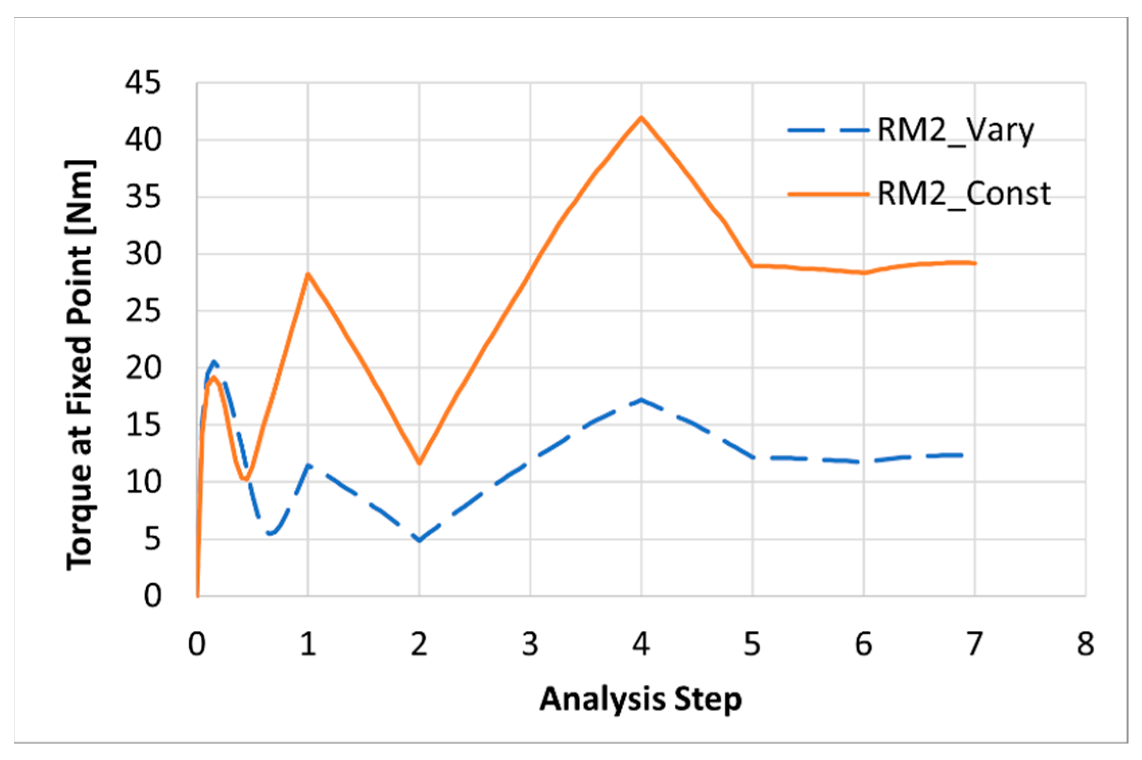
The torque at the fixing point of the lower plate is shown in Figure 15, according to the analysis steps. Step 1 is the pressurization and reference position, step 2 is compression, step 3 is the reference position, step 4 is tension, step 5 is the reference position, step 6 is lateral deflection, and step 7 is the reference position. Up to step 5, the load step is generally used to obtain the vertical stiffness, and usually axisymmetric or half-symmetry is used.
In Figure 15, even step 5 produces rotational torque, which means that it is not an axisymmetric or half-symmetric problem. The reason the torque appears is that the plies are attached symmetrically and assume that they are symmetrical, but in actuality, the plies are positioned differently in the radial direction. Therefore, even if the angles are the same, different results are displayed when a load is applied. Therefore, for a more accurate analysis, a full model analysis should be performed for airbag characteristic analysis.
5. Conclusions
In this study, it was proposed that equations for predicting the change in the ply angle by a radius position based on the ply angle and the initial radius during manufacturing of the air spring. Based on the thickness direction deformation, the maximum and minimum values of the ply angle change were presented, and an angle prediction equation using Poisson’s ratio was proposed. It was confirmed that the proposed equations were valid by comparing with the measurement angle of the diaphragm-type air spring. For sleeve-type springs in which the initial angle can be easily set for a finite element simulation, the ply angle change during deformation was calculated using the rebar element, and the prediction equations were shown to be valid by comparing them with the angle-prediction equation.
Finally, the spring stiffness and shape change were compared between the case where a constant angle was input for the diaphragm-type air spring and the angle input by the prediction equations. There was no difference in the vertical load, stiffness, and shape in both cases, but the difference in lateral stiffness and torsional stiffness was 24.3% and 30.2%, respectively. It was found that for accurate prediction, the variable ply angle had to be input differently for each location.
In the simulation of the air spring to predict the spring characteristics and deformation shape, it is necessary to trace the change in angle and input an appropriate angle according to the initial position. Otherwise, it may be possible to predict the load or stiffness in the vertical direction, but it is highly likely to fail in the prediction of the stiffness in the lateral and torsional directions. Practically, the angle in the initial shape can be obtained by measuring it after manufacturing, but it can be predicted in advance using the formula presented in this paper. According to the shape of the airbag, it is suggested that the angle for each position can be calculated by a formula, so air-spring researchers will be able to easily adopt it. In the air spring analysis, the angle should be entered based on the cylinder coordinate system, and the airbag section should be divided into regions and setup as suggested in this paper. In addition, it was suggested that the full air bag should be modeled for air spring analysis by confirming the occurrence of reaction torque at the fixed point.
Author Contributions
Conceptualization, H.L. and C.-S.K.; methodology, H.L.; software, H.L.; validation, H.L. and C.-S.K.; writing—original draft preparation, H.L.; writing—review and editing, C.-S.K.; project administration, C.-S.K. All authors have read and agreed to the published version of the manuscript.
Funding
This research was funded by Ministry of Land, Infrastructure and Transport of South Korea (Project No: RS-2020-KA162811).
Institutional Review Board Statement
Not applicable.
Informed Consent Statement
Not applicable.
Data Availability Statement
Not applicable.
Acknowledgments
This work was supported by DHM Co., Ltd. (dhm-korea.com, accessed on 1 July 2022). The authors would like to express their gratitude.
Conflicts of Interest
The authors declare no conflict of interest.
References
- Xu, L. Theoretical modeling of the vertical stiffness of a rolling lobe air spring. Sci. Progress. 2020, 103, 0036850420940898. [Google Scholar] [CrossRef] [PubMed]
- Li, X.; He, Y.; Liu, W.; Wei, Y. Research on the vertical stiffness of a rolling lobe air spring. Proc. IMechE Part F J. Rail. Rapid Transit. 2016, 230, 1172–1183. [Google Scholar] [CrossRef]
- Qi, Z.; Li, F.; Yu, D. A three-dimensional coupled dynamics model of the air spring of a high-speed electric multiple unit train. Proc. IMechE Part F J. Rail. Rapid Transit. 2016, 231, 1172–1183. [Google Scholar] [CrossRef]
- Lu, Z.; Si, P.; Xiao, H.; Liu, J. Influence of Aging Time on Vertical Static Stiffness of Air Spring. Appl. Sci. 2022, 12, 4219. [Google Scholar] [CrossRef]
- Lee, H.; Kim, S.; Huh, H.; Kim, J.; Jeong, S. Finite Element Analysis of Diaphragm-type Air Springs with Fiber-reinforced Rubber Composites. J. Compos. Mater. 2003, 37, 1261–1274. [Google Scholar] [CrossRef]
- Lee, H.; Huh, H. Finite Element Analysis of Air Springs with Fiber-Reinforced Rubber Composites Using 3-D Shell Elements. Trans. Korean Soc. Mech. Eng. A 2001, 25, 602–609. (In Korean) [Google Scholar]
- Toyokawa, S.; Shiozaki, M.; Yoshida, J.; Watanabe, D.; Sawa, T.; Haraguchi, H. Simulation Technology for Air Springs of Railway Systems. SEI Tech. Rev. 2020, 90, 13–16. [Google Scholar]
- Sarıoğlu, B.; Durmuş, A. Manufacture and Testing of Air Springs Used in Railway Vehicles. Arab. J. Sci. Eng. 2019, 44, 7967–7977. [Google Scholar] [CrossRef]
- Shi, W.; Jiang, W.; Huang, Y.; Yao, W.; Ya, H.; Liu, Z. Finite Element Analysis of an Air Spring Concerning Initial Pressure and Parameters of Cord Fabric Layer. In Proceedings of the 2009 Second Asia-Pacific Conference on Computational Intelligence and Industrial Applications, Wuhan, China, 28–29 November 2009; pp. 496–499. [Google Scholar]
- Lee, H.; Hahn, H.; Park, J. Static FE Analysis of Air Springs for Passenger Cars Considering the Mounting Steps. Trans. Mater. Process. 2015, 24, 387–394. [Google Scholar] [CrossRef] [Green Version]
- Weiser, S.; Lehmann, T.; Landgraf, R.; Goldberg, N.; Donner, H.; Ihlemann, J. Experimental and numerical analysis of cord–elastomer composites. J. Rubber. Res. 2021, 24, 211–225. [Google Scholar] [CrossRef]
- Li, X.; Wei, Y.; Feng, Q.; Luo, R. Mechanical behavior of nylon 66 tyre cord under monotonic and cyclic extension: Experiments and constitutive modeling. Fibers Polym. 2017, 18, 542–548. [Google Scholar] [CrossRef]
Figure 1.
Measured cord angles of the 684N diaphragm-type air spring at the designated points from the reference [5].
Figure 1.
Measured cord angles of the 684N diaphragm-type air spring at the designated points from the reference [5].

Figure 2.
Conceptual diagram of angle prediction equations.

Figure 3.
Calculated ply angles from Equation (1) to Equation (3) at , .

Figure 4.
Air bag model for angle calculation and analysis.

Figure 5.
Comparison of ply angle measured from 684N diaphragm air spring and angle distribution using angle calculation equation: (a) 1st ply (inner); (b) 2nd ply; (c) 3rd ply; (d) 4th ply; (e) 5th ply; (f) 6th ply.
Figure 5.
Comparison of ply angle measured from 684N diaphragm air spring and angle distribution using angle calculation equation: (a) 1st ply (inner); (b) 2nd ply; (c) 3rd ply; (d) 4th ply; (e) 5th ply; (f) 6th ply.

Figure 6.
Analysis model of a passenger car air spring [10] and the 5 points to trace: (a) initial model; (b) deformed shape.
Figure 6.
Analysis model of a passenger car air spring [10] and the 5 points to trace: (a) initial model; (b) deformed shape.

Figure 7.
Angle calculation results and simulation results during inflation and compression analysis in sleeve-type air spring: (a) Equations (1)–(3) with Poisson’s ratio of 0.5; (b) Equations (1)–(3) with Poisson’s ratio of 0.4.
Figure 7.
Angle calculation results and simulation results during inflation and compression analysis in sleeve-type air spring: (a) Equations (1)–(3) with Poisson’s ratio of 0.5; (b) Equations (1)–(3) with Poisson’s ratio of 0.4.

Figure 8.
Angle calculation results and simulation results during inflation and compression analysis in sleeve-type air spring: (a) 2 outer points; (b) 3 middle points.
Figure 8.
Angle calculation results and simulation results during inflation and compression analysis in sleeve-type air spring: (a) 2 outer points; (b) 3 middle points.

Figure 9.
Domain definition of an air bag for variable ply angle setup.

Figure 10.
Rebar element direction (vector of sky-blue color) in the shell element: (a) setup with angle of 0 degree; (b) setup with variable ply angles.
Figure 10.
Rebar element direction (vector of sky-blue color) in the shell element: (a) setup with angle of 0 degree; (b) setup with variable ply angles.

Figure 11.
Initial conditions of air spring analysis: (a) Distribution of thickness; (b) Vector distribution for ply angles in variable ply angle model.
Figure 11.
Initial conditions of air spring analysis: (a) Distribution of thickness; (b) Vector distribution for ply angles in variable ply angle model.

Figure 12.
Distribution of rebar force (RBFOR) during analysis at variable ply angle distributions: (a) inflation; (b) vertical compression; (c) lateral deflection; (d) torsional rotation.
Figure 12.
Distribution of rebar force (RBFOR) during analysis at variable ply angle distributions: (a) inflation; (b) vertical compression; (c) lateral deflection; (d) torsional rotation.


Figure 13.
Distribution of rebar force (RBFOR) during analysis at constant ply angle distributions: (a) inflation; (b) vertical compression; (c) lateral deflection; (d) torsional rotation.
Figure 13.
Distribution of rebar force (RBFOR) during analysis at constant ply angle distributions: (a) inflation; (b) vertical compression; (c) lateral deflection; (d) torsional rotation.

Figure 14.
Variation of characteristic data for the air spring simulation: (a) Vertical force vs. internal pressure; (b) Vertical force vs. compressive deflection; (c) Lateral force vs. lateral deflection; (d) Torque vs. rotation.
Figure 14.
Variation of characteristic data for the air spring simulation: (a) Vertical force vs. internal pressure; (b) Vertical force vs. compressive deflection; (c) Lateral force vs. lateral deflection; (d) Torque vs. rotation.

Figure 15.
Variation of torque at fixed point with respect to analysis steps according to angle distribution.
Figure 15.
Variation of torque at fixed point with respect to analysis steps according to angle distribution.


Table 1.
Comparisons of characteristic data with respect to the ply angle variation for the air spring analysis at inflating pressure of 6 bars.
Table 1.
Comparisons of characteristic data with respect to the ply angle variation for the air spring analysis at inflating pressure of 6 bars.
| Characteristic Data | Constant Ply Angle | Variable Ply Angle | Difference Ratio |
|---|---|---|---|
| Vertical Force (kN) | 128.6 | 130.6 | 1.5% |
| Vertical Stiffness (N/mm) | 850.6 | 880.2 | 3.5% |
| Lateral Stiffness (N/mm) | 99.1 | 75.0 | −24.3% |
| Torsional Stiffness (Nm/Deg.) | 450.2 | 314.1 | −30.2% |
| Outer Diameter (mm) | 676 | 678 | 0.3% |
| Height (mm) | 178.7 | 176.8 | −1.1% |
Publisher’s Note: MDPI stays neutral with regard to jurisdictional claims in published maps and institutional affiliations. |
© 2022 by the authors. Licensee MDPI, Basel, Switzerland. This article is an open access article distributed under the terms and conditions of the Creative Commons Attribution (CC BY) license (https://creativecommons.org/licenses/by/4.0/).
Share and Cite
MDPI and ACS Style
Lee, H.; Kim, C.-S. Prediction of Ply Angles of Air Springs According to Airbag Positions and Their Effects on Lateral and Torsional Stiffness. Appl. Sci. 2022, 12, 11815. https://0-doi-org.brum.beds.ac.uk/10.3390/app122211815
AMA Style
Lee H, Kim C-S. Prediction of Ply Angles of Air Springs According to Airbag Positions and Their Effects on Lateral and Torsional Stiffness. Applied Sciences. 2022; 12(22):11815. https://0-doi-org.brum.beds.ac.uk/10.3390/app122211815
Chicago/Turabian StyleLee, Hyoungwook, and Chul-Su Kim. 2022. "Prediction of Ply Angles of Air Springs According to Airbag Positions and Their Effects on Lateral and Torsional Stiffness" Applied Sciences 12, no. 22: 11815. https://0-doi-org.brum.beds.ac.uk/10.3390/app122211815
Note that from the first issue of 2016, this journal uses article numbers instead of page numbers. See further details here.