
Vibration from Electric Hand-Held Harvesters for Olives


Department of Agriculture, Food and Environment (Di3A), Section of Mechanics and Mechanization, University of Catania, Via Santa Sofia, 100, 95123 Catania, Italy
*
Author to whom correspondence should be addressed.
Appl. Sci. 2022, 12(4), 1768; https://0-doi-org.brum.beds.ac.uk/10.3390/app12041768
Submission received: 23 January 2022
/
Revised: 3 February 2022
/
Accepted: 5 February 2022
/
Published: 9 February 2022
(This article belongs to the Special Issue Worker Safety in Agricultural Systems)
Abstract
:Featured Application
Portable harvesters for olive harvesting expose workers to high vibration risks to the hand-arm system. With the same harvester head, reduction in vibration may be achieved by using carbon fiber rods rather than aluminum ones or by increasing the rod diameter. However, the most significant reduction in vibration level is achieved by designing harvester heads whose kinematics inherently incorporate oscillation compensation.
Abstract
Olive harvesting is the most expensive cultivation operation in areas where full mechanization is not possible due to structural conditions such as low tree density, old trees, irregular spacing, and terraced fields, which are very frequent in many small Italian farms. Under these conditions the use of hand-held vibrating harvesters is quite wide spread, because they are capable of approximately three times the productivity of workers using manual harvesting methods. Unfortunately, the use of these machines exposes the operators to hand-arm vibration risk and acceleration values are affected by several factors, including harvester kinematics, rod material and geometry, and load conditions. In this study several models of electrical portable harvesters, obtained by combining six harvester heads and four rods (one telescopic), were tested under idling and load conditions, measuring acceleration values on the rod, near the hand positions. Assuming the use of the machinery for 4 h per day, the result is a level of daily vibration exposure A(8) for the most exposed hand ranging from about 11 to 40 m/s2, much higher than the daily exposure limit value of 5 m/s2 stated by the European Directive 2002/44/EC. With the same harvester head, reduction in vibration may be achieved by using carbon fiber rods rather than aluminum ones or by increasing the rod diameter. The most significant reduction is achievable by designing harvester heads whose kinematics inherently incorporate oscillation compensation.
1. Introduction
Olive cultivation in Italy produces approximately 2,500,000 tons and the cultivated surface is about 1,160,000 ha [1], mainly concentrated in the centre-south of the peninsula. According to FAO statistics [2], Italy, alongside Spain, Greece, and Turkey, is among the major producers of olive oil in the Mediterranean basin.
However, olive cultivation incurs high production costs, mainly during the harvesting phase. A recent study by Sperandio et al. [3] analyzed several scenarios and reported harvesting costs of around 3300 EUR/ha with manual harvesting, 1720–1980 EUR/ha with the use of hand-held equipment, 920–1350 EUR/ha with the use of trunk-shakers and ground nets, 660–1060 EUR/ha using trunk-shakers equipped with collecting umbrella, and 330–500 EUR/ha using self-propelled straddle harvesters in super-intensive groves. Harvesting costs decrease with the increase in mechanization level.
The mechanization of the harvesting of olive groves characterized by low tree density, old trees, irregular spacing, located in marginal areas, in some cases terraced and impracticable, such as that present in many Italian regions, is a very difficult task [4]. The most appropriate level of mechanization should be chosen in a manner closely connected with technical-organizational factors such as the structural characteristics of the territory and of the farm [5]. In olive groves where high levels of mechanization are not possible, the use of hand-held vibrating harvesters is quite spread. These machines are approximately capable of increasing by three times the productivity of workers using manual harvesting methods, and they also reduce harvesting costs [6].
The use of vibrating equipment, both portable and self-propelled, is very common in agriculture for harvesting operations of a wide range of products. Unfortunately, the workers, when using these machines, are mainly interested in productivity, and very often they underestimate ergonomics and safety aspects. Vibration of the hand-arm system is probably the most important risk connected with the use of portable harvesters and vibrating tools in general [7,8,9,10,11,12]. Exposure to hand-arm vibration may result in several chronic disorders such as sensory, vascular, and musculoskeletal symptoms, recognized by several names: secondary Raynaud’s phenomenon, vibration white finger, dead finger, traumatic vasospastic disease, and vibration syndrome, collectively known as Hand-Arm Vibration Syndrome (HAVS) [13,14,15,16,17,18]. If detected in the early states, HAVS is reversible by reducing or eliminating further exposure to vibration, but, once in an advanced stage, symptoms are progressive, and treatment is usually ineffective [19]. Moreover, as recently established [20,21], exposure to vibration leads to the production of reactive oxygen species that, in turn, can cause damage to biomolecules, including DNA. DNA damage is known to lead to carcinogenesis, teratogenesis and premature aging, so vibration risk exposure should be promptly recognized and properly managed.
The transmission of the vibration and its propagation in the organism through the hand-arm system is a complex phenomenon that involves several factors, including biodynamic characteristics [22,23], mechanical impedance of the hand [22,24,25], posture [26,27], muscle tension and hand forces [28,29], handle size [29], use of isolators [30], which interact with the intensity of the vibration and its transmissibility [31]. Considering the vibration produced by portable harvesters for olives, the kinematics of the harvester head, the rod material, its geometry (length and diameter), and its configuration (fixed length or telescopic) play a key role. Other important aspects to be considered are the working conditions (idling or full-load) and the operator characteristics (weight, grip force, ability), so the assessment of the effective risk requires direct measurement under real working conditions or the definition of standardized procedures able to provide reliable acceleration values [32,33].
In this paper several models of electrical portable harvesters for olives are tested under idling and load conditions and vibration values transmitted to the hand-arm system are reported.
2. Materials and Methods
2.1. The Hand-Held Harvesters
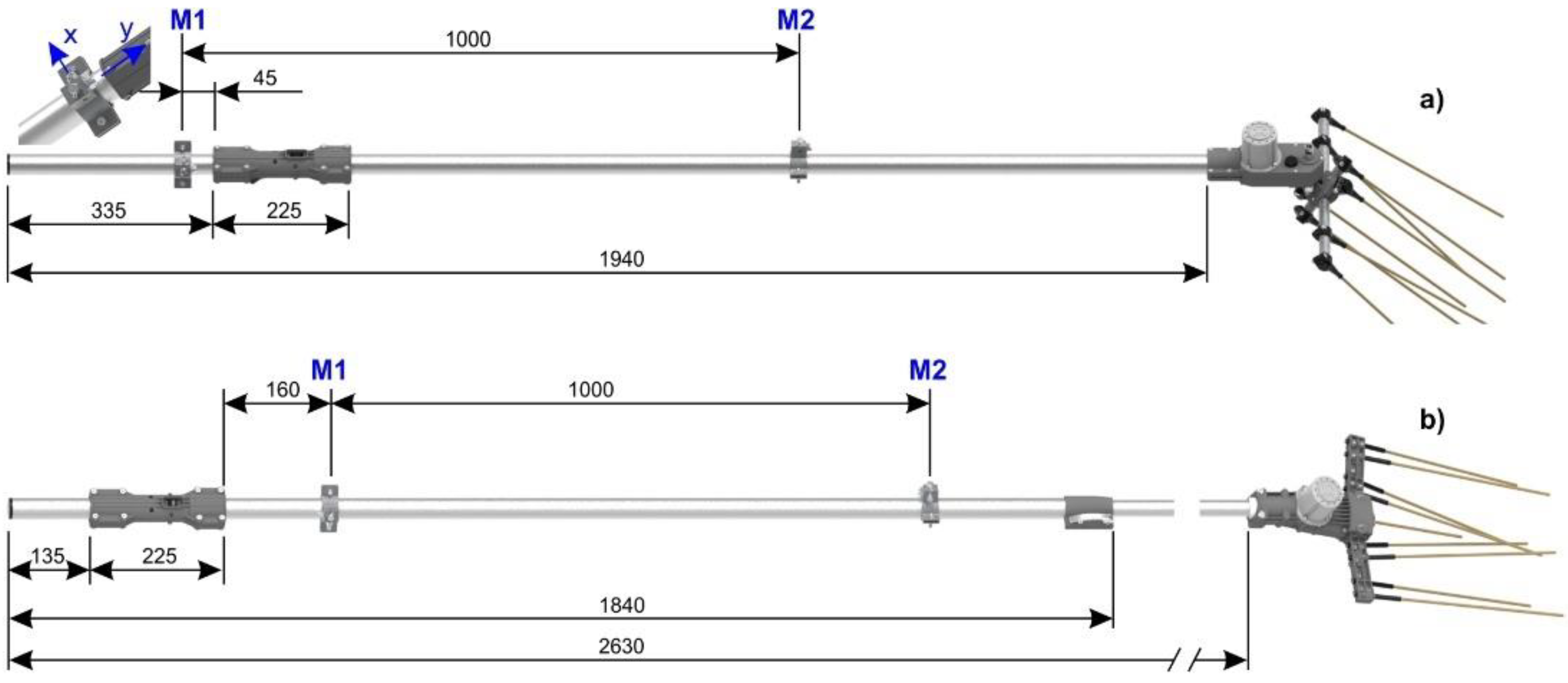
The portable harvesters considered in this study were obtained from a local manufacturer and assembled by combining six harvester heads (Table 1) and four rods, one of which is telescopic (Table 2). For the sake of simplicity, the telescopic rod was considered as two distinct rods. In Table 2, total rod length includes the handle length (225 mm) and a rear extension (335 mm (R1, R2 and R3) or 135 mm (R4–R5)). The resulting portable harvesters and the operating conditions are summarized in Table 3.
The harvesting heads differ in number, length, and arrangement of the sticks (all in carbon fibre), as well as in the direction of the oscillations. All are driven by a 12 V DC electric motor (maximum power of 900 W and rotating speed of around 6300 rpm, fixed by an electronic card), powered by means of an external battery; the electric cable is placed inside the rod, from which it emerges in correspondence with the hand-grip equipped with the activation switch. The motor shaft is connected to a box, that together with a gear ratio of 10:58, moves the arms with the sticks with an oscillating frequency of about 18 Hz.
The H1, H2, and H3 models have an aluminum box and the same mechanism to activate the sticks. The sticks are attached to a 360 mm main arm that in H1 and H2 is disposed orthogonally to the motor shaft, whereas in H3 is coaxial, so the oscillating planes are orthogonal. In particular, the 12 sticks of H3 are arranged in the classical flap-type shape, widely used in older pneumatic models.
The harvesting heads H4, H5, and H6 have a plastic box to which are connected two arms with opposing oscillations on a plane orthogonal to the motor shaft. They differ in number of sticks per arm (4 in H4 and H5, 7 in H6), arm length (168 mm in H4 and H6, 121 mm in H5) and stick length (330 mm in H4 and H6, 360 in H5).
The harvester heads H1, H2 and H3 were applied to the rods R1, R2 and R3 in a crossed experiment. This allowed the study of the interaction between the kinematics of the harvester heads, features of the rods (material, diameter), and the test conditions (idling, load). The harvester heads H4, H5 and H6 were applied to the same rod (R4–R5) and this allowed the study of the behavior of one telescopic rod (R4: minimum length, R5: maximum length) with different harvester heads (but with similar kinematics) under different test conditions (idling, load). Considering the couple (harvester head, rod) as a single portable harvester, globally 15 portable harvesters were tested.
2.2. The Experimental Activity
All the portable harvesters were operated by the same person (mass 84 kg, height 1.67 m, expert in using the machines) to limit the influence of operator features and all were tested both at idling and load conditions.
Idling measurements were carried out considering three rod angles: 90° (vertical), 45° (inclined), and 0° (horizontal) with respect to the horizontal plane, to cover all the practical conditions during harvesting. Load tests were carried out simulating the harvesting, by inserting the sticks of the harvester heads into an olive tree canopy for a few seconds and then moving the harvester head to another position to repeat the operation. Each test condition was replicated 5 times and each measurement lasted about 60 s.
Vibration was measured, at different times, near to the position of the hands: rear position (M1, near to the hand-grip with the activation switch) and front position (M2, on the rod). During harvesting, the operator continuously changes his hand position along the rod, so the distance between the two measuring points M1 and M2 was standardized at 1 m (Figure 1).
2.3. The Acceleration Acquisition System
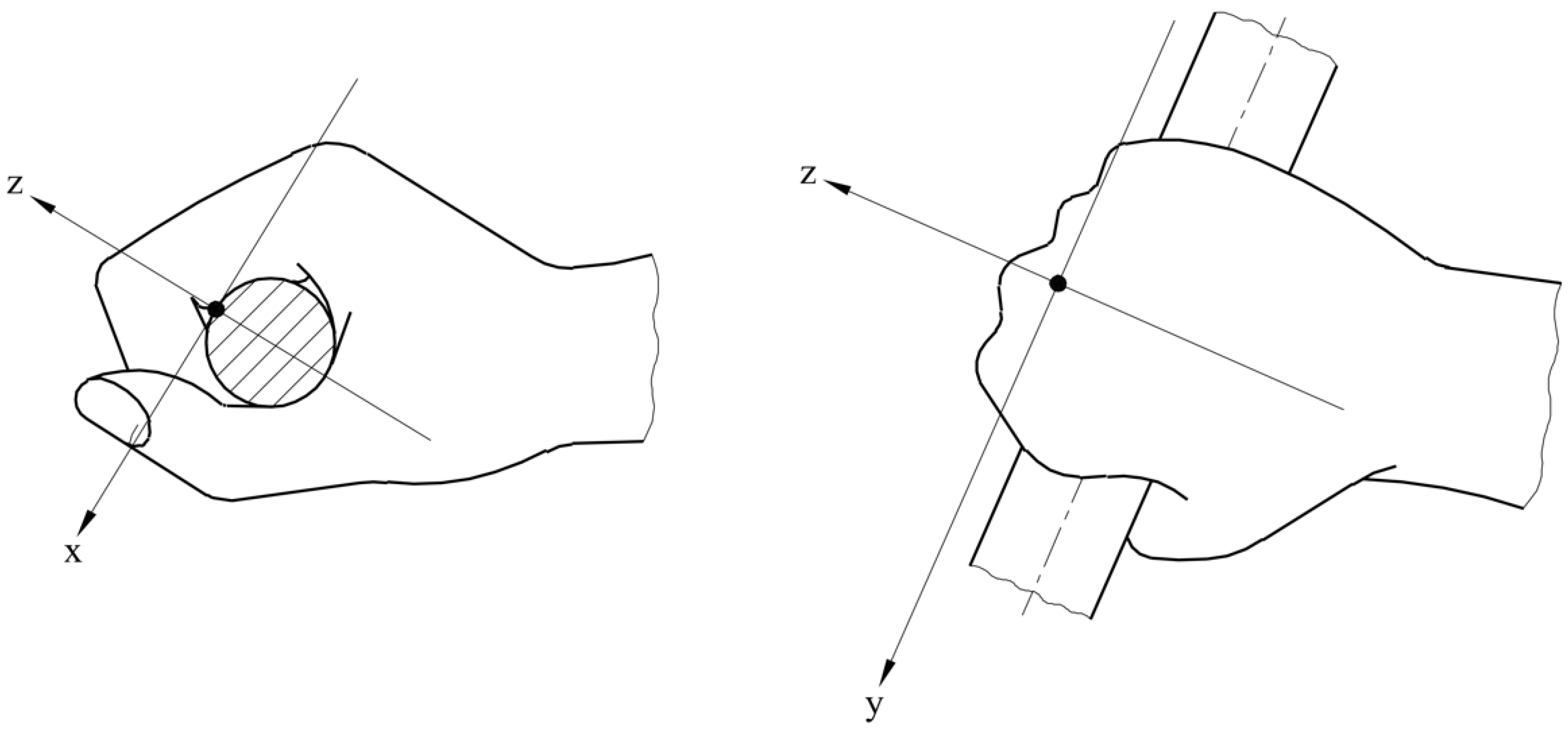
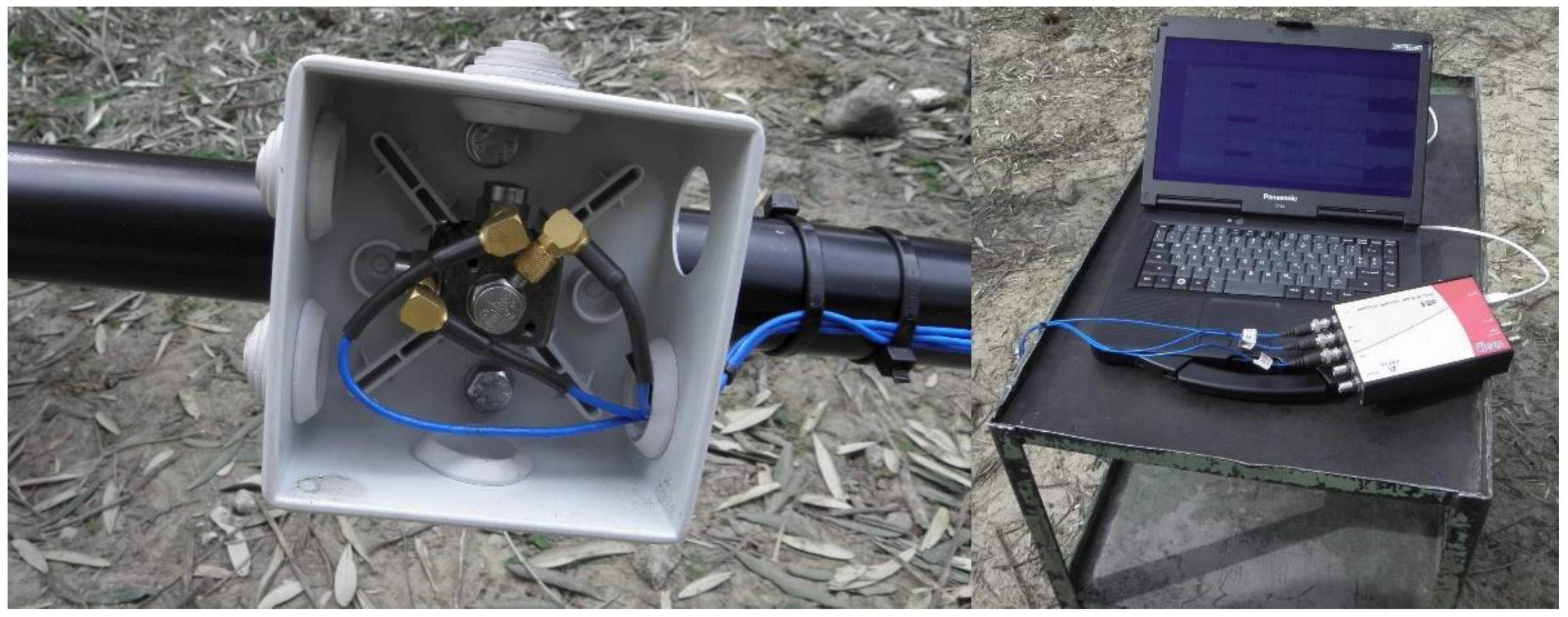
Acceleration values were measured by means of three mono axial accelerometers (DJB, model A/123/S, DJB Instruments Ltd., Suffolk, UK, nominal sensitivity 10 mV/g, 1 g = 9.81 m/s2), screwed onto the faces of a small cube attached to the rod with a metallic clamp. The reference axes were fixed according to the basicentric coordinate system defined by the EN ISO 5349-1:2001 regulation [34]: x-axis perpendicular to the palm surface area, y-axis parallel to the longitudinal axis of the grip, and z-axis directed along the third metacarpus bone of the hand (Figure 2). To respect this constraint and considering the different orientation of the palm of both hands, at least under static conditions, the accelerometers were arranged differently in the two measuring points. However, during harvesting, the operator continuously changed hand position and harvester orientation, so x- and z-axes could not respect the basicentric coordinate system.
The accelerometer signals were sampled at a frequency of 5000 Hz and then recorded on the hard disk of a PC by means of a four-channel PC-based acquisition unit (Figure 3). The acquisition system was managed by the dBFA Suite software (01dB-Metravib, Lyon, France).
Before and after each measurement session, the measurement chain was calibrated by means of a vibration exciter (RION Co., LTD., mod. VE-10, Tokyo, Japan), which generated a sinusoidal output acceleration signal of 10 m/s2 (root mean square, rms) at the frequency of 159.2 Hz.
2.4. Signal Analysis and Data Processing
According to EN ISO 5349-2:2001 [35], vibration is expressed in terms of root mean square frequency weighted acceleration. So, the recorded acceleration signals were post-processed in the laboratory by using the post-processing module of the same dBFA Suite software. Broad band (one-third octave) analysis was applied in the frequency range 6.3–1250 Hz for each reference axis. In addition, narrow band analysis (Fast Fourier Transform, FFT) was applied in the range 0–1800 Hz to identify the frequency of the main harmonics. Linear acceleration values from the broad band analysis were used to obtain the frequency weighted acceleration values according to the Equation (1):
where (m/s2) is the rms acceleration value measured in the i-th one-third octave band and the corresponding weighting factor (Table 4). All the computations were implemented in the dBFA Suite software.
Acceleration total value, (m/s2), was computed as the root-sum-of-squares of the three component values (Equation (2)):
where , and (m/s2) are the rms frequency weighted acceleration values for the three reference axes.
The CEN/TR 15350:2013 (European Committee for Standardization, 2013 [36]), for the measurement of the vibration emission for flap type fruit harvesters, recommends weighting idling and full-load acceleration total values to calculate the equivalent vibration total value (m/s2) according to Equation (3):
with weighting factors and the respective daily exposure fraction times. However, the measurements under load conditions considered in this study already take into account the fraction times of idle running that occur when the operator moves the harvester head to different points of the tree canopy during the harvesting. So, the acceleration total value obtained from Equation (2) was treated as the equivalent vibration total value and used to calculate the daily vibration exposure according to the Equation (4):
where T is the total daily exposure duration (h) and the reference time (8 h). Considering a standard 7 h working day, the average daily exposure time may be assumed to range from 3 to 5 h [37,38], being the residual time used for the positioning of the nets and the recovery of the final product. In this study T was assumed equal to 4 h.
Given the experimental design, acceleration total values were analyzed separately for harvester heads H1–H3 with rods R1–R3 and harvester heads H4–H6 with rods R4–R5, both as crossed experiments. Due to the high number of factors (harvester head, rod, measuring point, rod angle, load conditions), the study was limited to the first order interactions considered of interest. The significance of differences between mean values was assessed by applying the Kruskal–Wallis non-parametric test. All statistical analyses and graphical representations were carried out using the open source software R [39] (R Core Team, 2021).
3. Results
3.1. Harvester Heads H1–H3 with Rods R1–R3
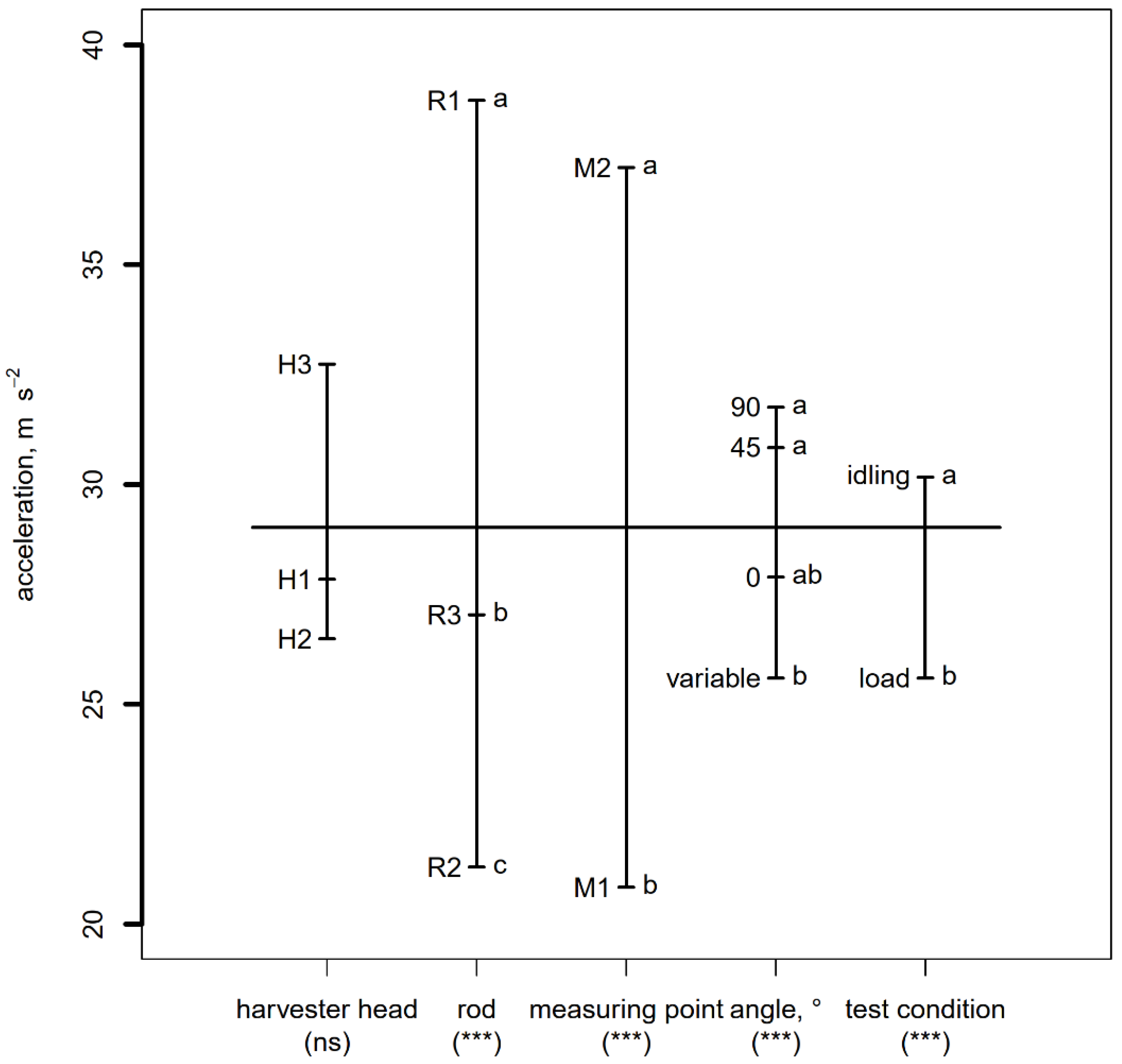
Figure 4 summarizes the mean acceleration total values with respect to the main factors analyzed in the study.
Considering the harvester heads, mean acceleration total value ranged from 26.49 m/s2 (H2) to 32.76 m/s2 (H3). However, according to the Kruskal–Wallis test, differences between the harvester heads were not statistically significant. The differences due to the rod type were statistically significant. The highest acceleration total value (38.76 m/s2) was measured with the rod R1 (aluminum made, 35 mm diameter), the intermediate value (27.04 m/s2) with the rod R3 (aluminum made, 40 mm diameter), and the lowest (21.30 m/s2) with the rod R2 (carbon fiber made, 40 mm diameter). These results suggest that, with the same material (aluminum), vibrations are reduced as the rod diameter increases, whereas with the same diameter (40 mm), carbon fiber reduces vibration with respect to the aluminum. The difference between the two measuring points was significant. The highest acceleration total value was measured in the front position (M2, 37.21 m/s2) and the lowest in the rear position (M1, 20.84 m/s2), implying different exposure of the operator’s hands. The differences between the three rod angles under idling conditions were not statistically significant: 31.76 m/s2 at 90°, 30.84 m/s2 at 45°, and 27.89 m/s2 at 0°. The “variable” angle in Figure 4 refers to tests under load conditions. On average, idling conditions were more stressing than load conditions, 30.16 vs. 25.60 m/s2, respectively.
The interactions between the harvester head and the other main factors are summarized in Table 5.
Considering the head × rod interaction, it emerged that the predominant factor was the rod type. With the same rod, the acceleration values were not statistically different among the three harvester heads. The highest value (45.74 m/s2) was measured with the harvester head H3 (the flat-type model) when used with the rod R1 (aluminum, 35 mm diameter). The differences within the head × rod angle interaction were significant for only a few cases regarding the tests under load compared to the idling tests. More specifically, the lowest acceleration total value (23.70 m/s2) was measured under load conditions with the harvester head H2, whereas the highest values were measured with the harvester head H3 under idling conditions at 90° (42.16 m/s2) and at 45° (31.39 m/s2). Finally, acceleration values in the front position (measuring point M2) were significantly higher than in the rear position (measuring point M1) for all the three harvester heads.
3.2. Harvester Heads H4–H6 with Rods R4–R5
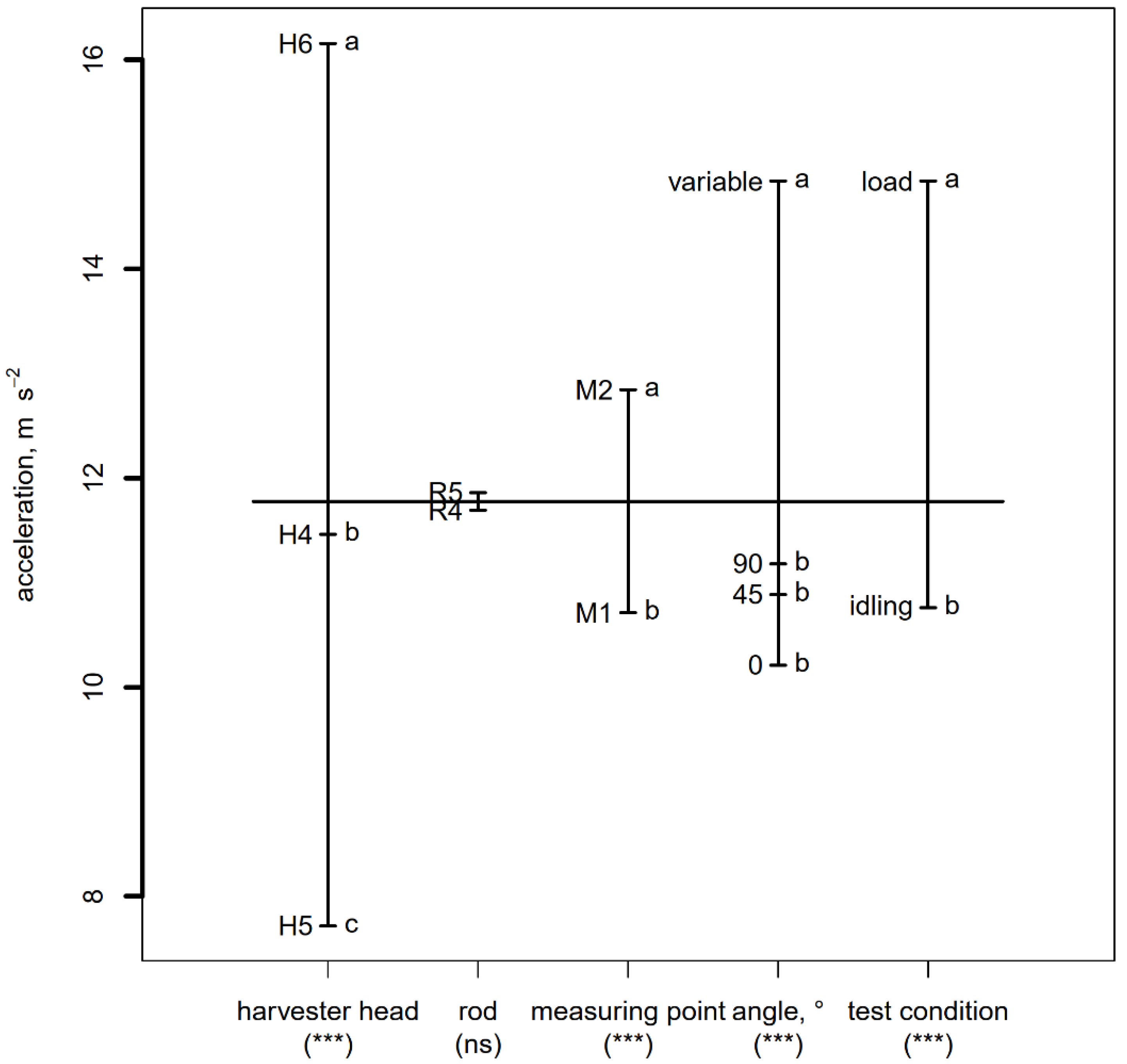
The plot-design in Figure 5 summarizes the mean acceleration total values measured with the harvester heads H4–H6. Average values ranged from 7.72 m/s2 (H5) to 16.15 m/s2 (H6), much lower than those measured with harvester heads H1–H3. Demonstrating that the different kinematics of the harvester H4–H6 with respect to H1–H3 contributed enormously to the reduction of the vibration transmitted to the hand-arm system.
The differences between the two rods were not statistically significant, 11.69 m/s2 with R4 (telescopic, minimum length) and 11.86 m/s2 with R5 (telescopic, maximum length). Acceleration in the front position (M2, 12.85 m/s2) was again significantly greater than in the rear position (M1, 10.71 m/s2). The comparison among the three rod angles under idling conditions confirmed the results obtained with harvester heads H1–H3. Even if not statistically significant, there was a decreasing trend in acceleration values as the angle decreased from 90° (11.18 m/s2) to 0° (10.21 m/s2). However, contrary to what was measured with the harvester heads H1–H3, the acceleration under load conditions (14.84 m/s2) was significantly greater than that under idling conditions (10.76 m/s2).
Table 6 summarizes the interactions between the harvester head and the other main factors. The interaction with the rod was not statistically significant, in fact, for all rods the result was the same for the three harvester heads (highest acceleration for H6, intermediate for H4, lowest for H5). The head × rod angle interaction revealed that the harvester head H6 produced the same acceleration both under idling and load conditions, ranging from 15.30 to 16.78 m/s2, whereas for the other two harvesting heads vibration under load conditions was significantly greater than under idling conditions. Finally, the interaction head × measuring point was not statistically significant. The acceleration values in the front position were always greater than in the rear position, for all the harvester heads.
3.3. Acceleration Components
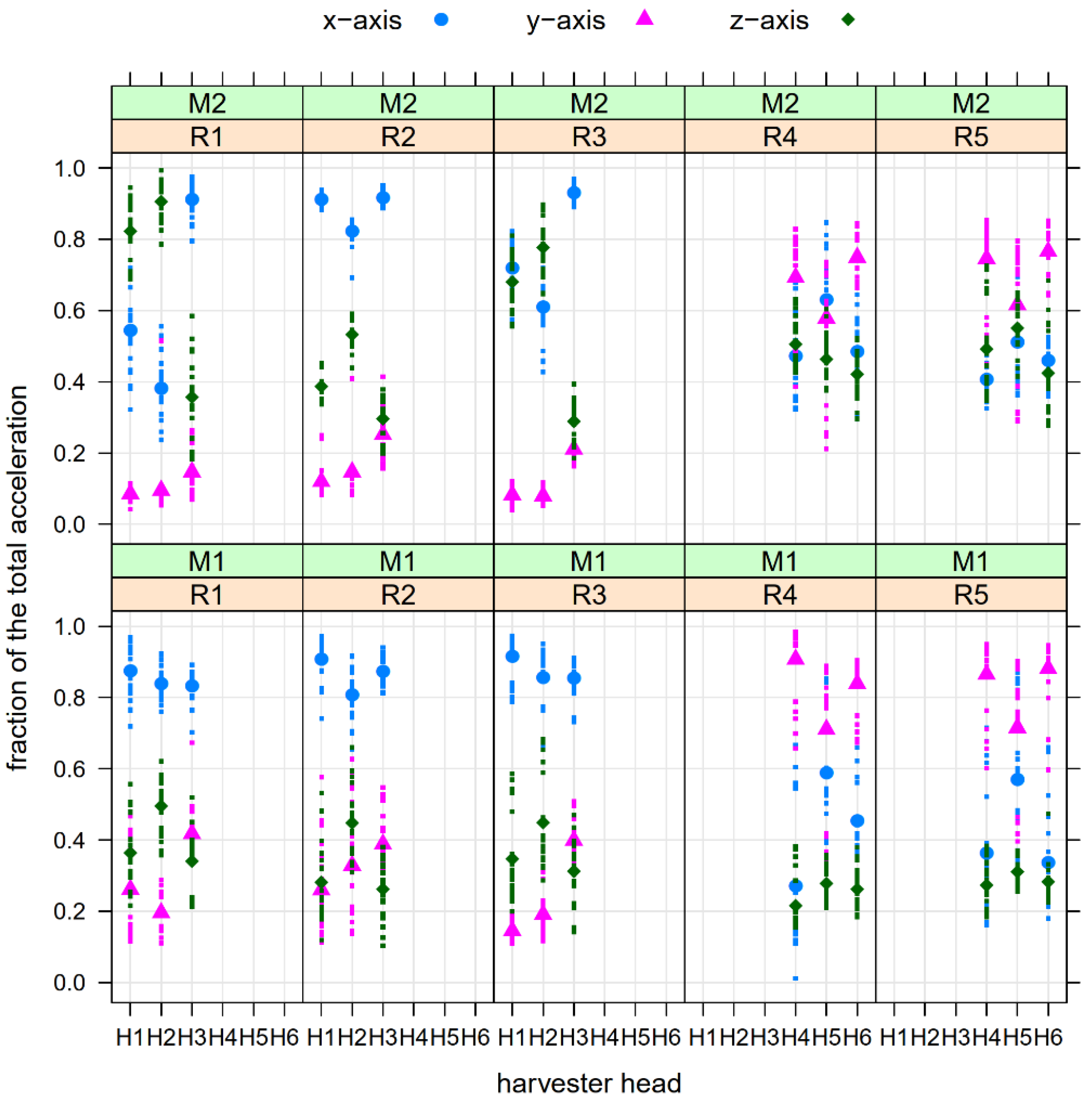
Figure 6 reports the fraction of the acceleration total value due to the j-axis component for each harvester head, defined as:
Considering the harvester heads H1–H3, Figure 6 shows that in the rear position (M1) the main acceleration component was always that along the x-axis, accounting for 81–92% of the acceleration total value at varying the rod. The lowest component was that along the y-axis for harvester heads H1 and H2 and that along the z-axis for harvester head H3. In the front position (M2) the lowest component was always that along the y-axis, whereas the main component was affected by the rod type. When the carbon fiber rod (R2) was used, the main acceleration component was again that along the x-axis (from 82 to 92%), whereas when the aluminum rods were used, the z-axis component was predominant for the harvester heads H1 and H2.
When the harvester heads H4–H6 were used, the y-axis component was almost always predominant in both measuring points, accounting for 58–77% of the acceleration total value in the rear position and for 71–91% in the front position.
Results on the acceleration components were strictly correlated with the harmonic content of the signals. As an example, Figure 7 shows the FFT spectra of the harvester heads H1–H3 applied to the rod R2 (carbon fiber) and H4–H6 applied to the rod R4 (telescopic, minimum length). To better analyze the results and highlight the main differences between and within the two groups of harvester heads, all FFT spectra were computed under idling conditions and in the most exposed measuring point (front position, M2). In addition, the frequency range in the plot was limited to 0–200 Hz, the effect of the higher frequencies being attenuated by the weighting curves stated by the EN ISO 5349-1:2001 regulation (Table 4).
As it might be expected, the frequency of the first harmonic was around 18 Hz for all the harvester heads. In fact, all the machines were driven by the same engine model, the kinematics of the initial part of the motion transmission system was the same, as well as the reduction ratio. Comparing the acceleration values at the different frequencies, it is possible to point out that the arrangement of the arms carrying the sticks with respect to the transmission box had a significant effect on the results. In fact, with the harvesting heads H1 and H2, where the main arm oscillates orthogonally to the motor shaft, the highest acceleration values were recorded along x- and z-axes. Instead, in H3 the sticks oscillate around the motor shaft and this has resulted in an increase in acceleration values along the y-axis and in a decrease along the z-axis. In addition, the different disposition of the sticks in H2 with respect to H1 made the harmonics between 100 and 200 Hz of higher amplitude.
The FFT spectra of the harvester heads H4–H6 were all characterized by harmonics of lower amplitude along the x- and z-axes and higher amplitude along the y-axis with respect to H1–H3, and this can be attributed to the opposite movement of the two arms carrying the sticks. In addition, all the spectra showed the presence of harmonics fairly uniformly along a wide range of frequencies, indicating a more widespread distribution of the energy levels. Comparing H4 and H6, which differ only in the number of sticks, it emerged that the greater the number of sticks, and then of the oscillating masses, the higher the acceleration values at almost all frequencies. Finally, comparing H4 and H5, which differ mainly in the length of the oscillating arms, and then in the distance of the sticks from the center of oscillation, it emerged that the shorter the length of the arms, the lower the acceleration values at all the main frequencies.
4. Discussion
Vibration exposure is the major physical risk resulting from the use of electrical portable harvesters. Noise risk has been greatly reduced due to the use of electric motors [10] in substitution of pneumatic drives [40] or internal combustion engines [41]. Measured acceleration values may vary significantly depending on harvester head kinematics, rod features, load conditions, and user ability. Unfortunately, in many situations, these are very high acceleration values and expose operators to HAVS risk.
In this study, considering the most exposed hand under load conditions (measurement in front position), mean acceleration total value in the worst case (rod R1, lowest diameter, aluminum made) ranged from 41.79 (harvester head H1) to 56.97 m/s2 (harvester head H3, flat-type model). Better results with harvester heads H1–H3 were obtained with the use of the carbon fiber rod (R2). In this case the acceleration total value ranged from 22.80 (H2) to 24.73 m/s2 (H1).
Similar results are quite common in the literature, with acceleration values in the front position being higher than in the rear position. Deboli et al. [32], testing two electric beaters for olives, measured acceleration values under load conditions ranging from 19.9 to 29.8 m/s2. Calvo et al. [18], testing three electric beaters used by five operators, measured values ranging from about 10 to 35 m/s2. Caçkmak et al. [10], testing five models of electric portable harvesters, measured for a flat-type model, similar to the harvester head H3 analyzed in this study, acceleration values over 40 m/s2 under full-load conditions. Other research by Calvo et al. [42] on five beaters reported acceleration values in the front position under full-load conditions ranging from 10.38 to 24.81 m/s2. Much higher values (around 60 m/s2) may be measured using hook-type harvesters driven by an internal combustion engine [43].
The acceleration values measured with the harvester heads H1–H3 led to daily vibration exposure values, A(8), computed with an assumption of an exposure time of 4 h per day, ranging from 16.12 to 17.49 m/s2 (best case) or from 29.55 to 40.28 m/s2 (worst case). In any case, these values are much higher than the daily exposure action value of 2.5 m/s2 or the daily exposure limit value of 5 m/s2 stated by the European Directive 2002/44/EC [44]. To respect the limit of 5 m/s2, these machines should be used in the best scenario for less than half an hour a day, much lower than the expected time.
Vibration can be reduced through properly designing the machine or by an optimal choice of the operating parameters. As an example, Monarca et al. [45] proposed some modifications to the harvester head aimed isolating the rotary members, to reduce the transmission of the vibration to the operator’s hands. Modifications of the kinematics of the harvester head are probably the best way to reduce vibration. The harvester heads H4–H6 considered in this study have kinematics quite different from the heads H1–H3. The opposing oscillations of the two arms carrying the sticks lead to a partial compensation of the accelerations transversal to the rod axis (x- and z-axis), resulting in a modification of the weight of the components and a general lowering of the total vibration. In fact, even if applied to an aluminium rod with a diameter of 35 mm, acceleration values in the front position under load conditions ranged from 16.00 (H4) to 17.70 m/s2 (H6) (average between the two rods), achieving a reduction of 60–70% with respect to the harvester heads H1–H3 applied to the 35 mm aluminum rod.
The different kinematics of the harvester heads modify the harmonic content of the acceleration signals, the relative weight of the acceleration components, and also the behavior with respect to the load conditions. In fact, the harvester heads H1–H3 in the front position have greater acceleration values along x- and z-axis, whereas the harvester heads H4–H6 produce greater acceleration values along the rod axis (y-axis). In addition, the oscillations of the two arms carrying the sticks, when inserted into the olive tree canopy, cause axial thrusts, resulting in an increase of the acceleration values under load conditions compared to the idling conditions. This result justifies the need to assess the risk under effective working conditions, as stated by some authors [42].
The daily vibration exposure values ranged from 11.31 to 12.51 m/s2. Despite the finding that they were lower than those measured with the harvester heads H1–H3, they were more than double the daily exposure limit value of 5 m/s2, so other studies are necessary to further reduce vibration transmission to the operator’s hand-arm system.
5. Conclusions
The research confirmed that vibration is the main risk resulting from the use of portable harvesters for olives, and the daily vibration exposure value A(8) depends on several factors, among which kinematics of the harvester head, geometry and material of the rod, and loading conditions were analyzed in this study.
Idling tests, useful for comparing the behavior of the different models of harvester heads without the effects of the tree canopy, showed that in the group H1–H3 the harvester head H3 (the flat-type model), consistent with the harmonic content of the acceleration signal, produced on average the greatest acceleration (34.70 m/s2). In the group H4–H6, acceleration values decreased significantly from H6 (16.07 m/s2) to H4 (10.66 m/s2) to H5 (5.55 m/s2), that is from the widest harvester heads and with the most sticks to the narrowest and with the fewest sticks, without differences between the two rods. This implies that the different number, arrangement, and distance of the sticks from the centre of oscillation also affect the harmonic content and acceleration total value. In both groups, differences between the rod angles were not statistically significant and acceleration total values in front position (M2) were always greater than in the rear position (M1), implying different exposure of the worker’s hands.
The results of the load tests showed that A(8) values, assuming a usage time of 4 h per day, were much higher than the daily exposure limit value of 5 m/s2 stated by the European Directive 2002/44/EC for all the machines. The most significant factor in reducing acceleration was the kinematics of the harvester head. Models with opposing oscillations of the two arms carrying the sticks guaranteed partial compensation of x- and z-axis acceleration components, resulting in lowering A(8) values of round 60–70%. In addition, different kinematics may imply different behavior between idling and load conditions. These results require, on the one hand, assessment of risk under real working conditions, and on the other hand, other studies to further reduce the vibration transmission to the operator’s hand-arm system by exploiting different kinematics and/or different rod material and geometry.
Author Contributions
Conceptualization, E.C. and G.M.; methodology, E.C. and G.M.; formal analysis, E.C. and G.M.; data curation, E.C. and G.M.; writing—original draft preparation, E.C. and G.M.; writing—review and editing, E.C. and G.M.; supervision, E.C. and G.M.; funding acquisition, E.C. and G.M. All authors have read and agreed to the published version of the manuscript.
Funding
This research was funded by the University of Catania with the research project “Safe and Smart Farming with Artificial Intelligence and Robotics, WP1: Vibration at the hand-arm system”, PIAno di inCEntivi per la Ricerca di Ateneo 2020/2022, Linea di intervento 2: Dotazione ordinaria per attività istituzionali dei dipartimenti.
Data Availability Statement
The authors have full access to all data in the study. They take full responsibility for the integrity of the data, the accuracy of the data analysis and interpretation, and the conduct of the research. The authors have the right to publish any and all data, separate and apart from the guidance of any sponsor. The data sets supporting the conclusions of this article are available from the authors upon reasonable request.
Acknowledgments
Authors are grateful to the Brumi s.r.l. company (Catania, Italy) for providing them with machines and people to carry out the experimental tests.
Conflicts of Interest
The authors declare no conflict of interest. The funders had no role in the design of the study; in the collection, analyses, or interpretation of data; in the writing of the manuscript, or in the decision to publish the results.
Nomenclature
| acceleration value in the i-th one-third octave band for axis j (j = x, y, z) (m/s2) | |
| weighting factor for the i-th one-third octave band | |
| frequency weighted acceleration value for axis j (j = x, y, z) (m/s2) | |
| acceleration total value (m/s2) | |
| fraction of the acceleration total value due to the j-axis (j = x, y, z) | |
| acceleration total values at idling conditions (m/s2) | |
| acceleration total values at full-load conditions (m/s2) | |
| equivalent vibration total value (m/s2) | |
| A(8) | daily vibration exposure (m/s2) |
| g | gravity acceleration (9.81 m/s2) |
| T | total daily exposure duration (h) |
| daily exposure fraction time at idling conditions | |
| daily exposure fraction time at full-load conditions | |
| reference time (8 h) |
References
- Italian Statistics. Crops and Livestock. Available online: http://dati.istat.it (accessed on 4 May 2021).
- Food and Agriculture Organization (FAO). FAOSTAT Data. Available online: http://www.fao.org/faostat/en/#data (accessed on 4 May 2021).
- Sperandio, G.; Biocca, M.; Fedrizzi, M.; Toscano, P. Economic and technical features of different levels of mechanization in olive harvesting. Chem. Eng. Trans. 2017, 58, 853–858. [Google Scholar] [CrossRef]
- Famiani, F.; Farinelli, D.; Rollo, S.; Camposeo, S.; Di Vaio, C.; Inglese, P. Evaluation of different mechanical fruit harvesting systems and oil quality in very large size olive trees. Span. J. Agric. Res. 2014, 12, 960–972. [Google Scholar] [CrossRef] [Green Version]
- Vieri, M.; Sarri, D. Criteria for introducing mechanical harvesting of oil olives: Results of a five-year project in Central Italy. Adv. Hortic. Sci. 2010, 24, 78–90. [Google Scholar]
- Aiello, G.; Vallone, M.; Catania, P. Optimising the efficiency of olive harvesting considering operator safety. Biosyst. Eng. 2019, 185, 15–24. [Google Scholar] [CrossRef]
- Monarca, D.; Biondi, P.; Cecchini, M.; Santi, M.; Guerrieri, M.; Colantoni, A.; Colopardi, F. Transmission of vibrations from portable agricultural machinery to the Hand-Arm System (HAV): Risk assessment and definition of exposure time for daily action and exposure limits. In Proceedings of the International Conference Innovation Technology to Empower Safety, Health and Welfare in Agriculture and Agro-food Systems Ragusa SHWA 2008, Ragusa, Italy, 15–17 September 2008. [Google Scholar]
- Pascuzzi, S.; Santoro, F.; Panaro, V. Investigation of workers’ exposure to vibrations produced by portable shakers. Agric. Eng. Int. CIGR J. 2009, 11, 1–10. [Google Scholar]
- Dewangan, K.N.; Tewari, V.K. Characteristics of hand-transmitted vibration of a hand tractor used in three operational modes. Int. J. Ind. Ergon. 2009, 39, 239–245. [Google Scholar] [CrossRef]
- Çakmak, B.; Saraçoğlu, T.; Alayunt, F.N.; Özarslan, C. Vibration and noise characteristics of flap type olive harvesters. Appl. Ergon. 2011, 42, 397–402. [Google Scholar] [CrossRef]
- Bernardi, B.; Quendler, E.; Benalia, S.; Mantella, A.; Zimbalatti, G. Occupational risks related to vibrations using a brush cutter for green area management. Ann. Agric. Environ. Med. 2018, 25, 255–258. [Google Scholar] [CrossRef]
- Manetto, G.; Cerruto, E.; Papa, R. Effects of rod and oscillating frequency on the vibrations transmitted to hand-arm system by four olive portable harvesters. Lect. Notes Civ. Eng. 2020, 67, 671–979. [Google Scholar] [CrossRef]
- Chetter, I.C.; Kent, P.J.; Kester, R.C. The hand arm vibration syndrome: A review. Cardiovasc. Surg. 1998, 6, 1–9. [Google Scholar] [CrossRef]
- Bovenzi, M. Health effects of mechanical vibration. G Ital. Med. Lav. Ergon. 2005, 27, 58–64. [Google Scholar] [PubMed]
- Åstrom, C.; Rehn, B.; Lundström, R.; Nilsson, T.; Burström, L.; Sundelin, G. Hand-arm vibration syndrome (HAVS) and musculoskeletal symptoms in the neck and the upper limbs in professional drivers of terrain vehicles—A cross sectional study. Appl. Ergon. 2006, 37, 793–799. [Google Scholar] [CrossRef]
- Griffin, M.J. Measurement, evaluation, and assessment of peripheral neurological disorders caused by hand-transmitted vibration. Int. Arch. Occup. Environ. Health 2008, 81, 559–573. [Google Scholar] [CrossRef] [Green Version]
- Azmir, N.A.; Ghazali, M.I.; Yahya, M.N.; Ali, M.H.; Song, J.I. Effect of hand arm vibration on the development of vibration induce disorder among grass cutter workers. Procedia Manuf. 2015, 2, 87–91. [Google Scholar] [CrossRef] [Green Version]
- Calvo, A.; Romano, E.; Preti, C.; Schillaci, G.; Deboli, R. Upper limb disorders and hand-arm vibration risks with hand-held olive beaters. Int. J. Ind. Ergon. 2018, 65, 36–45. [Google Scholar] [CrossRef]
- Ramos, D.; Schoenmann, L.; Scott, D.; Trent, J. The effects of vibration on workers. Work 1996, 6, 127–132. [Google Scholar] [CrossRef] [PubMed]
- Gudkov, S.V.; Penkov, N.V.; Baimler, I.V.; Lyakhov, G.A.; Pustovoy, V.I.; Simakin, A.V.; Sarimov, R.M.; Scherbakov, I.A. Effect of mechanical shaking on the physicochemical properties of aqueous solutions. Int. J. Mol. Sci. 2020, 21, 8033. [Google Scholar] [CrossRef]
- Gudkov, S.V.; Lyakhov, G.A.; Pustovoy, V.I.; Shcherbakov, I.A. Vibration-vortex mechanism of radical-reaction activation in an aqueous solution: Physical analogies. Phys. Wave Phenom. 2021, 29, 108–113. [Google Scholar] [CrossRef]
- Burström, L. The influence of biodynamic factors on the mechanical impedance of the hand and arm. Int. Arch. Occup. Environ. Health 1997, 69, 437–446. [Google Scholar] [CrossRef]
- Dong, R.G.; McDowell, T.W.; Welcome, D.E.; Smutz, W.P. Correlations between biodynamic characteristics of human hand–arm system and the isolation effectiveness of anti-vibration gloves. Int. J. Ind. Ergon. 2005, 35, 205–216. [Google Scholar] [CrossRef]
- Besa, A.J.; Valero, F.J.; Suñer, J.L.; Carballeira, J. Characterisation of the mechanical impedance of the human hand-arm system: The influence of vibration direction, hand–arm posture and muscle tension. Int. J. Ind. Ergon. 2007, 37, 225–231. [Google Scholar] [CrossRef]
- Concettoni, E.; Griffin, M. The apparent mass and mechanical impedance of the hand and the transmission of vibration to the fingers, hand, and arm. J. Sound Vib. 2009, 325, 664–678. [Google Scholar] [CrossRef] [Green Version]
- Aldien, Y.; Marcotte, P.; Rakheja, S.; Boileau, P.-E. Influence of hand–arm posture on biodynamic response of the human hand–arm exposed to zh-axis vibration. Int. J. Ind. Ergon. 2006, 36, 45–59. [Google Scholar] [CrossRef]
- Adewusi, S.; Rakheja, S.; Marcotte, P.; Thomas, M. Distributed vibration power absorption of the human hand-arm system in different postures coupled with vibrating handle and power tools. Int. J. Ind. Ergon. 2013, 43, 363–374. [Google Scholar] [CrossRef]
- Deboli, R.; Calvo, A. The use of a capacitive sensor matrix to determine the grip forces applied to the olive hand held harvesters. Agric. Eng. Int. CIGR J. 2009, 11, 1–10. [Google Scholar]
- Aldien, Y.; Marcotte, P.; Rakheja, S.; Boileau, P.-E. Influence of hand forces and handle size on power absorption of the human hand-arm exposed to zh-axis vibration. J. Sound Vib. 2006, 290, 1015–1039. [Google Scholar] [CrossRef]
- Tewari, V.K.; Dewangan, K.N. Effect of vibration isolators in reduction of work stress during field operation of hand tractor. Biosyst. Eng. 2009, 103, 146–158. [Google Scholar] [CrossRef]
- Dewangan, K.N.; Tewari, V.K. Characteristics of vibration transmission in the hand-arm system and subjective response during field operation of a hand tractor. Biosyst. Eng. 2008, 100, 535–546. [Google Scholar] [CrossRef]
- Deboli, R.; Calvo, A.; Preti, C.; Inserillo, M. Design and test of a device for acceleration reproducibility of hand held olive harvesters. Int. J. Ind. Ergon. 2014, 44, 581–589. [Google Scholar] [CrossRef] [Green Version]
- Lenzuni, P.; Deboli, R.; Preti, C.; Calvo, A. A round robin test for the hand-transmitted vibration from an olive harvester. Int. J. Ind. Ergon. 2016, 53, 86–92. [Google Scholar] [CrossRef] [Green Version]
- ISO 5349-1:2001; Mechanical Vibration—Measurement and Evaluation of Human Exposure to Hand-Transmitted Vibration—Part 1: General Requirements. International Organisation for Standardisation Publications: Geneva, Switzerland, 2001.
- ISO 5349-2:2001; Mechanical Vibration—Measurement and Evaluation of Human Exposure to Hand-Transmitted Vibration—Part 2: Practical Guidance for Measurement at the Workplace. International Organisation for Standardisation Publications: Geneva, Switzerland, 2001.
- CEN/TR 15350:2013; Mechanical Vibration—Guideline for the Assessment of Exposure to Hand-Transmitted Vibration Using Available Information Including that Provided by Manufacturers of Machinery. European Committee for Standardization: Bruxelles, Belgium, 2013.
- Aiello, G.; Catania, P.; La Scalia, G.; Piraino, S.; Salvia, M.; Vallone, M. Risk assessment of hand-arm vibration in different types of portable shakers for olives harvesting. In Proceedings of the International Conference Work Safety and Risk Prevention in Agro-food and Forest Systems Ragusa SHWA 2010, Ragusa, Italy, 16–18 September 2010; pp. 328–355. [Google Scholar]
- Manetto, G.; Cerruto, E.; Schillaci, G. Vibration operator exposure during olive harvesting. In Proceedings of the International Conference Work Safety and Risk Prevention in Agro-food and Forest Systems Ragusa SHWA 2012, Ragusa, Italy, 3–6 September 2012; pp. 312–320. [Google Scholar]
- R Core Team. R: A Language and Environment for Statistical Computing; R Foundation for Statistical Computing: Vienna, Austria, 2013; Available online: https://www.R-project.org/ (accessed on 7 October 2021).
- Blandini, G.; Cerruto, E.; Manetto, G. Noise and vibrations produced by pneumatic shakers during olive harvesting (Italian). In Proceedings of the VI National Congress of Italian Association of Agricultural Engineering, Ancona, Italy, 11–12 September 1997; Volume 4, pp. 229–238. [Google Scholar]
- Biocca, M.; Fornaciari, L.; Vassalini, G. Noise risk evaluation in electrical hand-held picking machines for olive harvesting. In Proceedings of the Agricultural Engineering AGENG 2008, “Agricultural and Biosystems Engineering for a Sustainable world”, Hersonissos, Crete, Greece, 23–25 June 2008. [Google Scholar]
- Calvo, A.; Deboli, R.; Preti, C.; De Maria, A. Daily exposure to hand arm vibration by different electric olive beaters. J. Agric. Eng. 2014, 45, 103–110. [Google Scholar] [CrossRef]
- Catania, P.; Bono, F.; Vallone, M. Evaluation of the vibrations transmitted to the hand-arm system in the use of portable harvesters for olives. Agric. Eng. Int. CIGR J. 2017, 19, 129–138. [Google Scholar]
- European Commission. Directive 2002/44/EC of the European Parliament and of the Council of 25 June 2002 on the Minimum Health and Safety Requirements Regarding the Exposure of Workers to the Risks Arising from Physical Agents (Vibration) (Sixteenth Individual Directive within the Meaning of Article 16(1) of Directive 89/391/EEC)—Joint Statement by the European Parliament and the Council. Official Journal L 177, 6/7/2002, 13–20. Available online: https://osha.europa.eu/en/legislation/directives/19 (accessed on 20 December 2021).
- Monarca, D.; Cecchini, M.; Colantoni, A. Study for the reduction of vibration levels on an “Olive electrical harvester”. In Proceedings of the XXXII CIOSTA-CIGR Section V Conference “Advances in Labour and Machinery Management for a Profitable Agriculture and Forestry”, Nitra, Slovakia, 17–19 September 2007; Volume 2, pp. 503–509. [Google Scholar]
Figure 1.
Measuring points of the acceleration during the use of the portable harvesters (sizes in mm). (a) Models with fixed length rod; (b) Models with telescopic rod.
Figure 1.
Measuring points of the acceleration during the use of the portable harvesters (sizes in mm). (a) Models with fixed length rod; (b) Models with telescopic rod.

Figure 2.
Basicentric coordinate system for mounting accelerometers on a cylindrical bar (EN ISO 5349-1:2001).
Figure 2.
Basicentric coordinate system for mounting accelerometers on a cylindrical bar (EN ISO 5349-1:2001).

Figure 3.
The accelerometers on the rod and the PC-based signal acquisition system.

Figure 4.
Mean acceleration total values with harvester heads H1–H3 according to the main factors (mean separation by Kruskal–Wallis test at p = 0.05 level; (ns): differences not significant; (***): differences significant at p = 0.001 level).
Figure 4.
Mean acceleration total values with harvester heads H1–H3 according to the main factors (mean separation by Kruskal–Wallis test at p = 0.05 level; (ns): differences not significant; (***): differences significant at p = 0.001 level).

Figure 5.
Mean acceleration total values with harvester heads H4–H6 according to the main factors (mean separation by Kruskal–Wallis test at p = 0.05 level; (ns): differences not significant; (***): differences significant at p = 0.001 level).
Figure 5.
Mean acceleration total values with harvester heads H4–H6 according to the main factors (mean separation by Kruskal–Wallis test at p = 0.05 level; (ns): differences not significant; (***): differences significant at p = 0.001 level).

Figure 6.
Fraction of the acceleration total value due to the components for each axis as affected by harvester head, rod, and measuring point (symbols represent mean values).
Figure 6.
Fraction of the acceleration total value due to the components for each axis as affected by harvester head, rod, and measuring point (symbols represent mean values).

Figure 7.
FFT spectra of the harvester heads H1-H6 in front position (M2) and under idling conditions.
Figure 7.
FFT spectra of the harvester heads H1-H6 in front position (M2) and under idling conditions.


Table 1.
Main features of the harvester heads considered in this study.
| Harvester Head | 3D Model | Mass, kg | Width, mm | Stick, No. | Stick Length × Diameter, mm |
|---|---|---|---|---|---|
| H1 |  | 1.59 | 360 | 8 | 360 × 5 |
| H2 |  | 1.55 | 360 | 8 | 360 × 5 |
| H3 |  | 1.50 | 360 | 12 | 360 × 5 |
| H4 |  | 1.40 | 390 | 8 + 1 (central, fixed) | 330 × 6 |
| H5 |  | 1.29 | 300 | 8 + 1 (central, fixed) | 360 × 5 |
| H6 |  | 1.50 | 390 | 14 + 1 (central, fixed) | 330 × 6 |
Table 2.
Main features of the rods considered in this study.
| Rods | Material | Diameter × Thickness, mm | Mass (*), kg | Type | Total Length (**), mm |
|---|---|---|---|---|---|
| R1 | aluminum | 35 × 1 | 1.09 | fixed length | 1940 |
| R2 | carbon fiber | 40 × 1.5 | 1.14 | fixed length | 1940 |
| R3 | aluminum | 40 × 1.5 | 1.23 | fixed length | 1940 |
| R4–R5 | aluminum | 35 × 1 + 28 × 1 | 1.60 | telescopic | 1840–2630 |
(*) Handle and electric cable inside the rod included; (**) Rod + Handle + Rear extension.
Table 3.
Portable harvesters considered in this study.
| Harvester Head | Rod | Total Mass, kg | Total Length (*), mm | Running Frequency, Hz |
|---|---|---|---|---|
| H1 | R1–R2–R3 | 2.68–2.73–2.82 | 2424 | 18 |
| H2 | R1–R2–R3 | 2.64–2.69–2.78 | 2424 | 18 |
| H3 | R1–R2–R3 | 2.59–2.64–2.73 | 2494 | 18 |
| H4 | R4–R5 | 3.00 | 2320–3110 | 18 |
| H5 | R4–R5 | 2.89 | 2320–3110 | 18 |
| H6 | R4–R5 | 3.10 | 2354–3144 | 18 |
(*) Rod total length + harvester head length.
Table 4.
Frequency weighting factors for hand-arm vibration.
| Frequency Band Number, i | Nominal Mid Frequency, Hz | Weighting Factor, Whi | Weighting Factor, dB |
|---|---|---|---|
| 8 | 6.3 | 0.727 | −2.77 |
| 9 | 8 | 0.873 | −1.18 |
| 10 | 10 | 0.951 | −0.43 |
| 11 | 12.5 | 0.958 | −0.38 |
| 12 | 16 | 0.896 | −0.96 |
| 13 | 20 | 0.782 | −2.14 |
| 14 | 25 | 0.647 | −3.78 |
| 15 | 31.5 | 0.519 | −5.69 |
| 16 | 40 | 0.411 | −7.72 |
| 17 | 50 | 0.324 | −9.78 |
| 18 | 63 | 0.256 | −11.83 |
| 19 | 80 | 0.202 | −13.88 |
| 20 | 100 | 0.160 | −15.91 |
| 21 | 125 | 0.127 | −17.93 |
| 22 | 160 | 0.101 | −19.94 |
| 23 | 200 | 0.0799 | −21.95 |
| 24 | 250 | 0.0634 | −23.96 |
| 25 | 315 | 0.0503 | −25.97 |
| 26 | 400 | 0.0398 | −28.00 |
| 27 | 500 | 0.0314 | −30.07 |
| 28 | 630 | 0.0245 | −32.23 |
| 29 | 800 | 0.0186 | −34.60 |
| 30 | 1000 | 0.0135 | −37.42 |
| 31 | 1250 | 0.00894 | −40.97 |
Table 5.
Acceleration total values (m/s2) with harvester heads H1-H3 (mean separation by Kruskal–Wallis test for each interaction: means with the same letter are not statistically different at p = 0.05 level).
Table 5.
Acceleration total values (m/s2) with harvester heads H1-H3 (mean separation by Kruskal–Wallis test for each interaction: means with the same letter are not statistically different at p = 0.05 level).
| Harvester | Rod | Rod Angle | Measuring Point | ||||||
|---|---|---|---|---|---|---|---|---|---|
| Head | R1 | R2 | R3 | 0° | 45° | 90° | Variable | M1 | M2 |
| H1 | 36.32 a | 22.00 d | 25.25 b–d | 26.95 a–c | 31.83 a–c | 26.30 a–c | 26.34 a–c | 22.50 b | 33.21 a |
| H2 | 34.23 ab | 21.35 d | 23.91 cd | 26.07 a–c | 29.31 a–c | 26.89 a–c | 23.70 c | 19.02 c | 33.97 a |
| H3 | 45.74 a | 20.57 d | 31.97 a–c | 30.61 a–c | 31.39 ab | 42.16 a | 26.87 bc | 21.01 bc | 44.51 a |
Table 6.
Acceleration total values (m/s2) with harvester heads H4-H6 (mean separation by Kruskal–Wallis test for each interaction: means with the same letter are not statistically different at p = 0.05 level).
Table 6.
Acceleration total values (m/s2) with harvester heads H4-H6 (mean separation by Kruskal–Wallis test for each interaction: means with the same letter are not statistically different at p = 0.05 level).
| Harvester | Rod | Rod Angle | Measuring Point | |||||
|---|---|---|---|---|---|---|---|---|
| Head | R4 | R5 | 0° | 45° | 90° | Variable | M1 | M2 |
| H4 | 11.22 b | 11.70 b | 10.22 d | 10.97 d | 10.79 d | 13.87 c | 10.10 d | 12.83 c |
| H5 | 7.62 c | 7.82 c | 5.10 e | 5.57 e | 5.97 e | 14.24 c | 6.84 e | 8.60 d |
| H6 | 16.25 a | 16.06 a | 15.30 bc | 16.12 ab | 16.78 a | 16.41 ab | 15.20 b | 17.11 a |
Publisher’s Note: MDPI stays neutral with regard to jurisdictional claims in published maps and institutional affiliations. |
© 2022 by the authors. Licensee MDPI, Basel, Switzerland. This article is an open access article distributed under the terms and conditions of the Creative Commons Attribution (CC BY) license (https://creativecommons.org/licenses/by/4.0/).
Share and Cite
MDPI and ACS Style
Cerruto, E.; Manetto, G. Vibration from Electric Hand-Held Harvesters for Olives. Appl. Sci. 2022, 12, 1768. https://0-doi-org.brum.beds.ac.uk/10.3390/app12041768
AMA Style
Cerruto E, Manetto G. Vibration from Electric Hand-Held Harvesters for Olives. Applied Sciences. 2022; 12(4):1768. https://0-doi-org.brum.beds.ac.uk/10.3390/app12041768
Chicago/Turabian StyleCerruto, Emanuele, and Giuseppe Manetto. 2022. "Vibration from Electric Hand-Held Harvesters for Olives" Applied Sciences 12, no. 4: 1768. https://0-doi-org.brum.beds.ac.uk/10.3390/app12041768
Note that from the first issue of 2016, this journal uses article numbers instead of page numbers. See further details here.