1. Introduction
Despite the massive evolution in the vibration isolation systems where cars, buses, and trucks were the main focus in road and off-road efforts until the present, they still lack the ability to provide complete comfort for drivers and passengers. Mechanical vibration is still one of the trickiest challenges that face engineers when it comes to achieving optimum comfort.
Many studies have shown that drivers are exposed to a decent level of body vibrations, e.g., [
1,
2]. Exposure to such high-intensity and low-frequency vibration may cause fatigue, low back pain, and discomfort, especially among long-haul drivers. Additional studies went a step further, more specifically studying the body’s resonant frequency under different postural conditions, hand positions, seat heights, and back support conditions for healthy adults of different gender and ages [
3,
4,
5,
6,
7,
8,
9]. The conclusions that can be drawn from the previous studies are that the resonant frequencies of the human body parts are between 4 and 17 Hz, and the average of the human body’s resonant frequency is approximately 7 Hz, which means they fall into the range of the vibrations that occur at low frequency.
Over the past years, numerous studies have been dedicated to finding a solution to this problem. Gan et al. [
10] designed a hybrid system that combines passive suspension and active actuators. The passive part consists of a conventional spring and damper to support the driver’s weight and seat, whereas the active part is just two electromagnetic linear actuators controlled using a fully adaptive controller to achieve a decent isolation performance. Li et al. [
11] developed a vibration isolator with a flywheel device as an essential part. In this study, the authors take into account a non-ideal case that includes factors such as the mass of the structure, friction, and stiffness along with the ideal two-terminal mass. The study focused on passenger comfort, tire grip, and suspension deflection. Speaking of passive systems, a tuned mass damper for self-excited vibration control was recently introduced by Zhang et al. [
12]. In contrast, Stein [
13] proposed an active vibration isolator using a relief spring to maintain the weight and air spring controlled by a linear controller with an electro-pneumatic transducer as a sensing element. Similarly, Maciejewski et al. [
14] proposed an active system consisting of a hydraulic damper and an air spring controlled by directional control valves and a controller with triple feedback loops. Ning et al. [
15] designed an active vibration isolator by choosing two inexpensive rotary motors controlled by an
controller and a careful selection of the spring stiffness to reduce the resonant frequency of the seat as much as possible. The same authors of the previous study used the same controller but replaced the two rotary motors with a generator, which consisted of a regenerative shock absorber and an energy storage circuit used to store vibration energy in a battery [
16]. Choi et al. [
17] suggested a semi-active vibration isolator using a magnetorheological fluid damper, which is positioned at a certain angle and controlled by a skyhook controller. The previous studies [
13,
14,
15,
16] share a main and common part, which is so-called the scissor mechanism [
18]. This type of machine is widely used in many fields, especially in isolation applications due to its capacity for heavy load-bearing and good equilibrium stability.
Permanent electromagnets, and magnet systems in general, attracted many researchers’ attention in the last couple of years. Carrella et al. [
19] proposed a high-static low-dynamic stiffness (HSLDS) vibration isolator using three magnets. Two of them are fixed on the edges, whereas the third one is located in the middle, which can move only in the vertical direction by sliding on a smooth vertical bar. The three magnets’ attraction acts as a negative stiffness that opposes the conventional spring, which acts as a positive stiffness, thus, together they achieve zero or near-zero overall stiffness. Using a structural beam instead of a conventional spring as a positive stiffness part, Zhou [
20] designed an electromagnetic vibration isolator that exhibits the HSLDS behaviour by controlling the amount of current delivered to the two electromagnets. Zheng et al. [
21] proposed an HSLDS vibration isolator using two coaxial rings with opposite magnetization directions. This arrangement of negative stiffness magnetic spring (NSMS) along with a parallel mechanical spring can reduce the resonant frequency of the system, thus giving better isolation performance. Similarly, Dong et al. [
22] used the same arrangement (NSMS) with a special design of spiral flexure spring (SFS) instead of the mechanical spring.
Another isolation system under the name of quasi-zero stiffness (QZS) has also been extensively investigated in the recent years, as an essential branch of the nonlinear vibration isolation systems. It exhibits a tremendous isolation performance if the system is well designed. Many studies have adopted this system using different ways of implementation to achieve what is so-called ultra-low frequency vibration isolation. Kovacic et al. [
23] deeply studied the essential characteristics of the QZS vibration isolator and the static and dynamic analysis of a simple design. The QZS vibration system merely comprises a vertical spring and two oblique springs in a pre-stressed state considering the linear and nonlinear cases. Carrella et al. [
24] have extended the research by studying the force transmissibility of each case and comparing them with a linear system. Instead of using simple oblique springs, many other negative stiffness structures have been proposed. Xu et al. [
25] proposed a QZS vibration isolator consisting of a vertical linear spring and a unique negative stiffness structure using two magnets at each side with the same polarity. When the system is loaded, the linear spring is compressed, and the two magnets move closer to each other, which produces an immense repulsive force that keeps the system at an equilibrium position. Liu et al. [
26] used two oblique Euler buckled beams as a negative stiffness structure. Upon adding this negative structure, the two-beam’ endpoints are aligned in the horizontal equilibrium state, which gives zero summation forces, thus, a vertical spring reduces the system’s resonant frequency to its minimum. Zhou et al. [
27] developed a QZS vibration isolator with unique mechanisms consisting of a fixed semi-circular cam sliding vertically on a roller that is connected to a horizontal spring by a slider. A vertical spring is connected to two adjusters that keep the system at the equilibrium position whatever the load is to achieve better isolation performance. Kim et al. [
28] proposed a QZS vibration isolator using a negative structure consisting of a horizontal spring, flexures, a vertical spring, and a vertical compensator. The compensator is used to increase the linear spring’s preload bearing capacity, whereas, the horizontal spring is used to apply compression force on the flexures to act as a whole as a negative structure while supporting a wide range of loads simultaneously.
Ahn et al. [
29] designed a negative stiffness structure consisting of a sliding block connected with a horizontal spring coupled with an adjuster from one side and a bar hinged to the mass from the other side. Parallel with the negative structure, a pneumatic cylinder connected to a directional valve, where a neural network is used as a controller, a vertical spring, and a damper are selected to lower the overall stiffness and support a wide range of loads. Wie et al. [
30] proposed a QZS vibration isolation system that uses scissor-like structures (SLSs), which are parts of the negative stiffness corrector along with a spring and a damper in each SLS. The scissor-like design consists of four connecting rods, where each pair is joined together and has the same length. Regarding the vertical components, a spring and a viscous damper are used in parallel with a linear guide to ensure that the movement is only in the vertical direction. Liao et al. [
31] proposed a QZS vibration isolator with a generic negative stiffness structure that comprises a horizontal spring connected with an oblique rod on each side. However, in order to increase the performance of vibration isolation, an adjustable inert element attached to each oblique rod was implemented.
In this study, an alternative means of vibration isolation with the combination of a QZS isolator and an air spring is proposed for the car seat. The isolator is designed taking into consideration certain requirements, specifically, simplicity, compactness, and compatibility with different loads. To the best of the authors’ knowledge, none of the previous studies have fulfilled these requirements nor developed such a mechanism for small vehicles, especially for B-segment and C-segment cars. Therefore, the novelty of this study is to design a system that can deal with the load variation with high isolation efficiency, simplicity, and compactness and could fit under the vehicle’s seat. The paper is organized as follows. A fundamental review of the vibration isolation system is discussed in
Section 2. The design method of the proposed vibration isolation system is discussed in
Section 3. The numerical simulation results are shown in
Section 4. Finally,
Section 5 ends the paper with conclusions and remarks.
2. Fundamental Review on Vibration Isolation Systems
This section reviews the fundamental theory of vibration isolation systems and the key concepts of the QZS system.
A vibration system consists of an inertial element (which could be represented as a translating block having mass equal to m) and a restoring element (which could be represented by a coiled spring having stiffness equal to k). The system vibrates in response to initial conditions or to a force, or to both initial conditions and force. The restoring element exerts on the mass by a restoring force, such as spring force;
Many systems vibrate due to a force exerted on the inertial element, and this force may have different shapes; it may be harmonic, impulse, periodic, or random. In this study, the harmonic force is used to simulate the vibration source of the system. The reason to choose the harmonic force comes from the fact that this force is one of the most common forms of force represented in the road profile and can be easily analyzed in comparison to other types of forces [
32]. Thus, the theory presented here is dedicated to solving the problems of harmonic excitation.
The equation of motion of a spring-mass system that is subjected to harmonic force has the following form:
where
m is the equivalent mass of the system,
k is the stiffness of the restoring element (spring),
is the amplitude of the harmonic force,
is the frequency of excitation,
x is the position of the inertial element, and
is the second derivative of the position of the inertial element in terms of the time, in other words, it is the acceleration of the inertial element.
The solution of the equation of motion consists of two parts: a homogeneous part and a complementary part. It can be expressed as
where
is the natural frequency of the system, which depends on the specifications of the system itself, regardless of the type of the force,
;
X is the amplitude of the steady-state solution, which depends on the amplitude of the force, the natural frequency, and the excitation frequency;
A and
B are the amplitudes of the transient solution, which can be calculated with the aid of initial conditions.
The excitation may happen at the inertial element itself, which can be expressed by the equation of motion; the excitation may also be due to a force exerting on the base of the system.
2.1. Base Excitation
When the force exerts on the base of the system, it will lead to a deformation in the restoring element. This is different from the deformation when the force exerts on the inertial element itself because the deflection of the spring under base excitation will happen at its both ends, i.e.,
. Here,
x is the position of the inertial element, and
y is the position of the base, which can be expressed by the following equation of motion:
However, if the base moves in harmonic shape, the term
y can be described as
This leads to a similar equation to that of the forced system,
Therefore, the equation that describes the position of the inertial element will be
This is the same as Equation (
2) except the term
X, which now depends on the stiffness of the spring, the amplitude of the base motion, the natural frequency of the system, and the excitation frequency.
A useful study of vibration isolation is to determine the properties of the system that affect the transmission of vibration the most, which in this case happens to be the ratio between the natural frequency and the excitation frequency. It was observed that the maximum transmission of vibration happens when the ratio , and then the effect of vibration on the inertial element decays with the increment of r.
As a result, to isolate vibration, it is advised to reduce the natural frequency of the system, which could be done by increasing the mass of the system or decreasing the stiffness of the system. The first solution is not preferred for vehicles’ manufacturers, because they tend to produce lighter vehicles than in the past. Hence, the solution that sounds more feasible is to reduce the stiffness of the system, which could be done in different ways. One way to lower the stiffness of the system in order to isolate vibrations is to use the so-called Quasi-Zero- Stiffness system.
2.2. Quasi-Zero Stiffness System
The quasi-zero-stiffness (QZS) is a system where the stiffness approaches zero or stays around zero.
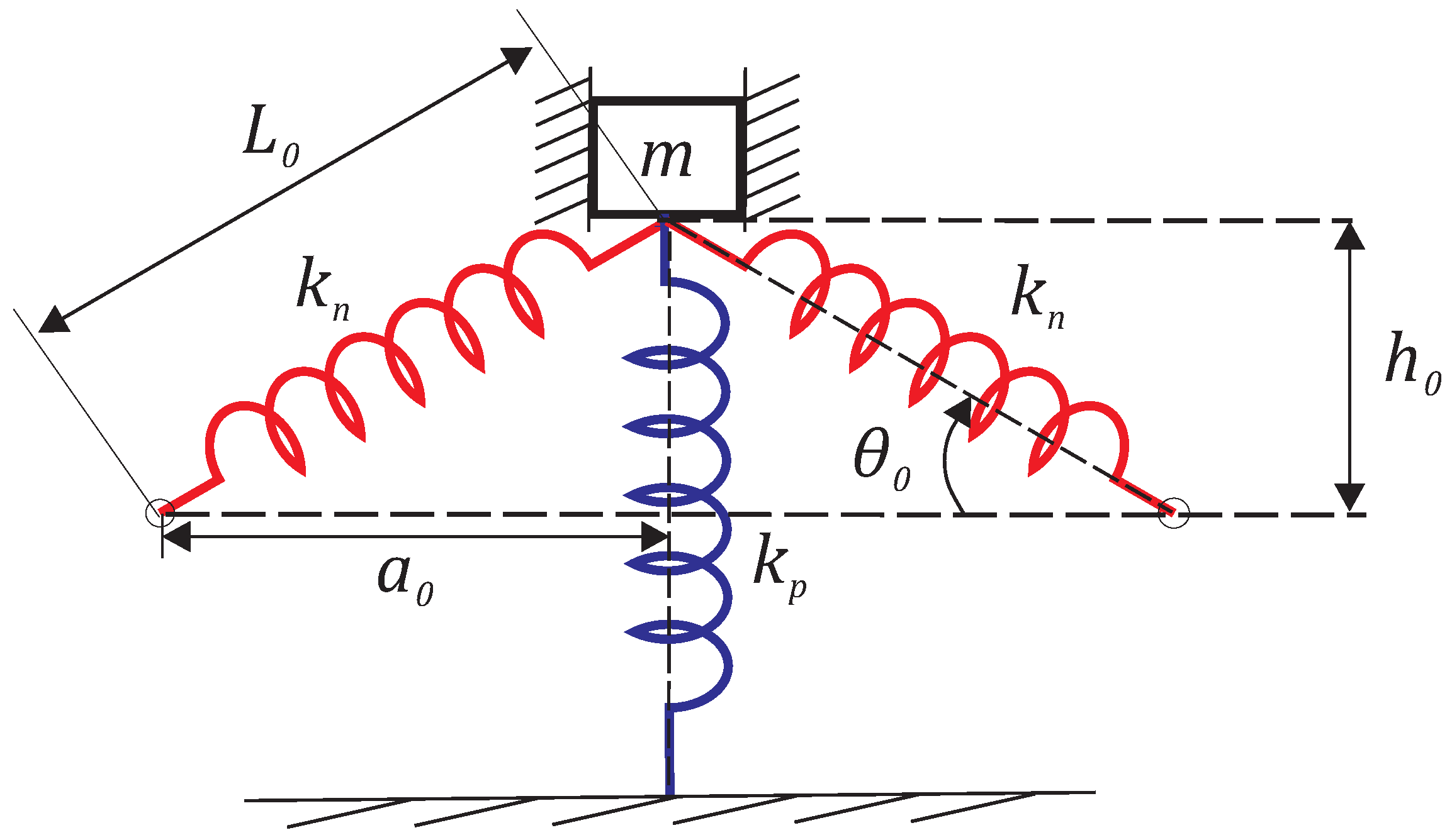
Figure 1 shows a schematic sketch of one of the famous QZS systems, which consists of one vertical spring (
), and two oblique springs (
) that are inclined at a predetermined angle (
) from equilibrium position (the QZS is in its originally undeformed position).
Figure 1 shows the QZS system at rest mode in its simplest form. However, such a design is vulnerable to many factors that may affect the range of stability around zero stiffness. These factors can be simply summarized in the geometrical factors and the stiffness ratio. The geometrical factors are the length of each spring (the oblique and vertical springs) and the inclination angle of the oblique springs. Putting all of these factors together helps in determining the distance between the suspension point of the oblique spring and the line of action of the vertical spring.
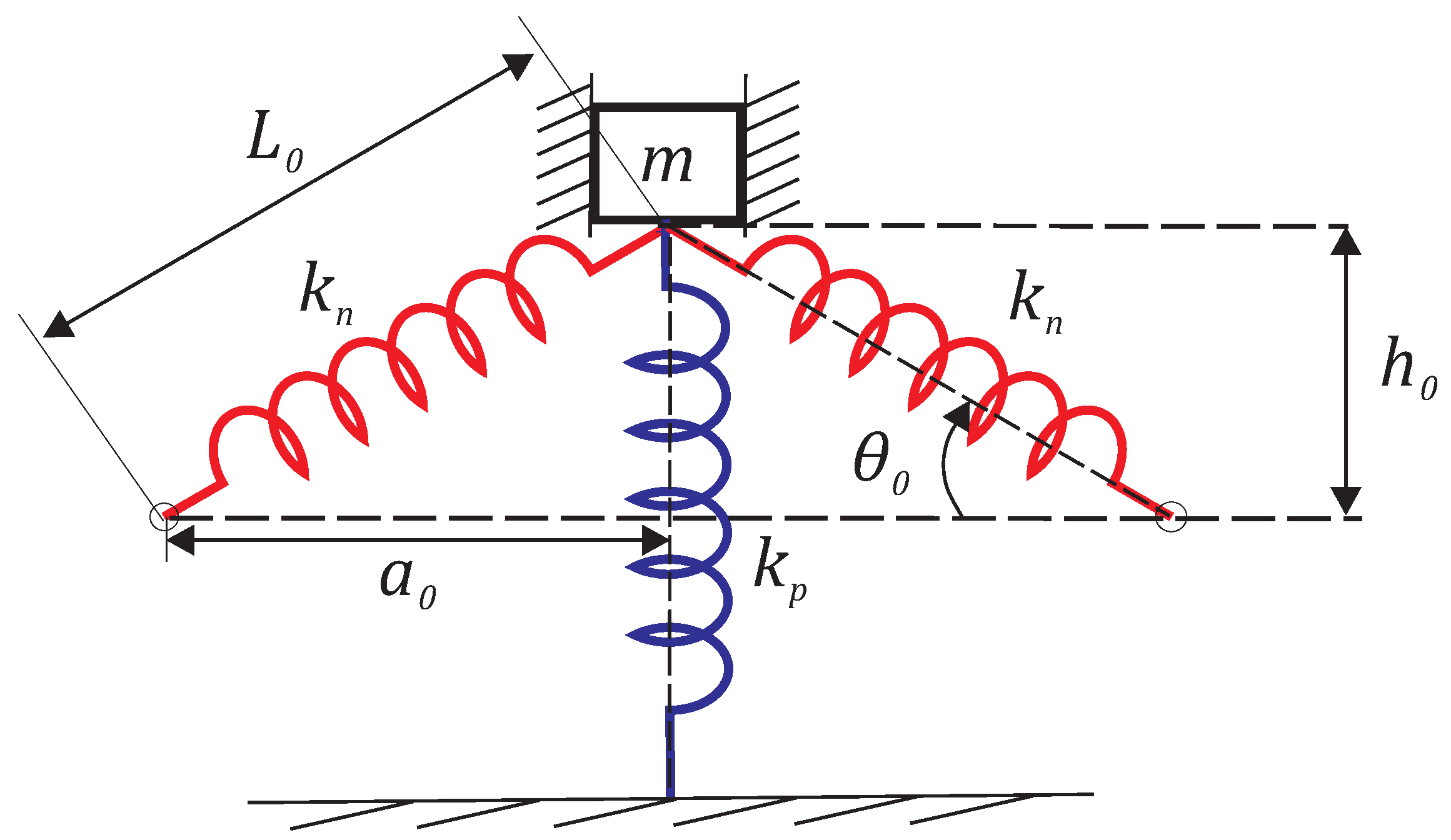
To achieve better control of the zero stiffness, it is advised to adjust the location of the horizontal deflection component for the oblique spring
with the help of either a manual adjuster or linear actuator, which is fitted at the suspension point of the oblique springs, as shown in
Figure 2.
The factors that affect the range of stability of the QZS system are expressed as follows: geometric ratio and the stiffness ratio .
3. Design Method for the Vibration Isolation System
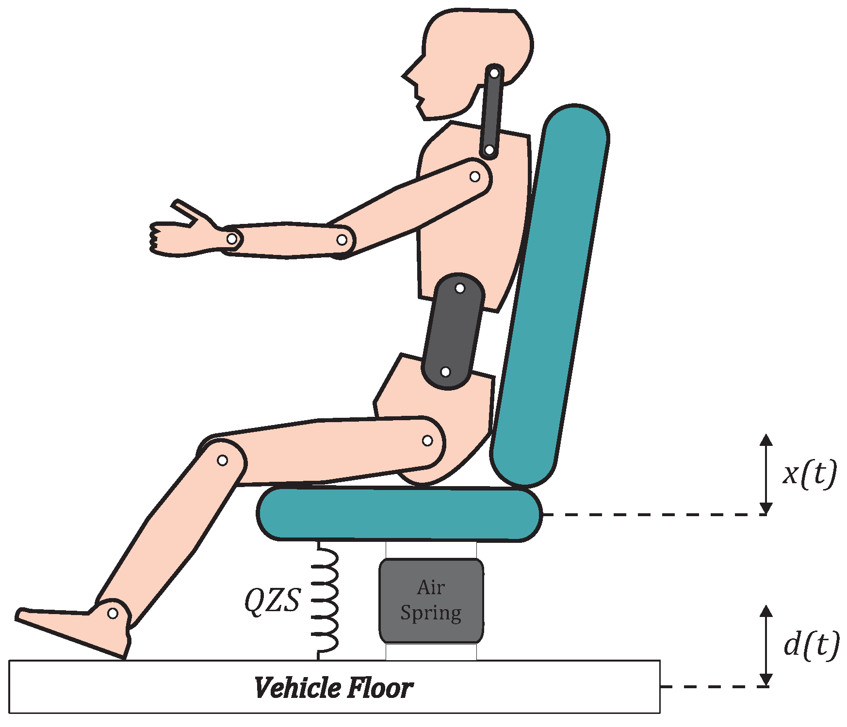
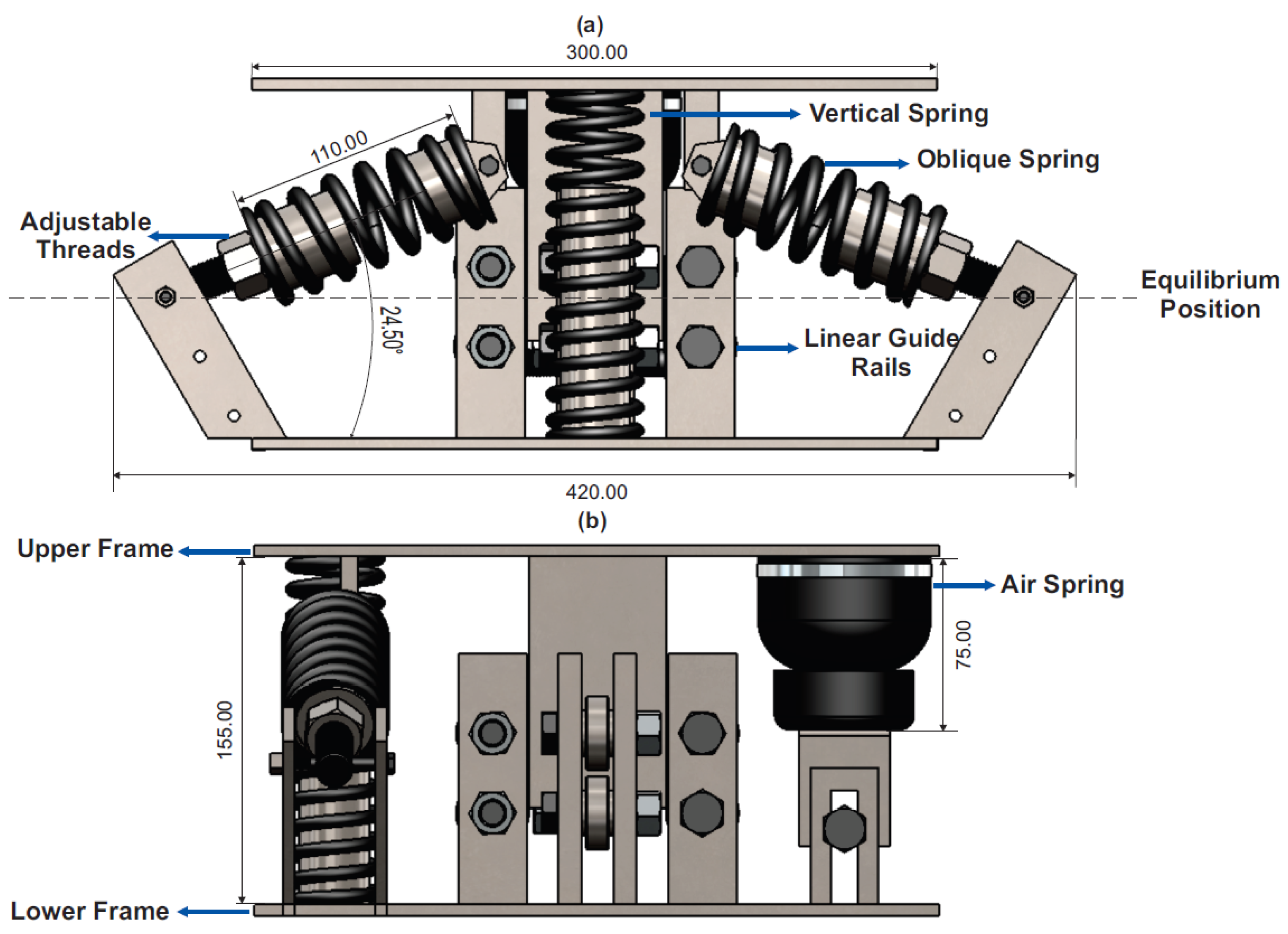
The aim of this study is to design a compact system that fits beneath the seat of the driver to isolate harmful low frequency vibrations that are transmitted to the driver’s body. The uniqueness of the proposed solution is the usage of a QZS system modified with an air spring.
Figure 3 illustrates the proposed system schematic and it also shows that the source of vibration on the seat
is the motion of the base, which happens due to the irregularity of the road profile
.
The equation of motion for the system shown in
Figure 3 can be expressed as
where
c is the damping coefficient, and
is the system spring force, given by
where
and
are the free length of the oblique spring and horizontal distance, respectively. Equation (
8) represents the approximated form of the force summation. The approximation is done using Taylor series expansion, as will be discussed in
Section 3.1.
As mentioned earlier,
is considered to be a harmonic function, given by
Equations (
8) and (
9) can be used to rewrite the equation of motion as
where
is the damping ratio, and the natural frequency of the system is expressed in the following form:
Hence, the natural frequency is variable due to the nature non-linearity of the system.
3.1. Static Analysis of the QZS System
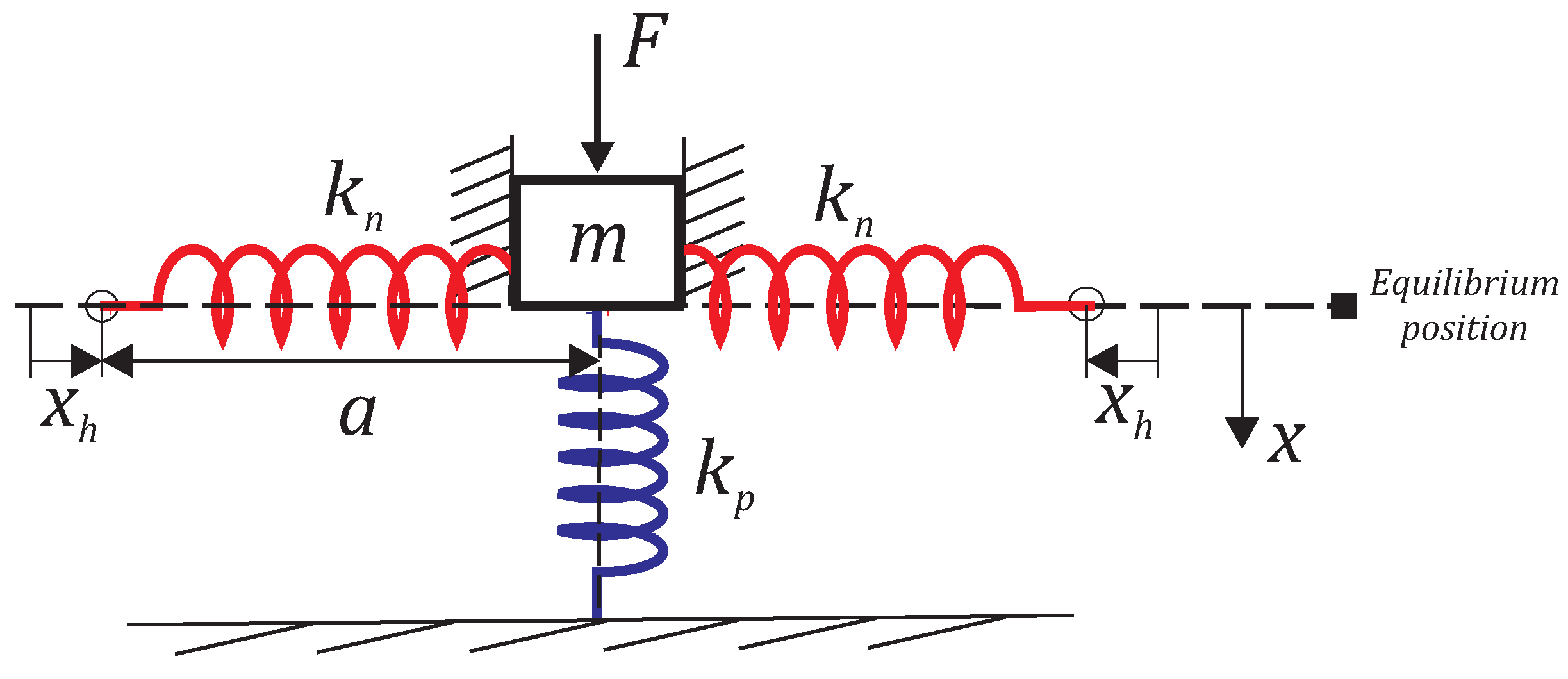
The aim of the following analysis is to set the equilibrium position and to determine when the equivalent stiffness of the system is equal to zero. The equilibrium position is determined when the angle of inclination for the oblique springs is equal to zero. At this equilibrium position and under a compression force acting on the slider mass (
m), the vertical spring and the two oblique springs are compressed, as shown in
Figure 4.
It is found that the summation of the forces acting on block
m is
where
, and
is the air-spring stiffness. It is worth noting that, in the situation where the applied force can be handled by the vertical spring alone, no air is delivered to the air spring and thus the vertical stiffness approximately equals
(see
Section 3.2 and
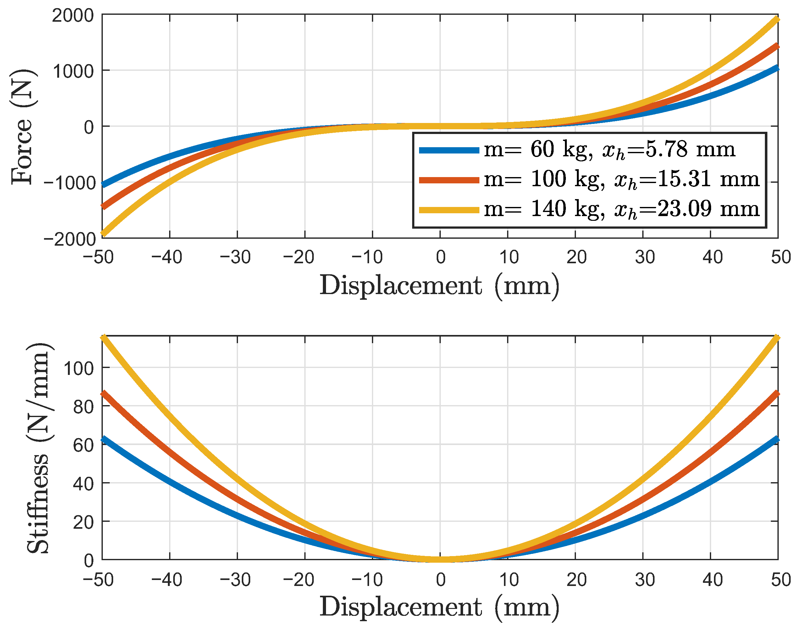
Section 4.1 for more details). Conversely, when the force exceeds what the vertical spring can withstand to maintain equilibrium, this over-weight can be supported by the air spring, but at the expense of an increase in the stiffness. However, this poses no problem thanks to the presence of a horizontal-adjustment mechanism that can negate this situation by keeping the geometrical ratio and stiffness ratio equal.
At the equilibrium position,
, Equation (
12) reduces to
The equation below describes the equivalent stiffness of the system and is obtained by taking the derivative of the force
F with respect to the deflection
x, as follows:
Now, to determine the situation where the stiffness equals zero, simply substitute
and
in Equation (
14). Hence, zero stiffness is achieved when the geometric ratio and the stiffness ratio are the same:
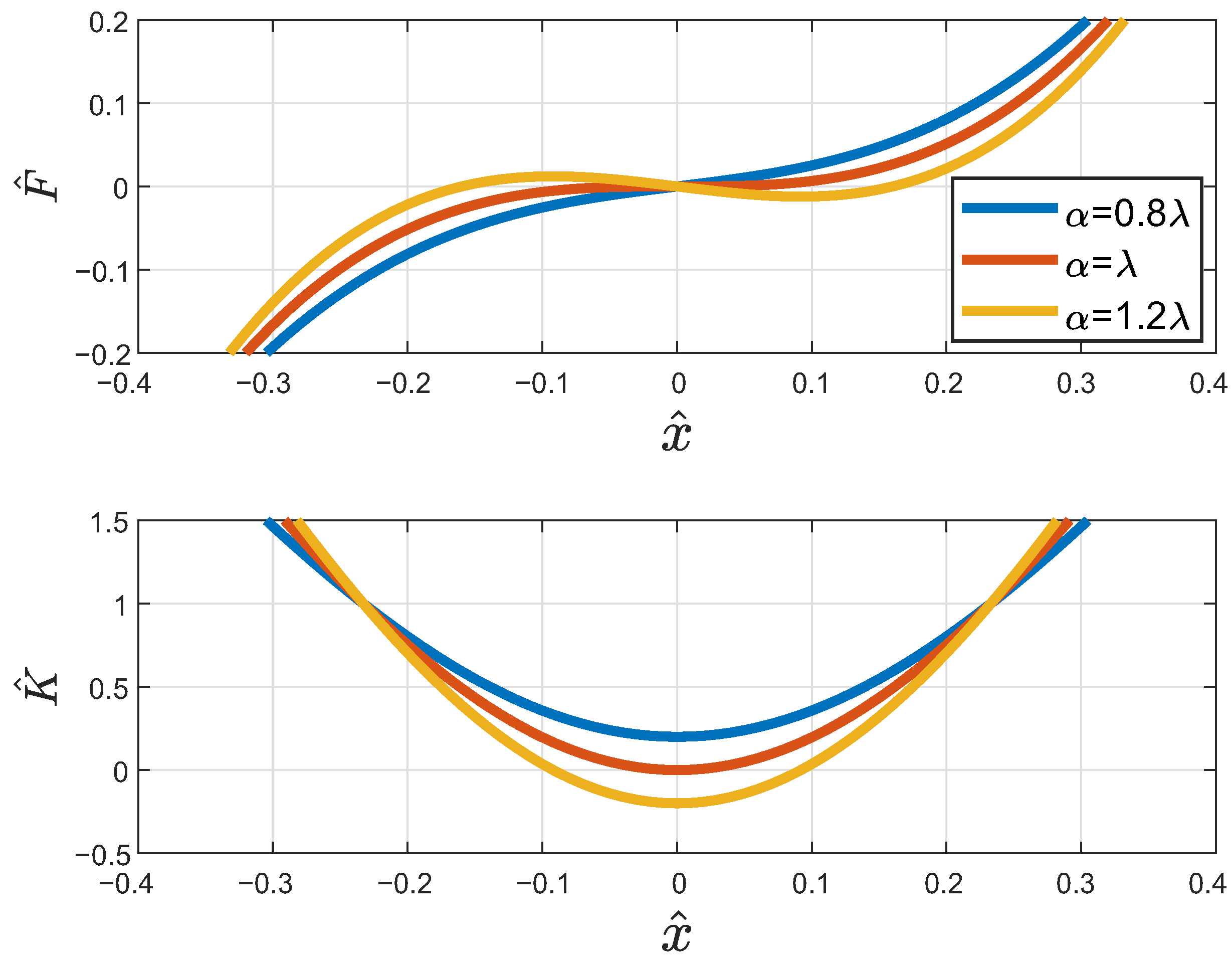
To study the factors affecting the range of stability, it is easier to shape a number of dimensionless parameters, which contain a wide range of factors in one single parameter. Hence, the following dimensionless parameters are used:
and
In addition, the geometric and stiffness ratios are expressed in the dimensionless form, as follows:
Based on this,
Figure 5 can be now obtained by changing the values of the factors that affect the stiffness of the system at different ratios between the geometry and the stiffness. As expected, the best range is achieved when the geometric ratio was equal to the stiffness ratio.
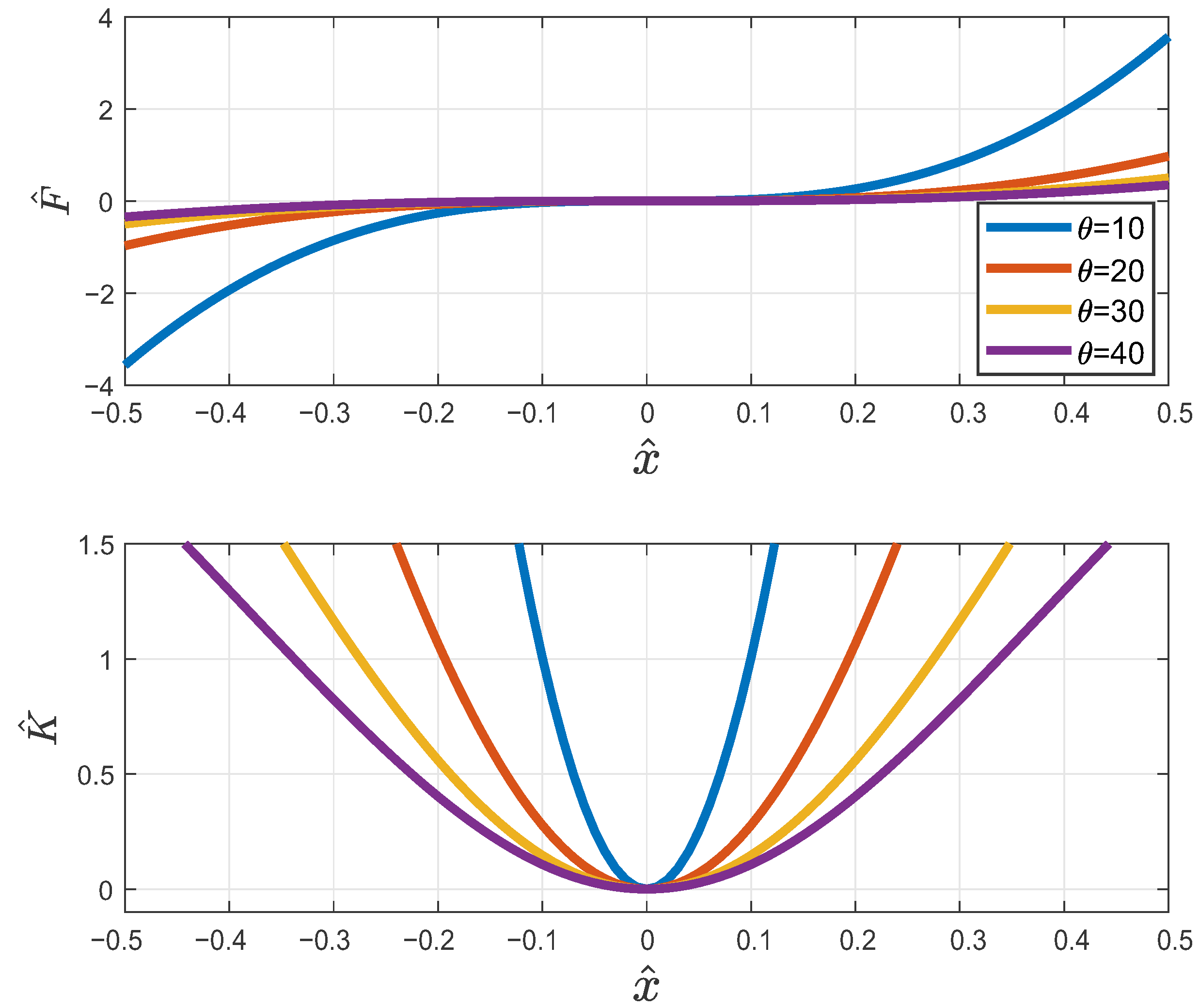
Results shown in
Figure 5 lead to defining the best angle of inclination for the oblique springs that achieves the best range of stability (see
Figure 6).
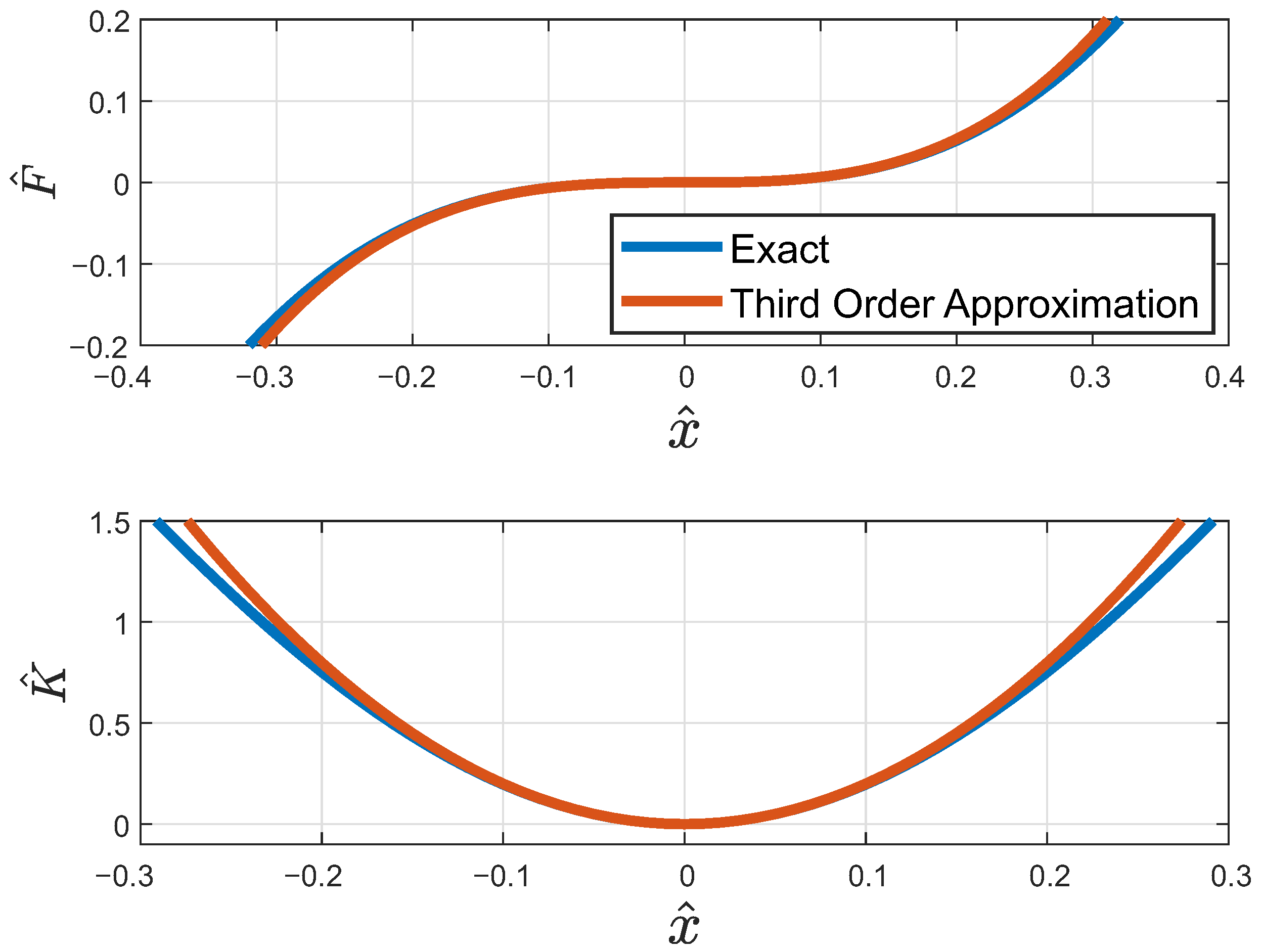
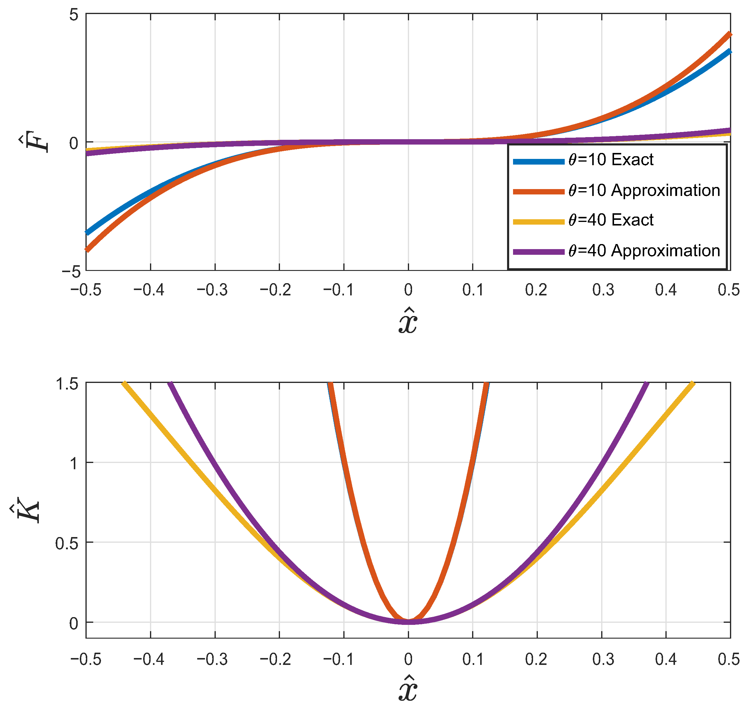
The next step is to find a good approximated representation of the force and stiffness equation. Therefore, a third-order Taylor series is used, as follows:
When the geometric and stiffness ratios are equal, Equation (
19) can be reduced as follows:
By taking the derivative of the above equation with respect to
, the dimensionless stiffness parameter may be expressed as
Figure 7 and
Figure 8 show that the exact and the approximated solutions are approximately the same, and thus can be used for the analysis discussed in
Section 4.
3.2. Air Spring
This newly modified QZS system becomes very essential because the weight of the driver is not fixed when the driver sits on the seat, which in turn affects the inclination angle of of the oblique springs in the QZS system.
Therefore, the proposed solution for this problem is to introduce an air spring, which can deal with the mass of the driver by inflating or deflating the air spring. In addition, this will help to control the initial position to be at the equilibrium, control the inclination angle of the oblique springs, and finally introduce an adequate amount of damping, which also helps in reducing the force transmitted to the driver.
Remark 1. Although air spring introduces another stiffness element in the vertical direction, which leads to higher natural frequency and hence less isolation, this amount of stiffness is already present in the vertical spring. Thus, the two systems (the air spring and the vertical spring of the QZS system) will share the same amount of stiffness instead of having a single system, i.e,. nothing has changed in terms of the overall vertical stiffness.
Remark 2. It is worth noting that introducing a damper instead of the air spring is not a good solution because obviously having a high amount of damping means losing the opportunity to isolate the system at large frequency ratios. In contrast, the air spring introduces a very small amount of damping and it marginally affects the overall isolation, but majorly isolates the force from being transmitted to the driver.
In summary, the presence of the air spring is indeed one of the main pillars that this system stands on. It gives the advantage of supporting a variety of loads while keeping the system at the equilibrium position for different types and values of the load. Thus, it achieves the optimum isolation performance without introducing high damping into the system.
5. Conclusions
This study has focused on isolating harmful low-frequency vibrations that are transmitted to the vehicle’s seat. The solution is based on lowering the natural frequency of the system by introducing an isolation system with low or zero dynamic stiffness, and thus, the frequency range of isolation will be increased.
The practical implementation for the proposed vibration isolation system is based on implementing a simple and compact system that combines the merits of the QZS with an air spring, which is able to isolate extremely low levels of vibrations. Herein, the novelty of the proposed system is (i) its capability of isolating the unpredictable roadway low-level disturbances and (ii) its compatibility with B-segment and C-segment cars, which are considered important factors for the future of passenger car production.
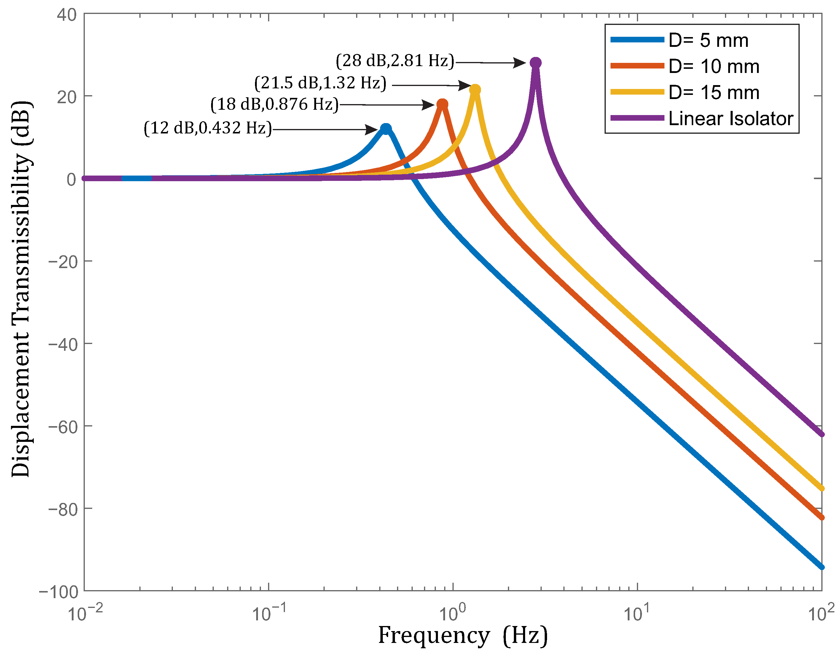
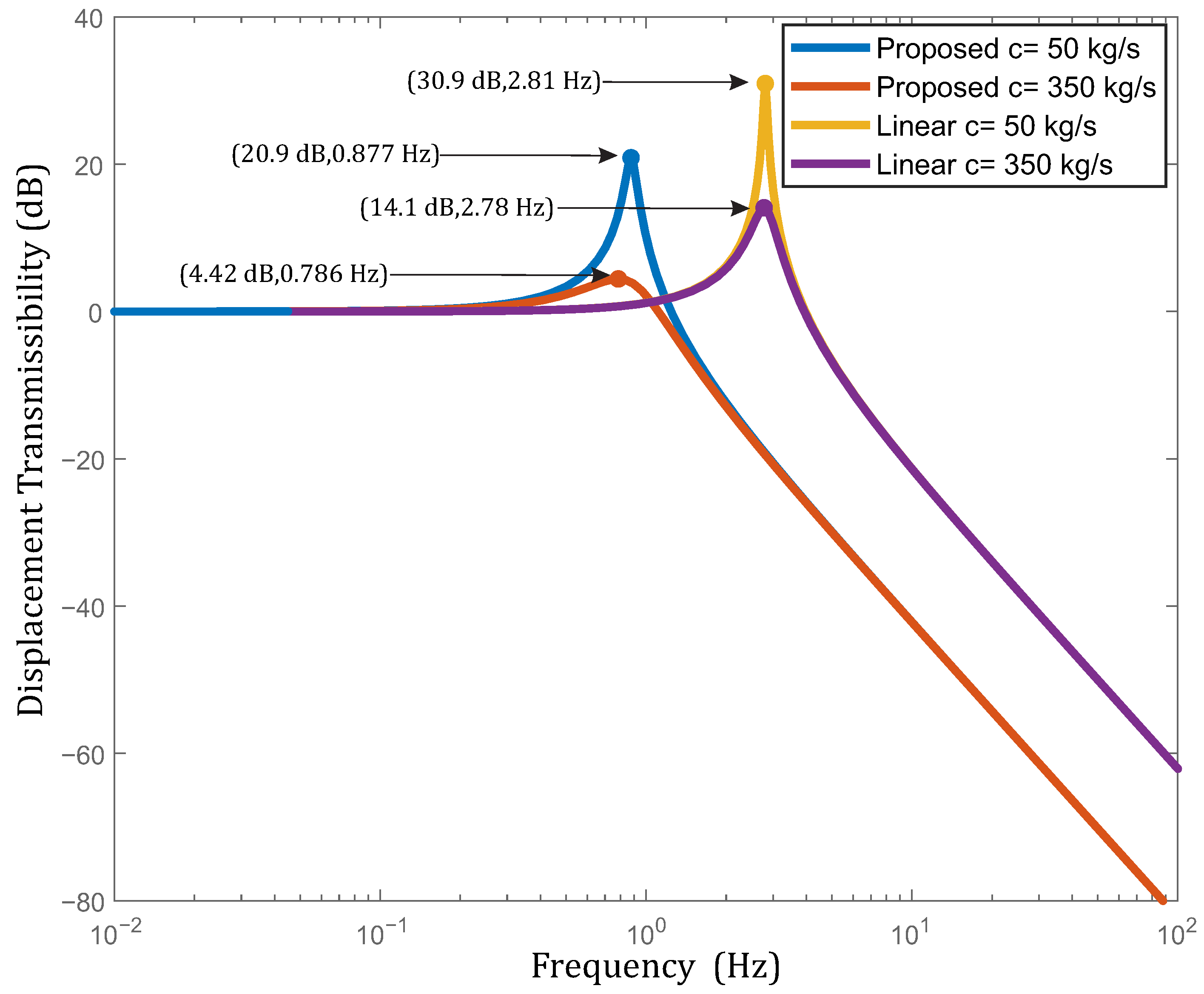
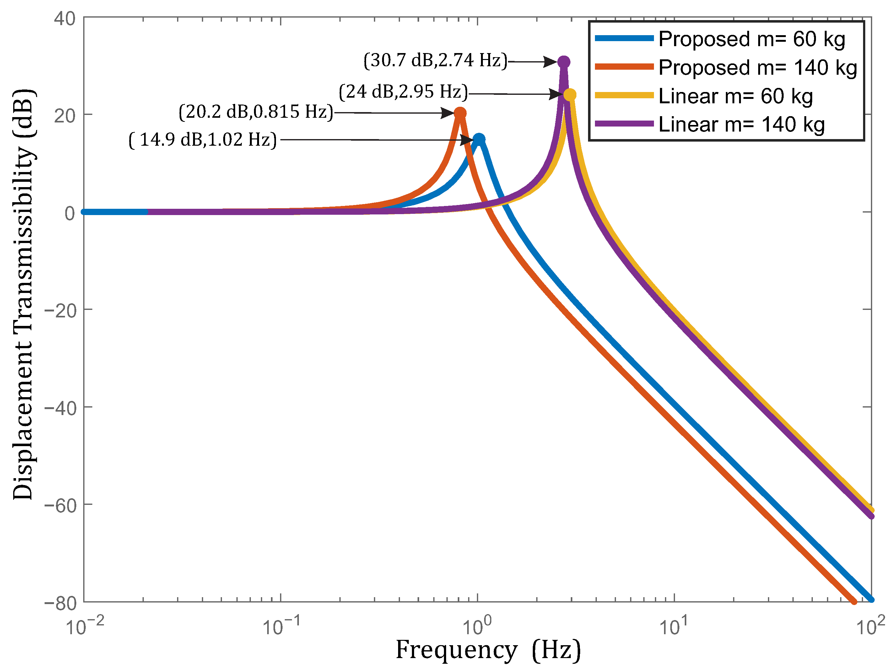
Parametric analyses were performed to prove the efficiency of the proposed system in terms of the displacement transmissibility (a pointer of efficiency). Displacement transmissibility was tested under different amplitudes of excitation, different driver loads, and different damping coefficients. For each test, a comparison was generated between the proposed system and an equivalent linear mass-spring-damper system. The results have revealed that the proposed system was very efficient and better than the equivalent linear system under all circumstances. It was also observed that the proposed system provides lower peak transmissibility and a broader range of frequency isolation. More specifically, the proposed system was able to isolate vibrations at very low frequencies of excitation down to 0.65 Hz. Thus, for different conditions of excitation amplitudes and driver loads, the range of frequency of isolation was still suitable at less than 1.85 Hz.
Future research efforts will be dedicated to the implementation of the proposed system to perform experimental tests to verify the system performance compared with the simulation results. Finally, further studies are required to explore the effects of the air spring pressure, airflow, inflation, and deflation control for the isolator efficiency.


 ,
, 


