Article

Passive Thermal Control Design Methods, Analysis, Comparison, and Evaluation for Micro and Nanosatellites Carrying Infrared Imager

by
Shanmugasundaram Selvadurai
1,*,
Amal Chandran
1,2,
David Valentini
3 and
Bret Lamprecht
2
1
Satellite Research Centre, School of Electrical and Electronics Engineering, Nanyang Technological University, Singapore 639798, Singapore
2
Laboratory for Atmospheric and Space Physics, University of Colorado, Boulder, CO 80309, USA
3
Thales Alenia Space, 06150 Cannes, France
*
Author to whom correspondence should be addressed.
Submission received: 6 February 2022 / Revised: 7 March 2022 / Accepted: 8 March 2022 / Published: 10 March 2022
(This article belongs to the Special Issue Small Satellites Missions and Applications)

Abstract

:
Advancements in satellite technologies are increasing the power density of electronics and payloads. When the power consumption increases within a limited volume, waste heat generation also increases and this necessitates a proper and efficient thermal management system. Mostly, micro and nanosatellites use passive thermal control methods because of the low cost, no additional power requirement, ease of implementation, and better thermal performance. Passive methods lack the ability to meet certain thermal requirements on larger and smaller satellite platforms. This work numerically studies the performance of some of the passive thermal control techniques such as thermal straps, surface coatings, multi-layer insulation (MLI), and radiators for a 6U small satellite configuration carrying a mid-wave infrared (MWIR) payload whose temperature needs to be cooled down to 100K. Infrared (IR) imagers require low temperature, and the level of cooling is entirely dependent on the infrared wavelengths. These instruments are used for various applications including Earth observations, defence, and imaging at IR wavelengths. To achieve these low temperatures on such instruments, a micro-cryocooler is considered in this study. Most of the higher heat dissipating elements in the satellite are mounted to a heat exchanger plate, which is thermally coupled to an external radiator using thermal straps and heat pipes. The effects of the radiator size, orbital inclinations, space environments, satellite attitude with respect to the sun, and surface coatings are discussed elaborately for a 6U satellite configuration.

1. Introduction

Satellite thermal control methods that are currently used by conventional space missions are well established and proven. The term “NewSpace” is being adopted by many agencies and industries in recent days. According to experts, NewSpace is an approach focused on lowering the barriers of entry into space, by providing cheaper access to space and by commercializing the space sectors [1]. This has also further increased the interests among many small satellite manufacturers, research organizations, universities, and start-ups to build complex missions at a lower cost using nanosatellites and CubeSat platforms, especially for technology demonstration, science, research, educational projects, and commercial applications [2]. These nanosatellites typically weigh 1 to 10 kg and follow CubeSat size standards where 1U is a 10 × 10 × 10 cm 3 cube. There are other challenges in the new era of space technologies but this article focuses only on thermal management challenges on small satellites. Due to miniaturized electronics, high power components, and payloads, the satellite becomes heavily packed within the smaller satellite volume, and this leads to thermal problems as the available radiative surface area is reduced [3,4]. There is a necessity to solve thermal challenges for high power, scientific, and cryogenic small satellite missions. Taking advantage of small satellites, earth exploration missions are now being carried out using nano/microsatellites and are expected to grow exponentially [5,6,7]. Earth observation (EO) refers to the use of remote sensing technologies to monitor land, marine and atmosphere. Most of the earth observations are done in the infrared region of the electromagnetic spectrum. Infrared detectors that are designed to operate in the wavelength ranging from 0.76 μm to 103 μm need to be cooled down for better performance. The relationship between infrared wavelength and temperature is defined by Wien’s displacement law in Equation (1) as follows,
λ T = b
where, b is Wien’s constant (2898 μmK), λ—Detection wavelength, and T—Low temperature. From this relation, it is clear that the radiation wavelength shifts toward the shortwave direction as the temperature rises. In general, the longer the infrared wavelength is, the lower the operating temperature of the detector will be [8].
Infrared detectors operating at a non-zero temperature are subjected to dark current (DC) noise which is directly related to pixel area, detector material properties and detector temperature. DC noise is the dominant limitation in many detectors and a relationship to calculate the DC is given in Equation (2) [9].
I D C = C × T 2 × A d × e Δ Q k T d
where, I D C —Dark Current intensity (A); C = Constant (1.2 × 10 6 A·m−2·K−2); T d —Pixel Temperature (K); Δ Q —Energy band gap (eV); A d —Pixel area (m 2 ); Q—Electron charge (−1.6022 × 10 19 J); k—Boltzmann constant (1.38064852 × 10 23 J/K); T—Detector temperature (K).
Dark current is significantly reduced when operating at lower temperatures, and hence most of the infrared detectors are required to be cooled to lower temperatures for certain applications. The low temperature requirement becomes of utmost importance for the detectors operating at the cryogenic temperature regime [8]. This study considers a mid-wave infrared (MWIR) instrument whose detector is required to be maintained between 0 to −100 °C for a few specific mission operations. Traditional passive thermal control methods are studied both numerically and analytically to analyze the effectiveness of the overall thermal control system in maintaining the payloads and components at required temperature levels.
For missions with such infrared (IR) payloads and stringent thermal requirements, active thermal control systems are used. Satellite active thermal control systems (ATCS) rely on input power for operation and have been shown more effective in maintaining the required temperature within required limits [10] but this increases the total power budget of the satellite and eventually the cost. In general, small satellites cannot generate more power due to limited solar array size. Some of the active thermal systems are thermo electric coolers, electric heaters, and pumped fluid loop systems. Besides cost and input power, these methods require additional volume which is limited in small satellites. Unlike active systems, a passive thermal control system (PTCS) does not require any additional input power from the satellite and it also can be implemented at lower cost. Some of the passive thermal control systems are, multi-layer insulation (MLI), thermal straps, radiators, thermal louvers, heat pipes, phase change materials, and thermal switches [11]. No small satellite missions with thermally sensitive IR instruments (operating at cryogenic range of temperatures) have flown and it is only due to lack of thermal control systems. NASA’s JPL has developed an active cryocubesat (ACCS) [12] for such a thermally sensitive IR instrument, which is a breakthrough technology for many future cryogenic small satellite missions. To save cost, power, and volume inside the satellite, a few PTCS are studied for a nano/micro satellite carrying a an IR instrument.

2. Satellite and Payload Considered

Technological advancements and miniaturization have led to the use of infrared (IR) instruments in nanosatellite platforms [13]. Infrared instruments used for space imaging, Earth observation (EO), astronomy, surveillance, and hyper- spectral remote sensing at higher IR wavelengths come with thermally sensitive detectors, and these detectors are to be operated in a controlled temperature environment for better performance [14].
Table 1 lists all of the instruments in different IR wavelength categories and their detector temperature requirements. Cooled detectors are proven to have higher sensitivity with an extremely reduced signal-to-noise ratio [15]. In some literature, the term thermal infrared (TIR) is used and it is a combined form of both MWIR and SWIR.
Figure 1 shows how the heat flows from each element of the system to a deep space radiator. Passive thermal control methods analyzed in this study are mainly for MWIR detector’s thermal requirement and other mission requirements. For this payload as seen in Figure 1, it is assumed that the detector is lying inside the instrument and it is coupled to a micro-cryocooler through a high thermal conductivity strap. Heat generated from active micro-cryoccoler parts and associated electronics is carried away to radiator then radiated to space.
This study initially elaborates the theoretical background of the passive thermal control methods such as multi-layer insulation (MLI), thermal straps, radiators, heat pipes, and surface coatings. This is then supported with numerical analyses and performance evaluation studies carried out for a nanosatellite configuration.

3. Passive Thermal Control Methods

3.1. Multi-Layer Insulation

Thermal insulation is crucial for cryogenic and infrared satellite missions. Multi-layer insulation (MLI) blankets are the most efficient insulation material for space applications [18]. The MLI blanket is in general comprised of a number of low-emittance sheets combined with low-conduction netting layers to control the heat transfer for low temperature applications such as cryogenic instruments. Thermal insulation performance is quantified as effective emissivity (e) and is dependent on the number of inner layers as well as geometric considerations (number of bends, holes, etc.). Effective emissivity is defined as in Equation (3) [19]
e = Q T o t a l σ ( T h o t 4 T c o l d 4 )
where, e—Effective emissivity; Q—Total incoming heat flux (W/m 2 ); σ —Stefan-Boltzmann constant (5.670374419 × 10 8 W/m2·K4); T h o t —Temperature of the MLI hot side (K); T c o l d —Temperature of the MLI cold side (K). Typical values for e are closer to in the range 0.0150 to 0.03 [19].
MLI in satellites is widely used for the following reasons [20].
  • To prevent excessive thermal flux from/to various satellite components
  • To minimize thermal gradients through out the components
  • To reduce temperature variations due to change in orbital environment conditions.
Thermal conduction across the thickness of the MLI is very sensitive to the layer compression. To minimize the MLI conduction heat transfer, any compressive pressure or bending of blankets must be avoided [19]. This conduction term is defined as the total temperature difference ( Δ T ) between the outer blanket layer and the inner blanket layer divided by the total number of layers. Assuming that the temperature distribution is uniform throughout the blankets, the conduction heat transfer per unit area is given by Equation (4) [21]. MLI efficiency reduces as the size decreases because heat transfer at the blanket edges increases and hence MLI generally does not perform well on small satellite platforms [10].
q c = k c Δ T n
where, q c —MLI conduction heat load per unit area (W/m 2 ), k c —Conductance of a single MLI layer (W/m 2 K ), Δ T —Temperature difference across the MLI layer (K), n—Number of MLI layers. Heat flux due to conduction can be reduced by increasing the number of inner layers and this reduction is linear with increasing layer numbers. Conductive heat transfer is typically negligible and ignored in MLI blankets. Unlike conductive heat transfer, radiation heat transfer is considered and is given in Equation (5) [21].
q r = 2.835 × 10 5 ϵ T h o t 4 T c o l d 4 n
q r —MLI radiative heat flux (W/m 2 ), ϵ —Emissivity of MLI outer layers, T h o t —Temperature of the MLI hot side (K), T c o l d —Temperature of the MLI cold side (K), n—Number of MLI layers. From both conduction and radiation terms, it can be proven that the total heat flux is minimized when the number of MLI layers are increased.

3.2. Surface Paints

The satellite’s passive thermal control system mainly uses specially prepared thermal coatings to maintain the subsystem temperature within safe operating ranges. In space, external satellite surface paints or coatings are greatly influenced by adverse environmental effects, namely, Atomic Oxygen (ATOX), molecular contamination, and Ultraviolet radiation (UV) [22]. Energy absorbed by the satellite surfaces depends on the external surface characteristics and area. The major concern in using paints is the degradation of physical and thermo-optical properties of the components and this degradation is dependent on mission duration and orbit altitude. Thermal radiation heat transfer on satellites can be controlled using materials that have specific thermo-optical surface properties, which are solar absorptivity ( α ) and infrared emissivity ( ϵ ). These properties are dependent on materials and processing techniques [23,24]. α governs how much solar incident heating a spacecraft absorbs, while ϵ determines how much heat a spacecraft emits to space [10]. By altering α and ϵ , the overall temperature of the spacecraft can be controlled to some extent. There are numerous space qualified paints and coatings that are commercially available and most of them have space heritage. Radiative tapes also provide better performance. For example, second-surface fluorinated ethylyne propylene (FEP) provides better performance as radiator coatings [10] and for most small satellites, adhesive tapes or surfaces finishes (polishing, anodize, alodine) have been considered. End-of-life (EOL) properties are considered in the early design phase as the absorbed solar energy will gradually increase over the years due to degradation of surface properties. In general, satellite components will run cooler in the early phase of the mission life and additional heaters may be used to avoid temperature drops for the critical components [25].

3.3. Thermal Straps

Thermal straps are excellent passive heat transfer devices that are commonly used on space missions to conduct the heat from inaccessible regions of the spacecraft and radiate into space. Thermal straps come in various shapes and lengths according to the requirement. They are comprised of thin wires of high thermal conductivity metals or foils which make them flexible and efficient thermal links. Thermal straps are made of different metals and some of them are listed in Table 2 with their thermal properties.
Thermal contact conductance (TCC) is a property of heat conduction between solid bodies in thermal contact. This property is highly dependent on contact pressure and surface flatness. TCC influences the overall performance of the thermal strap and the relationship is given in Equation (7) [26].
Q s t r a p = λ A l Δ T
C = Q s t r a p Δ T = Q h t r Q l e a k Δ T = Q h t r Q r a d Q h t r l e a d s Q T C l e a d s Δ T
where, λ —Thermal conductivity (W/mK), A and l are, respectively, the cross-section (m 2 ) and the length (m) of the heat path inside the medium, C—Thermal contact conductance ( W / K ), Q s t r a p —applied heat load into the thermal strap (W), Q h t r —heat load from the heater pad, Q l e a k —total heat lost from the heater pad due to radiation ( Q r a d ), from the heater wire leads ( Q h t r l e a d s ), and thermocouple leads ( Q T C l e a d s ). Δ T is the difference in temperature measured at the ends (°C). Variation in thermal strap conductance is shown in Figure 2. The lower the thermal strap conductance, the higher the difference in temperature between two ends of the thermal strap will be.

3.4. Thermal Straps Conductance Characterization

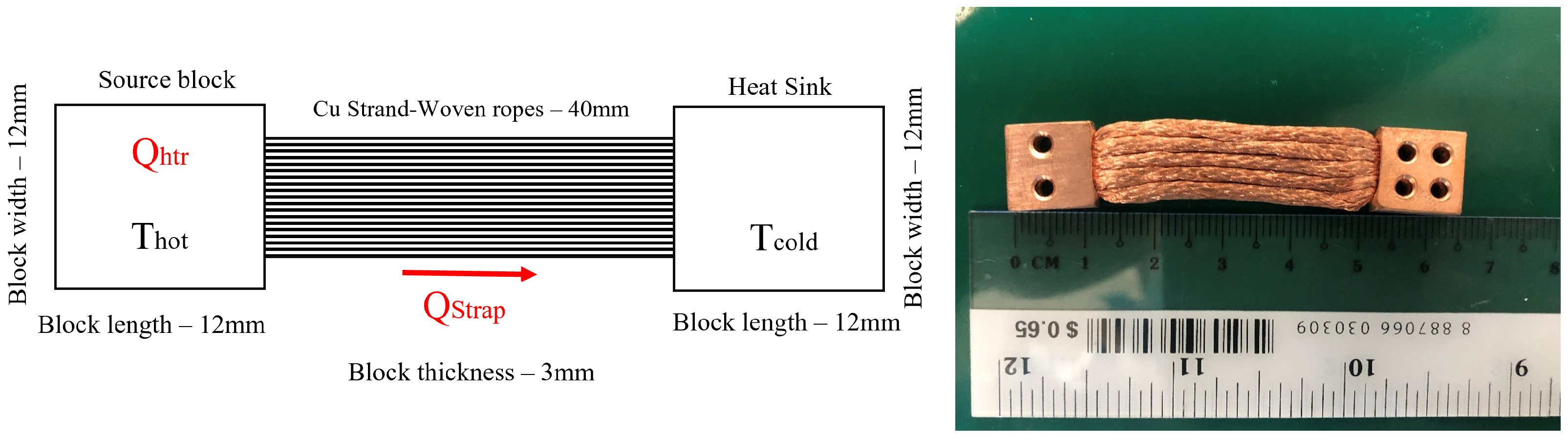
The test unit consists of a copper thermal strap of the dimensions as described in Figure 3, a thin polyimide heater pad, and two thermocouples for temperature measurement. The entire unit was kept inside the thermal vacuum chamber (TVAC) which contains a temperature-controlled high emissivity shroud and baseplate. The main idea of this test is to find out the thermal conductance of a custom made thermal strap. Prior to the actual test, a preliminary start-up test was performed at a vacuum condition, at 10 5 mbar, to analyze how conduction heat transfer plays a major role in transferring the heat from one end to another end. One end of the thermal strap was heated sufficiently using a thin polyimide heaterpad (from minco, HK6903) and a thermal interface material (TIM) is used between the heaterpad and the copper block to minimize the resistance as the entire unit is kept at complete vacuum condition where there is no medium. Two T-Type thermocouples were attached to both hot and cold ends of the thermal strap to measure the actual temperature. The custom designed flexible copper braid that is cold pressed at each of its ends into copper blocks is covered with MLI to block the heat from getting radiated out.
Incremental heat loads were applied using an external power supply to the hot end, and the cold end is connected to an another copper block (cold sink) to generate a thermal gradient across the strap. Temperatures were measured from both the ends of the strap. It is assumed that the radiation loss is negligible due to MLI and the entire test sample is thermally isolated from the TVAC’s baseplate (a bare printed circuit board and a PEEK sheet) using thermal insulators and thus conduction heat loss is also considered to be negligible.
In the test setup, hot and cold end blocks of the copper strap were exposed to the test chamber due to the fact that the radiation from the copper blocks is assumed to be negligible as the surface emissivity of bare copper is 0.02 [
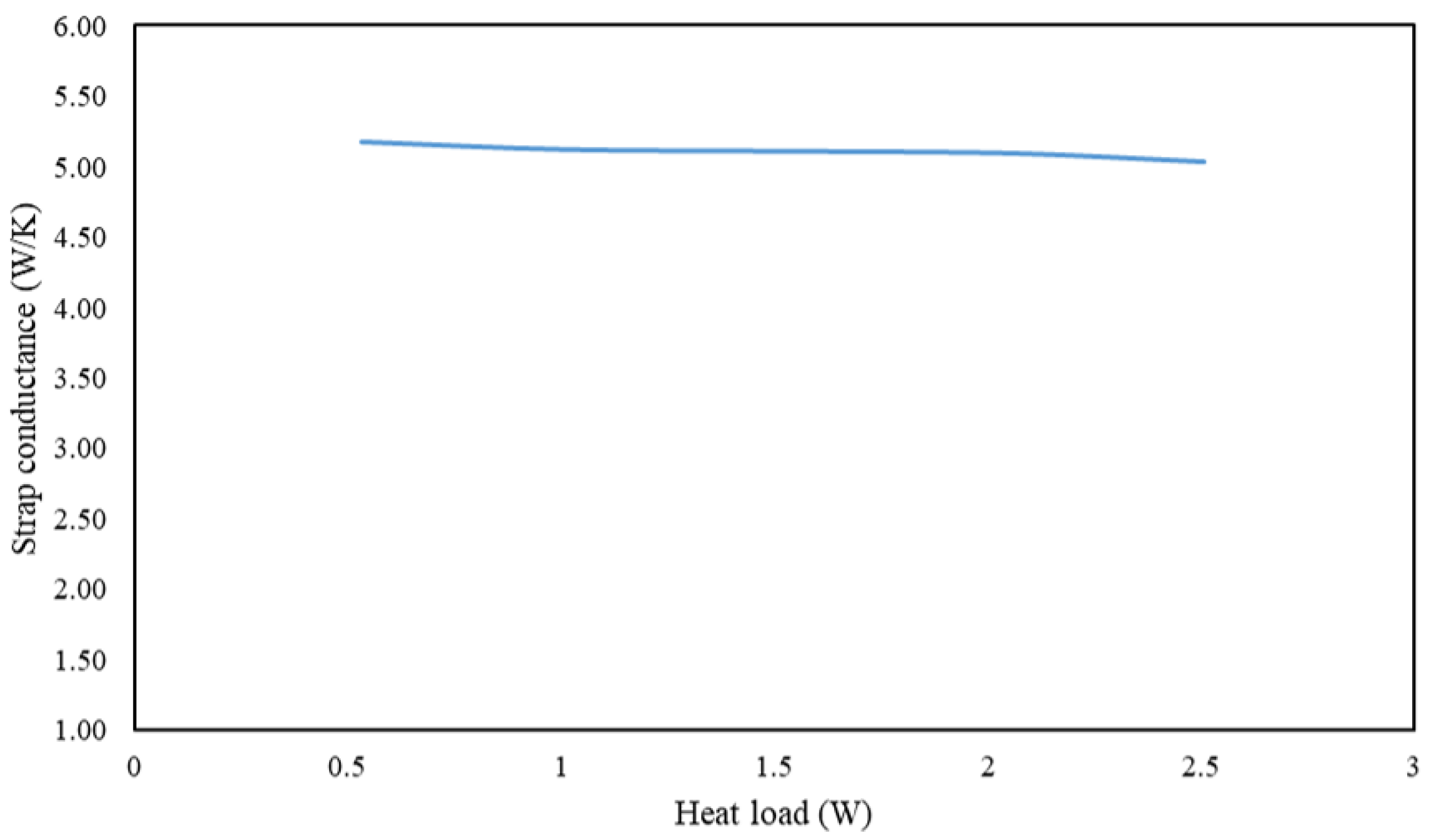
27]. However, other measurement uncertainties, such as TVAC system thermocouple reading uncertainties of <0.5 °C, and external power supply error of 0.005 percent, are taken care of and ensured to be within the minimum allowable limits. The stray heat leaks from the sources such as wire harnesses (no harnesses used), and PC104 connectors (a standard interboard connector with 104 metal pins for board-to-board communication and it is made up of black high temperature, glass filled nylon) are neglected in this analysis. When the heater was turned ON with 0.5 W initially, the temperature started to increase and then stabilized after approximately 50 min. Temperature readings after stabilization were recorded from both ends and the same sequence was followed for the rest of the incremental heat loads. For varying heat loads from 0.5 W to 3 W, hot and cold end temperature from the TVAC system were recorded and used to compute the thermal conductance using Equation (7) and plotted as shown in Figure 4. With increasing heat load, the temperature difference between hot and cold ends is increased, but the strap conductance of the strap remains close to a constant value. Temperature gradient ( Δ T ) for every incremental heat load ( Q s t r a p ) increases proportionally and this is the reason why the strap conductance is nearly constant. From the experiment, it is observed that the strap conductance varied between 5.17 W/K to 5.010 W/K for the given heat load, and thus an average value of 5 W/K is used for all the thermal simulations carried out in this study. This custom made thermal strap is expected to operate only under 3 W of heat load and hence, higher heat load (>5 W) test was considered to be unnecessary.

3.5. Passive Radiator

Radiators used on the spacecraft are passive radiating elements. In space, there is no medium present to convect or conduct away the waste heat from the spacecraft components to deep space, and it has to be lost only through radiative heat transfer. Radiator panels are specially designed for this purpose, and they come in various configurations such as single active face (Body-mount radiators, BMR) and double active face (deployable radiators, DR) [28,29]. Radiator design and its mounting location on the spacecraft body greatly influences the performances of the radiating panel. Most importantly, radiators are mounted in a location where external fluxes are minimized. Body-mount radiators are designed as an integral part of the spacecraft (S/C) or can be designed separately and mounted to the external surface of the S/C structural body [
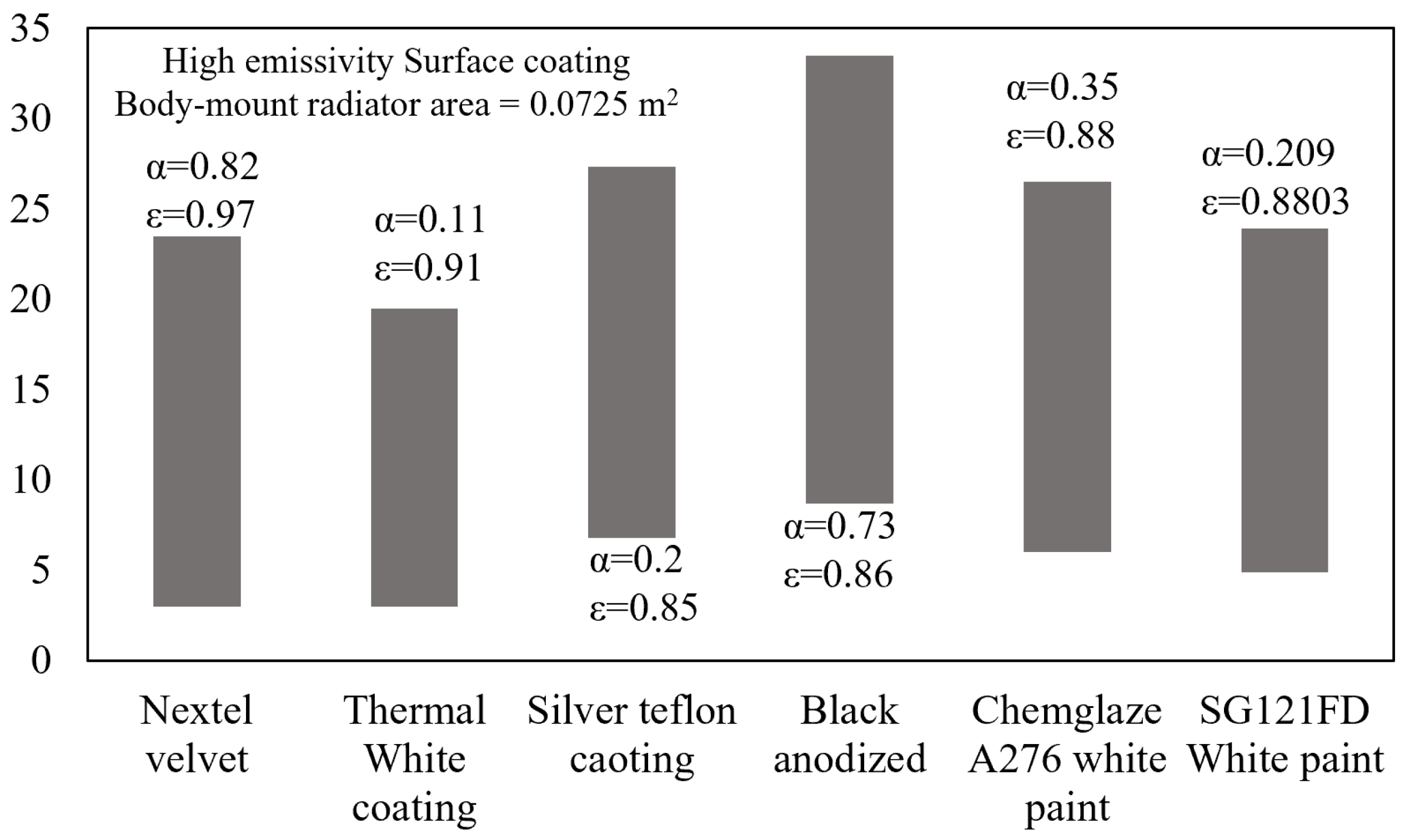
30]. Secondly, optical properties of the radiators are considered important as the radiating power is dependent on surface coating. Radiating power ( Q r a d ) of the radiator is defined by the Stefan-Boltzmann equation as in (8).
Q r a d = A R a d ϵ σ F v ( T r a d 4 T s 4 )
where, A R a d —Radiator surface area, ϵ —emissivity of the radiator surface, σ —Stefan Boltzmann constant (5.670374419 × 10 8 W/m2·K4), F v —view factor and it will normally be close to unity and it can be lower if the respective surface is partially occulted by other spacecraft components, T r a d —Temperature of the radiator surface and T s —deep space temperature (assumed 3 K). Q r a d is radiating power of the radiator and it is strongly dependent on the surface temperature.
Thermal equilibrium condition is defined as the total incoming heat ( Q i n ) equal to heat leaving ( Q o u t ) the system and it is given by Equation (9). The following governing equations are used for calculating the radiator area for any given environmental conditions [11,31].
Q i n = Q o u t
On comparing,
q s α A s cos ( θ ) = ϵ σ T 4 A
Steady state radiating surface temperature is computed by,
T = q s α cos ( θ ) ϵ σ 1 4
At LEO, a satellite’s thermal equilibrium condition is given by Equation (12),
Q I n t e r n a l + Q S o l a r + Q A l b e d o + Q I n f r a r e d = Q r a d
Radiator sizing depends on the total external heat load which is a sum of the solar flux ( Q S o l a r ), planet albedo ( Q A l b e d o ), planet IR flux ( Q I n f r a r e d ), and internal heat load ( Q I n t e r n a l ).
Equation (13) shows the heat balance between the radiator and the space environment in steady state.
( A s q s + A A q A ) α + A E q E ϵ + Q i n t e r n a l = A σ ϵ F v T r a d 4
Equation (13) can be further simplified as follows,
Q e x t e r n a l + Q i n t e r n a l = A σ ϵ F v T r a d 4
Alternatively,
q ˙ a b s o r b e d . A + Q i n t e r n a l = A σ ϵ F v T r a d 4
where, Q e x t e r n a l —Total external flux and it is a sum of Q s o l a r , Q A l b e d o , and Q I n f r a r e d . A s , A A and A E are the projected areas receiving, respectively, solar, albedo and planetary radiation. F v is the view factor from the radiator to the space environment (assumed perfect view into space, F v = 1) and A E is the projected area of the earth. q s , q a , and q E are solar flux, albedo flux, and earth IR flux, respectively. q ˙ a b s o r b e d is the total flux or heat absorbed from solar, albedo and infrared radiation per unit area.
Radiator area is calculated using Equation (16) [32],
A r a d = Q i n t e r n a l ϵ σ F v T r a d 4 q ˙ a b s o r b e d
And the surface temperature of the radiator is calculated using Equation (17).
T r a d = q s α cos ( θ ) + Q w A r σ ϵ 1 4
where α is absorptivity of the radiator surface, q s is the incident solar flux on the radiator panel, Q w is the heat to be rejected. By knowing Q i n t e r n a l and other environmental heat loads, radiator area can be calculated using Equation (16) assuming that the view factor is 1 for preliminary calculations. If the radiator design calculations are carried out for GEO satellites, Q a l b e d o and Q I R are generally ignored as the effect of earth’s albedo and IR flux are insignificant (approximately <0 [11]) because as the altitude increases, environmental loads from earth decreases rapidly. One exception to this is the case of cryogenic systems, which operate at very low temperatures that even small environmental heat loads from earth are significant to the thermal design [11].
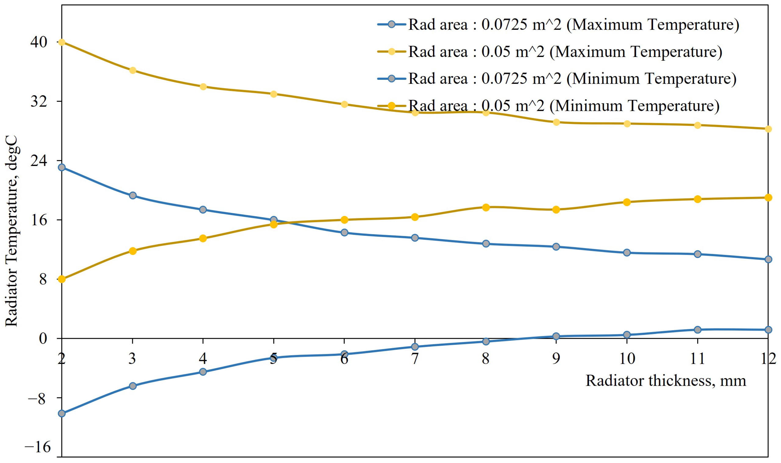
The radiator panel for the 6U satellite platform is optimized for two design parameters.
  • Radiator size: Radiator panel is allowed to vary in size for maximum radiating capacity. Length and width of the radiator are varied while keeping the thickness constant.
  • Radiator Thickness: Radiator thickness is varied while keeping the surface area constant.
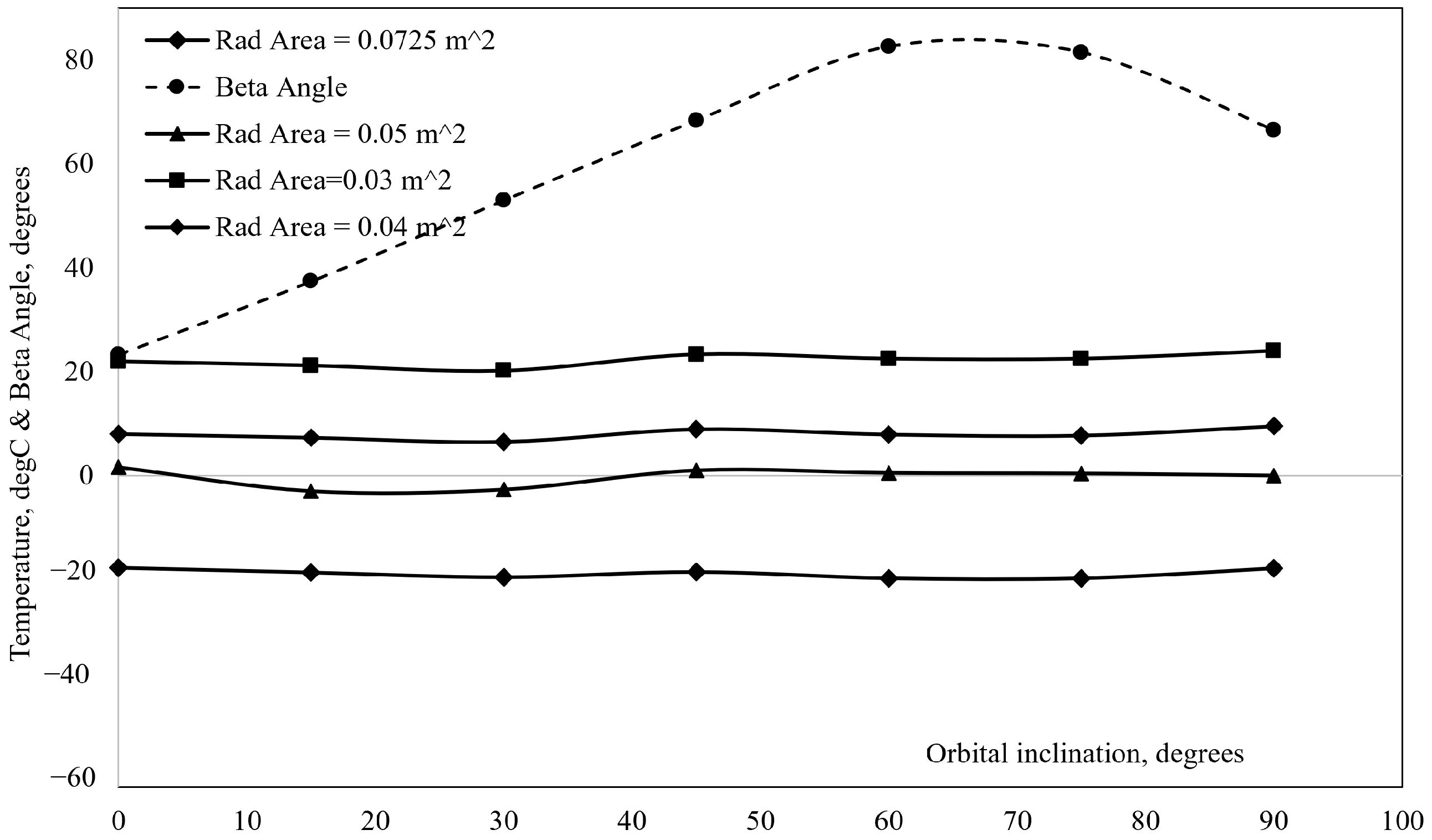
Radiating temperature of the radiator for both of these conditions are varied as the input heat load remains same. To account for varying orbital thermal loads, performance studies were carried out for two orbital worst-case conditions. A few assumptions made for this performance study were,
  • The radiator loses heat only by radiation mode of heat transfer
  • Calculations are done for steady state conditions with constant properties
  • Radiator temperature is assumed to be constant across thickness
  • Heat loss from the edges is negligible.
  • Incoming solar flux is negligible as the radiator looks into deep space all the time in the orbit and mounted below the solar panel.
  • Radiator plate is considered to be at a uniform temperature initially.
  • Material properties do not change with respect to the temperature.
  • Earth shine and planetary radiation are taken into consideration.
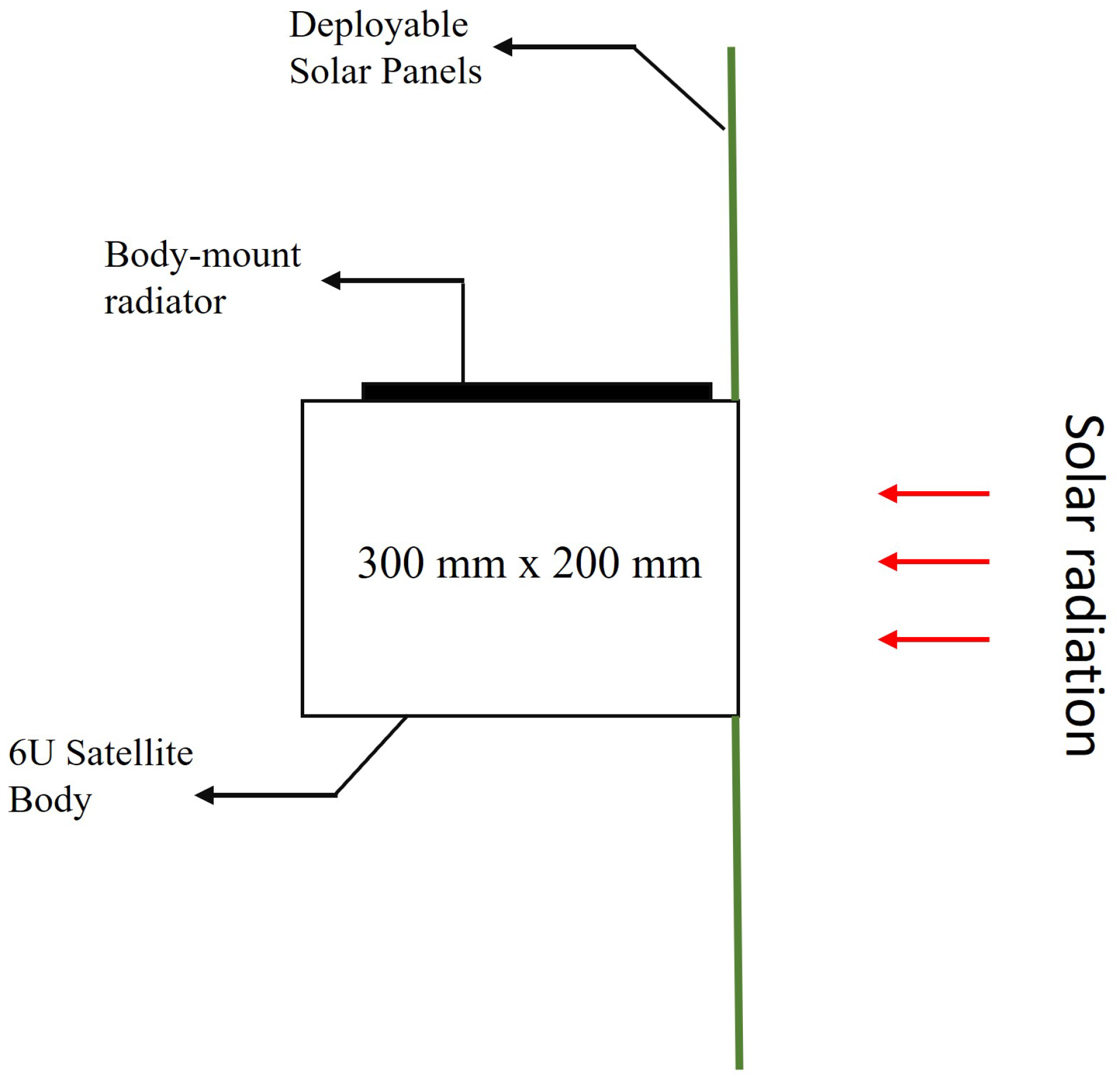
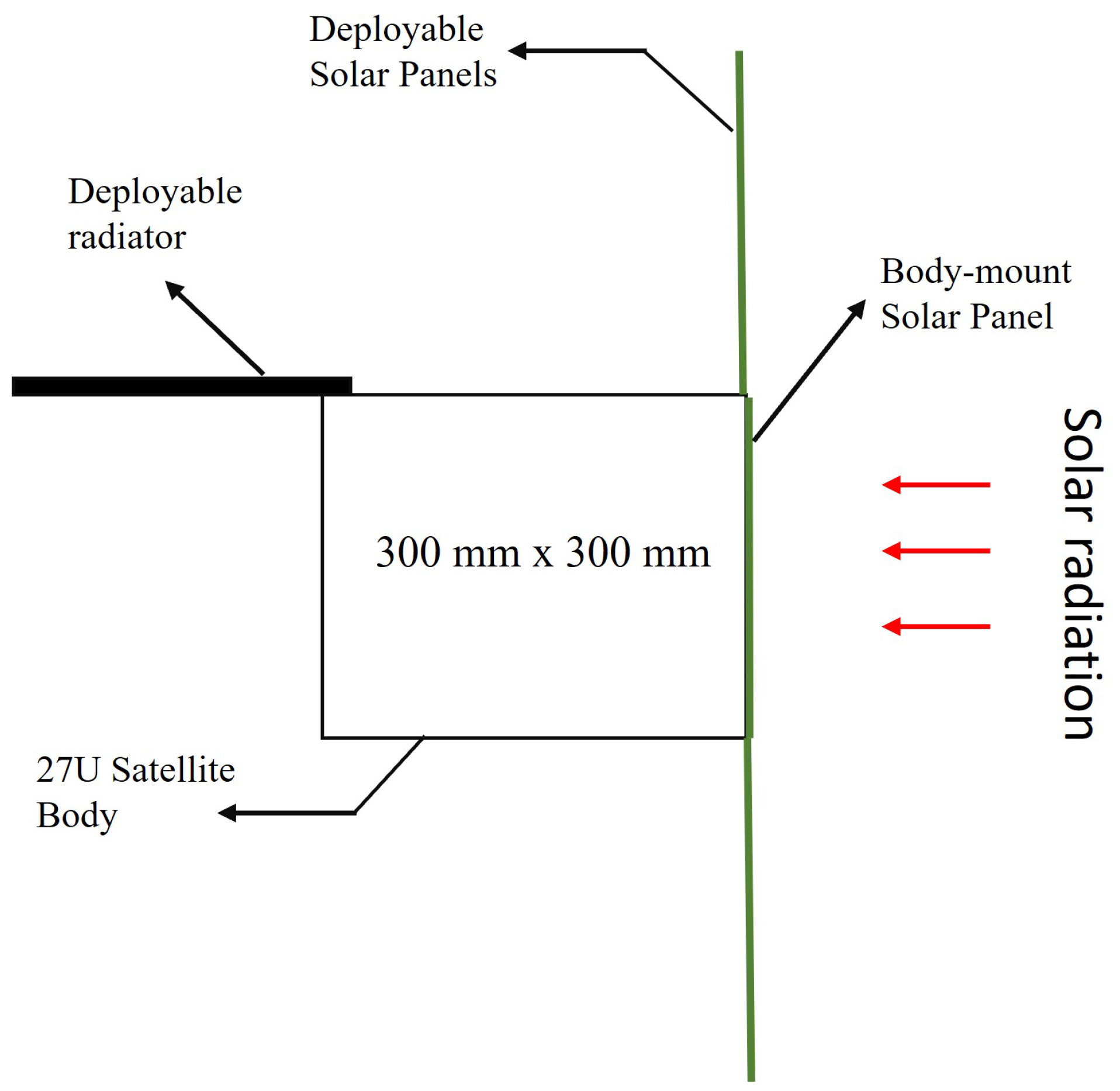
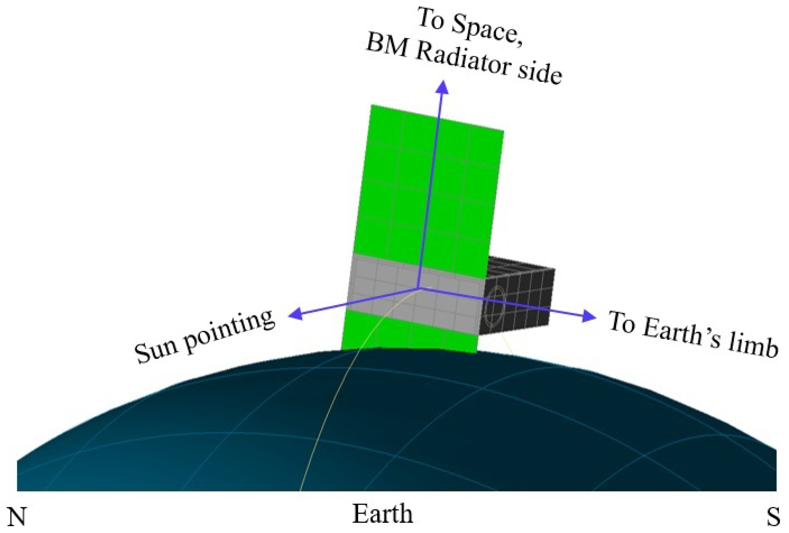
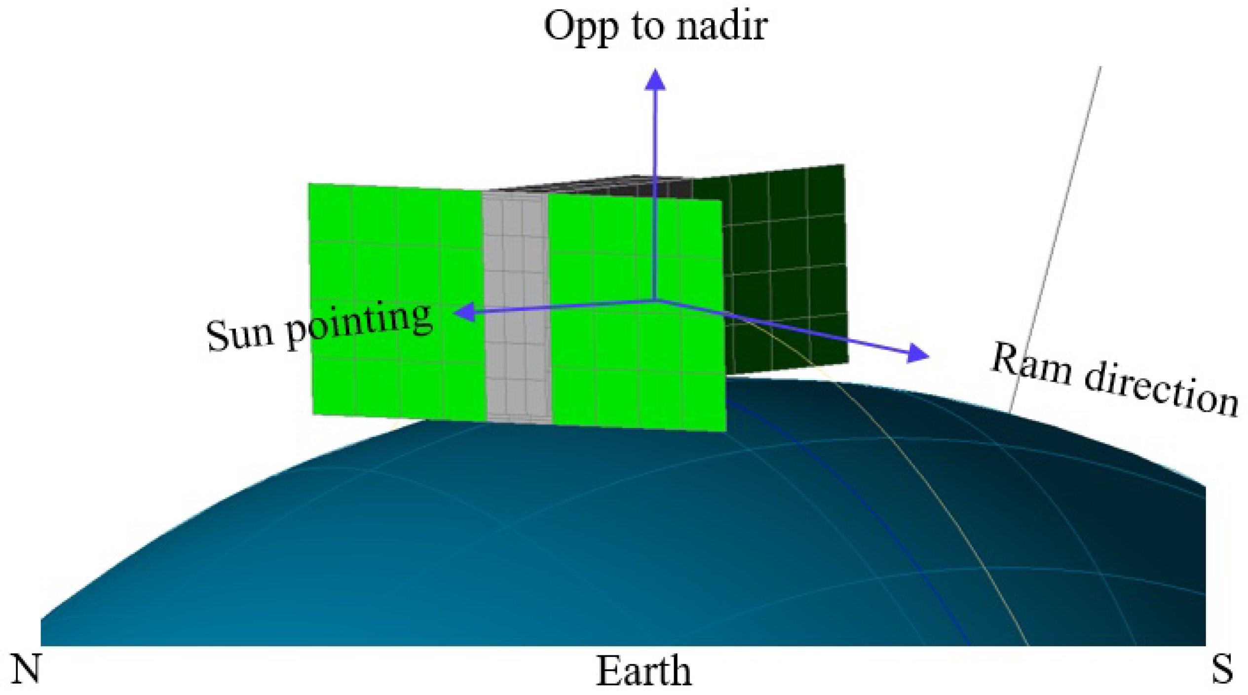
Firstly, a body-mount radiator is studied. Based on the advanced standard for CubeSats [4], the maximum surface area of the body-mount radiator on a 6U satellite is not more than 200 mm × 300 mm. However, full surface area cannot be utilized due to a few mechanical constraints, and hence the maximum area is assumed to be 290 mm × 180 mm (0.0522 m 2 ). Similarly, the size of the radiator panel for a 27U satellite is considered to be 300 mm × 300 mm (0.09 m 2 ). The Figure 5 and Figure 6 illustrate the orientation of the body-mount and deployable radiators for 6U and 27U satellites with respect to the sun.
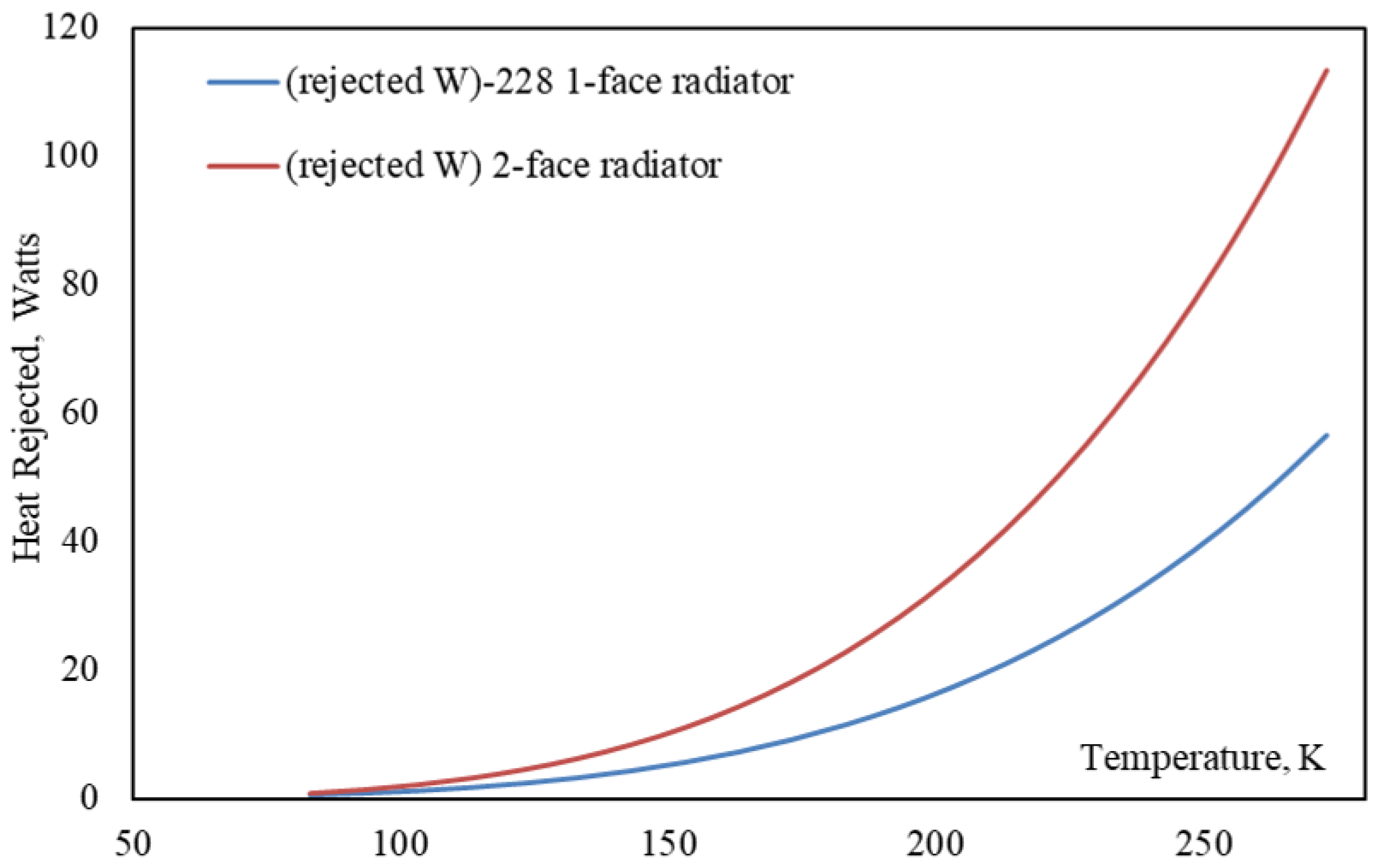
As can be seen in Figure 7, total heat rejected by both the body-mount (BMR) and deployable radiators (DR) are increasing exponentially (due to fourth power of T) when the temperature of the radiator is increased for a constant radiating surface area of 0.2 m 2 . Total heat rejected for the deployable radiator is higher because of double-active radiating surfaces, whereas the BMR has a single-active radiating surface. For the above calculations, it is assumed that the radiating surfaces are coated with black paint which has an emissivity of 0.85. The radiator is mounted below the solar panel for the 6U configuration, so they do not absorb much heat if exposed to the sun but, typically the radiators are painted white. 
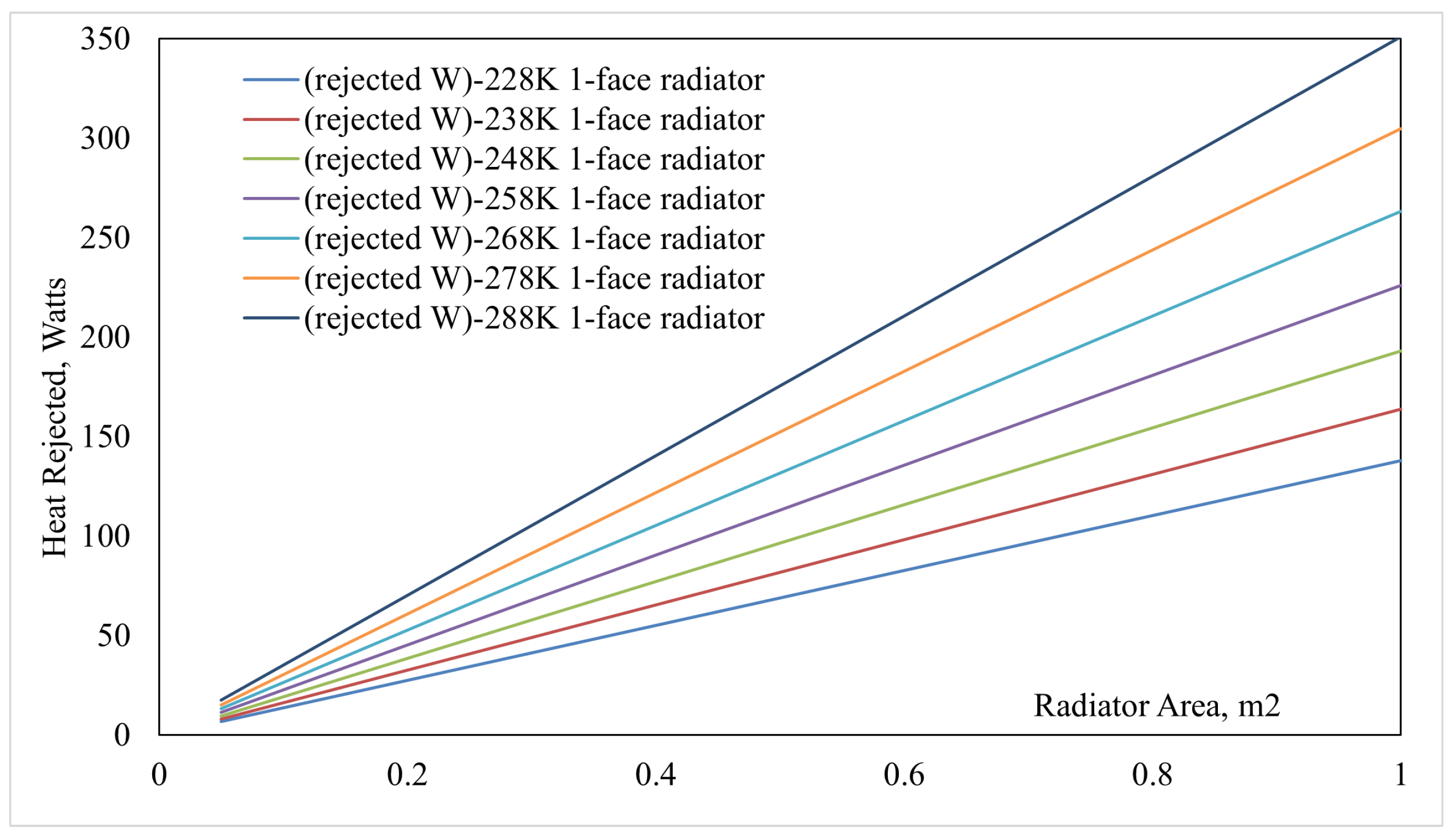
Figure 8 illustrates the relationship between radiator area ( A r a d ), temperature ( T r a d ), and total heat to be dissipated ( Q i n t e r n a l ). For a constant temperature, the total heat loss into deep space increases with increase in radiator surface area, and this variation is plotted for different radiating temperatures. Placement of the radiator panels on the satellite body is another important decision as the radiator should not be exposed to solar radiation, which is a major heat source. A typical configuration for BMR radiator on a 6U satellite body is shown in Figure 5. In the same way, deployable radiator configuration is also implemented on the satellite body. These panels are thermally isolated from rest of the satellite body to minimize thermal conduction but a strong thermal coupling is established for the detector/component of interest which needs to be cooled.
Thermal storage devices can be used to reduce the surface area of the radiator panels, which indirectly reduces the peak load if there is a transient heat load in the system. However, it is still challenging for small satellite thermal control technologies. Thermal dissipation for high power small satellites is challenging using only a body-mount radiator panel, and this is best addressed by increasing the radiating area by means of deployable panels. If deployable radiator panels are used, it is very important to ensure that the thermal conductivity is higher for the hinges used. Flexible thermal straps along with proper mechanical hinges, which have variable bending angles, can be used to deploy radiators [33]. Flexible thermal straps can be considered for thermal connection between the heat dissipating element and the deployable radiator.
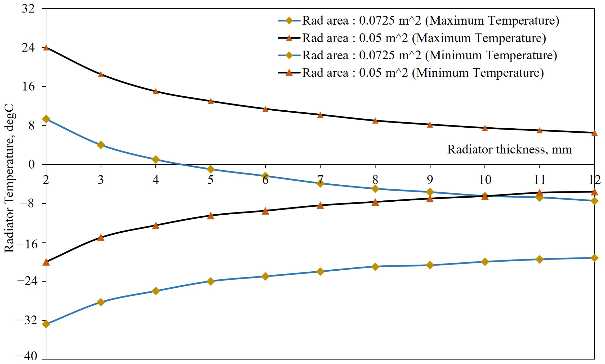
Besides radiator surface area, thickness also has a considerable effect on its temperature. According to [34], Mackay and Leventhal et al. derived relationships for heat transfer from an uniform plate heated at one edge. For a thin rectangular deployable radiator radiating in free space, it is assumed that the heat enters uniformly at the fin base and then it passes from the fin faces by radiation [33]. Heat dissipated by the fin faces is given by Equation (20) and this relationship takes thickness parameter (L) into consideration.
q a c t u a l = 2 k δ L σ ϵ 5 k δ 1 2 T b 5 T a 5 1 2
where, q a c t u a l —Actual heat input at the base of the fin, δ —width of the fin, k—Thermal conductivity, L—Radiator thickness, T b —Radiator base temperature, T a —Radiator tip temperature.
The fin efficiency is calculated from Equation (20). It is defined as the ratio of the actual heat dissipation to the ideal dissipation [35]. In ideal heat dissipation, the entire fin is at the base temperature considered.
q I d e a l = 2 σ ϵ δ L T b 4
η = q a c t u a l q i d e a l

3.6. Heat Pipes

Heat pipes are two-phase heat transfer devices that are categorized as one of the efficient passive thermal control methods for space applications because they do not need any additional power for their operation [36]. With smaller cross sections and high thermal conductance, these devices are capable of transferring heat over a long distance within the satellite. Heat pipes are broadly divided into three sections, namely: evaporator, adiabatic, and condenser. A typical heat pipe as illustrated in Figure 9 [37] has one evaporator section that takes heat from a heat source. The heat causes change of phase of the working fluid (water is used in this study) from liquid to vapor and moves to the adiabatic or transportation section due to increased vapor pressure at the evaporator section and then the vapor reaches the condenser section where condensation rejects the latent heat of the fluid to the sink. The condensed liquid then moves back to the evaporator section due to capillary pumping action [11,31]. The size of the heat pipe entirely depends on the heat load that it is subjected to. Constant Conductance heat Pipes (CCHP) are the basic and standard isothermal heat pipes whose thermal conductivity also can be varied by changing the physical properties such as pore diameter, porosity, and permeability [38].
Depending on the working fluid, wick structure, size, and operational temperature, heat pipes undergo various heat transfer limitations [39]. Total and effective heat pipe lengths are given in Equations (21) and (22).
l t o t a l = l e + l a d + l c
l e f f = 1 2 ( l e + l c ) + l a d
Heat pipe parameters used in this study are given in Table 3 and these values are derived based on available volume within the satellite.
In this study, the heat pipes are considered to be directly embedded onto both heat exchanger (HX) and radiator aluminum panels to maximize the heat transfer rate. Embedded heat pipes typically increase the effective thermal conductivity by several factors [40].

4. Mechanical Design and Thermal Modelling of 6U CubeSat

4.1. Mechanical Design Considerations

Figure 10 shows a generic 6U satellite configuration with most heat-dissipating internal components such as batteries, avionics, actuators, communication module, payload and a cryocooler. A deployable radiator designed for both of these configurations are analyzed numerically. Radiator panels are mounted to one of the larger satellite surfaces in these configurations.
The most heat dissipating elements are directly attached to a baseplate manufactured from aluminum 6061-T6. For the deployable radiator, the hinge mechanism keeps the radiator at stowed position below the deployable solar panel. Radiator is deployed into deep space after the solar panels are released from Hold Down and Release mechanism (HDRM). The base of the radiator is connected to the heat exchanger using high thermal conductive links such as thermal straps and thermal interface materials in order to improve the rate of heat transfer. The baseplate in this design accommodates a micro cryocooler and payload electronics. The avionics subsystem in the satellite is separately linked to the satellite external structure to keep them under operating temperature limits.
The proposed mass distribution for two satellite design configurations are listed in Table 4.
Thermo-optical properties of some of the components that are considered in the proposed 6U satellite design are listed in Table 5.

4.2. Environmental Load Studies and Orbit Parameters

Optimization is carried out on the satellite such that the design is able to handle the environmental heat loads for any orbital inclination and earth seasons. Orbital inclination varying from 0 < i < 97.3 degrees is studied to confirm the design is optimum for all the external heat load conditions. The variation of beta angles for every inclination is extracted from Systems Tool Kit (STK) software and verified with a commercial thermal analysis software, Thermal Desktop®.
Thermal simulations are carried out for four Earth seasons and seasonal environmental heat loads and the Earth’s seasonal variations are shown in Figure 11. All the Earth-bound Low Earth Orbits (LEO) will experience the same environmental thermal loads during its mission period, and they affect the thermal behaviour of the satellite components. Hence, the thermal design should consider all these fluctuations of the thermal loads. For the given orbital parameters, worst case mission conditions will be identified for the given satellite configurations and analyzed numerically. In general, for satellite thermal design, two extreme cases are the worst conditions.
  • Worst cold condition: Satellite at LEO will experience coldest temperature in orbit once a year, and it will happen during the Northern hemisphere summer where the satellite will receive lesser flux from the sun. Earth is located at aphelion, and most of the electronics and payloads are turned off. Beginning of the life (BOL) thermo-optical parameters are used.
  • Worst hot condition: Satellite at LEO receives 10% higher than the satellite would receive during summer. This happens during winter conditions. Earth is located at perihelion, and all the electronics and payloads are operating at their peak power. End of the life (EOL) thermo-optical parameters are used.
The orbital properties are illustrated pictorially in Figure 11. In addition to these properties, other important properties that should be considered for thermal calculations are beta angle, orbital inclination, and orbit type. Beta angle ( β ) is defined as the angle between the solar vector and satellite orbital plane. This angle varies as the orbit precesses around the Earth and as the Earth moves around the sun. This angle correlates to how much sun light falls onto the satellite surfaces. For a higher beta angle, the satellite spends more of the orbit in the sun. This angle varies with the inclination of the orbit. If the orbit is not sun synchronous, β will move through the range as given in Equation (23) [41], but it has some limitations for higher inclination orbits.
β = ± ( 23.5 + | i | )
where, i—orbital inclination, varies from 90 ° β + 90 ° . Beta angles where the sun is north of the orbit plane are considered positive. However, due to orbit precession, the right ascension of ascending node varies with time and hence the β equation is modified as in Equation (24) [11].
β = sin 1 cos Γ sin Ω sin i sin Γ cos ϵ cos Ω sin i + sin Γ sin Γ cos i
where, Γ —Ecliptic true solar longitude, Ω —Right ascension of ascending node (RAAN), ϵ is Obliquity of the ecliptic (currently the tilt is at 23.5), and i is the orbit’s inclination. RAAN and i are dependent on the satellite’s orbit but Γ is a function of earth’s position in orbit around the sun [42]. Two factors that affect the beta angle are the change of seasons and perturbation of the orbit due to earth oblateness. As the beta angle varies, there are two consequences of interest to be considered [41].
  • Planet shadow varies: Fraction of sunlight reaching the satellite reduces. This is illustrated in Figure 12.
  • The incident solar intensity varies. Variation of solar intensity ranges from 0 to 90 degrees and it is clearly seen from the variations plotted using System Tools Kit (STK) tool. The relationship between the sun season and beta angles is also shown in Figure 13.
Satellite in low earth circular orbits spends approximately 37% in eclipse and 63% in sunlight for low inclination orbits. Satellite at 408 km altitude, eclipse duration gradually reduces until when the beta angle approximately equals to 70 degrees as shown in Figure 12 [41].

4.3. Geometrical and Thermal Mathematical Model

The Geometrical Mathematical Model (GMM) is a mathematical representation of physical surfaces of the components. It is used to calculate radiation coupling between surfaces as well as heating rates due to environmental heat fluxes. The radiation interchange couplings and environmental heat fluxes calculated by the GMM are used as inputs to the Thermal Mathematical Model (TMM). The TMM consists of a resistor-capacitor network of the spacecraft to calculate heat flows and temperatures.
A thermal model of the 6U satellite was developed using the Thermal Desktop (TD) tool, which performs both the GMM and TMM components of the calculation. All the satellite components such as outer metal plates of the satellite, internal components, payload, and avionics are modelled as solid blocks and solar panels are modelled as 2D surfaces to reduce computational time. Moreover, the variation in temperature across the thickness is insignificant. However, the mass of each elements in both satellite configurations are kept the same as provided in Table 4. In the process of developing thermal mathematical model, thermal couplings were introduced to simulate the physical contact between various satellite components.
Convergence studies with different finite elements were carried out on the thermal model and confirmed that the change in temperature ( Δ T ) is negligible(<1%). Thermal models for these satellites are built such that it reflects all the physical connections, thermal behaviour, and to have the same actual mass. The 6U satellite thermal model has a mass of 9 kg.
Thermal contact conductance (TCC) properties are generally empirically derived. However, a table of standard values for bolted interfaces from the Spacecraft Thermal Control Handbook are used in this study. All the major contacts with TCC are listed in Table 6 [11].

4.4. Thermal Analysis—Heat Load Parameters

Thermal analyses were performed for the given mission parameters and heat loads for both extreme temperature conditions. The 6U satellite with all the major heat dissipating elements such as a mini cryocooler, battery pack, avionics and payload are considered in the thermal model. Passive thermal control methods include heat pipes, thermal straps, and body-mount radiator are analyzed initially. Later, radiator design for the same 6U satellite configuration is analyzed for various design parameters.

5. Thermal Analysis and Results Discussion

5.1. Thermal Analysis of a 6U Satellite with Heat Pipes

For the satellite configuration shown in Figure 14 and Figure 15 and heat load conditions as listed in Table 7, thermal analyses were carried out for both worst hot and worst cold conditions with constant conductance heat pipes (CCHP). The thermal model of the 6U satellite with cryogenic payload is shown in Figure 16. This thermal model has a micro cryocooler modelled as a cylinder with a copper cold finger, generic cryogenic payload also modelled as a cylinder, and heat dissipating elements such as electronics, heaters, and batteries. The thermal contact conductance values used are provided in Table 6. For this study, it is considered that the satellite is orbiting around the earth at 535 km equatorial orbit with 5° inclination. As can be seen from the thermal model, one of the larger surfaces of the 6U satellite (maximum radiator area considered for BMR is 290 mm × 250 mm) is used as the radiator plate to which the heat pipes are attached. This study considers a generic mid-wave infrared instrument whose detector must be kept around 95K as reference. To provide this cryogenic cooling, a miniature stirling cryocooler (Ricor K508) is considered as it provides better performance at low input power.
Ricor K508N comes with a built-in compressor unit, and it consumes a maximum of 20W during its operation. The cryocooler and heaters are mounted to the Heat Exchanger (HX) plate that is firmly attached to the satellite structure. The cryocooler cold head is assumed to be connected to the IR instrument’s detector using high conductance copper thermal straps covered with MLI to minimize the radiation loss and to aid the strap conductance. Two different radiator configurations are analyzed to dissipate the waste heat from the HX and the instrument.
  • Body-mount radiator: One of the large surfaces of the 6U satellite is modelled as a body-mount radiator with high emissivity paint. CCHP are modelled such that it connects both HX and the radiator panel. From the calculation, it was found that the heat pipe with 300 mm long can carry up to 5 W of power. Hence, four heat pipes are used and each has a condenser length of 60mm and an evaporator length of 120 mm. The mass of the satellite’s structural panel with embedded heat pipes is 860 g. The temperature summary of the body-mount radiator with embedded heat pipes is shown in Figure 16. All the internal components are exchanging heat between themselves and the external plates of the satellite exchange the heat with external space environment. The amount of heat absorbed or emitted from any component is strongly dependent on its surface thermo-optical properties.
    The 6U satellite with BMR is analyzed for worst hot case orbital condition. The MWIR instrument in this study is assumed to take science measurement all the time in the orbit and hence the micro cryocooler considered to be running continuously to meet the instrument’s thermal requirement at the detector. Cryocooler is mounted to the HX and heat pipes are connected to both HX and BMR. The main objective of this arrangement is to keep the temperature within the system interface temperature of 25 °C to 30 °C. However, the simulation results show that the body-mounted radiator panel with four heat pipes is not able to provide sufficient thermal performance as the temperature of the Cryocooler unit (CCU) exceeds its maximum operating temperature of 85 °C as seen in Figure 17. Since both CCU and HX are placed inside the satellite, their temperature should be maintained within the desirable limit in order to ensure the rest of the satellite components are safe for continuous satellite operation. An alternative thermal solution, deployable radiator, is studied for the same satellite configuration.
  • Deployable radiator: For the same 6U satellite thermal model, the radiator is changed to deployable configuration to compare the radiating capacity with BMR panel. As with the BMR, the deployable radiator is made from aluminum 6061-T6 with a thickness of 6 mm. CCHP are embedded to both HX and radiator separately and are linked together using thermal straps along the edges of the radiator panel to make it flexible. The surface area of the deployable radiator shown in Figure 18 is assumed to be 150 mm × 270 mm with 620 g of mass including heat pipes.
    The maximum operational range of CCU is −40 °C to +85 °C and the CCU temperature profile shown in Figure 19 indicates 35 °C of difference from its maximum limit. Although the temperature of CCU is within its operational limit, the overall system interface temperature, HX temperature in this case, remains high at 43 °C which is still higher for other components. When compared to BMR panel configuration, deployable radiator panel radiates two times higher for the same heat load.

5.2. Thermal Analysis of 6U satellite with Thermal Straps

In this case, a flexible copper thermal strap of the dimensions as indicated in Figure 3 is considered to be thermally coupled to the HX and the deployable radiator panel. With higher applied joint pressure, thermal coupling between the radiator and HX plate results from a large surface area attachment and both HX and the radiator panel are aluminum which has a relatively higher thermal conductivity. Since the thermal strap is coupled to the HX plate, it is assumed that the thermal strap is isothermal with HX temperature. The radiator panel is thermally isolated from the structure so that no parasitic heat loads flow into the radiator panel except through the deployable mechanism and only the thermal strap is the effective thermal path between the HX and the radiator panel for heat conduction. Considering the length of the thermal strap in this configuration, a large temperature gradient is expected between the end points of the strap. It is also assumed that deep space is 0 K and the radiator has a full view factor to space, a thermal simulation with the thermal strap and the radiator was carried out. Figure 20 and Figure 21 show the temperature profiles of the CCU, HX and the radiator panel. HX needs to be maintained between 10 °C to 20 °C and the simulation shows that the HX exceeds its operational limit with thermal straps. As the temperature of the radiator panel varies across its surface area, a few locations including radiator edges and middle regions were picked to plot the distributions and it is depicted in Figure 21.
Passive TCS studies carried out for a typical high powered 6U satellite platform using thermal straps and heat pipes clearly show that the proposed satellite configuration need to be equipped with an active TCS in order to keep the interface temperature within the desirable range, and the passive solutions described here are not efficient for such satellites with a cryogenic instrumentation.

5.3. Radiator Performance Evaluation Studies

As illustrated in Figure 22, Figure 23, Figure 24 and Figure 25, the temperature of the body-mount and deployable radiators remains almost constant for different inclinations varying from 0 to 90 degrees for both worst orbital conditions. However, the temperature increases significantly with a reduction in radiator surface area. As described using Equation (23), β varies with varying orbital inclination (i). For every i, β changes due to Earth’s seasonal variation. In this study, it is considered that the satellite is orbiting clockwise when observed from the sun or the sun is at north of the orbit plane and hence β assumed to vary from 0 to 90 ° [42]. As seen from Figure 13, there is a maximum β for every i and this maximum β us considered and plotted against varying inclination angles as shown in figures As illustrated in Figure 22, Figure 23, Figure 24 and Figure 25. These figures illustrate the relationship between the temperature of radiator panels, i, β , and radiator surface area. For a constant radiator area, the temperature of the radiator panel will fluctuate while varying i and β . However, due to radiator’s position in the satellite (placed just under the solar panels in this case), the temperature remains almost constant for all inclinations.
As with the body-mount radiator, the temperature of the deployable radiator for the orientation shown in Figure 6 also remains approximately constant for different inclination angles. Hence, the radiator designed for one orbit can also be used for other orbit conditions without altering too much and this is applicable only for the radiators that are not pointed to the sun at any instant in the orbit. If the mission requires specific pointing, additional environmental heat loads should be considered for the radiator design. It is observed from the plots that the effect of beta angle variation is not affecting the radiator temperature as the radiator is kept below the solar panels and the solar panels are assumed to have pointed to the sun.

5.4. Radiator Thickness and Thermal Coating Studies

The following set of simulations were carried out for sun-synchronous orbits. The sun synchronous orbit’s ascending node moves in the same direction and at the same average rate as the sun’s motion about the ecliptic plane by selecting the right combination of altitude and inclination [41]. Beta angle does not vary much for a satellite in a sun synchronous orbit and it helps to ignore environmental heat variation, but the seasonal variations still need to be considered. A special orbit, dawn-dusk, is studied and analyzed for the same thermal design, satellite attitude, orientation, parameters that were used for the equatorial orbit study.
From Figure 26 and Figure 27, it can be proven that the radiator with higher thermal mass (higher thickness) exhibits better performance than lower thermal mass (lower thickness). Increasing the radiating panel thickness lowers the radiator maximum temperature in orbit while keeping the radiating surface area constant. However, the temperature range of the radiator panel is minimized with an increase in mass. The radiating capacity can be altered using specialized surface paints as discussed in Section 3.2. A few commercially available surface coatings are studied for the radiator performance, and the results are shown in Figure 28 and Figure 29. The maximum radiator temperature can be lowered using low absorptivity paints and high emissivity paints which lowers the radiating temperature at hot and cold conditions. Both surfaces of the radiator are considered to have surface paints in the deployable radiator configuration as the panel radiates from both of its large surfaces, whereas in the body-mount configuration, only the radiating surface is applied with this coating and the other side is covered with a MLI. MLI in BMR helps to maintain the radiator at a steady state by avoiding radiation in and out from the radiator panel. Hence, body-mount radiator is considered to be a single-active face radiator, and deployable radiators are double-active face radiators. From the analysis, it can be said that the body-mount radiator panel can dissipate only 40–50% of the total heat that a full deployable radiator can dissipate. For the radiator mass of 0.4 kg, BMR’s temperature range is 23.1 °C to −10.1 °C and DR’s temperature range is 9.3 °C to −32.8 °C.
A constantly illuminated orbit with no eclipse phase is also simulated for the same thermal parameters and satellite configurations. This orbit provides constant power for the satellite components, but it increases the thermal load on different components exposed to the sun and this makes the thermal design more complex.

5.5. Discussion and Summary

Passive thermal control methods for cryogenic instrumentation, high power payloads and electronics on nano and micro satellite platforms may be a suitable solution, but in this design scenario, it fails to maintain the system interface temperature between 20 to 30 °C. However, there is a power threshold where a CubeSat will have adequate radiating capability. Hence, active thermal control techniques are recommended to be considered for such high power satellite missions. Active thermal control methods such as Loop Heat Pipes (LHP), mechanically pumped fluid loop systems, are being studied and considered suitable for solving thermal challenges in small satellite platforms. Radiator designs for different satellite configurations were analyzed and compared. A satellite radiator designed for a particular altitude, inclination, and specific orientation with respect to the sun can provide the same performance for other inclination angles only if the radiator panels are kept under the sun pointed solar panels. For this particular 6U design, as long as the BMR is not seeing the partial/full sun or exposed to direct solar flux, it is expected that the change in temperature of the radiator is minimal and within ±10 °C approximately. Radiator mass affects its performance to a larger extent. While keeping the available surface area constant, increasing the thickness increases the mass of the radiator panel fabricated from Al6061-T6. The higher the thickness or higher the mass of the panel, the lower the temperature difference and at the same time the overall radiator performance is increased.
Surface coatings were analyzed for a 6U satellite with body-mount and deployable radiator configurations. It is observed that the surface coatings greatly enhance the radiating capacity of the radiators for any satellite categories. Proper mounting methods and placement of the radiators are to be chosen very carefully in order to achieve the maximum heat loss into deep space. Most of the satellite radiators are designed to be pointed to deep space rather than at the Earth or the sun. Two 6U satellite configurations discussed in this study assumed that the radiators are pointed to deep space to minimize the environmental heat load. Some satellite missions or payload require specific pointing which could point the radiator to the sun for a few minutes. These special cases are carefully analyzed by calculating the total incoming environmental heat load to the radiator precisely. Radiator surfaces that faces the ram direction of the satellite need to be fabricated with high strength materials or should be thicker in order to deal with micrometeoroid impacts in low earth orbits and atomic oxygen effects which significantly erode the surface coatings before the end of the mission life.

6. Conclusions

Radiators are used on satellites to dump waste heat into deep space. Technological advancements and demand for high power payloads on small nanosatellite platforms increase the need for better thermal management systems. This study analyzed a few passive thermal control methods, such as multi-layer insulation, thermal straps, heat pipes, and passive radiators. Thermal straps are often used as high conductive flexible thermal links to transfer heat from inaccessible locations in the satellite to various other parts. An experimental investigation is carried out on a custom-designed thermal strap to characterize its conductance for different heat loads. The passive radiator is designed and studied in detail for many parameters, such as radiating surface area, radiator mounting type, surface coating, and radiator mass for a 6U satellite platform. The effect of different orbital inclinations on the passive radiator is studied for the same satellite geometric parameters.

Author Contributions

Design, S.S.; methodology, S.S., A.C.; Analysis, S.S.; Testing and validation, S.S.; investigation, S.S., A.C., D.V., B.L.; resources, S.S.; writing—original draft preparation, S.S.; writing—review and editing, S.S., D.V., B.L.; supervision, A.C., D.V., B.L.; project administration, S.S., A.C. All authors have read and agreed to the published version of the manuscript.

Funding

This work was completed from Amal Chandran’s NTU startup grant “CubeSat for Earth Science observations”.

Institutional Review Board Statement

Not applicable.

Informed Consent Statement

Not applicable.

Data Availability Statement

Data available on request due to restrictions on privacy.

Acknowledgments

The corresponding author would like to thank the Satellite Research Centre (SaRC) at Nanyang technological University (NTU) for providing sufficient support in the form of software, facility, and past satellite mission data to carry out this study. Also, the author would like to thank CR technologies for supporting with an academic Thermal Desktop® licence.

Conflicts of Interest

The authors declare no conflict of interest.

Abbreviations

The following abbreviations are used in this manuscript:
ATCSActive Thermal Control System
PTCSPassive Thermal Control System
MLIMulti-layer Insulation
MWIRMid-Wave InfraRed
SWIRShort-Wave InfraRed
TIRThermal InfraRed
DCDark Current
IRInfraRed
EOEarth Observation
ATOXAtomic Oxygen
UVUltraviolet Radiation
EOLEnd-of-Life
BOLBeginning-of-Life
TCCThermal Contact Conductance
TVACThermal Vacuum Chamber
LEOLow Earth Orbit
GMMGeometrical Mathematical Model
TMMThermal Mathematical Model
TDThermal Desktop
HXHeat Exchanger
CCUCryo Cooler Unit
BMRBody-Mount Radiator
DRDeployable Radiator
TCSThermal Control System

References

  1. Golkar, A.; Salado, A. Definition of New Space—Expert Survey Results and Key Technology Trends. IEEE J. Miniaturizat. Air Space Syst. 2021, 2, 2–9. [Google Scholar] [CrossRef]
  2. Denis, G.; Alary, D.; Pasco, X.; Pisot, N.; Texier, D.; Toulza, S. From new space to big space: How commercial space dream is becoming a reality. Acta Astronaut. 2020, 166, 431–443. [Google Scholar] [CrossRef]
  3. You, Z. (Ed.) Chapter 4—Micro/Nano Satellite Integrated Electronic System. In Space Microsystems and Micro/nano Satellites; Micro and Nano Technologies; Butterworth-Heinemann: Amsterdam, The Netherlands, 2018; pp. 115–146. [Google Scholar] [CrossRef]
  4. Hevner, R.; Holemans, W.; Puig-Suari, J.; Twiggs, R. An Advanced Standard for CubeSat. In Proceedings of the 25th Annual AIAA/USU Conference on Small Satellites, Logan, UT, USA, 8 August 2011. [Google Scholar]
  5. Rabionet, M.C. Study of Future Perspectives of Micro/Nanosatellites Constellations in the Earth Observation Market. 2019. Available online: https://upcommons.upc.edu/bitstream/handle/2117/174918/REPORT_fitxer%20de%20consulta.pdf?sequence=6 (accessed on 1 February 2022).
  6. De Aragon, A.M. Future Applications of Micro/Nano-Technologies in Space Systems. 1996. Available online: https://www.esa.int/esapub/bulletin/bullet85/mart85.htm (accessed on 2 February 2022).
  7. Inalhan, G.; Yillikci, K.; Ure, K.; Koyuncu, E. The Future of Micro/Nano-Satellite Based Earth Observation and Communication Systems. 2001. Available online: https://www.mcgill.ca/iasl/files/iasl/2015-lachs-panel3a-6-inalhan_et_al.pdf (accessed on 1 February 2022).
  8. Han, Y.; Zhang, A. Cryogenic technology for infrared detection in space. Sci. Rep. 2022, 12, 2349. [Google Scholar] [CrossRef] [PubMed]
  9. Grant, B.G.; Palmer, J.M. The Art of Radiometry; SPIE: Bellingham, WA, USA, 2009. [Google Scholar]
  10. Thermal Control. 2021. Available online: https://www.nasa.gov/smallsat-institute/sst-soa/thermal-control (accessed on 6 March 2022).
  11. David, G.G. (Ed.) Spacecraft Thermal Control Handbook, Volume I: Fundamental Technologies; AIAA Education Series; The Aerospace Press: El Segundo, CA, USA, 2002; pp. 19–36. [Google Scholar]
  12. Anderson, L.; Davidson, R.L.; Swenson, C. SSC 18-WKVII-08 The Active CryoCubeSat Project: Testing and Preliminary Results. 2018. Available online: https://digitalcommons.usu.edu/cgi/viewcontent.cgi?article=4273&context=smallsat (accessed on 21 February 2022).
  13. Xue, Y.; Li, Y.; Guang, J.; Zhang, X.; Guo, J. Small satellite remote sensing and applications—History, current and future. Int. J. Remote Sens. 2008, 29, 4339–4372. [Google Scholar] [CrossRef]
  14. Boushon, K.E. Thermal Analysis and Control of Small Satellites in Low Earth Orbit. 2018. Available online: https://scholarsmine.mst.edu/cgi/viewcontent.cgi?article=8755&context=masters_theses (accessed on 16 January 2022).
  15. Fick, W.; Gassmann, K.U.; Haas, L.D.; Haiml, M.; Hanna, S.; Hübner, D.; Höhnemann, H.; Nothaft, H.P.; Thöt, R. Infrared detectors for space applications. Adv. Opt. Technol. 2013, 2, 407–421. [Google Scholar] [CrossRef]
  16. Ross, R.G.J. Cryocoolers for Space Applications. 2015. Available online: https://www2.jpl.nasa.gov/adv_tech/coolers/Cool_ppr/CEC2015-Short%20Course%20Session%204.pdf (accessed on 8 February 2022).
  17. Rando, N.; Lumb, D.; Bavdaz, M.; Martin, D.; Peacock, T. Space science applications of cryogenic detectors. Nucl. Instrum. Methods Phys. Res. Sect. A Accel. Spectromet. Detect. Assoc. Equip. 2004, 522, 62–68. [Google Scholar] [CrossRef]
  18. Miyakita, T.; Hatakenaka, R.; Sugita, H.; Saitoh, M.; Hirai, T. Development of a new multi-layer insulation blanket with non-interlayer-contact spacer for space cryogenic mission. Cryogenics 2014, 64, 112–120. [Google Scholar] [CrossRef]
  19. Miyakita, T.; Hatakenaka, R.; Sugita, H.; Saitoh, M.; Hirai, T. Evaluation of Thermal Insulation Performance of a New Multi-Layer Insulation with Non-Interlayer-Contact Spacer. In Proceedings of the 45th International Conference on Environmental Systems, Bellevue, WA, USA, 12–16 July 2015. [Google Scholar]
  20. Corpino, S.; Caldera, M.; Nichele, F.; Masoero, M.; Viola, N. Thermal design and analysis of a nanosatellite in low earth orbit. Acta Astronaut. 2015, 115, 247–261. [Google Scholar] [CrossRef] [Green Version]
  21. Ross, R. Quantifying MLI Thermal Conduction in Cryogenic Applications from Experimental Data. IOP Conf. Ser. Mater. Sci. Eng. 2015, 101, 012017. [Google Scholar] [CrossRef] [Green Version]
  22. Kan, H.K.A. Space Environment Effects On Spacecraft Surface Materials. In Radiation Effects on Optical Materials; Levy, P.W., Ed.; International Society for Optics and Photonics, SPIE: Bellingham, WA, USA, 1985; Volume 0541, pp. 164–179. [Google Scholar] [CrossRef]
  23. Anvari, A.; Farhani, F.; Niaki, K. Comparative Study on Space Qualified Paints Used for Thermal Control of a Small Satellite. Iran. J. Chem. Eng. 2009, 6, 50–62. [Google Scholar]
  24. Roussel, J.F.; Alet, I.; Faye, D.; Pereira, A. Effect of Space Environment on Spacecraft Surfaces Control in Sun-Synchronous Orbits. J. Spacecr. Rocket. 2004, 41, 812–820. [Google Scholar] [CrossRef]
  25. Liu, T.; Sun, Q.; Meng, J.; Pan, Z.; Tang, Y. Degradation modeling of satellite thermal control coatings in a low earth orbit environment. Sol. Energy 2016, 139, 467–474. [Google Scholar] [CrossRef]
  26. Dhuley, R.; Ruschman, M.; Link, J.; Eyre, J. Thermal conductance characterization of a pressed copper rope strap between 0.13K and 10K. Cryogenics 2017, 86, 17–21. [Google Scholar] [CrossRef]
  27. Henninger, J.H. Solar Absorptance and Thermal Emittance of Some Common Spacecraft Thermal Control Coatings. NASA. 2013. Available online: https://ntrs.nasa.gov/citations/19840015630 (accessed on 6 March 2022).
  28. Lécossais, A.; Jacquemart, F.; Lefort, G.; Dehombreux, E.; Beck, F.; Frard, V. Deployable Panel Radiator. Available online: http://hdl.handle.net/2346/72955 (accessed on 16 July 2017).
  29. Shanmugasundaram, S.; Chandran, A.; Joshi, S.C.; Edwin, T.H.T.; Valentini, D.; Olschewski, F. A Comparison Study on Thermal Control Techniques for a Nanosatellite Carrying Infrared Science Instrument. Available online: https://hdl.handle.net/2346/86412 (accessed on 31 July 2020).
  30. Hengeveld, D.; Wilson, M.; Moulton, J.; Taft, B.; Kwas, A. Thermal Design Considerations for Future High-Power Small Satellites. In Proceedings of the 48th International Conference on Environmental Systems, Albuquerque, NM, USA, 8–12 July 2018. [Google Scholar]
  31. Karam, R.D. Satellite Thermal Control for Systems Engineers; American Institute of Aeronautics and Astronautics: Reston, VA, USA, 1998. [Google Scholar]
  32. Sam, K.F.C.H.; Deng, Z. Optimization of a space based radiator. Appl. Therm. Eng. 2011, 31, 2312–2320. [Google Scholar]
  33. Janzer, K.; Langer, M.; Killian, M.; Krejci, D.; Reissner, A. Thermal Control of High Power Applications on CubeSats. In Proceedings of the 69th International Astronautical Congress, Bremen, Germany, 1–5 October 2018. [Google Scholar] [CrossRef]
  34. Sparrow, E. Radiation Heat Transfer between Surfaces. In Advances in Heat Transfer; Elsevier: Amsterdam, The Netherlands, 1965; Volume 2, pp. 399–452. [Google Scholar] [CrossRef]
  35. Iwata, N.; Iwata, N.; Nakanoyaa, S.; Nakamura, N.; Takeda, N.; Tsutsui, F. Thermal Performance Evaluation of Space Radiator for Single-Phase Mechanically Pumped Fluid Loop. J. Spacecr. Rocket. 2021, 59, 225–235. [Google Scholar] [CrossRef]
  36. Jentung, K. Introduction to Heat Pipes. Available online: https://tfaws.nasa.gov/wp-content/uploads/TFAWS2015-SC-Heat-Pipes.pdf (accessed on 21 January 2022).
  37. Brouwer, H.; de Groot, Z.; Guo, J.; van Gerner, H.J. Solving the Thermal Challenge in Power-Dense CubeSats with Water Heat Pipes. In Proceedings of the 31st Annual AIAA/USU Conference on Small Satellites, Logan, UT, USA, 5–10 August 2017. [Google Scholar]
  38. Meseguer, J.; Pérez-Grande, I.; Sanz-Andrés, A. 11—Heat pipes. In Spacecraft Thermal Control; Meseguer, J., Pérez-Grande, I., Sanz-Andrés, A., Eds.; Woodhead Publishing: Amsterdam, The Netherlands, 2012; pp. 175–207. [Google Scholar] [CrossRef]
  39. Nemec, P.; Čaja, A.; Malcho, M. Mathematical model for heat transfer limitations of heat pipe. Math. Comput. Model. 2013, 57, 126–136. [Google Scholar] [CrossRef]
  40. Weyant, J.; Garner, S.; Johnson, M.; Occhionero, M. Heat pipe embedded AlSiC plates for high conductivity—Low CTE heat spreaders. In Proceedings of the 2010 12th IEEE Intersociety Conference on Thermal and Thermomechanical Phenomena in Electronic Systems, Las Vegas, NV, USA, 2–5 June 2010; pp. 1–6. [Google Scholar] [CrossRef] [Green Version]
  41. Rickman, S.L. Introduction to Orbital Mechanics and Spacecraft Attitudes for Thermal Engineers; NASA Tfaws; NASA: Washington, DC, USA, 2020; pp. 116–129.
  42. Sumanth, R.M. Computation of Eclipse Time for Low-Earth Orbiting Small Satellites. Int. J. Aviat. Aeronaut. Aerosp. 2019, 6, 15. [Google Scholar] [CrossRef]
Figure 1. Payload configuration.
Applsci 12 02858 g001
Figure 2. Thermal strap conductance.
Applsci 12 02858 g002
Figure 3. Thermal Strap—test sample.
Applsci 12 02858 g003
Figure 4. Thermal strap conductance.
Applsci 12 02858 g004
Figure 5. BMR-Satellite Orientation with respect to Sun.
Applsci 12 02858 g005
Figure 6. DR-Satellite Orientation with respect to Sun.
Applsci 12 02858 g006
Figure 7. Heat rejection with temperature.
Applsci 12 02858 g007
Figure 8. Heat rejection capacity with surface area.
Applsci 12 02858 g008
Figure 9. Heat Pipe—schematic.
Applsci 12 02858 g009
Figure 10. 6U—Mechanical design.
Applsci 12 02858 g010
Figure 11. Variation in environmental heat loads due to Earth’s season.
Applsci 12 02858 g011
Figure 12. Fraction of time spent in sunlit and eclipse.
Applsci 12 02858 g012
Figure 13. Beta angle variation—STK.
Applsci 12 02858 g013
Figure 14. Satellite’s attitude in orbit—BMR.
Applsci 12 02858 g014
Figure 15. Satellite’s attitude in orbit—DR.
Applsci 12 02858 g015
Figure 16. 6U Satellite Body-mount radiator.
Applsci 12 02858 g016
Figure 17. 6U Satellite body-mount radiator with heat pipes—Temperature.
Applsci 12 02858 g017
Figure 18. 6U Satellite deployable radiator with heat pipes—Thermal model.
Applsci 12 02858 g018
Figure 19. 6U Satellite deployable radiator with heat pipes.
Applsci 12 02858 g019
Figure 20. 6U Satellite deployable radiator with Thermal Straps—CC and HX Temperature.
Applsci 12 02858 g020
Figure 21. 6U Satellite deployable radiator with Thermal Straps—Radiator Temperature.
Applsci 12 02858 g021
Figure 22. BMR temperature variation with inclination and beta angle—Worst hot condition.
Applsci 12 02858 g022
Figure 23. DR temperature variation with inclination and beta angle—Worst hot condition.
Applsci 12 02858 g023
Figure 24. BMR temperature variation with inclination and beta angle—Worst cold condition.
Applsci 12 02858 g024
Figure 25. DR temperature variation with inclination and beta angle—Worst cold condition.
Applsci 12 02858 g025
Figure 26. BMR —Thickness Study.
Applsci 12 02858 g026
Figure 27. DR—Temperature variation with radiator thickness.
Applsci 12 02858 g027
Figure 28. BMR Surface coating study.
Applsci 12 02858 g028
Figure 29. DR Surface coating study.
Applsci 12 02858 g029
Table 1. Infrared instrument—Detector temperature requirements [16,17].
IR Wavelength CategoryWavelength (μm)Detector Temperature (K)
Near-Infrared (NIR)0.75–1.4300
Short Wavelength Infrared (SWIR)0.75–1.4300
Mid Wavelength Infrared (MWIR)3–850–80
Long Wavelength Infrared (LWIR)8–1550–80
Far Infrared (FIR)15–10000.05–20
Table 2. Thermal strap materials.
Material NameThermal Conductivity, k, W/m·K
Graphene∼3500
Pyrolytic graphene∼1500
Graphite fiber∼800
Copper∼450
Aluminium∼225
Note: ∼:- Actual values may change but they remain close to the tabulated values.
Table 3. Heat pipe design parameters used.
ParametersSymbolValues
Vapor core diameter r v 0.003
Wall material-Copper
Working fluid-Water
Wall area (m 2 ) A w 0.0000026 × 10 6
Wall shape-circular
Evaporation length of heat pipe (m) l e 0.08
Adiabatic length of heat pipe (m) l a d 0.08
Condensation length of heat pipe (m) l c 0.12
Effective length of heat pipe (m) l e f f 0.18
Thermal conductivity of heat pipe material (W·m−1·K−1)λm389
Table 4. Mass distribution—6U satellite.
Components6U Mass (kg)27U Mass (kg)
Payload3.56.2
Avionics0.500.75
Battery0.50.9
Heat Exchanger0.400.75
Solar Panels0.3250.65
Satellite Structure3.26.9
Radiator0.350.9
Table 5. Surface properties—Used.
ComponentsMaterialsCoatingAbsorptivityEmissivity
Solar PanelsFR4FR4 default0.60.7
Payload externalAlYellow Chrome0.20.37
RadiatorAl 6061-T6Silver Teflon0.090.95
BatteryAl 6061-T6Polyimide + Al + PEEK0.430.52
Cryocoooler Cold fingerCopperDefault copper0.40.05
Heat ExchangerAl 6061-T6Black anodize0.730.86
Table 6. Thermal contact conductance.
Contacting BodiesTCC Values [W/K]
Aluminium parts to aluminium parts (Structures)10
Solar Panels to Structure2
Payload to Structure3
Cryocooler to HX5
Radiator to Structure1.5
HX to Structure1.2
HX to Radiator (Thermal straps)5
Table 7. Thermal Model—Heat loads.
ComponentsPeak Operation (W)—HotNominal (W)—Cold
Electrical Power System (EPS)3.53.5
ADCS0.650.65
OBDH0.50.5
Payload12.00.0
Camera1.750.0
Battery3.753.75
cryocooler170
Publisher’s Note: MDPI stays neutral with regard to jurisdictional claims in published maps and institutional affiliations.

