Article

Transient Thermal Stresses in FG Porous Rotating Truncated Cones Reinforced by Graphene Platelets

1
Department of Mechanical Engineering, University of Eyvanekey, Eyvanekey 9988835918, Iran
2
Department of Mechanical Engineering, Faculty of Engineering, North Tehran Branch, IslaDmic Azad University, Tehran 1651153311, Iran
3
Department of Innovation Engineering, Faculty of Engineering, University of Salento, 73100 Lecce, Italy
*
Author to whom correspondence should be addressed.
Submission received: 27 February 2022 / Revised: 7 April 2022 / Accepted: 11 April 2022 / Published: 13 April 2022

Abstract

:
The present work studies an axisymmetric rotating truncated cone made of functionally graded (FG) porous materials reinforced by graphene platelets (GPLs) under a thermal loading. The problem is tackled theoretically based on a classical linear thermoelasticity approach. The truncated cone consists of a layered material with a uniform or non-uniform dispersion of GPLs in a metal matrix with open-cell internal pores, whose effective properties are determined according to the extended rule of mixture and modified Halpin–Tsai model. A graded finite element method (FEM) based on Rayleigh–Ritz energy formulation and Crank–Nicolson algorithm is here applied to solve the problem both in time and space domain. The thermo-mechanical response is checked for different porosity distributions (uniform and functionally graded), together with different types of GPL patterns across the cone thickness. A parametric study is performed to analyze the effect of porosity coefficients, weight fractions of GPL, semi-vertex angles of cone, and circular velocity, on the thermal, kinematic, and stress response of the structural member.

1. Introduction

Recently, multifunctional porous structures have been largely applied in many engineering applications because of their excellent properties, namely, lightweight, heat resistance, and great energy absorption [1,2]. The presence of internal pores within a metal matrix, however, can significantly reduce the structural stiffness [3,4,5], whose limitations can be overcome by adopting lightweight materials with nanofillers e.g., carbon nanotubes (CNTs) [6,7,8] or graphene nano-platelets (GPLs) [9]. In lightweight structures, such nanoparticles keep their excellent potentials, especially for even dispersions within a metal or polymer matrix [10], thus preventing any potential agglomeration of reinforcements. More specifically, GPLs feature higher mechanical properties than CNTs, a lower cost and a more special surface area and 2D geometry [11].
In such a context, FG porous structures reinforced with GPLs have increased the attention of the recent literature to improve the efficiency and capability of structural members, while controlling the density, size, and pattern of porosities within the material along with the GPL distribution [12,13]. From a numerical and analytical standpoint, several researches have investigated the influence of porosity and graphene platelets pattern on the mechanical behavior of structures subjected to different loading and boundary conditions. Chen et al. [13], for example, applied a Timoshenko beam theory and von Kármán type nonlinearity to investigate the nonlinear vibration and post-buckling behavior of FG-GPLs porous nanocomposite beams, whose problem was solved numerically based on a Ritz method and direct iterative algorithm. The same approach was then applied by Kitipornchai et al. [14] to investigate the natural frequency and elastic buckling of FG porous beams reinforced by GPLs. Yang et al. [15] focused on the buckling behavior and natural frequency of FG graphene reinforced porous nanocomposite plates by applying a Chebyshev–Ritz method and first order shear deformation theory (FSDT). Meanwhile, Gao et al. [16] analyzed the nonlinear free vibration response of FG-GPLs of porous nanocomposite plates resting on an elastic foundation, based on a classical plate theory (CPT) and von Kármán assumptions. In such a case, the governing equations of the problem were solved numerically by employing a differential quadrature method (DQM). The same approach was also efficiently proposed for the static and vibration study of a large variety of nanocomposite GPL-based shell structures combined with different higher order theories [17,18,19,20,21,22,23,24,25]. Different shell theories were also proposed in [26,27,28,29,30,31,32,33] for the study of the static and buckling response of FG-GPL porous plates and shells, while providing useful semi-analytical solutions.
In addition, Safarpour et al. [34] performed a parametric three-dimensional (3D) study for the bending and free vibration response of FG-GPL porous circular and annular plates for various boundary conditions. In another work, a probabilistic stability analysis of FG-GPLs porous beams was proposed by Gao et al. [35]. Zhou et al. [36] also studied the vibration of FG porous rectangular plates reinforced by GPLs based on a 3D theory of elasticity, whose equations of motion were solved numerically based on a generalized DQM. Porous curved elements were accounted by Zho et al. [37] who studied the dynamic instability of FG porous arches reinforced by GPLs based on a classical Euler–Bernoulli theory as well as a Galerkin and Bolotin method. A novel computational approach was proposed by Nguyen et al. [38] to investigate the FG-GPL porous plates, based on a Timoshenko beam theory and polygonal mesh with Serendipity shape functions.
Nguyen et al. [39] used a three-variable high order shear deformation theory (HSDT) and isogeometric approach to investigate the free vibration, buckling, and instability behavior of FG-GPL porous plates. A FSDT was differently applied in [40] to investigate the vibration and stability response of FG-GPL porous plates under an aerodynamic loading, as useful for aerospace structural members. At the same time, Babaei et al. [41] investigated the natural frequency and dynamic response of saturated FG porous cylindrical panels and annular sector plates based on a 3D elasticity theory and by using a classical finite element method (FEM) [41]. A twofold thin shell theory and HSDT was differently applied by Zhou et al. [42] to study the nonlinear buckling response of FG porous GPL-reinforced cylindrical shells. Asemi et al. [43] comprehensively investigated the static, free, and forced vibration of FG porous annular sector plates reinforced by GPLs, based on a FSDT, while applying a Rayleigh–Ritz energy formulation and finite element approach to determine and solve the governing equations of motion, respectively. Moreover, Moradi-Dastjerdi and Behdinan [44] proposed a third-order shear deformation theory (TSDT) and mesh-free method to solve the stability problem of FG porous smart sandwich structures reinforced with graphene nanocomposite layers. Phan [45] applied successfully an isogeometric approach based on a non-uniform rational B-splines (NURBS) for the study of FG-GPL porous nanocomposite plates via a refined plate theory. Different plate theories were also proposed in Ref. [46] to investigate the wave propagation in FG porous plates reinforced with GPLs, whose governing equations of the problem were derived by means of the Hamilton’s principle.
Based on the available literature, however, a limited attention has been paid, up to date, on the thermal stress analysis of FG-GPL structures. Only in the recent work by Ebrahimi et al. [47], an analytical solution was proposed by the authors to analyze the thermal buckling and forced vibration of porous GPL-reinforced nanocomposite cylindrical shells, based on a modified couple stress theory. Refs. [48,49] also focused on the thermo-mechanical vibration of FG curved nanobeams and truncated cones with porosities and reinforced by GPLs, even in a nonlocal sense. A static behavior of rotating truncated conical shells under thermo-mechanical loads was studied by Jabbari et al. [50], based on a FSDT. Accordingly, Mohammadjani and Shariyat [51] investigated the nonlinear thermomechanical vibration of FG annular plates/disks subjected to a non-uniform thermomechanical loading condition in a dynamic sense, by applying a 3D thermoviscoelasticity theory. A hygro-thermo-mechanical nonlinear study was also proposed recently for curved thin and moderately thick shallow FG panels in [52].
Deka et al. [53] presented a semi-analytical solution for FG rotating disks by enforcing both Dirichlet and Neumann boundary conditions while implementing a homotopy perturbation method (HPM) for a thermomechanical loading condition. A similar problem was also studied by Talebitooti et al. [54] to check for the critical buckling behavior of stiffened rotating FG cylindrical shells subjected to a thermomechanical loading, as provided by a FSDT and DQM. More recently, a 1D finite element method has been proposed in [55] to investigate the 3D thermoplastic response of rotating disks with variable thickness by employing a Carrera-unified formulation (CUF). Saadatfar and Fakhri [56] studied the response of rotating FG hybrid cylindrical shells with a piezoelectric layer under hygrothermal conditions. Tornabene [57] applied a general theoretical framework to survey the dynamics of rotating doubly-curved shell structures made of FG materials. Khorsand and Tang [58] optimized the weight of a rotating FG annular disk with variable thickness subjected to a thermo-mechanical loading by using co-evolutionary particle swarm optimization and DQMs.
Based on the available literature, in most cases the investigations focus on the steady state and time dependent thermal stresses of cylindrical shells, where a little attention is given to the thermoelastic behavior of conical shells under a transient thermal loading. Starting with the preliminary work [59], the present work provides a more generalized investigation on the transient thermal stress behavior of FG rotating cones in presence of possible porosities. The multilayer cone is assumed to be reinforced with uniform and non-uniform GPLs in a metallic matrix with possible open-cell internal pores. Three different porosity distributions are assumed across the thickness direction of the structure including uniform and two symmetric FG patterns. The parametric study also includes five different dispersion patterns of GPL through the thickness direction. A 2D axisymmetric elasticity theory is herein employed to define the problem which is solved numerically in time and space, based on a classical finite element approach, Rayleigh–Ritz energy formulation and Crank–Nicolson algorithm. A large numerical investigation checks for the sensitivity of the transient response of FG porous truncated cone to different input parameters, including various rotating velocities, porosity distributions, semi-vertex angles of the cone, porosity coefficients, GPL dispersion patterns, and weight fraction of the GPL nanofillers, as useful for design purposes as well as for different mechanical and aerospace applications, such as high-speed centrifugal separators, gas turbines, or high-power aircraft jet engines. The work is organized as follows: after this introduction, the theoretical basics of the problem are defined in Section 2, whose finite element modeling is detailed in Section 3. A large numerical investigation is presented and discussed in Section 4, whose final remarks are reported in the concluding Section 5.

2. Theoretical Formulation

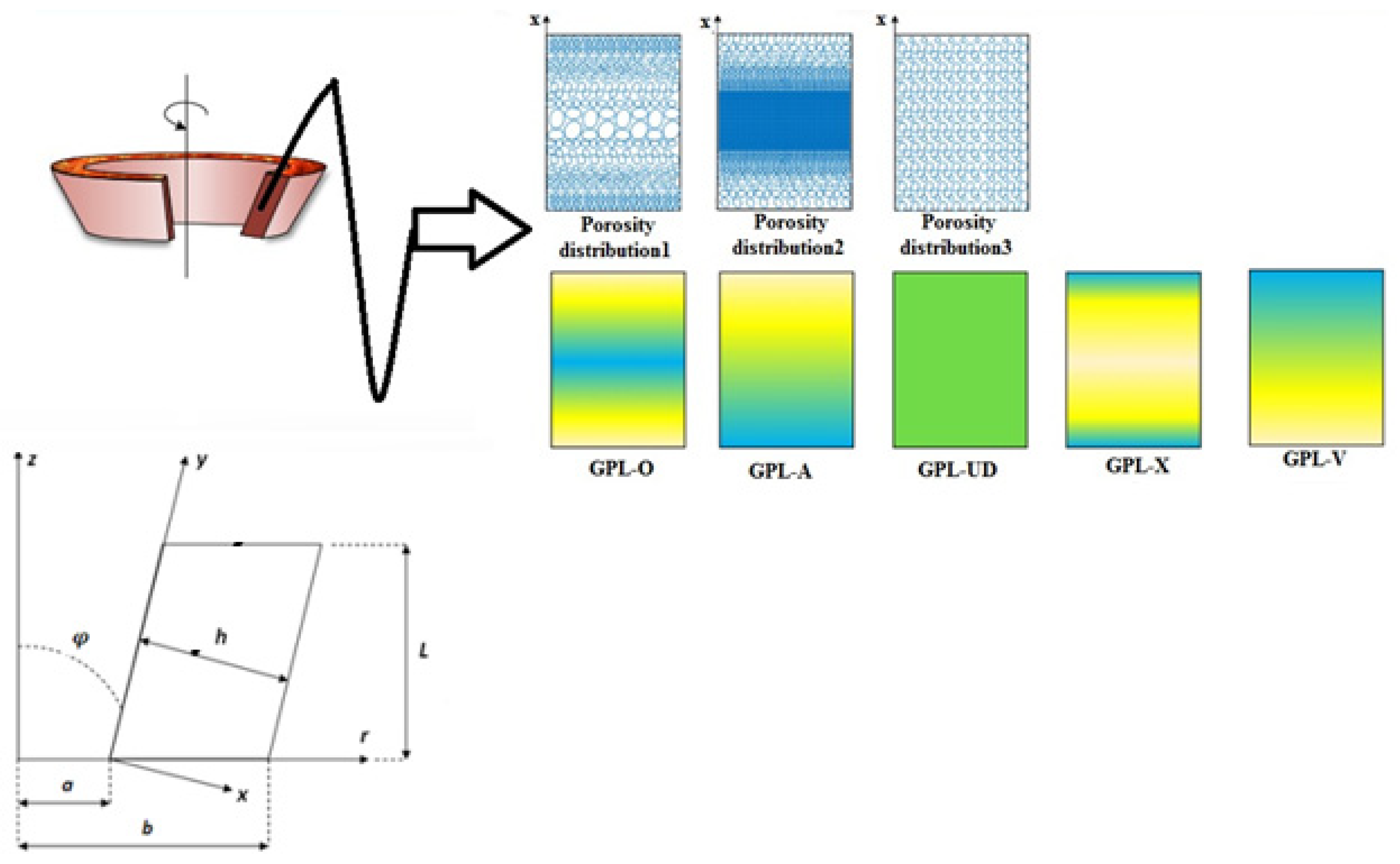
2.1. Geometry Description

Let us consider a FG-GPL porous truncated cone with length L , thickness h (along the x direction, 0 x h ), internal and external radii of the small base a and b , respectively, and semi-vertex angle φ , as depicted in Figure 1. Axisymmetric cylindrical coordinates ( r , z ) are assumed along the radial and axial directions, respectively. Details of porosity distribution and GPL pattern of the structure are also reported in Figure 1.

2.2. Material Properties

Three different porosity distributions are assumed throughout the cone thickness (Figure 1), i.e., two types of non-uniform symmetric distribution and a uniform one. In the first distribution (labeled as I-D1), the porosity is nonlinearly symmetric, with a higher density around the mid-plane rather than the inner and outer surfaces of the cone. In the second distribution (labeled as II-D2), a non-uniform symmetric porosity is assumed, with a higher density near the inner and outer surfaces rather than the mid-plane. For such two cases, the material properties with porosities are defined in Equations (1) and (2), respectively, whereas for a uniform distribution of porosity (labeled as D3) the material properties read as in Equation (3). At the same time, five different GPL patterns are assumed along the cone thickness, as represented in Figure 1 and defined in [43,60]. More specifically:
Porosity distribution 1 (Non-uniform symmetric I-D1)
α ( x ) = α * [ 1 e 0 cos ( π / 2 π x / h ) ] c ( x ) = c * [ 1 e 0 cos ( π / 2 π x / h ) ] k ( x ) = k * [ 1 e 0 cos ( π / 2 π x / h ) ] E ( x ) = E * [ 1 e 0 cos ( π / 2 π x / h ) ] G ( x ) = G * [ 1 e 0 cos ( π / 2 π x / h ) ] ρ ( x ) = ρ * [ 1 e m cos ( π / 2 π x / h ) ]
Porosity distribution 2 (Non-uniform symmetric II-D2)
α ( x ) = α * [ 1 e 0 * ( 1 cos ( π / 2 π x / h ) ) ] c ( x ) = c * [ 1 e 0 * ( 1 cos ( π / 2 π x / h ) ) ] k ( x ) = k * [ 1 e 0 * ( 1 cos ( π / 2 π x / h ) ) ] E ( x ) = E * [ 1 e 0 * ( 1 cos ( π / 2 π x / h ) ) ] G ( x ) = G * [ 1 e 0 * ( 1 cos ( π / 2 π x / h ) ) ] ρ ( x ) = ρ * [ 1 e 0 * ( 1 cos ( π / 2 π x / h ) ) ]
Uniform porosity distribution (D3)
α ( z ) = α * Θ c ( z ) = c * Θ k ( z ) = k * Θ E ( z ) = E * Θ G ( z ) = G * Θ ρ ( z ) = ρ * Θ
The following equations are also applied for evaluating x [61]
x = ( r n r i n ) 2 + ( z n z i n ) 2 r i n = ( tan ( π φ ) r n z n a tan ( π 2 φ ) ) tan ( π φ ) tan ( π 2 φ ) z i n = tan ( π 2 φ ) ( r i n a )
when φ = 0 (cylinder), it is x = r n a , h = b a . In the previous relations, x is the normal space of points through the thickness of the cone from the inner surface; r n and z n refer to the radius and height of an arbitrary point in the domain; r i n and z i n refer to the radius and height of points at the inner surface changing from a to ( a + L tan φ ) and from 0 to L , respectively. Moreover, E ( x ) , G ( x ) , ρ ( x ) , c ( x ) , α ( x ) , k ( x ) stand for the modulus of elasticity, shear stiffness, mass density, specific heat capacity, thermal expansion coefficient, and heat conduction coefficient of the porous nanocomposite cone, respectively. At the same time, E * , G * , ρ * , c * , α * , k * are the similar properties of GPL cone without any porosity. Furthermore, e 0 and e 0 * ( 0 e 0 ( e 0 * ) < 1 ) are the coefficients of porosity belonging to D1 and D2, respectively; e m and e m * stand for the coefficients of mass density related to D1 and D2, respectively; Θ and Θ stand for the variables of a uniform porosity distribution. As the size and density of the internal cavities increase, the porosity increases, leading to a reduction in the material properties. The influence of the material properties of open-cell metal foams [62,63,64] is defined mathematically by Equation (5), from which we can derive the Relation (6) between e 0 and e m , as follows
E ( z ) E * = ( ρ ( z ) ρ * ) 2
{ 1 e m cos ( π 2 π x h ) = 1 e 0 ( π 2 π x h ) 1 e m * ( 1 cos ( π 2 π x h ) ) = 1 e 0 * ( 1 ( π 2 π x h ) ) Θ = Θ
The mass of FG-GPL truncated cone is assumed to be identical, such that
{ 0 h / 2 1 e 0 * ( 1 cos ( π 2 π x h ) ) d x = 0 h / 2 1 e 0 cos ( π 2 π x h ) d x 0 h / 2 Θ d x = 0 h / 2 1 e 0 cos ( π 2 π x h ) d x
here employed to determine e 0 * and Θ for a known value of e 0 . It can be observed that e 0 * rises by enhancing e 0 . When e0 reaches 0.6, e 0 * (=0.9612) is near to the upper bound. This justifies the selection of e 0 ∈ [0, 0.6], as applied hereafter.
Based on a Halpin–Tsai micromechanics model [65], the elasticity modulus for the nanocomposite without porosities E * is defined as
E * = 3 8 ( 1 + ε L G P L η L G P L V G P L 1 η L G P L V G P L ) E m + 5 8 ( 1 + ε W G P L η W G P L V G P L 1 η W G P L V G P L )            
ε L G P L = 2 l G P L t G P L          
ε w G P L = 2 w G P L t G P L          
η L G P L = E G P L E m E G P L + ε L G P L E m
η w G P L = E G P L E m E G P L + ε W G P L E m
where E G P L and E m refer to the elasticity modulus of GPLs and metallic matrix, respectively, l G P L , w G P L , and t G P L refer to the length, width, and thickness of nanofiller platelets, and V G P L is the volume content of GPLs. The rule of mixture [66] is used to compute the mass density, Poisson’s ratio, heat capacitance, heat conductivity coefficient, and heat expansion coefficient of the nanocomposite, namely,
ρ * = ρ G P L V G P L + ρ m ( 1 V G P L )
v * = v G P L V G P L + v m ( 1 V G P L )
c * = c G P L V G P L + c m ( 1 V G P L )            
k * = k G P L V G P L + k m ( 1 V G P L )            
α * = α G P L V G P L + α m ( 1 V G P L )            
where ρ G P L , ρ m , ν G P L , ν m , c G P L , c m , k G P L , k m , α G P L , α m stand for the mass density of GPLs, mass density of metal matrix, Poisson’s ratio of GPLs, Poisson’s ratio of metal matrix, specific heat capacity of GPLs, specific heat capacity of metal matrix, heat conduction coefficient of GPLs, heat conduction coefficient of metal matrix, thermal expansion coefficient of GPLs, thermal expansion coefficient of metal matrix, respectively. Moreover, the Poisson’s ratio is kept constant for open-cell metal foams [67]. The shear modulus G * of the nanocomposite reads as follows
G * = E * 2 ( 1 + v * )
The volume content of GPLs, V G P L , changes across the cone thickness for various dispersion patterns, as follows
V G P L ( z ) = { t i 1 [ 1 cos   ( π 2 π x h ) ]                                         G P L   X t i 2 [ 1 cos   ( π x 2 h ) ]                                                         G P L   A t i 3                                                                                                   G P L   U D t i 4 [ cos   ( π x 2 h ) ]                                                                       G P L   V t i 5 [ sin   ( π x h ) ]                                                                         G P L   O }
where t i 1 , t i 2 , and t i 3 denote the top limit of the V G P L , and i = 1, 2, 3 corresponding to porosity distributions 1, 2, and 3, respectively. V G P L T is estimated by applying the nanofiller weight fraction Δ G P L into Equation (19),
V G P L T = Δ G P L ρ m ρ G P L + Δ G P L ( ρ m ρ G P L )
which is used to derive t i 1 , t i 2 , and t i 3 by the following relation
V G P L T h / 2 h / 2 ρ ( z ) ρ c d x = { t i 1 h / 2 h / 2 [ 1 cos ( π / 2 π x / h ) ] ρ ( z ) ρ c d x t i 2 h / 2 h / 2 [ 1 cos ( π x / 2 h ) ] ρ ( z ) ρ c d x t i 3 h / 2 h / 2 ρ ( z ) ρ c d x t i 4 h / 2 h / 2     [ cos ( π x / 2 h ) ] ρ ( z ) ρ c   d x t i 4 h / 2 h / 2     [ sin ( π x / h ) ] ρ ( z ) ρ c   d x

2.3. Heat Transfer Equation

The heat conduction equation can be defined in axisymmetric cylindrical coordinates as
1 r r   ( r k r ( x ) T r ) + z   ( k z ( x ) T z ) = ρ ( x ) C ( x )   T / t  
where the heat generation rate has been neglected, T is the temperature, and k r ( x ) and k z ( x ) stand for the heat conduction coefficients in the radial and axial direction, respectively.
The thermal boundary conditions are considered as
T ( r , z , 0 ) = T 0
T ( r i n , z , t ) = T 1 = T 0 + T 0 sin ( π z L ) ( 1 exp ( c 0 t ) )
T ( r , 0 , t ) = T ( r , L , t ) = T ( r o u t , z , t ) = T 0
where T 0 refers to the temperature at t = 0 , c 0 is a constant value, r o u t is the radius of points at the external surface that changes from b to b + L tan φ .

2.4. Thermo-Elasticity Equations

Based on a classical linear thermo-elasticity theory, the strain field for an axisymmetric problem reads as follows
[ ε ] = [ ε r r ε θ θ ε z z ε r z ] = [ d ] [ q ]          
with
  [ q ] = { u v } ,                 [ d ] = [ r 0 1 r 0 0 z 1 2 z 1 2 r ]
and u and v refer to the displacement components across the r and z directions, respectively. Moreover, the kinematic relations read as follows [59]
[ σ ] = [ σ r r σ θ θ σ z z τ r z ] = [ D d ] ( [ ε ] [ ε T ] ) ,                         [ ε T ] = α ( x ) Δ T [ 1 1 1 0 ]
where Δ T = T T 0 is the temperature estimated from the heat conduction equation. In addition, [ ε ] stands for the elastic strain and [ ε T ] denotes the thermal strain field stemming from the temperature variation. The elastic stiffness matrix [ D d ] is defined as [68]
[ D d ] = E ( x ) ( 1 + υ ) ( 1 2 υ )   [ 1 υ υ υ 0 υ 1 υ υ 0 υ υ 1 υ 0 0 0 0 1 2 υ 2 ]
The FG-GPL porous truncated cone is simply supported on its two bases, such that the following kinematic boundary conditions are enforced
u ( r , 0 ) = u ( r , L ) = 0

3. Finite Element Modelling

The problem is solved numerically by using the finite element method. In such a context, we approximate the cone in the r z plane of revolution by means of shape functions [ N ( r , z ) d ] ( e ) . Based on a Kantorovich approximation, we define the thermal distribution for each element ( e ) as follows
[ q ] ( e ) = [ N ( r , z ) d ] ( e ) [ δ ] ( e )
T ( r , z , t ) ( e ) = [ N ( r , z ) t ] ( e ) [ T ( t ) ] ( e ) ,         [ N ( r , z ) t ] ( e ) = [ N i   N j   N k     N l   N m   N n ] ,           [ T ( t ) ] ( e ) = [ T ( t ) i T ( t ) j T ( t ) k T ( t ) l T ( t ) m T ( t ) n ]  
  [ N ( r , z ) d ] ( e ) = [ N i 0 N j 0 N k 0 N l 0 N m 0 N n 0 0 N i 0 N j 0 N k 0 N l 0 N m 0 N n ] N i = ( r 23 ( z z 3 ) z 23 ( r r 3 ) ) ( r 46 ( z z 6 ) z 46 ( r r 6 ) ) ( r 23 z 13 z 23 r 13 ) ( r 46 z 16 z 46 r 16 ) N j = ( r 31 ( z z 1 ) z 31 ( r r 1 ) ) ( r 54 ( z z 4 ) z 54 ( r r 4 ) ) ( r 31 z 21 z 31 r 21 ) ( r 54 z 24 z 54 r 24 )   N k = ( r 21 ( z z 1 ) z 21 ( r r 1 ) ) ( r 56 ( z z 6 ) z 56 ( r r 6 ) ) ( r 21 z 31 z 21 r 31 ) ( r 56 z 36 z 56 r 36 ) N l = ( r 31 ( z z 1 ) z 31 ( r r 1 ) ) ( r 23 ( z z 3 ) z 23 ( r r 3 ) ) ( r 31 z 41 z 31 r 41 ) ( r 23 z 43 z 23 r 43 ) N m = ( r 31 ( z z 1 ) z 31 ( r r 1 ) ) ( r 21 ( z z 1 ) z 21 ( r r 1 ) ) ( r 31 z 51 z 31 r 51 ) ( r 21 z 51 z 21 r 51 ) N n = ( r 21 ( z z 1 ) z 21 ( r r 1 ) ) ( r 23 ( z z 3 ) z 23 ( r r 3 ) ) ( r 21 z 61 z 21 r 61 ) ( r 23 z 63 z 23 r 63 ) [ δ ] ( e ) = [ u i       v i       u j       v j       u k       v k       u l       v l       u m       v m       u n       v n ] T
The indexes d and t refer to the structural and thermal solutions of the problem, respectively. By substitution of Equation (31) into Equation (26), the elastic strain matrix for the arbitrary element ( e ) can be defined as
[ ε ] ( e ) = [ B d ] ( e ) [ δ ] ( e )
where [ B d ] ( e ) = [ d ] [ N ( r , z ) d ] ( e ) , or more specifically
[ B d ] = [ N 1 r 0 N 2 r 0 N 3 r 0 N 4 r 0 N 5 r 0 N 6 r 0 1 r N 1 0 1 r N 2 0 1 r N 3 0 1 r N 4 0 1 r N 5 0 1 r N 6 0 0 N 1 z 0 N 2 z 0 N 3 z 0 N 4 z 0 N 5 z 0 N 6 z 1 2 N 1 z 1 2 N 1 r 1 2 N 2 z 1 2 N 2 r 1 2 N 3 z 1 2 N 3 r 1 2 N 4 z 1 2 N 4 r 1 2 N 5 z 1 2 N 5 r 1 2 N 6 z 1 2 N 6 r ]
Note that matrix [ N ( r , z ) ] ( e ) refers to the second-order interpolation functions in terms of its nodal values for element (e), and [ T ( t ) ] denotes the corresponding nodal temperature vector. In addition to the displacement components, the inhomogeneity of the material properties of the FG-GPL porous cone can be expressed by means of their nodal values as follows
E = i = 1 6 E i   N i = E ^
ρ = i = 1 6 ρ i   N i = ρ ^
c = i = 1 6 c i   N i = C ^
α = i = 1 6 α i   N i = α ^  
k = i = 1 6 k i   N i = K ^
where E i , ρ i , c i , α i , k i refer to the elasticity modulus, mass density, specific heat capacity, thermal expansion coefficient, and heat conduction coefficient related to the arbitrary node i . Moreover, , E ^ , ρ ^ , C ^ , α ^ , and k ^ refer to the shape functions vector, elasticity modulus, mass density, heat capacity, heat expansion coefficient, and heat conductivity coefficient for each element, defined as
= [ N 1                 N 6 ] ,         E ^ = [ E 1                 E 6 ] T ,         ρ ^ = [ ρ 1                 ρ 6 ] T C ^ = [ C 1                 C 6 ] T ,         α ^ = [ α 1                 α 6 ] T ,         k ^ = [ k 1                 k 6 ] T
By a mathematical manipulation, Equation (22) can be simplified as
I = V 1 2 [ 2 ( Q ρ C T t ) T + r k r ( T r ) 2 + r k z ( T z ) 2 ] d V + S 1 q " T d S + S 2 1 2 h ( T T ) 2 d S
where V is the volume, S 1 and S 2 are the boundary surfaces of the cone, q , Q ,   T , and h stand for the heat flux, rate of energy generation per unit volume, surrounding temperature, and heat convection coefficient, respectively.
According to FEM, we redefine Equation (42), in a variational form [69], to yield the following expression for capacitance [ K 1 t ] ( e ) , stiffness [ K 2 t ] ( e ) and [ K 3 t ] ( e ) , and force [ F t ] matrices for each element ( e )
[ K 1 t ] ( e ) = V ( e ) ρ ( x ) C ( x ) [ N t ] T [ N t ] d V = V ( e ) ( ρ ^ ) ( C ^ ) [ N t ] T [ N t ] d V
[ K 2 t ] ( e ) = V ( e ) [ B t ] T [ D ( x ) t ] [ B t ]   d V
where
[ D ( x ) t ] = [ r k r ( x ) 0 0 r k z ( x ) ] = [ r ( K ^ r ) 0 0 r ( K ^ z ) ]                
[ B t ] = [ N i r N j r N k r N l r N m r N n r N i z N j z N k z N l z N m z N n z ]
[ K 3 t ] ( e ) = S ( e ) h   [ N t ] T [ N t ] d S
[ F t ] ( e ) = V ( e ) Q [ N t ] T d V S 1 ( e ) q " [ N t ] T d S + S 2 ( e ) h T [ N t ] T d S
in which V ( e ) denotes the volume element, S 1 ( e ) and S 2 ( e ) refer to the boundary elements subjected to a heat flux and heat convection, respectively. By assembling the element matrices, the global heat transfer takes the following form
[ K 1 t ] [ θ ˙ ] + ( [ K 2 t ] + [ K 3 t ] ) [ θ ] = [ F t ]
An unconditionally stable scheme based on a Crank–Nicolson time stepping procedure is thus applied for numerically solving the differential Equation (49), under a suitable time step selection, see Ref. [70]. More details about the algorithm are provided in Appendix A. Once deriving the transient temperature distribution, we solve the thermoelastic problem, while using simplex linear triangular elements to approximate the kinematic field. Based on a Rayleigh–Ritz energy formulation, the structural stiffness and force element matrices owing to a varying temperature and rotational velocity are, thus, obtained as
[ K d ] ( e ) = V ( e )   [ B d ] T [ D d ] [ B d ] d V
[ F d ] ( e ) = V ( e )   [ B d ] [ D d ] [ ε T ]   d V + A ( e ) N T Γ d V [ ε T ] = ( ) Δ T [ 1         1         1         0 ] T [ D d ] = ( Ξ ) ( 1 + υ ) ( 1 2 υ )   [ 1 υ υ υ 0 υ 1 υ υ 0 υ υ 1 υ 0 0 0 0 1 2 υ 2 ]
    Γ = [ Γ r 0 ]
The first term in (51) is the force due to a thermal variation and the second term is that one due to a rotational velocity; moreover, Γ r defines the body force component in the r direction
Γ r = ρ r ω 2
whereas the governing equations of the problem take the following matrix form
[ K d ] [ Δ ] = { F d }
This equation must be solved at each time step with the known temperature variation as derived from Equation (49).

4. Results and Discussion
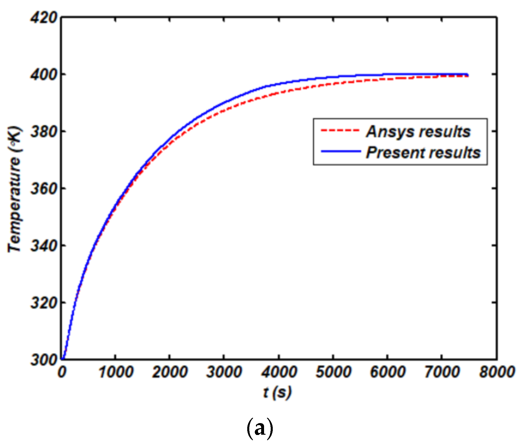
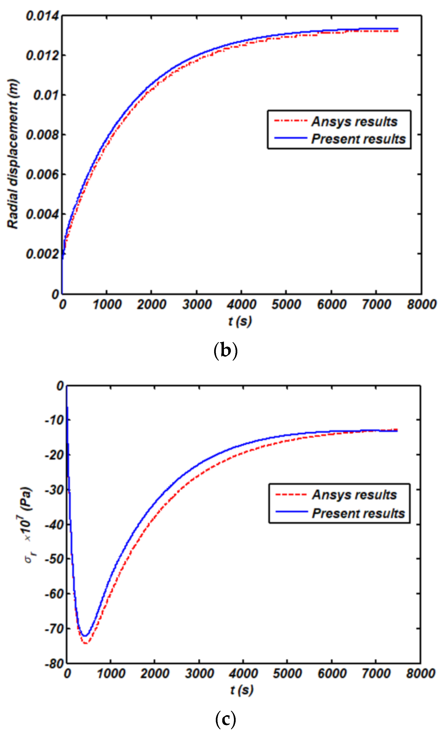
4.1. Verification

In this section we present the results from a transient stress analysis for a simply-supported FG-GPL porous rotating truncated cone, defined geometrically by a = 1 , b = 1.5 , L = 2 , φ = 15 ° , and ω = 100   rad / s . The selected structural member is made of a homogenous material with the following thermo-mechanical properties: E = 198.8   GPa , ρ = 8340   kg / m 3 , ν = 0.33 , k = 512   W / ( m k ) , C = 876   j / ( Kg k ) , α = 7.74 × 10 5   1 / k , while the thermal boundary conditions are enforced for T 0 = 300 ° k , T 1 = 600 ° k . Our numerical results are compared to those ones from the commercial FEM software ANSYS Workbench, in terms of thermal time history, radial displacement, radial stress state at the midpoint of the cone, under the assumptions γ G P L = 0 % and e 0 = 0 , e m = 0 (see Figure 2). To model the problem in ANSYS Workbench, quadratic quadrilateral elements have been used for the sake of accuracy, under the assumption of 2D axisymmetric elasticity like in the present study. To get convergent results, the time step has been set equal to 1 s, and 20 × 30 elements have been considered along the radial and axial directions. As visible from all the plots in Figure 2, our results match perfectly with predictions from the ANSYS code, thus confirming the reliability and accuracy of the proposed FEM-based formulation to treat the selected thermomechanical problem. All the time histories in Figure 2 refer to the center point of the cone, whose temperature (Figure 2a) and radial displacement (Figure 2b) feature a smooth and monotonic increase up to a plateau value, while observing a non-monotonic variation in the compressive stress state (Figure 2c) with a rapid increase up to the maximum value in a short time-lapse, followed by a gradual decrease up to a plateau value.

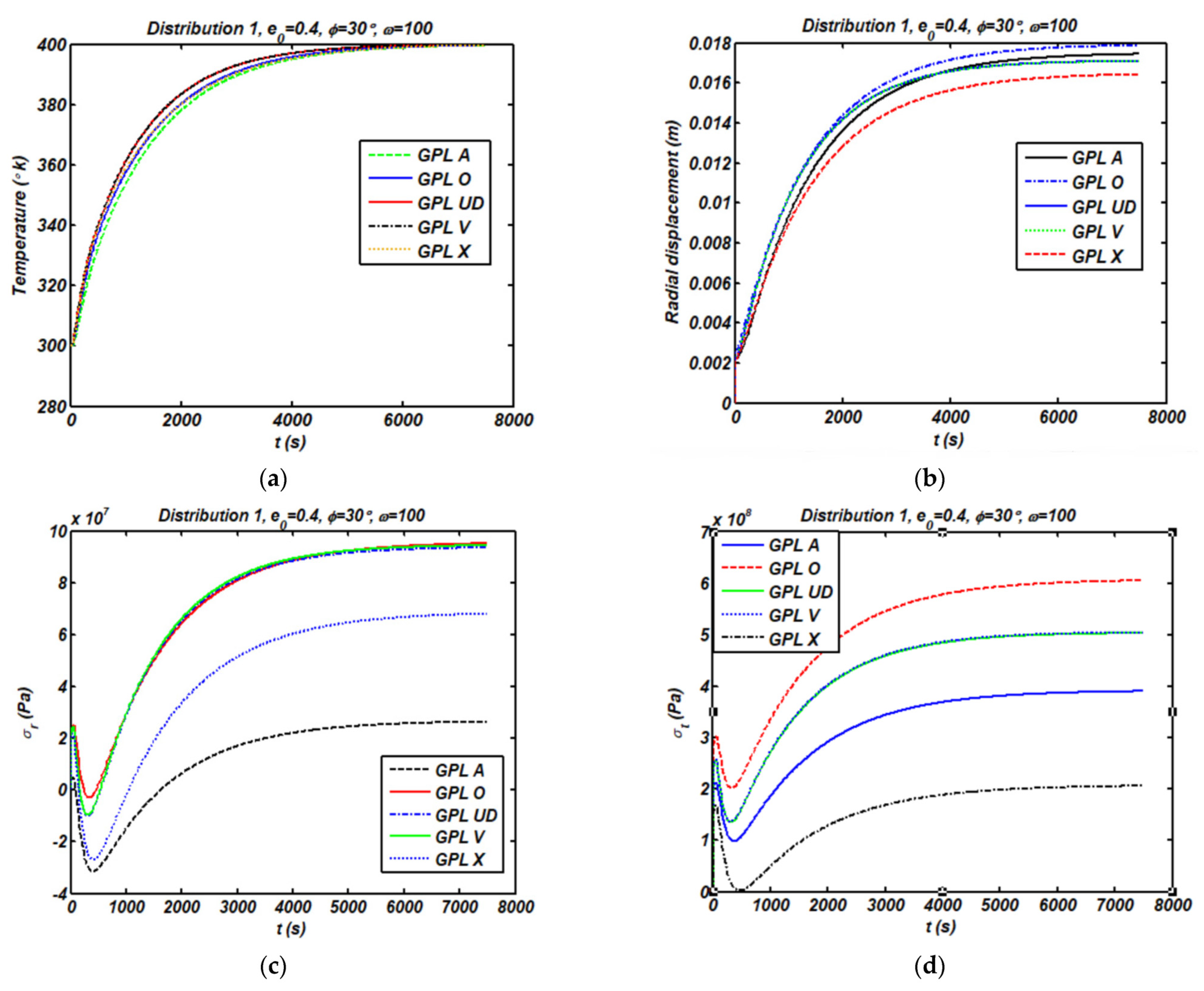
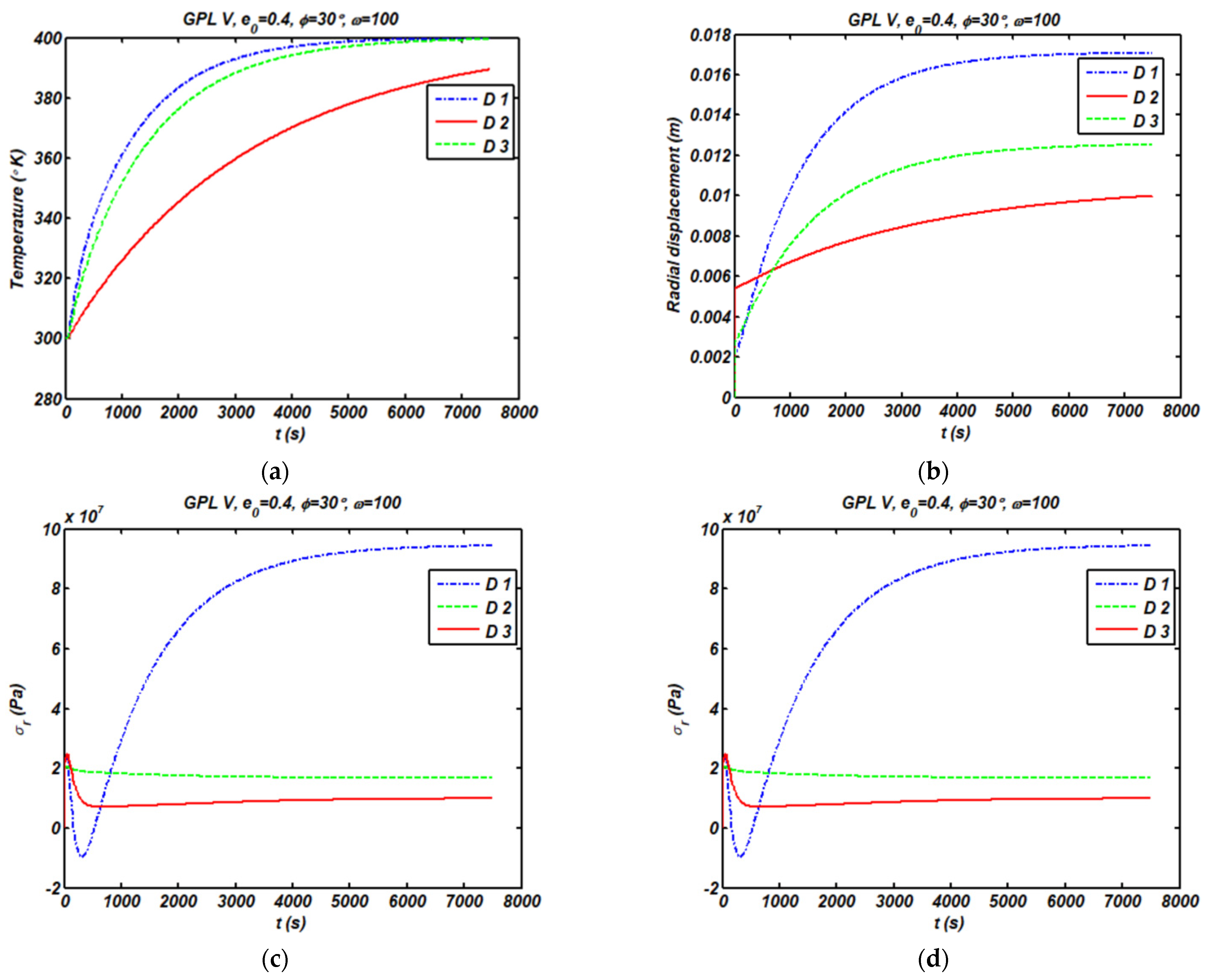
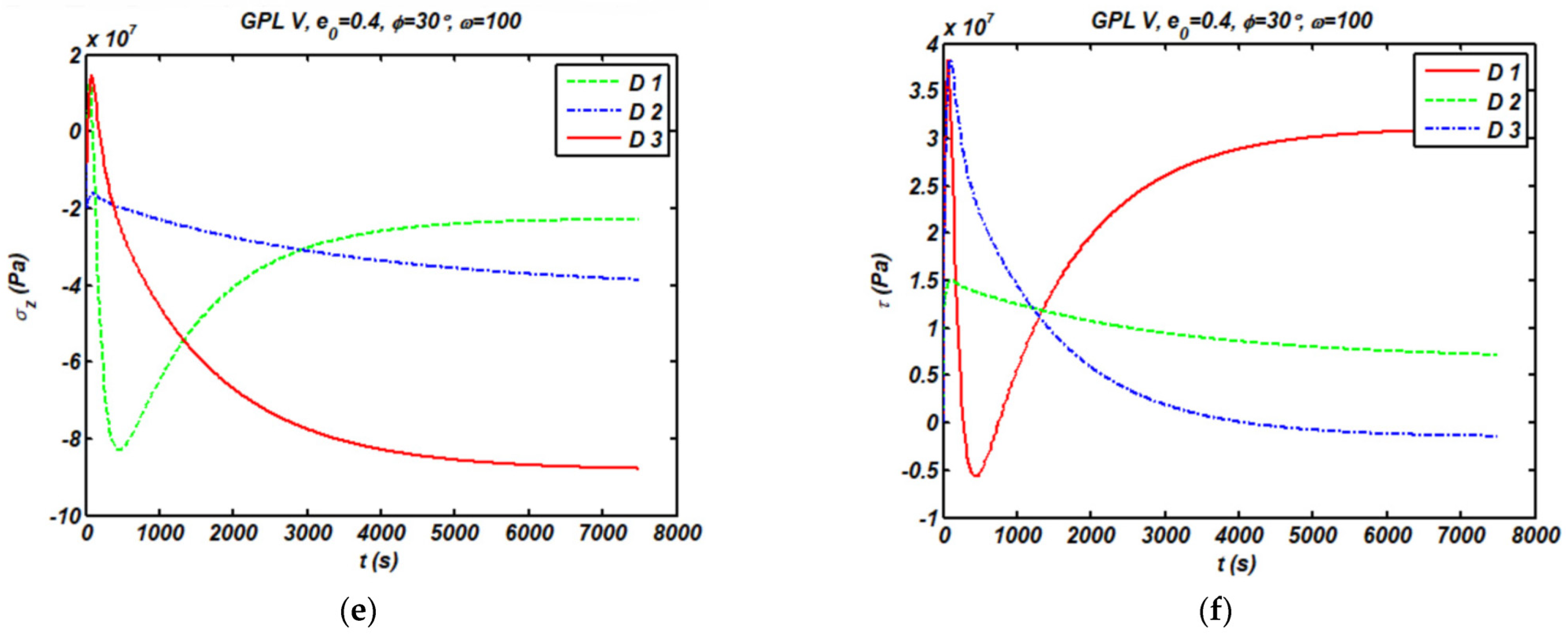
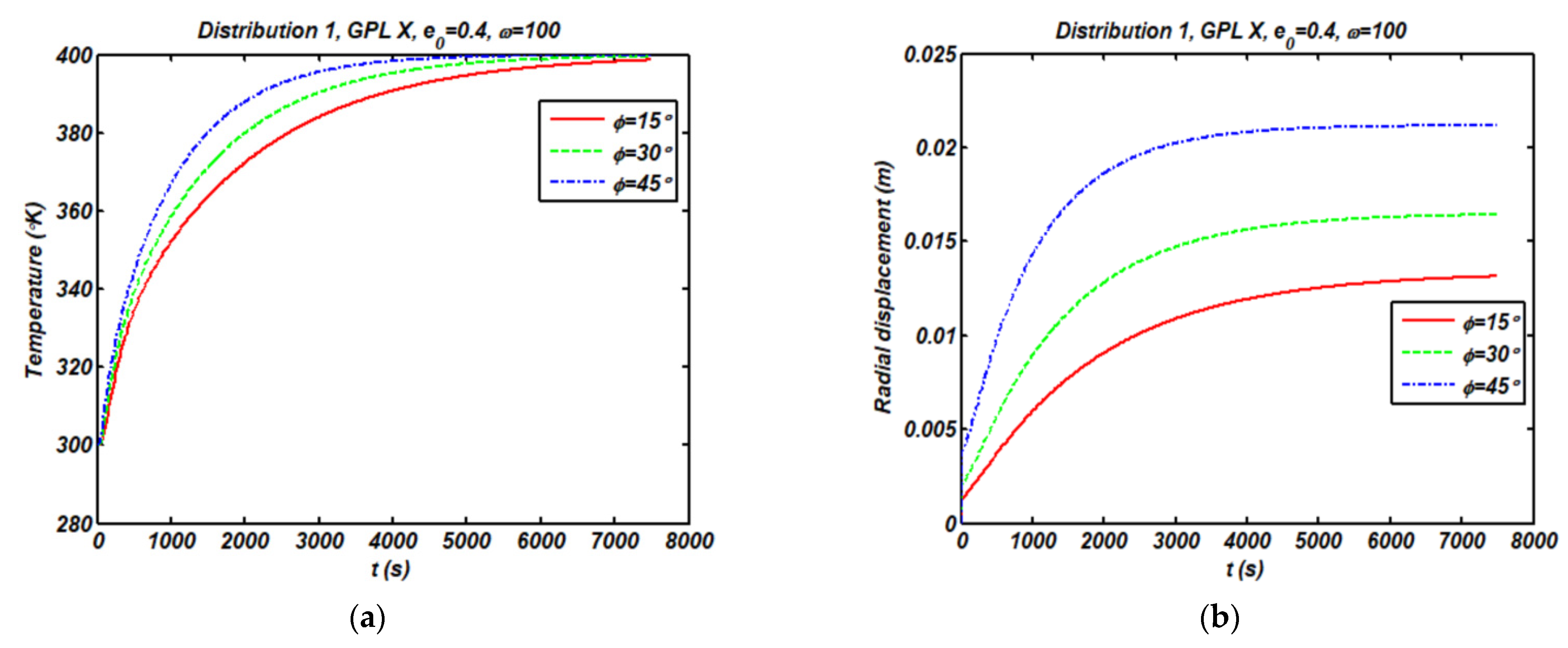
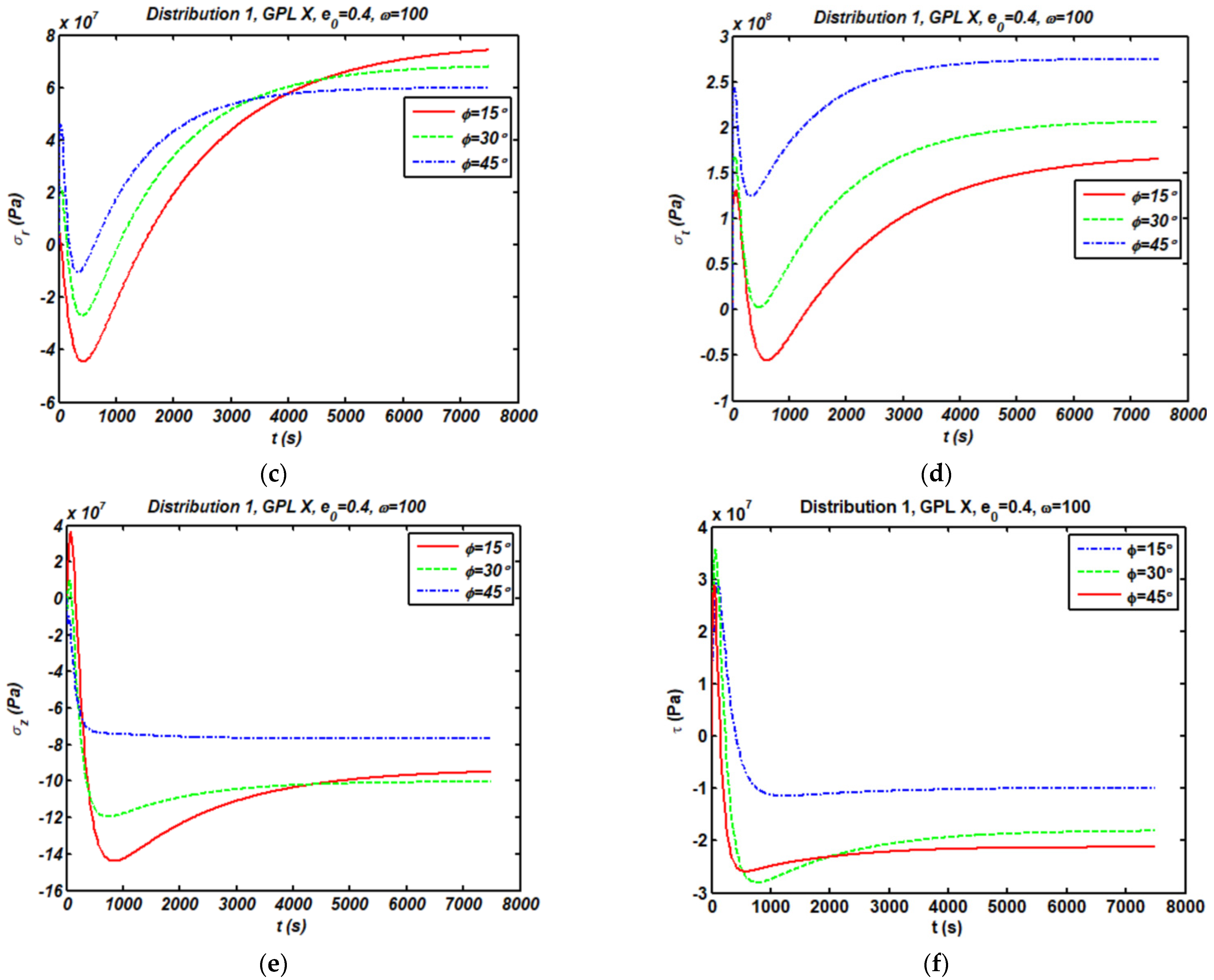
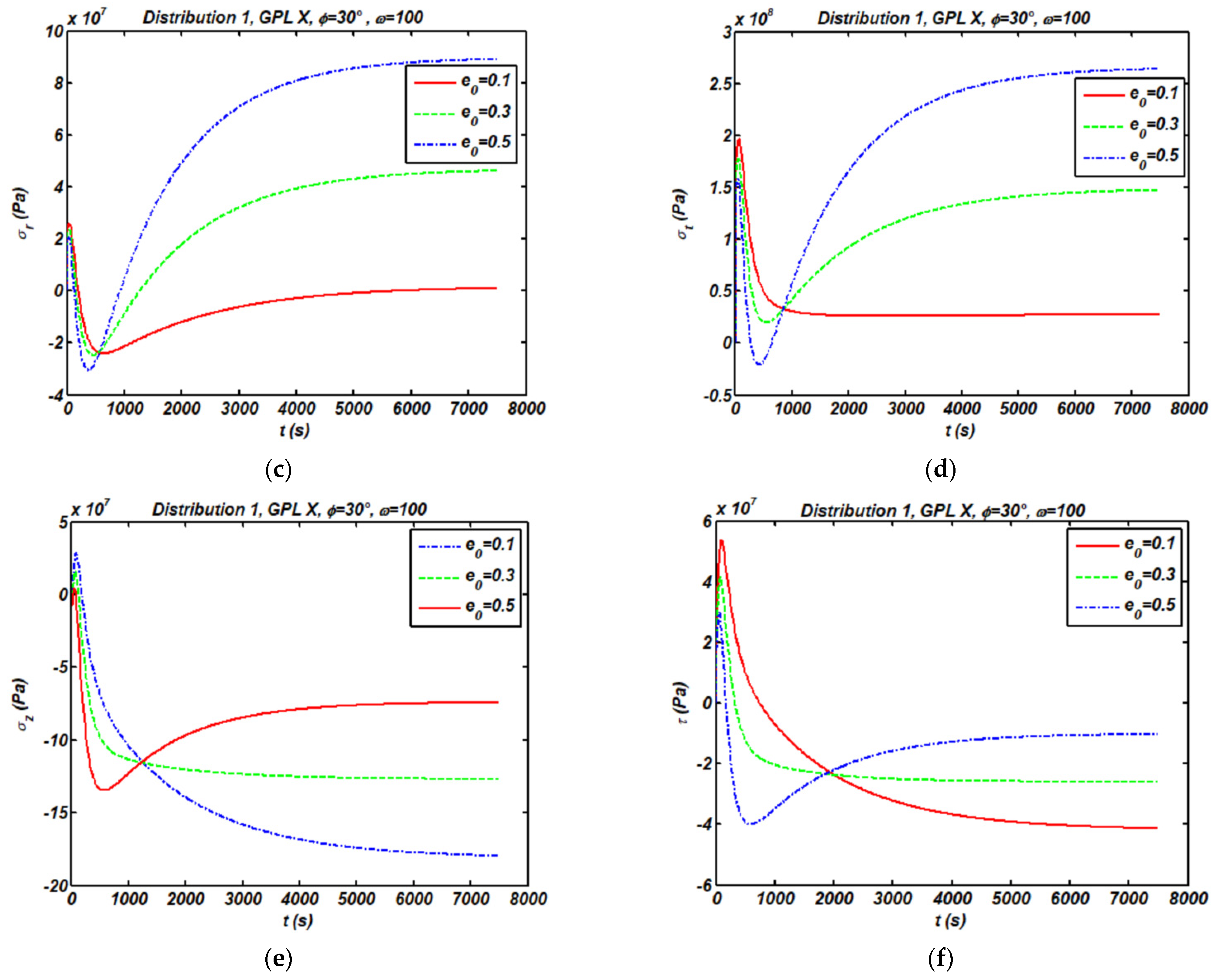
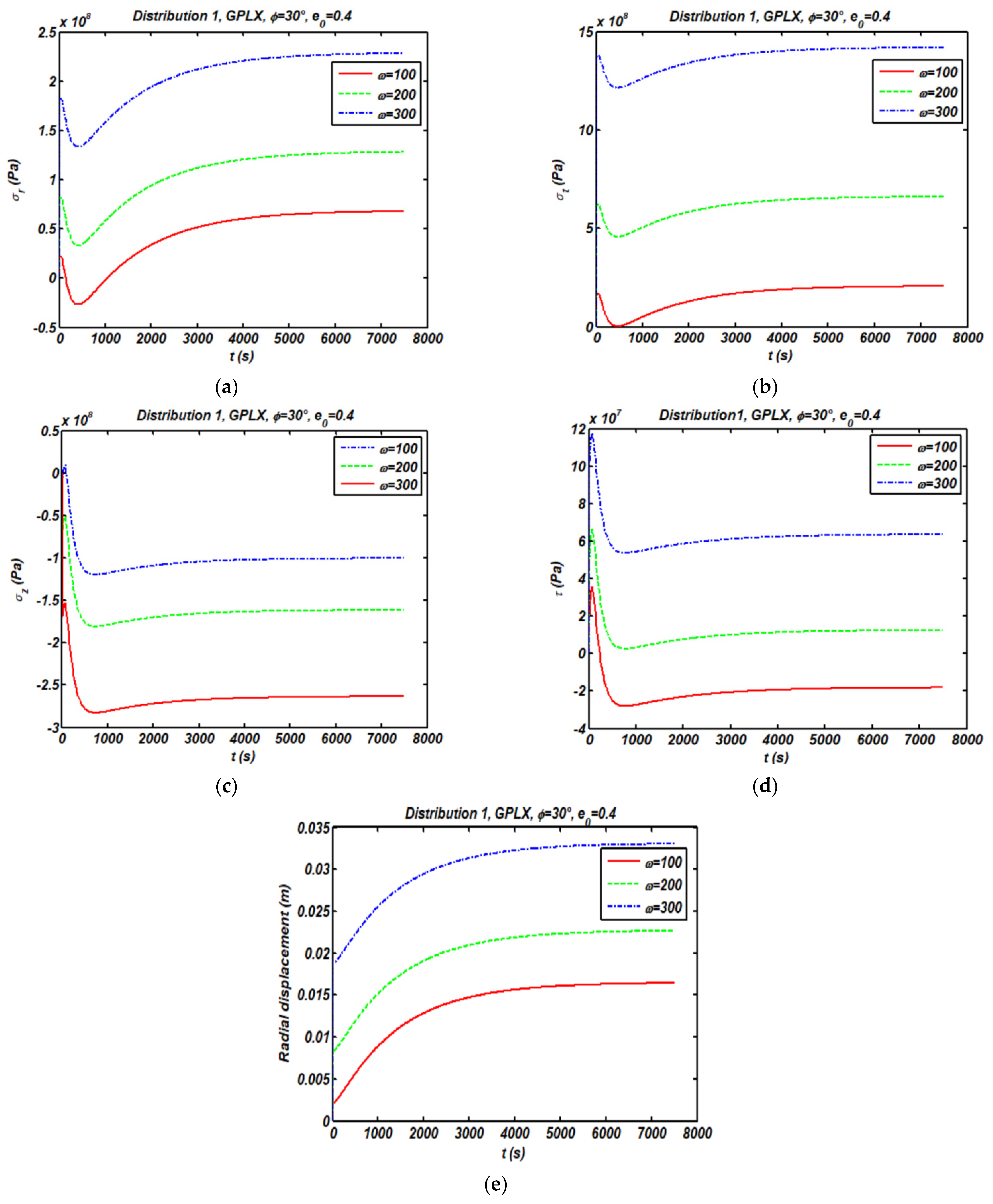
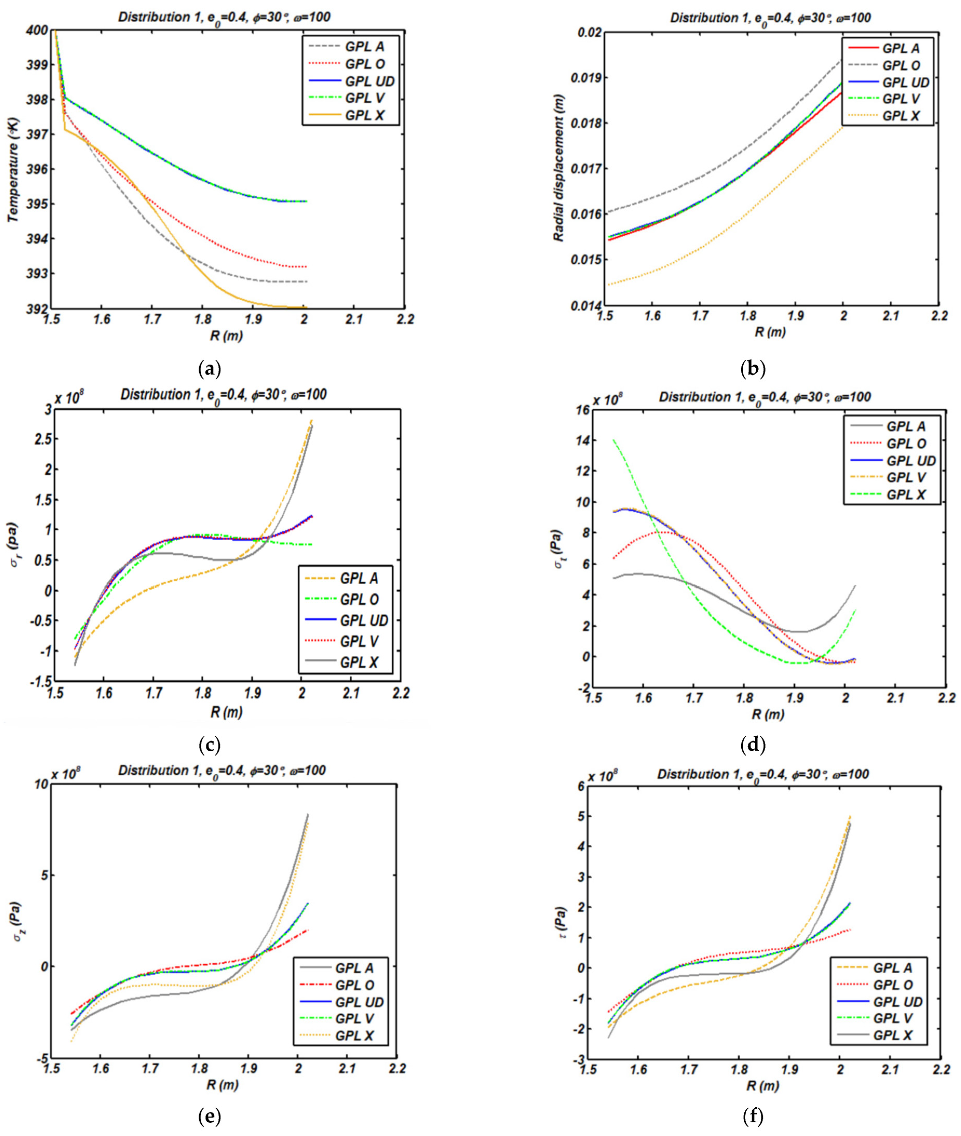
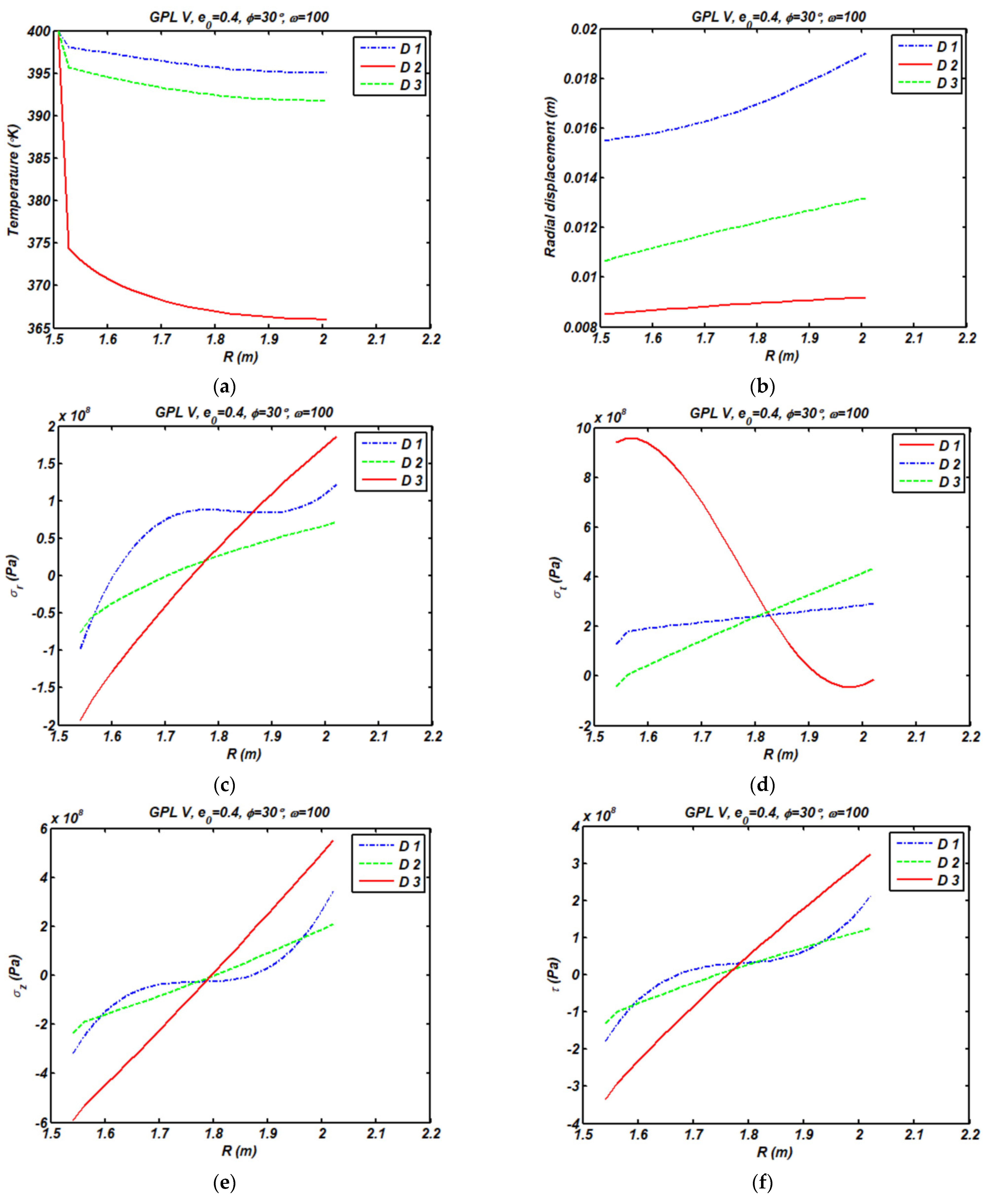
4.2. Transient and Steady Responses

The study continuous with the analysis of the transient thermal response of a FG-GPL porous rotating truncated cone, with material properties in Table 1 for both GPLs and metal matrix. As plotted in Figure 3, a systematic study checks for the influence of the GPL pattern on the thermal time history (Figure 3a), radial displacement (Figure 3b), and stress state (Figure 3c–e) for the centered point of the selected truncated cone. Hereafter, the stress state [ σ ] T = [ σ r r     σ θ θ     σ z z     τ r z ] T will be labeled as [ σ ] T = [ σ r     σ t     σ z     τ ] T for simplicity reasons. Based on the plots in Figure 3, the effect of the GPL pattern is much more pronounced on the transient thermal and kinematic response compared to the stress one. More specifically, it is worth observing that the temperature response maintains almost the same for a GPLUD and GPLV distribution. At the same time, GPLUD, GPLV, and GPLO patterns yield the same effect on the radial stress response. Besides, the effect of GPLUD and GPLV patterns on the other stress components seems almost the same. The results also denote that the maximum and minimum compressive axial and radial stress is reached for a GPLA and GPLO, respectively. In addition, the maximum and minimum steady state of radial, axial, and shear stresses belongs to a GPLO and GPLA distribution, respectively, while the maximum and minimum steady state of tangential stress and radial displacement belongs to a GPLO and GPLX distribution. Figure 4 indicates the influence of porosity distribution on the time history of temperature (Figure 4a), radial displacement (Figure 4b), and stresses (Figure 4c–e) for the central point of the truncated cone. The results show that the temperature and displacement field will be steady sooner for D1, and the maximum and minimum magnitude of steady state temperature and displacement belongs to D1 and D3, respectively. It is interesting to note that the distribution of porosity has a meaningful effect on the radial and tangential stress time histories, which, in turn, show a relaxation for a D1 porosity, since they change from a compressive to a traction state.
In Figure 5 we also plot the geometrical effect of a semi-vertex angle on the time history of temperature (Figure 5a), radial displacement (Figure 5b), and stresses (Figure 5c–e) at the central point of the truncated cone. It can be seen that, by increasing a semi-vertex angle, the cone behavior will be steady sooner. Figure 6 also shows the effect of the porosity coefficient on the same time histories for the same central point of the selected structure. It is worth observing that an increased porosity coefficient yields an increased steady state radial displacement and stress field. Structures with higher levels of porosity will respond more quickly to a thermal variation and reach the equilibrium conditions in a faster way.
Figure 7 also analyzes the sensitivity of the response for different weight fractions of nanofillers. While the weight fraction of nanofillers increases, the steady state response significantly decreases due to an increased structural stiffness. For higher weight fractions of nanofillers, indeed, the structure will be steady faster. As also plotted in Figure 8, we repeat the same systematic analysis for a varying circular velocity, where it is clearly evident that an increased circular velocity causes an increased steady state stress field (Figure 8a–d) and radial displacement (Figure 8e).
The influence of various GPL patterns on temperature, radial displacement, and stresses along the r direction (at z = L / 2 ) is depicted in Figure 9. Note that the effect of a GPLV and GPLUD pattern on the overall thermo-mechanical response is quite similar. As also plotted in Figure 10, for different porosity patterns, the D1, D3, and D2 patterns provide a higher level of temperature and radial displacement, respectively. The effect of D1 on the radial stress state is nonlinear, while D3 and D2 provide almost a linear distribution in the radial direction. The influence of the porosity coefficient on temperature, radial displacement, and stresses along the r–direction at z = L / 2 is shown in Figure 11. As expected, by increasing the porosity coefficient, the radial displacement increases, owing the structure to achieve a lower stiffness. At the same time, the temperature increases for an increased porosity level in the structure; see also the final contour plots in Figure 12 for the radial, axial, tangential, and shear stresses in Figure 12 in the steady state situation.

5. Conclusions

This work focused on the transient thermal stress response of porous rotating truncated cones reinforced by GPLs based on a classical linear thermos-elasticity. A finite element approach based on a Rayleigh–Ritz formulation and Crank–Nicolson time-stepping algorithm was employed to model and solve the problem, while checking for the influence of the porosity coefficient and distributions, GPL dispersion pattern, weight fraction of nanofillers, semi vertex angle, and rotational velocity, on the transient temperature, radial displacement, and stress state of the structure. Based on a large systematic investigation, it seems that GPLUD and GPLV distributions of GPLs provide almost the same temperature response. In addition, GPLUD, GPLV, and GPLO patterns have the same effect on the radial stress response. Besides, the effect of GPLUD and GPLV patterns on the other stress components seems almost the same. Results denote that the maximum and minimum compressive axial and radial stress state is reached for a GPLA and GPLO, respectively. Moreover, the maximum and minimum steady state for the radial, axial, and shear stresses correspond to GPLO and GPLA, respectively, while the maximum and minimum steady state of tangential stress and radial displacement is reached for a GPLO and GPLX distribution. The temperature and displacement response will be steady sooner for a D1 porosity, and the maximum and minimum magnitude of steady state temperature and displacement correspond to a D1 and D3 porosity, respectively.
The distribution of porosity has a meaningful effect on the stress time histories. More specifically, a D1 porosity gets a relaxation in the stress state, since the nature of radial and tangential stresses changes from a compressive to a tensional state. Moreover, the influence of a D1 porosity on the radial stress state is nonlinear, while a D3 and D2 porosity features almost a linear distribution throughout the radial direction.
For an increased semi-vertex angle, the cone behavior will be steady sooner. The steady state radial displacement and stress field increases for an increased porosity coefficient. A conic structure with an increased amount of porosity will also react more quickly to a thermal condition variation, reaching a faster equilibrium condition. For an increased weight fraction of GPLs, the steady state radial displacement significantly decreases, and the structure becomes steady faster. At the same time, conic structures with an increased circular velocity feature an increased steady state radial displacement and stress field. The present findings could serve as theoretical predictions for design purposes of high-speed centrifugal separators, gas turbines, or high-power aircraft jet engines.

Author Contributions

Conceptualization, R.D. and F.T.; Data curation, R.D. and F.T.; Formal analysis, M.B., F.K., K.A., R.D. and F.T.; Investigation, M.B., F.K., K.A., R.D. and F.T.; Methodology, R.D. and F.T.; Supervision, R.D. and F.T.; Validation, R.D. and F.T.; writing—original draft, M.B., F.K. and K.A.; writing—review & editing, R.D. and F.T. All authors have read and agreed to the published version of the manuscript.

Funding

This research received no external funding.

Conflicts of Interest

The authors declare no conflict of interest.

Appendix A

The direct integration method may be used to integrate Equation (49) in time domain. Two states of { θ } separated by time increment Δ t denoted by { θ } t and { θ } t + Δ t are considered. According to the trapezoidal rule, the two vectors are related as
{ θ } t + Δ t = { θ } t + [ ( 1 β ) { θ } ˙ t + β { θ } ˙ t + Δ t ] Δ t
where β is a constant which may be selected by the analyst. Equation (49) is written at times t and t + Δ t , the first equation is multiplied by ( 1 β ) and the second equation is multiplied by β to give
( 1 β ) ( [ K 1 t ] { θ } ˙ t + [ K 2 t + K 3 t ] { θ } t ) = ( 1 β ) { F t } t
β ( [ K 1 t ] { θ } ˙ t + Δ t + [ K ] { θ } t + Δ t ) = β { F t } t + Δ t
These two equations are added and Equation (A1) is used to eliminate the time derivatives of { θ } . The resulting equation is solved for { θ } t + Δ t , which yields
( 1 Δ t [ K 1 t ] + β [ K 2 t + K 3 t ] ) { θ } t + Δ t = ( 1 Δ t [ K 1 t ] ( 1 β ) [ K 2 t + K 3 t ] ) { θ } t + ( 1 β ) { F } t + β { F t } t + Δ t
For β = 1 2 , we obtain the Crank–Nicolson algorithm, which is unconditionally stable, regardless of the value of Δ t .

References

  1. Smith, B.H.; Szyniszewski, S.; Hajjar, J.F.; Schafer, B.W.; Arwade, S.R. Steel foam for structures: A review of applications, manufacturing and material properties. J. Constr. Steel Res. 2012, 71, 1–10. [Google Scholar] [CrossRef] [Green Version]
  2. Lefebvre, L.P.; Banhart, J.; Dunand, D.C. Porous metals and metallic foams: Current status and recent developments. Adv. Eng. Mater. 2008, 10, 775–787. [Google Scholar] [CrossRef] [Green Version]
  3. Xia, X.C.; Chen, X.W.; Zhang, Z.; Chen, X.; Zhao, W.M.; Liao, B.; Hur, B. Effects of porosity and pore size on the compressive properties of closed-cell Mg alloy foam. J. Magnes. Alloys 2013, 1, 330–335. [Google Scholar] [CrossRef] [Green Version]
  4. Wang, Y.; Wu, D. Free vibration of functionally graded porous cylindrical shell using a sinusoidal shear deformation theory. Aerosp. Sci. Technol. 2017, 66, 83–91. [Google Scholar] [CrossRef]
  5. Babaei, M.; Asemi, K.; Kiarasi, F. Static response and free-vibration analysis of a functionally graded annular elliptical sector plate made of saturated porous material based on 3D finite element method. Mech. Based Des. Struct. Mach. 2020, 1–25. [Google Scholar] [CrossRef]
  6. Iijima, S. Helical microtubules of graphitic carbon. Nature 1991, 354, 56–58. [Google Scholar] [CrossRef]
  7. Liew, K.M.; Lei, Z.X.; Zhang, L.W. Mechanical analysis of functionally graded carbon nanotube reinforced composites: A review. Compos. Struct. 2015, 120, 90–97. [Google Scholar] [CrossRef]
  8. Babaei, M.; Asemi, K. Static, dynamic and natural frequency analyses of functionally graded carbon nanotube annular sector plates resting on viscoelastic foundation. SN Appl. Sci. 2020, 2, 1652. [Google Scholar] [CrossRef]
  9. Mittal, G.; Dhand, V.; Rhee, K.Y.; Park, S.J.; Lee, W.R. A review on carbon nanotubes and graphene as fillers in reinforced polymer nanocomposites. J. Ind. Eng. Chem. 2015, 21, 11–25. [Google Scholar] [CrossRef]
  10. Duarte, I.; Ventura, E.; Olhero, S.; Ferreira, J.M. An effective approach to reinforced closed-cell Al-alloy foams with multiwalled carbon nanotubes. Carbon 2015, 95, 589–600. [Google Scholar] [CrossRef]
  11. Rafiee, M.A.; Rafiee, J.; Wang, Z.; Song, H.; Yu, Z.Z.; Koratkar, N. Enhanced mechanical properties of nanocomposites at low graphene content. ACS Nano 2009, 3, 3884–3890. [Google Scholar] [CrossRef] [PubMed]
  12. Hassani, A.; Habibolahzadeh, A.; Bafti, H. Production of graded aluminum foams via powder space holder technique. Mater. Des. 2012, 40, 510–515. [Google Scholar] [CrossRef]
  13. Chen, D.; Yang, J.; Kitipornchai, S. Nonlinear vibration and postbuckling of functionally graded graphene reinforced porous nanocomposite beams. Compos. Sci. Technol. 2017, 142, 235–245. [Google Scholar] [CrossRef] [Green Version]
  14. Kitipornchai, S.; Chen, D.; Yang, J. Free vibration and elastic buckling of functionally graded porous beams reinforced by graphene platelets. Mater. Des. 2017, 116, 656–665. [Google Scholar] [CrossRef]
  15. Yang, J.; Chen, D.; Kitipornchai, S. Buckling and free vibration analyses of functionally graded graphene reinforced porous nanocomposite plates based on Chebyshev-Ritz method. Compos. Struct. 2018, 193, 281–294. [Google Scholar] [CrossRef]
  16. Gao, K.; Gao, W.; Chen, D.; Yang, J. Nonlinear free vibration of functionally graded graphene platelets reinforced porous nanocomposite plates resting on elastic foundation. Compos. Struct. 2018, 204, 831–846. [Google Scholar] [CrossRef]
  17. Rezaiee-Pajand, M.; Sobhani, E.; Masoodi, A.R. Free vibration analysis of functionally graded hybrid matrix/fiber nanocomposite conical shells using multiscale method. Aerosp. Sci. Technol. 2020, 105, 105998. [Google Scholar] [CrossRef]
  18. Safarpour, M.; Rahimi, A.R.; Alibeigloo, A. Static and free vibration analysis of graphene platelets reinforced composite truncated conical shell, cylindrical shell, and annular plate using theory of elasticity and DQM. Mech. Based Des. Struct. Mach. 2020, 48, 496–524. [Google Scholar] [CrossRef]
  19. Al-Furjan, M.S.H.; Habibi, M.; Ghabussi, A.; Safarpour, H.; Safarpour, M.; Tounsi, A. Non-polynomial framework for stress and strain response of the FG-GPLRC disk using three-dimensional refined higher-order theory. Eng. Struct. 2021, 228, 111496. [Google Scholar] [CrossRef]
  20. Rezaiee-Pajand, M.; Sobhani, E.; Masoodi, A.R. Semi-analytical vibrational analysis of functionally graded carbon nanotubes coupled conical-conical shells. Thin Walled Struct. 2021, 159, 107272. [Google Scholar] [CrossRef]
  21. Safarpour, M.; Forooghi, A.; Dimitri, R.; Tornabene, F. Theoretical and numerical solution for the bending and frequency response of graphene reinforced nanocomposite rectangular plates. Appl. Sci. 2021, 11, 6331. [Google Scholar] [CrossRef]
  22. Sobhani, E.; Masoodi, A.R.; Ahmadi-Pari, A.R. Vibration of FG-CNT and FG-GNP sandwich composite coupled Conical-Cylindrical-Conical shell. Compos. Struct. 2021, 273, 114281. [Google Scholar] [CrossRef]
  23. Sobhani, E.; Masoodi, A.R.; Civalek, O.; Ahmadi-Pari, A.R. Agglomerated impact of CNT vs. GNP nanofillers on hybridization of polymer matrix for vibration of coupled hemispherical-conical-conical shells. Aerosp. Sci. Technol. 2021, 120, 107257. [Google Scholar] [CrossRef]
  24. Sobhani, E.; Masoodi, A.R. Natural frequency responses of hybrid polymer/carbon fiber/FG-GNP nanocomposites paraboloidal and hyperboloidal shells based on multiscale approaches. Aerosp. Sci. Technol. 2021, 119, 107111. [Google Scholar] [CrossRef]
  25. Sobhani, E.; Masoodi, A.R. A comprehensive shell approach for vibration of porous nano-enriched polymer composite coupled spheroidal-cylindrical shells. Compos. Struct. 2022, 289, 115464. [Google Scholar] [CrossRef]
  26. Ansari, M.I.; Kumar, A. Bending analysis of functionally graded CNT reinforced doubly curved singly ruled truncated rhombic cone. Mech. Based Des. Struct. Mach. 2019, 47, 67–86. [Google Scholar] [CrossRef]
  27. Ansari, M.I.; Kumar, A.; Barnat-Hunek, D.; Suchorab, Z.; Kwiatkowski, B. Investigation of porosity effect on flexural analysis of doubly curved FGM conoids. Sci. Eng. Compos. Mater. 2019, 26, 435–448. [Google Scholar] [CrossRef]
  28. Shahgholian-Ghahfarokhi, D.; Rahimi, G.; Khodadadi, A.; Salehipour, H.; Afrand, M. Buckling analyses of FG porous nanocomposite cylindrical shells with graphene platelet reinforcement subjected to uniform external lateral pressure. Mech. Based Des. Struct. Mach. 2021, 49, 1059–1079. [Google Scholar] [CrossRef]
  29. Shahgholian-Ghahfarokhi, D.; Safarpour, M.; Rahimi, A. Torsional buckling analyses of functionally graded porous nanocomposite cylindrical shells reinforced with graphene platelets (GPLs). Mech. Based Des. Struct. Mach. 2021, 49, 81–102. [Google Scholar] [CrossRef]
  30. Dong, Y.H.; He, L.W.; Wang, L.; Li, Y.H.; Yang, J. Buckling of spinning functionally graded graphene reinforced porous nanocomposite cylindrical shells: An analytical study. Aerosp. Sci. Technol. 2018, 82, 466–478. [Google Scholar] [CrossRef]
  31. Rahimi, A.; Alibeigloo, A.; Safarpour, M. Three-dimensional static and free vibration analysis of graphene platelet–reinforced porous composite cylindrical shell. JVC J. Vib. Control. 2020, 26, 1627–1645. [Google Scholar] [CrossRef]
  32. Shahgholian, D.; Safarpour, M.; Rahimi, A.R.; Alibeigloo, A. Buckling analyses of functionally graded graphene reinforced porous cylindrical shell using the Rayleigh–Ritz method. Acta Mech. 2020, 231, 1887–1902. [Google Scholar] [CrossRef]
  33. Azadeh, M.; Khakrah, H. Investigation of Droplet Impinging on a Heated Porous Surface under Various Working Conditions, A Mathematical Modeling. Int. J. Appl. Mech. 2021, 13, 2150015. [Google Scholar] [CrossRef]
  34. Safarpour, M.; Rahimi, A.; Alibeigloo, A.; Bisheh, H.; Forooghi, A. Parametric study of three-dimensional bending and frequency of FG-GPLRC porous circular and annular plates on different boundary conditions. Mech. Based Des. Struct. Mach. 2021, 49, 707–737. [Google Scholar] [CrossRef]
  35. Gao, K.; Do, D.M.; Li, R.; Kitipornchai, S.; Yang, J. Probabilistic stability analysis of functionally graded graphene reinforced porous beams. Aerosp. Sci. Technol. 2020, 98, 105738. [Google Scholar] [CrossRef]
  36. Zhou, C.; Zhang, Z.; Zhang, J.; Fang, Y.; Tahouneh, V. Vibration analysis of FG porous rectangular plates reinforced by graphene platelets. Steel Compos. Struct. 2020, 34, 215–226. [Google Scholar]
  37. Zhao, S.; Yang, Z.; Kitipornchai, S.; Yang, J. Dynamic instability of functionally graded porous arches reinforced by graphene platelets. Thin Walled Struct. 2020, 147, 106491. [Google Scholar] [CrossRef]
  38. Nguyen, N.V.; Nguyen-Xuan, H.; Lee, D.; Lee, J. A novel computational approach to functionally graded porous plates with graphene platelets reinforcement. Thin Walled Struct. 2020, 150, 106684. [Google Scholar] [CrossRef]
  39. Nguyen, Q.H.; Nguyen, L.B.; Nguyen, H.B.; Nguyen-Xuan, H. A three-variable high order shear deformation theory for isogeometric free vibration, buckling and instability analysis of FG porous plates reinforced by graphene platelets. Compos. Struct. 2020, 245, 112321. [Google Scholar] [CrossRef]
  40. Saidi, A.R.; Bahaadini, R.; Majidi-Mozafari, K. On vibration and stability analysis of porous plates reinforced by graphene platelets under aerodynamical loading. Compos. Part B Eng. 2019, 164, 778–799. [Google Scholar] [CrossRef]
  41. Babaei, M.; Hajmohammad, M.H.; Asemi, K. Natural frequency and dynamic analyses of functionally graded saturated porous annular sector plate and cylindrical panel based on 3D elasticity. Aerosp. Sci. Technol. 2020, 96, 105524. [Google Scholar] [CrossRef]
  42. Zhou, Z.; Ni, Y.; Tong, Z.; Zhu, S.; Sun, J.; Xu, X. Accurate nonlinear buckling analysis of functionally graded porous graphene platelet reinforced composite cylindrical shells. Int. J. Mech. Sci. 2019, 151, 537–550. [Google Scholar] [CrossRef]
  43. Asemi, K.; Babaei, M.; Kiarasi, F. Static, natural frequency and dynamic analyses of functionally graded porous annular sector plates reinforced by graphene platelets. Mech. Based Des. Struct. Mach. 2020, 1–29. [Google Scholar] [CrossRef]
  44. Moradi-Dastjerdi, R.; Behdinan, K. Stability analysis of multifunctional smart sandwich plates with graphene nanocomposite and porous layers. Int. J. Mech. Sci. 2020, 167, 105283. [Google Scholar] [CrossRef]
  45. Phan, D.H. Isogeometric Analysis of Functionally-Graded Graphene Platelets Reinforced Porous Nanocomposite Plates Using a Refined Plate Theory. Int. J. Struct. Stab. Dyn. 2020, 20, 2050076. [Google Scholar] [CrossRef]
  46. Gao, W.; Qin, Z.; Chu, F. Wave propagation in functionally graded porous plates reinforced with graphene platelets. Aerosp. Sci. Technol. 2020, 102, 105860. [Google Scholar] [CrossRef]
  47. Ebrahimi, F.; Hashemabadi, D.; Habibi, M.; Safarpour, H. Thermal buckling and forced vibration characteristics of a porous GNP reinforced nanocomposite cylindrical shell. Microsyst. Technol. 2020, 26, 461–473. [Google Scholar] [CrossRef]
  48. Yang, X.; Liu, H.; Ma, J. Thermo-mechanical vibration of FG curved nanobeam containing porosities and reinforced by graphene platelets. Microsyst. Technol. 2020, 26, 2535–2551. [Google Scholar] [CrossRef]
  49. Heydarpour, Y.; Malekzadeh, P.; Dimitri, R.; Tornabene, F. Thermoelastic analysis of rotating multilayer FG-GPLRC truncated conical shells based on a coupled TDQM-NURBS scheme. Compos. Struct. 2020, 235, 111707. [Google Scholar] [CrossRef]
  50. Jabbari, M.; Zamani Nejad, M.; Ghannad, M. Stress analysis of rotating thick truncated conical shells with variable thickness under mechanical and thermal loads. J. Solid Mech. 2017, 9, 100–114. [Google Scholar]
  51. Mohammadjani, R.; Shariyat, M. Nonlinear thermomechanical vibration mitigation analysis in rotating fractional-order viscoelastic bidirectional FG annular disks under nonuniform shocks. J. Therm. Stresses 2020, 43, 829–873. [Google Scholar] [CrossRef]
  52. Rezaiee-Pajand, M.; Masoodi, A.R. Hygro-thermo-elastic nonlinear analysis of functionally graded porous composite thin and moderately thick shallow panels. Mech. Adv. Mater. Struct. 2022, 29, 594–612. [Google Scholar] [CrossRef]
  53. Deka, S.; Mallick, A.; Behera, P.P.; Thamburaja, P. Thermal stresses in a functionally graded rotating disk: An approximate closed form solution. J. Therm. Stresses 2021, 44, 20–50. [Google Scholar] [CrossRef]
  54. Talebitooti, M.; Daneshjou, K.; Talebitooti, R. Vibration and critical speed of orthogonally stiffened rotating FG cylindrical shell under thermo-mechanical loads using differential quadrature method. J. Therm. Stresses 2013, 36, 160–188. [Google Scholar] [CrossRef]
  55. Carrera, E.; Entezari, A.; Filippi, M.; Kouchakzadeh, M.A. 3D thermoelastic analysis of rotating disks having arbitrary profile based on a variable kinematic 1D finite element method. J. Therm. Stresses 2016, 39, 1572–1587. [Google Scholar] [CrossRef]
  56. Saadatfar, M.; Aghaie-Khafri, M. On the behavior of a rotating functionally graded hybrid cylindrical shell with imperfect bonding subjected to hygrothermal condition. J. Therm. Stresses 2015, 38, 854–881. [Google Scholar] [CrossRef]
  57. Tornabene, F. On the critical speed evaluation of arbitrarily oriented rotating doubly-curved shells made of functionally graded materials. Thin Walled Struct. 2019, 140, 85–98. [Google Scholar] [CrossRef]
  58. Khorsand, M.; Tang, Y. Design functionally graded rotating disks under thermoelastic loads: Weight optimization. Int. J. Press. Vessel. Pip. 2018, 161, 33–40. [Google Scholar] [CrossRef]
  59. Asemi, K.; Salehi, M.; Akhlaghi, M. Transient thermal stresses in functionally graded thick truncated cones by graded finite element method. Int. J. Press. Vessel. Pip. 2014, 119, 52–61. [Google Scholar] [CrossRef]
  60. Kiarasi, F.; Babaei, M.; Sarvi, P.; Asemi, K.; Hosseini, M.; Omidi Bidgoli, M. A review on functionally graded porous structures reinforced by graphene platelets. J. Comput. Appl. Mech. 2021, 52, 731–750. [Google Scholar]
  61. Babaei, M.; Asemi, K.; Kiarasi, F. Dynamic analysis of functionally graded rotating thick truncated cone made of saturated porous materials. Thin Walled Struct. 2021, 164, 107852. [Google Scholar] [CrossRef]
  62. Gibson, L.J.; Ashby, M. The mechanics of three-dimensional cellular materials. Proc. R. Soc. Lond. A Math. Phys. Eng. Sci. 1982, 382, 43–59. [Google Scholar]
  63. Ashby, M.F.; Evans, T.; Fleck, N.A.; Hutchinson, J.; Wadley, H.; Gibson, L. Metal Foams: A Design Guide; Butterworth-Heinemann: Oxford, UK, 2000. [Google Scholar]
  64. Babaei, M.; Kiarasi, F.; Hossaeini Marashi, S.M.; Ebadati, M.; Masoumi, F.; Asemi, K. Stress wave propagation and natural frequency analysis of functionally graded graphene platelet-reinforced porous joined conical–cylindrical–conical shell. Waves Random Complex Media 2021, 1–33. [Google Scholar] [CrossRef]
  65. Kiarasi, F.; Babaei, M.; Mollaei, S.; Mohammadi, M.; Asemi, K. Free vibration analysis of FG porous joined truncated conical-cylindrical shell reinforced by graphene platelets. Adv. Nano Res. 2021, 11, 361–380. [Google Scholar]
  66. Shen, H.S.; Lin, F.; Xiang, Y. Nonlinear vibration of functionally graded graphene-reinforced composite laminated beams resting on elastic foundations in thermal environments. Nonlinear Dyn. 2017, 90, 899–914. [Google Scholar] [CrossRef]
  67. Kiarasi, F.; Babaei, M.; Asemi, K.; Dimitri, R.; Tornabene, F. Three-Dimensional Buckling Analysis of Functionally Graded Saturated Porous Rectangular Plates under Combined Loading Conditions. Appl. Sci. 2021, 11, 10434. [Google Scholar] [CrossRef]
  68. Asemi, K.; Salehi, M.; Akhlaghi, M. Elastic solution of a two-dimensional functionally graded thick truncated cone with finite length under hydrostatic combined loads. Acta Mech. 2011, 217, 119–134. [Google Scholar] [CrossRef]
  69. Zienkiewicz, O.C.; Taylor, R.L.; Zhu, J.Z. The Finite Element Method: Its Basis and Fundamental; Elsevier: Amstedam, The Netherlands, 2005. [Google Scholar]
  70. Thomas, J.W. Numerical Partial Differential Equations: Finite Difference Methods; Springer Science & Business Media LLC.: Fort Collins, CO, USA, 1995. [Google Scholar]
Figure 1. Geometry of rotating truncated cone for various porosity and GPL patterns across the x axis (thickness direction).
Applsci 12 03932 g001
Figure 2. Time history of temperature (a), radial displacement (b), and radial stress (c) for a center point of cone compared with ANSYS Workbench.
Applsci 12 03932 g002aApplsci 12 03932 g002b
Figure 3. Influence of GPL pattern on the transient temperature (a), radial displacement (b), and stress state (cf) for a center point of truncated cone (D1; e 0 = 0.4; ϕ = 30°; γ G P L = 0.01; ω = 100 rad/s).
Applsci 12 03932 g003aApplsci 12 03932 g003b
Figure 4. Influence of porosity distribution on the transient temperature (a), radial displacement (b), and stress state (cf) for center point of truncated cone (GPL V; e 0 = 0.4; ϕ = 30°; γ G P L = 0.01; ω = 100 rad/s).
Applsci 12 03932 g004aApplsci 12 03932 g004b
Figure 5. Influence of semi-vertex angle on the transient temperature (a), radial displacement (b), and stress state (cf) for a center point of truncated cone (D1-GPL X; e 0 = 0.4; γ G P L = 0.01; ω = 100 rad/s).
Applsci 12 03932 g005aApplsci 12 03932 g005b
Figure 6. Influence of porosity coefficient on the transient temperature (a), radial displacement (b), and stress state (cf) for a center point of truncated cone (D1-GPL X; ϕ = 30°; γ G P L = 0.01; ω = 100 rad/s).
Applsci 12 03932 g006aApplsci 12 03932 g006b
Figure 7. Influence of γ G P L on the transient temperature (a), radial displacement (b), and stress state (cf) for a center point of truncated cone (D1-GPL X; e 0 = 0.4; ϕ = 30°; ω = 100 rad/s).
Applsci 12 03932 g007
Figure 8. Influence of the circular velocity on the transient stress state (ad) and radial displacement (e) for a center point of truncated cone (D1-GPL X; e 0 = 0.4; ϕ = 30°; γ G P L = 0.01).
Applsci 12 03932 g008
Figure 9. Temperature (a), radial displacement (b), and stress state (cf) at z = L/2 for various GPL patterns (D1; e 0 = 0.4; γ G P L = 0.01; ω = 100 rad/s).
Applsci 12 03932 g009
Figure 10. Temperature (a), radial displacement (b), and stress state (cf) at z = L/2 for various porosity distribution. (GPL V; e 0 = 0.4; ϕ = 30°; γ G P L = 0.01; ω = 100 rad/s).
Applsci 12 03932 g010
Figure 11. Temperature (a), radial displacement (b), and stress state (cf) at z = L/2 for various porosity coefficient (D1-GPL X; ϕ = 30°; γ G P L = 0.01; ω = 100 rad/s).
Applsci 12 03932 g011
Figure 12. Contour of steady stress state (ad) (D2-GPL V; ϕ = 30°; γ G P L = 0.01; ω = 100 rad/s).
Applsci 12 03932 g012
Table 1. Material property of metal matrix and GPLs.
Material PropertyE (GPa) ρ     [ K g m 3 ] υ k     [ W m   k ] α     [ k 1 ] C   [ j K g k ]
GPL1.01 TPa1062.50.18630002.35 × 10−5644
Metal130 GPa89600.342508.2 × 10−5896
Publisher’s Note: MDPI stays neutral with regard to jurisdictional claims in published maps and institutional affiliations.

