Article

Clinical Observation of Choroidal Osteoma Using Swept-Source Optical Coherence Tomography and Optical Coherence Tomography Angiography

1
Department of Ophthalmology & Visual Science, Eye and ENT Hospital, Shanghai Medical College, Fudan University, Shanghai 200031, China
2
Department of Ophthalmology, Zhongshan Hospital, Shanghai Medical College, Fudan University, Shanghai 200032, China
3
TowardPi (Beijing) Medical Technology, Beijing 102206, China
*
Author to whom correspondence should be addressed.
Submission received: 16 February 2022 / Revised: 9 April 2022 / Accepted: 21 April 2022 / Published: 28 April 2022
(This article belongs to the Special Issue Advanced Optical Coherence Tomography (OCT) in Ophthalmology)

Abstract

:
Choroidal neovascularization (CNV) secondary to choroidal osteoma (CO) can cause profound visual loss, but detecting CNV and the tumor’s feeder vessels using traditional fluorescent angiography imaging is challenging. Newly developed TowardPi swept-source optical coherence tomography (SS-OCT) and OCT angiography (SS-OCTA) enable ultra-high resolution, enhanced penetration with longer wavelength (1060 nm), a rapid scan rate (400 KHz), reduced loss of signal strength with increasing depth, and 120° angular widefield of fundus view, enabling a nearly histological description of the retina and choroid. We therefore used this SS-OCT and SS-OCTA platform to observe the intrinsic features of osteoma in 23 eyes of 21 patients. It was found that the borders of CO were clearly demarcated from the adjacent choroidal Sattler’s and Haller’s layers, while on a corresponding B-scan the blood flow of the CO was detected mainly within the choriocapillaries and partly within Sattler’s layer. The CNV was identified as numerous branching or radiating vessels connecting with intrinsic feeder vessels displaying various patterns including ginseng, instant noodle, growth ring, tangle, spider web, medusa, seafan, and irregular shape. Moreover, tumor-like tissues were found to grow above the disrupted Bruch’s membrane. SS-OCTA can be used to detect the tumor vasculature in CO.

1. Introduction

Choroidal osteoma (CO) is a peculiar, usually unilateral intraocular, tumor composed of mature bone within the peripapillary or macular choroid. Its clinical appearance is yellow-white to orange-red, presumably depending on the degree of thinning and depigmentation of the overlying retinal pigment epithelium and the thickness of the tumor; i.e., the grade of calcification [1]. Despite its benign nature, CO can lead to profound vision-threatening problems, including secondary choroidal neovascularization (CNV), which occurs in 31% of cases at 5 years after diagnosis, 47% at 10 years, and 56% at 20 years [2,3]. Fluorescein angiography (FA) and indocyanine green angiography (ICGA) are by convention the gold standards for diagnosing CNV [4]. However, diagnosing CNV overlying a CO may be challenging because of the hyperfluorescence inherent in the tumor. Moreover, the patchy hyperfluorescence of the tumor may masquerade as leakage from CNV. Another distinct and pathognomonic feature of CO is the multiple tufts of discrete branching blood vessels on the surface of the tumor, which are called feeder vessels. These vascular tufts may not be clearly visualized, and are commonly difficult to distinguish from CNV via traditional FA and ICGA, thus leading to improper management [5].
Multimodal imaging approaches including optical coherence tomography (OCT) and OCT angiography (OCTA) can reveal the chorioretinal features of CO [6,7,8,9,10], but the resolution and depth of penetration of these modalities have been insufficient to reveal the tumor histology. By altering the imaging acquisition techniques of spectral-domain OCT (SD-OCT), such as enhanced depth imaging (EDI), it is possible to obtain deeper and unique intrinsic bone features suggestive of bone lamellae, cement lines, Haversian canals, Volkmann canals, and trabeculae, yielding a level of detail comparable to histopathology [11,12,13,14]. Swept-source OCT (SS-OCT) has the benefits of ultra-high resolution (3 μm), high penetration as a result of long wavelength (1040–1050 nm), rapid scan rate, and reduced loss of signal strength with increasing depth, thereby providing subtle imaging characteristics of choroidal pathologies on a par with histological sections and superior to SD-OCTA images (approximately 840 nm). Building on the principle of OCT, SS-OCT has also been applied to SS-OCTA, thus enabling non-invasive depth-resolved imaging of the retinal and choroidal microvasculature [15]. Despite the advantages of SS-OCT and SS-OCTA, they are seldom used in the imaging of CO [16,17].
The recently developed TowardPi full range SS-OCT and SS-OCTA system has an A-scan rate of 400 KHz (BMizar) and a wavelength centered at 1060 nm, resulting in deeper penetration and lower scattering at the retinal pigment epithelium (RPE). Furthermore, the BMizar system has an inbuilt lens that acquires data from an area of 24 mm in width (120° angular field of fundus view) while retaining the same resolution as from smaller scan sizes. This can provide imaging of an entire tumor with a single capture. Moreover, the inexpensive TowardPi data acquisition card (DAQ) runs at 6 GB/s and 12 bits, with a signal-to-noise ratio (SNR) of 56 dB, which is well-matched to the 400 KHz laser source. The scan rate is almost twice that of SD-OCT devices, allowing shorter acquisition times and potentially reducing imaging artifacts. In addition, TowardPi has developed a three-dimensional spatial identification algorithm to visualize all layers of choroidal vessels. Therefore, this SS-OCT platform enables a nearly histological description of a choroidal tumor. In this study, we used the SS-OCT and SS-OCTA platform to observe the morphologic features of CO.

2. Materials and Methods
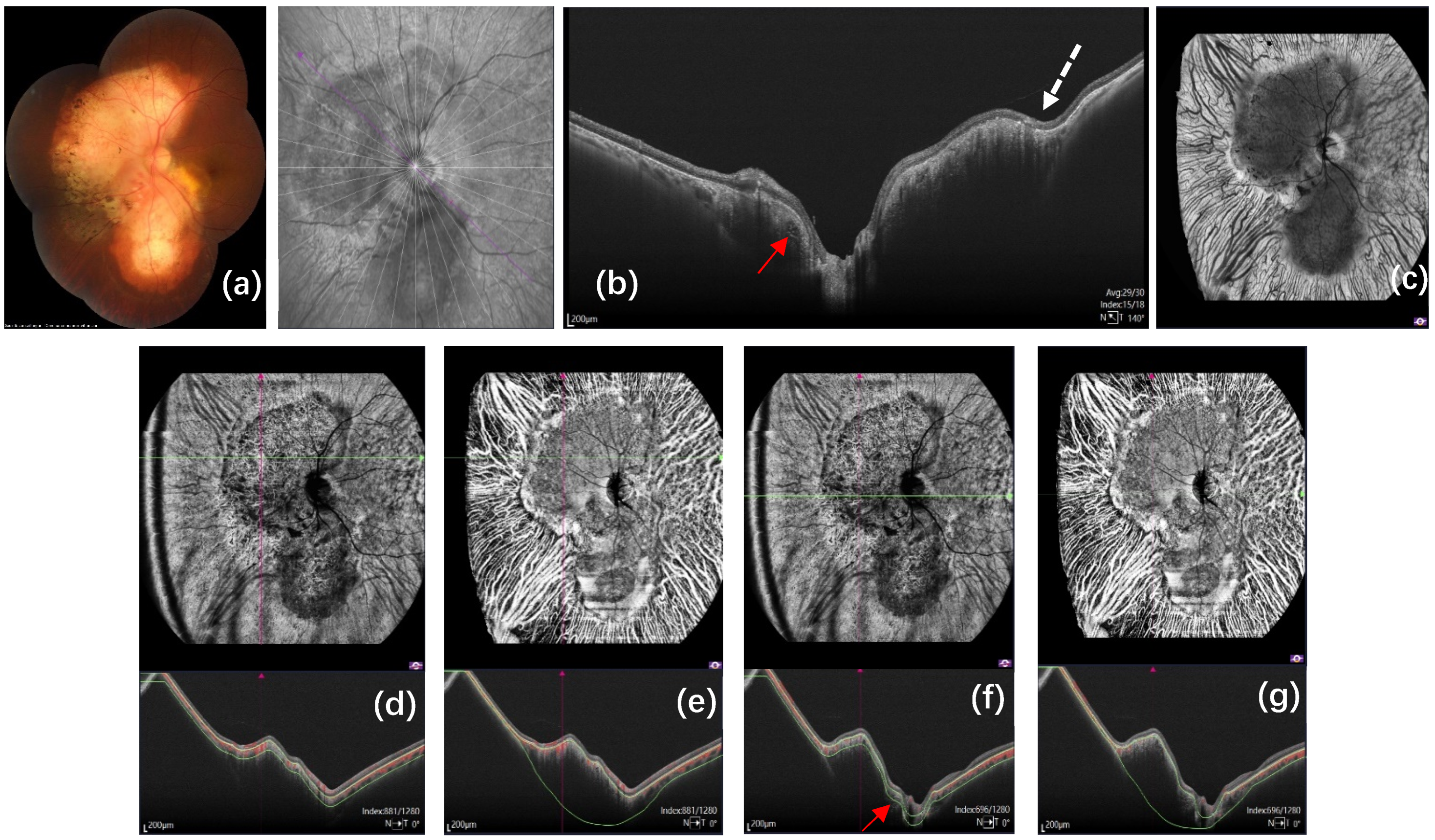
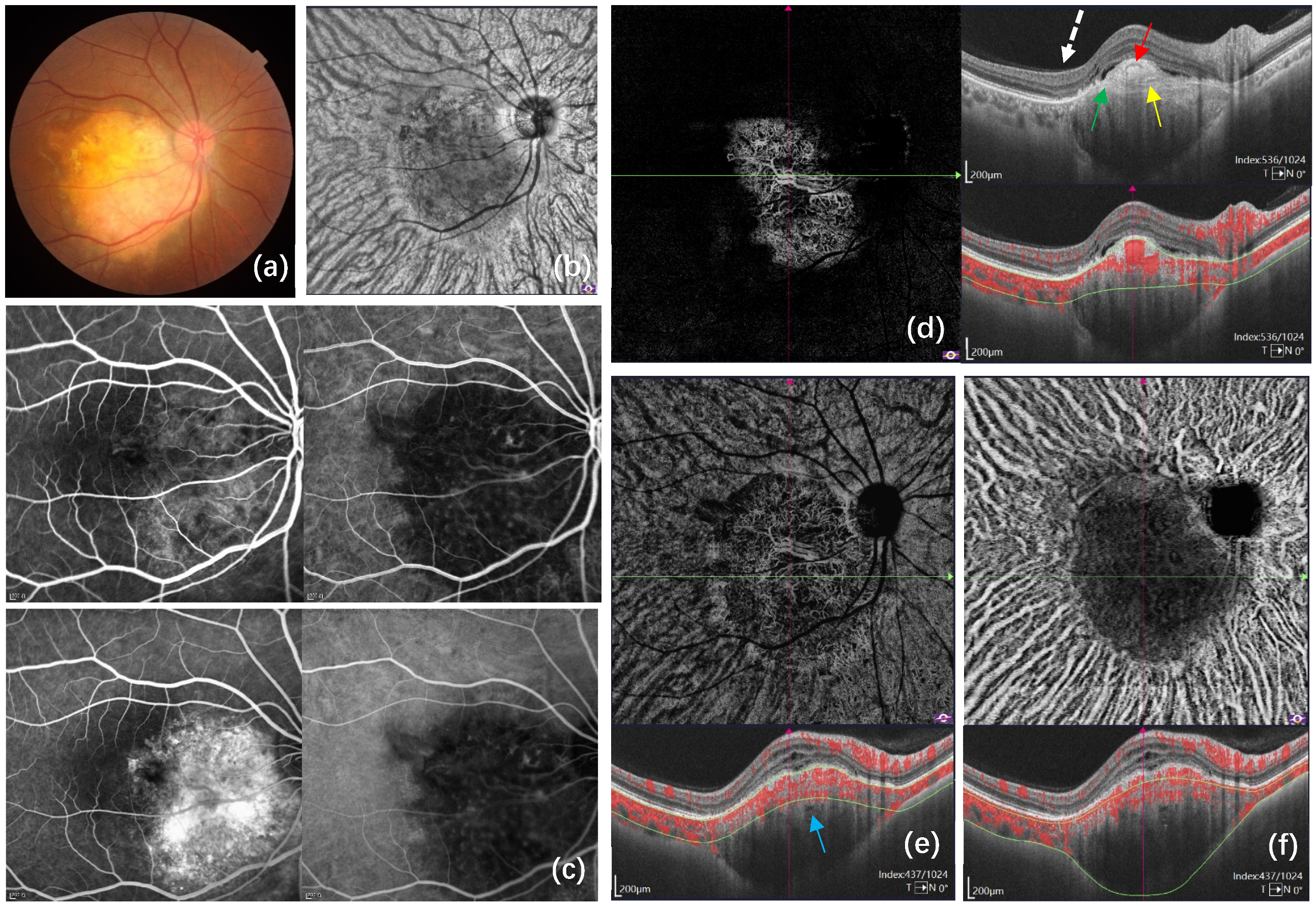
This cross-sectional study enrolled patients diagnosed with CO who were referred to the Eye and ENT Hospital of Fudan University, China, from September 2021 to January 2022. The study was approved by the Institutional Review Board of the Eye and ENT Hospital of Fudan University (protocol code: 2021014, date of approval: 4 February 2021). All procedures were conducted in accordance with the principles of the Declaration of Helsinki. Subjects with poor visual acuity due to severe media opacity and inability to fixate for OCTA image acquirement were excluded from the study.
For each patient, a detailed medical record was compiled, and a complete ophthalmologic examination performed at the baseline visit. Demographic data included age, gender, laterality, best-corrected visual acuity (BCVA), and history of intravitreal anti-vascular endothelial growth factor (anti-VEGF) injections. Multimodal imaging included color fundus photography (Topcon TRC50LX; Topcon, Tokyo, Japan), B-scan ultrasonography or computerized tomography, and simultaneous FA and ICGA by Spectralis HRA + OCT (Heidelberg Engineering, Heidelberg, Germany). Tumor characteristics included location (macula, juxtapapillary, or circumpapillary), greatest linear dimension on ultrasonography, presence of CNV and focal choroidal excavation (FCE), whether hyperreflective tumor-like tissue was growing over Bruch’s membrane, and number of tumors (single or multi-focal).
All patients underwent SS-OCT and SS-OCTA (TowardPi BMizar, TowardPi Medical Technology, Beijing, China) after pupil dilation to obtain amplitude-decorrelation angiography images. For SS-OCT, we captured radiation and raster scans of each osteoma lesion. A vertical-cavity surface-emitting laser was used to sweep sources with an A-scan rate of 400 KHz (BMizar) and wavelength centered at 1060 nm. The bandwidth of 100 nm enabled an axial optical resolution of 3.8 μm; the transverse resolution was 10 μm. The high coherence range provided homogeneous signal strength over a depth range of 6 mm for the vitreous, retina, choroid, and sclera. The eye tracking rate of 128 Hz eliminated interference from eye motion and blinks. The special lens of TowardPi OCT system does not like additional-lens-using for imaging the anterior segment; it is an optical design within a complete set of the system. With a group of large-diameter lenses (ocular lenses more than 60 mm across), the field of view (FOV) of the system reaches up to 120°, while maintaining a lateral resolution of 10 um. The B-scan length can be adjusted from 3 to 24 mm, according to the tumor size. A 24 mm B-scan consists of 1536 A-scans, with 2560 samples along each A-scan. Each scan position can be repeated up to 256 times to obtain an average image with high SNR. For SS-OCTA, the choice of 24 × 20 mm, 18 × 18 mm, or 12 × 12 mm scanning protocols enables a large view of the osteoma lesion according to the tumor size, enabling high-resolution images of CNV and feeder vessels. Unlike 2D images from color photographs or FA, OCTA images consist of three-dimensional data points. The collection of width, height, and depth data leads to a marked increase in data volume. A single 24 × 20 mm OCTA image consists of 1280 line positions, 1536 A-scans of each line, and 2560 points on each A-scan, with the scanning repeated at least twice. The interval of A- and B-scans is 15.625 μm, similar to most HD OCTA images at small sizes. As a result, a TowardPi OCTA image with a width of 24 mm comprises over ten billion voxels. In addition, a 400 KHz swept source is insufficient to bring a 120° OCTA imaging modality into real practice. Amongst the supporting hardware, the DAQ is one of the key components. The DAQ needs to have rapid operation to overmatch the 400 KHz rate, with a high S/N ratio, which is extremely costly in the industrial market and is therefore not ideal for a commercial ophthalmic imaging device. The inexpensive TowardPi DAQ card operates at 6 GB/s, 12 bits, and a SNR of 56 dB, which is suitable for the 400 KHz laser source. Theoretically, the acquisition time for a single 120° OCTA image is approximately 11 s. Given the reality of eye motion and blinks, the average acquisition time in daily practice is approximately 15 s. As for the choroid vessels, traditional OCTA is sensitive to retinal blood flow as well as the choriocapillaris, but the imaging of flow from the choroidal Satter’s layer and Haller’s layer, which are deeper and thicker than in the retina, is a challenge for OCTA. The lower signal strength and saturation weaken the capability of visualization with the spectral domain of swept-source OCT. TowardPi has developed a three-dimensional spatial identification algorithm to visualize choroidal vessels from Sattler’s layer and Haller’s layer. The morphological reconstruction of large choroidal vessels was achieved by using Threshold Segmentation Algorithm to identify the OCT signal differences between the large vessels and the stroma, supplemented by various signal enhancement and pseudo-signal elimination techniques. As a result, medium- and large-sized choroid vessels are distinctive and vivid, and there is almost no mask from false retinal vessel shadows. In addition, the dataset is in three dimensions, which enables quantification analysis for choroid vessels in various 2D and 3D methods. For the SS-OCTA imaging of this study, automatic segmentation was first used to identify the avascular retina and choroidal vessel layers. The outer avascular retina slab (from the outer plexiform layer to Bruch’s membrane) was considered to identify the shape of neovascularization. The upper boundary of the choroidal vessels slab followed the surface of the tumor, and the lower boundary followed the interface between the tumor and the sclera. Manual adjustment on the segmentation was then conducted in all cases with segmentation errors to optimally visualize the morphology of vasculature within the CO, as well as the boundary of the tumor. All OCTA images were carefully reviewed and analyzed by two of the authors (YX and MW).

3. Results

The patients’ characteristics and tumor features are listed in Table 1. Twenty-three eyes of 21 patients were enrolled in the study, including 17 females and four males. The mean age at diagnosis was 32.6 ± 8.6 years (range 16–50 years). The right eye was involved in eight patients, and the left eye in 11 patients. Two patients were affected on both eyes. The mean baseline BCVA was 0.55 ± 0.46 (range 0.0–1.4), and the mean greatest linear dimension of tumor was 7.03 ± 3.87mm (range 1.96–16.36). There were 20 eyes that had single tumors and three eyes that had multi-focal tumors, amongst which macular involvement was seen in 10 tumors, juxtapapillary superior in four tumors, juxtapapillary inferior in one tumor, juxtapapillary temporal in two tumors, juxtapapillary nasal in one tumor, and circumpapillary with macular involvement in seven tumors. Prior to enrollment in the study, 12 eyes had been treated with intravitreal injections of anti-VEGF treatment for the presence of CNV.
On SS-OCT, all eyes showed unique features, as previously reported [13,18], including horizontal lamellar lines, hyperreflective horizontal lines, horizontal tubular lamellae with an optically empty center, vertical tubular lamella, and regions of speckled reflective dots within the CO. In 17 eyes, the hyperreflective area was located above the disrupted Bruch’s membrane (73.9%), and several intratumor vessels were seen in the hyperreflective area. The sclero-choroidal junction was detectable in all tumors, and a posterior ciliary vessel penetrating the sclera was also seen. Vessels between the tumor and the sclero-choroidal junction were observed as structures with low or medium internal reflectivity in seven eyes (presumed thinning of Haller’s layer that was pushed toward the outside and compressed). “Choroidal loculation of fluid” was found in four eyes and FCE in 13 eyes, of which nine had a CNV lesion on the slope of, or adjacent to, the FCE (Figure 1).
On SS-OCTA and en face imaging, the tumor boundary could be clearly demarcated from adjacent vessels of the choroidal Sattler’s layer and Haller’s layer in all eyes. By adjusting the segmentation lines on the point-to-point aligned B-scan images, we were able to identify the anterior and posterior surfaces of the tumor. The maximum area of a single captured OCTA image was 24 × 20 mm, which enabled observation of the details of the tumor in a single image without the need to make a montage. The blood flow of the CO was detected mostly within the choriocapillaries and partly within the Sattler’s layer on B-scan. On corresponding en face images the intrinsic feeder vessels of the CO displayed various patterns including ginseng, instant noodle, growth ring, tangle, spider web, medusa, seafan, and irregular shape. In the avascular retinal layer, CNV was identified in 13 eyes as numerous branching or radiating vessels connecting with feeder vessels. On the composite B-scan the neovascular network corresponded to a hyperreflective area above the disrupted Bruch’s membrane. Hyporeflective tubular lamellae (presumed to be feeder vessels of the tumor) showing signs of blood flow signal and hyperreflective horizontal lamella (presumed to be bone lamella or cement lines) were observed within the hyperreflective area. The CNV network of this phenotype was found either at the borderline between the calcified and decalcified regions, or along the margin of the tumor. The hyporeflective tubular areas on SS-OCT within the CO under Bruch’s membrane, which were interpreted as intratumoral vessels or bone vascular channels in a previous study [13], did not show any signs of blood flow signal on SS-OCTA (Figure 2, Figure 3, Figure 4 and Figure 5).

4. Discussion

In the present study, the tumor boundary was clearly observed on en face images of SS-OCTA and was demarcated from adjacent normal choroidal vasculature including choriocapillaris (CC) and medium- and large-sized choroidal vessels. Compared with previous studies that monitored CO vasculature in the CC layer using relatively limited OCTA techniques [5,9,10,19,20,21,22], our result provides greater insight into the CO vasculature. Despite the advantages of OCTA over FA and ICGA, in terms of visualizing more detailed microvascular flow information at various levels in the retina and choroid, the imaging of blood flow from the choroidal Sattler’s layer and Haller’s layer is a challenge for OCTA because of scattering by the pigment of the RPE and by vessels in the CC, which results in lower signal strength and saturation, thereby impairing visualization [23]. TowardPi SS-OCTA offers improved visualization of medium- and large-sized choroidal vessels. Using this approach, the CO vasculature is distinct from normal choroidal structures, and the blood flow of the CO was found to be located mainly within the choriocapillaris and partly the Sattler’s layer, which is consistent with an earlier histopathological study of CO that showed the tumor was located between the CC and the outer choroidal tissue [1]. Moreover, there were some decalcification areas of the osteoma, where overlying RPE hyperplasia or atrophied and discontinuous or compressed choroidal vessels, displaying no blood flow on the corresponding SS-OCTA B-scan; this was also consistent with previous histopathological findings that the choriocapillaris was narrowed and obliterated in most areas of focally depigmented RPE or clumps of pigment granules observed along Bruch’s membrane and attached to the outer retinal layers [1,24].
The major factor causing visual compromise from CO is the development of CNV, which is often associated with subretinal fluid and hemorrhage [25]. Detecting CNV in eyes with osteoma using traditional imaging (e.g., FA and ICGA) can be challenging because of high tissue density within the tumor, and secondary RPE abnormalities that promote irregular and persistent hyperfluorescence; consequently, it is difficult to distinguish CNV from feeder vessels [21,26]. OCTA is superior to FA and ICGA in terms of visualizing CNV, including the contour and shape of vessels [27]. Since first reported by Szelog in 2016 [5], several studies have described CNV in patients with CO, as detected by OCTA from a relatively small number of cases [8,9,10,22,28,29]. Most studies were case reports that described the OCTA features of CO as tiny, isolated flow-network lesions between the outer retina and choriocapillaris, similar to type 1 or type 2 CNV [8,22,30]. However, Azad et al. [16] hypothesized a vascular connection between CNV and the intrinsic feeder vessels of the CO. Sagar et al. [10] differentiated the vascular network of CNV from the intrinsic vasculature of the CO, and showed on OCTA the feeder vessels extending into the tumor from the surrounding choroid. A recent study using SS-OCTA demonstrated that a sea-fan vascular network and type 2 neovascularization co-existed in the same eye, and that the tumor vasculature may have derived from one or both of these neovascular lesions [20]. Similarly, our study showed an interlacing pattern of CNV secondary to CO, presenting as numerous branching or radiating vessels connecting with feeder vessels in an en face image. In addition, cross-sectional B-scan images showed the corresponding hyperreflective lesion to contain hyporeflective tubular lamella that could detect blood flow signal, probably representing feeder vessels of the tumor, and hyperreflective lamellar lines representing unique features of the osteoma such as bone lamella or cement lines. To our knowledge, this detailed observation of the neovascular network in CO is revealed for the first time by SS-OCTA, indicating a distinct anatomical connection between CNV and the intrinsic vascularization of the tumor, which is quite different from CNV secondary to other common retinal and choroidal diseases. The composition of the newly developed vasculature network may include feeder vessels of the tumor, both growing intersected and stimulating interaction with one other, suggesting unique pathological features of CO.
Another important finding of this study is that the hyperreflective lesion could be detected above Bruch’s membrane in the decalcified region of osteoma lesions, accompanied by rupture of the overlying Bruch’s membrane in 73.9% of our patients. This result is inconsistent with previous SD-OCT and post-enucleation results that indicated all the tumor-related vasculature is located in the inner tumor, not outside the area between Bruch’s membrane and the RPE layer. Navajas et al. [31] were the first to report hyperreflective material above Bruch’s membrane, but since no disruption of the membrane was observed on SD-OCT, they speculated the material was extensive fibrous RPE metaplasia, as it was considered unlikely that the tumor tissue could grow over the intact Bruch’s membrane. Hayashi et al. [17] suggested that the hyperreflective area above Bruch’s membrane may be tumor-like tissue, as they observed a clear disruption of Bruch’s membrane in a case of osteoma by SS-OCT. Our previous study of 73 eyes with CO found that these hyperreflective tumor-like lesions presented as bone trabecular and bone appearance on SS-OCT in 18 eyes (24.7%), further supporting the hypothesis that osteoma tissue could break through Bruch’s membrane and grow along its surface [32]. The incidence of the hyperreflective area being located above the disrupted Bruch’s member in the present study was up to 73.9%, probably due to the higher resolution of this SS-OCT platform and the combined analyses of SS-OCTA. Of the 17 eyes showing this finding, the hyperreflective tumor-like tissues in four eyes showed blood flow on OCTA without subretinal hemorrhage or fluid and fluorescent leakage on FA. This does not indicate CNV but may be a precursor of active neovasculature, in view of the aforementioned relationship between the tumor’s intrinsic feeder vessels and CNV. Thus, these hyperreflective lesions require close observation for early detection and timely treatment of severe complications.
Similar to previous SD-OCT studies, our SS-OCT study showed unique features including horizontal lamellar lines, hyperreflective horizontal lines, horizontal tubular lamella with an optically empty center, vertical tubular lamella, and regions of speckled reflective dots within the CO. However, as reported by Chehab et al. [19], and Zhou N et al. [20], the hyporeflective tubular lamellae that were presumed to be Haversian canals, Volkmann canals, or vascular channels as described by Shields et al. [13], did not show any flow signal in SS-OCTA. The blood flow inside these channel areas may be of quiescent neovascularization, meaning the slow velocity of the blood flow cannot be captured by OCTA. Moreover, the presence of “choroidal loculation of fluid”, which has been observed in central serous chorioretinopathy and only described in a case of CO [33], was found in our patients. This OCT finding, which should be distinguished from the compressed thinning of Haller’s layer, appears as hyporeflective spaces in the outer choroid with an angular inner border, and larger in size than the largest choroidal vessels. It has been suggested that “choroidal loculation of fluid” might drive fluid into the sub-RPE and subretinal spaces [34], and it is therefore hypothesized to play a role in the presence of subretinal fluid in CO patients without CNV.
In the present study, nine eyes developed FCE in correspondence with or proximity to a CNV lesion. This is not surprising, as CNV has been reported to occur on the slope or bottom of eyes with FCE [35,36]. In addition, Gan et al. [37], showed that CO is the most common disease in eyes with FCEs and that all FCEs in CO were located at the edge of the osteoma. Since FCE was first reported by Jampol et al. [38], in 2006, it has been elucidated in several retinal and choroidal diseases. Margolis et al. [39], classified FCE into conforming lesions, in which the overlying retina is close to the RPE, and nonconforming lesions, in which a hyporeflective space is visible between the retina and the RPE. Introini et al. [40], were the first to describe the progression from conforming to nonconforming FCE in a case of bilateral osteoma, including one case in which CNV had not occurred in the eye with FCE. The other two reports of FCE in choroidal osteoma described a gradual flattening of an initially irregular RPE elevation followed by a depression of the tumor and the eventual formation of a central excavation and a CNV on the slope of, or adjacent to, the FCE [30,41]. In our cases, the FCEs appeared with CNV at the time of enrollment, so the order of FCEs and CNV development is unclear. Further follow-up investigations are needed.

5. Conclusions

We used the newly developed SS-OCT and SS-OCTA platform to capture the detailed features of CO in a single widefield, deep, and fast image. The tumor boundary could be clearly demarcated from adjacent vessels of the choroidal Sattler’s layer and Haller’s layer. The blood flow of the CO was mainly detected within the choriocapillaries and partly within the Sattler’s layer on B-scan. Moreover, the osteoma tissue was found to break through Bruch’s membrane and grow along its surface. Consequently, SS-OCT and SS-OCTA are useful in both the diagnosis and evaluation of CO.

Author Contributions

Conceptualization, Y.X. and M.W.; methodology, Y.X., Q.C., Y.Z., X.Y. and M.W.; software, Y.X. and J.Z.; validation, Y.X. and M.W.; formal analysis, Y.X. and M.W.; investigation, Y.X., Q.C., Y.Z. and M.W.; resources, Y.X., Q.C., Y.Z., X.Y., W.L., L.L., K.W. and M.W.; data curation, Y.X.; writing—original draft preparation, Y.X.; writing—review and editing, M.W.; visualization, Y.X.; supervision, M.W.; project administration, M.W.; funding acquisition, Q.C. and M.W. All authors have read and agreed to the published version of the manuscript.

Funding

This research was funded by the Excellent Doctor-Excellent Clinical Researcher Project of Eye and ENT Hospital, Fudan University (Grant No. SYA202009) and the National Natural Science Foundation of China (Grant No. 82171078).

Institutional Review Board Statement

The study was conducted according to the guidelines of the Declaration of Helsinki and approved by the Institutional Review Board of the Eye and ENT Hospital of Fudan University, protocol code: 2021014, date of approval: 4 February 2021.

Informed Consent Statement

Informed consent was obtained from all subjects involved in the study.

Data Availability Statement

The data presented in this study are available on request from the corresponding author. The data are not publicly available due to privacy protection laws.

Conflicts of Interest

The authors declare no conflict of interest.

References

  1. Gass, J.D.; Guerry, R.K.; Jack, R.L.; Harris, G. Choroidal osteoma. Arch. Ophthalmol. 1978, 96, 428–435. [Google Scholar] [CrossRef] [PubMed]
  2. Shields, C.L.; Sun, H.; Demirci, H.; Shields, J.A. Factors predictive of tumor growth, tumor decalcification, choroidal neovascularization, and visual outcome in 74 eyes with choroidal osteoma. Arch. Ophthalmol. 2005, 123, 1658–1666. [Google Scholar] [CrossRef] [Green Version]
  3. Chen, J.; Lee, L.; Gass, J.D. Choroidal osteoma: Evidence of progression and decalcification over 20 years. Clin. Exp. Optom. 2006, 89, 90–94. [Google Scholar] [CrossRef] [PubMed]
  4. Shields, C.L.; Shields, J.A.; Augsburger, J.J. Choroidal osteoma. Surv. Ophthalmol. 1988, 33, 17–27. [Google Scholar] [CrossRef]
  5. Szelog, J.T.; Bonini Filho, M.A.; Lally, D.R.; de Carlo, T.E.; Duker, J.S. Optical coherence tomography angiography for detecting choroidal neovascularization secondary to choroidal osteoma. Ophthalmic Surg. Lasers Imaging Retin. 2016, 47, 69–72. [Google Scholar] [CrossRef] [PubMed]
  6. Shields, C.L.; Perez, B.; Materin, M.A.; Mehta, S.; Shields, J.A. Optical coherence tomography of choroidal osteoma in 22 cases: Evidence for photoreceptor atrophy over the decalcified portion of the tumor. Ophthalmology 2007, 114, e53–e58. [Google Scholar] [CrossRef] [PubMed]
  7. Freton, A.; Finger, P.T. Spectral domain-optical coherence tomography analysis of choroidal osteoma. Br. J. Ophthalmol. 2012, 96, 224–228. [Google Scholar] [CrossRef] [PubMed]
  8. Cennamo, G.; Romano, M.R.; Iovino, C.; Velotti, N.; Breve, M.A.; de Crecchio, G.; Cennamo, G. OCT angiography in choroidal neovascularization secondary to choroidal osteoma. Acta Ophthalmol. 2017, 95, e152–e154. [Google Scholar] [CrossRef] [Green Version]
  9. Grisolia, A.B.D.; de França Martins, M.; Demirci, H. Imaging of neovascular membrane over a choroidal osteoma by OCT angiography. Ophthalmology 2018, 125, 236. [Google Scholar] [CrossRef]
  10. Sagar, P.; Shanmugam, M.; Ramanjulu, R.; Konana, V.K. OCT angiography characteristics of choroidal osteoma. Ophthalmol. Retina 2018, 2, 77–79. [Google Scholar] [CrossRef]
  11. Pellegrini, M.; Invernizzi, A.; Giani, A.; Staurenghi, G. Enhanced depth imaging optical coherence tomography features of choroidal osteoma. Retina 2014, 34, 958–963. [Google Scholar] [CrossRef]
  12. Erol, M.K.; Coban, D.T.; Ceran, B.B.; Bulut, M. Enhanced depth imaging optical coherence tomography and fundus autofluorescence findings in bilateral choroidal osteoma: A case report. Arq. Bras. Oftalmol. 2013, 76, 189–191. [Google Scholar] [CrossRef] [Green Version]
  13. Shields, C.L.; Arepalli, S.; Atalay, H.T.; Ferenczy, S.R.; Fulco, E.; Shields, J.A. Choroidal osteoma shows bone lamella and vascular channels on enhanced depth imaging optical coherence tomography in 15 eyes. Retina 2015, 35, 750–757. [Google Scholar] [CrossRef]
  14. Dinah, C.; Sandinha, T. Enhanced depth imaging as an adjunctive tool in the diagnosis of decalcified choroidal osteoma. Eye 2014, 28, 356–358. [Google Scholar] [CrossRef] [Green Version]
  15. Laíns, I.; Wang, J.C.; Cui, Y.; Katz, R.; Vingopoulos, F.; Staurenghi, G.; Vavvasa, D.G.; Millera, J.W.; Millerab, J.B. Retinal applications of swept source optical coherence tomography (OCT) and optical coherence tomography angiography (OCTA). Prog. Retin. Eye Res. 2021, 84, 100951. [Google Scholar] [CrossRef]
  16. Azad, S.V.; Takkar, B.; Venkatesh, P.; Kumar, A. Swept source: Optical coherence tomography angiography features of choroidal osteoma with choroidal neovascular membrane. BMJ Case Rep. 2016, bcr2016215899. [Google Scholar] [CrossRef] [Green Version]
  17. Hayashi, Y.; Mitamura, Y.; Egawa, M.; Semba, K.; Nagasawa, T. Swept-source optical coherence tomographic findings of choroidal osteoma. Case Rep. Ophthalmol. 2014, 5, 195–202. [Google Scholar] [CrossRef]
  18. Azad, S.V.; Kumar, V.; Chawla, R.; Kashyap, B.; Temkar, S.; Kumar, A.; Venkatesh, P.; Vohra, R.; Molla, K.; Sharma, A. In vivo optical biopsy of choroidal osteoma: A swept source optical coherence tomography-based tumor characterization. Ther. Adv. Ophthalmol. 2020, 12, 2515841420922740. [Google Scholar] [CrossRef]
  19. Chehab, H.E.; Dot, C.; Mathis, T.; Agard, E.; Kodjikian, L. Contribution of swept-source OCT-angiography in analysis of choroidal osteoma and its quiescent neovascular complications: A case study. Am. J. Ophthalmol. Case Rep. 2020, 19, 100769. [Google Scholar] [CrossRef]
  20. Zhou, N.; Xu, X.; Liu, Y.; Wei, W.; Peng, X. Appearance of tumor vessels in patients with choroidal osteoma using swept-source optical coherence tomographic angiography. Front. Oncol. 2021, 11, 762394. [Google Scholar] [CrossRef]
  21. Olguin-Manríquez, F.; Enríquez, A.B.; Crim, N.; Meraz-Gutierrez, M.; Soberón-Ventura, V.; Ávila, I.; Morales-Canton, V.; Jimenez-Sierra, J.M. Multimodal imaging in choroidal osteoma. Int. J. Retin. Vitreous 2018, 4, 30. [Google Scholar] [CrossRef] [PubMed]
  22. Shen, C.; Yan, S.; Du, M.; Zhao, H.; Shao, L.; Hu, Y. Assessment of choroidal osteoma complicating choroidal neovascularization by optical coherence tomography angiography. Int. Ophthalmol. 2018, 38, 787–792. [Google Scholar] [CrossRef] [PubMed] [Green Version]
  23. Wang, F.; Zhang, Q.; Deegan, A.J.; Chang, J.; Wang, R.K. Comparing imaging capabilities of spectral domain and swept source optical coherence tomography angiography in healthy subjects and central serous retinopathy. Eye Vis. 2018, 5, 19. [Google Scholar] [CrossRef] [PubMed]
  24. Williams, A.T.; Font, R.L.; Van Dyk, H.J.; Riekhof, F.T. Osseous choristoma of the choroid simulating a choroidal melanoma. Association with a positive 32P test. Arch. Ophthalmol. 1978, 96, 1874–1877. [Google Scholar] [CrossRef]
  25. Aylward, G.W.; Chang, T.S.; Pautler, S.E.; Gass, J.D. A long-term follow-up of choroidal osteoma. Arch. Ophthalmol. 1998, 116, 1337–1341. [Google Scholar] [CrossRef] [Green Version]
  26. Lafaut, B.A.; Mestdagh, C.; Kohno, T.; Gaudric, A.; De Laey, J.J. Indocyanine green angiography in choroidal osteoma. Graefes Arch. Clin. Exp. Ophthalmol. 1997, 235, 330–337. [Google Scholar] [CrossRef]
  27. Toledo, J.J.; Asencio, M.; García, J.R.; Morales, L.A.; Tomkinson, C.; Cajigal, C. OCT Angiography: Imaging of choroidal and retinal tumors. Ophthalmol. Retin. 2018, 2, 613–622. [Google Scholar] [CrossRef]
  28. Basavaraj, T.M.; Galiyugavaradhan, S. Sequential imaging of a case of choroidal osteoma using swept-source OCT and optical coherence tomography angiography: A 4-year follow-up study. Indian J. Ophthalmol. 2019, 67, 2097–2100. [Google Scholar]
  29. Furino, C.; Di Antonio, L.; Grassi, M.O.; Rispoli, M.; Reibaldi, M.; Niro, A.; Alessio, G. Choroidal neovascularization due to choroidal osteoma treated with anti-vascular endothelial growth factor therapy: An optical coherence tomography angiography study. Eur. J. Ophthalmol. 2019, 29, 323–329. [Google Scholar] [CrossRef]
  30. Pierro, L.; Marchese, A.; Gagliardi, M.; Introini, U.; Battaglia Parodi, M.; Casalino, G.; Bandello, F. Choroidal excavation in choroidal osteoma complicated by choroidal neovascularization. Eye 2017, 31, 1740–1743. [Google Scholar] [CrossRef] [Green Version]
  31. Navajas, E.V.; Costa, R.A.; Calucci, D.; Hammoudi, D.S.; Simpson, E.R.; Altomare, F. Multimodal fundus imaging in choroidal osteoma. Am. J. Ophthalmol. 2012, 153, 890–895. [Google Scholar] [CrossRef]
  32. Yi, X.; Min, W.; Qing, C.; Yongjin, Z. Swept-source optical coherence tomography analysis of choroidal osteoma. Chin. J. Ocul. Fundus Dis. 2020, 36, 435–441. [Google Scholar]
  33. Leitão Guerra, R.L.; Arantes, R.C.; Marback, E.F.; Shields, C.L. Novel OCT findings in choroidal osteoma: Brief report. Int. J. Retin. Vitreous 2021, 7, 46. [Google Scholar] [CrossRef]
  34. Spaide, R.F.; Ryan, E.H., Jr. Loculation of fluid in the posterior choroid in eyes with central serous chorioretinopathy. Am. J. Ophthalmol. 2015, 160, 1211–1216. [Google Scholar] [CrossRef]
  35. Xu, H.; Zeng, F.; Shi, D.; Sun, X.; Chen, X.; Bai, Y. Focal choroidal excavation complicated by choroidal neovascularization. Ophthalmology 2014, 121, 246–250. [Google Scholar] [CrossRef]
  36. Lee, J.H.; Lee, W.K. Choroidal neovascularization associated with focal choroidal excavation. Am. J. Ophthalmol. 2014, 157, 710–718. [Google Scholar] [CrossRef]
  37. Gan, Y.; Ji, Y.; Zuo, C.; Su, Y.; Liao, N.; Zhang, X.; Zeng, Y.; Wen, F. Correlation between focal choroidal excavation and underying retinochoridal disease: A pathological hypothesis from clinical obervation. Retina 2022, 42, 348–356. [Google Scholar] [CrossRef]
  38. Jampol, L.M.; Shankle, J.; Schroeder, R.; Tornambe, P.; Spaide, R.F.; Hee, M.R. Diagnostic and therapeutic challenges. Retina 2006, 26, 1072–1076. [Google Scholar] [CrossRef]
  39. Margolis, R.; Mukkamala, S.K.; Jampol, L.M.; Spaide, R.F.; Ober, M.D.; Sorenson, J.A.; Gentile, R.C.; Miller, J.A.; Sherman, J.; Freund, K.B. The expanded spectrum of focal choroidal excavation. Arch. Ophthalmol. 2011, 129, 1320–1325. [Google Scholar] [CrossRef] [Green Version]
  40. Introini, U.; Casalino, G.; Parodi, M.B.; Bandello, F.; London, N.J. Diagnostic and therapeutic challenges. Retina 2016, 36, 422–427. [Google Scholar] [CrossRef]
  41. Kamalden, T.A.; Lingam, G.; Sundar, G. Bone remodeling in choroidal osteoma monitored by fundus photography and spectral-domain optical coherence tomography. Ocul. Oncol. Pathol. 2014, 1, 13–18. [Google Scholar] [CrossRef] [PubMed] [Green Version]
Figure 1. Color fundus photography (a,c,e,g) and SS-OCT images (b,d,f,h) of patients 14, 19, 2, and 16 (see Table 1), respectively. SS-OCT imaging shows unique features of the CO, including horizontal lamellar lines (red arrows), hyperreflective horizontal lines (yellow arrows), horizontal tubular lamellae with an optically empty center, vertical tubular lamellae (orange arrows), and regions of speckled reflective dots (S). The hyperreflective area is located above the disrupted Bruch’s membrane and contains several intratumor vessels. The sclero-choroidal junction is clearly seen, and vessels between the tumor and the sclero-choroidal junction appear as structures with low or medium internal reflectivity (blue arrowheads, presumed thinning of Haller’s layer that was pushed toward the outside and compressed). The tumor-like hyperreflective tissue is located above the disrupted Bruch’s membrane (green arrows). “Choroidal loculation of fluid” (green asterisks) was also observed.
Applsci 12 04472 g001
Figure 2. Multimodal imaging of patient 5 (see Table 1): (a) fundus photography shows a well-de fined circumpapillary osteoma with macular involvement; (b) SS-OCT shows a region of speckled reflective dots, with obvious focal choroidal excavation (dashed arrow); (c) an en face image corresponding to (g) shows the clear border of the entire osteoma; (d,f) an SS-OCTA image of the choriocapillaris layer shows the blood flow signal of osteoma to be located mainly within the choriocapillaris and partly Sattler’s layer on a composite B-scan. Areas of overlying RPE hyperplasia and discontinuous or compressed choroidal vessels show no blood flow signal (yellow arrow). The hyporeflective tubular areas (red arrow) that were interpreted as intratumoral vessels did not show any blood flow signal; (e,g) SS-OCTA segmentation covering the entire border of the CO on aligned B-scan images shows the boundary of the tumor clearly demarcated from adjacent vessels of the choroidal Sattler’s layer and Haller’s layer.
Applsci 12 04472 g002
Figure 3. Multimodal imaging of patient 4 (see Table 1): (a) fundus photography shows a well-defined circumpapillary osteoma with macular involvement; (b) SS-OCT shows the unique CO features of horizontal lamellar lines, hyperreflective horizontal lines, horizontal tubular lamella, and vertical tubular lamella (red arrow) with obvious focal choroidal excavation (dashed white arrow); (c) an en face image corresponding to (g) shows the clear border of the entire osteoma; (d,f) an SS-OCTA image of the choriocapillaris layer shows the blood flow signal of the CO to be located mainly within the choriocapillaris and partly the Sattler’s layer on a composite B-scan. The hyporeflective tubular areas (red arrow), which were interpreted as intratumoral vessels, did not show a blood flow signal; (e,g) SS-OCTA segmentation covering the entire border of the osteoma on aligned B-scan images shows the tumor boundary clearly demarcated from adjacent vessels of the choroidal Sattler’s layer and Haller’s layer.
Applsci 12 04472 g003
Figure 4. Multimodal imaging of patient 1 (see Table 1): (a) fundus photography shows an orange-yellow CO at the macula with subretinal hemorrhage; (b) an en face image corresponding to (f); (c) FA and ICGA show an early hyperfluorescent network with dye leakage; (d) the avascular layer of SS-OCTA and corresponding B-scan show a hyperreflective area (the neovascular network interlacing with feeder vessels of the tumor) growing above the disrupted Bruch’s member (green arrow) on the slope of the focal choroidal excavation (dashed white arrow). This area contains hyporeflective tubular lamella (red arrow, presumed to be feeder vessels of the tumor) that could show blood flow signals and hyperreflective horizontal lamellar lines (yellow arrow, presumed to be bone lamella or cement lines); (e) SS-OCTA of the choriocapillaris layer shows the blood flow signal of the osteoma is located mainly within the choriocapillaris and partly the Sattler’s layer on the composite B-scan. The hyporeflective tubular areas (blue arrow), which were interpreted as intratumoral vessels, did not detect a flow signal; (f) SS-OCTA segmentation covering the entire border of the osteoma on the aligned B-scan images shows the boundary of the tumor clearly demarcated from the adjacent vessels of the choroidal Sattler’s layer and Haller’s layer.
Applsci 12 04472 g004
Figure 5. Multimodal imaging of patient 18 (see Table 1): (a) fundus photography shows a circumpapillary CO with macular involvement; (b) an en face image corresponding to (e); (c) the avascular layer and corresponding B-scan of SS-OCTA show hyperreflective tumor-like tissue (red arrow) above the disrupted Bruch’s membrane (green arrow) that shows blood flow without subretinal hemorrhage or fluid, which is not indicative of CNV but may be a precursor to active neovasculature; (d) the choriocapillaris layer of SS-OCTA shows the blood flow signal of the osteoma is located mainly within the choriocapillaris and partly the Sattler’s layer on the composite B-scan; (e) SS-OCTA segmentation covering the entire border of the osteoma on the aligned B-scan images shows the boundary of the tumor clearly demarcated from the adjacent vessels of the choroidal Sattler’s layer and Haller’s layer.
Applsci 12 04472 g005
Table 1. Demographic and clinical features of patients with choroidal osteoma in the study.
Patient NumberAge, YearsGenderAffected EyeBaseline BCVA
(logMAR)
Number of TumorsTumor Greatest Linear
Dimension, mm
Tumor LocationPrevious TreatmentCNVGrow over Bruch
Membrane
FCE
132FOD0.8Single4.63MaculaNoneYYY
242FOS0.3Single5.78Juxtapapillary superiorAnti-VEGF injectionsYYY
332MOS1.3Single10.99Circumpapillary with macular involvementNone YY
429FOS0.2Single16.36Circumpapillary with macular involvementAnti-VEGF injectionsYYY
537FOD1.4Single14.07Circumpapillary with macular involvementAnti-VEGF injectionsYYY
650MOD0.1Single2.83MaculaAnti-VEGF injectionsYY
723FOU0.1/0.0Single5.40/4.11Macula/Juxtapapillary inferiorAnti-VEGF injections ODY ODY OD
838FOS0.4Single5.7MaculaAnti-VEGF injectionsYY
921MOS0.3Multifocal10.71/5.65Circumpapillary None Y
1046FOS1.0 Single8.18MaculaAnti-VEGF injectionsYYY
1142FOS1.0 Single2.61Juxtapapillary temporalNone
1223MOS0.3Single6.14MaculaNone Y
1326FOD1.3Single8.91MaculaAnti-VEGF injectionsYY
1434FOD0.1Single8.31MaculaAnti-VEGF injectionsYYY
1525FOU0.7/0.8Multifocal3.54/2.95/2.23/4.18/1.96Juxtapapillary superior/superior/temporal/superior/nasalNone
1628FOS0.7Single6.7MaculaAnti-VEGF injectionsYYY
1733FOS0.2Single11.29Circumpapillary with macular involvementAnti-VEGF injectionsYYY
1837FOS0.0 Single8.21Circumpapillary with macular involvementNone YY
1934FOD0.7Single8.01MaculaAnti-VEGF injectionsYYY
2016FOD1.0 Single14.1Circumpapillary with macular involvementNone YY
2137FOD0.0 Single6.37Juxtapapillary temproalNone
F: female; M: male; OD: right eye; OS: left eye; OU: bilateral eyes; BCVA: best-corrected visual acuity; VEGF: vascular endothelial growth factor; CNV: choroidal neovascularization; Y: yes; FCE: focal choroidal excavation.
Publisher’s Note: MDPI stays neutral with regard to jurisdictional claims in published maps and institutional affiliations.

