1. Introduction
Primary reconstruction of ablative mandibular defects may not always be possible due to various reasons. Medical morbidities precluding longer and complex surgeries; fracture of previous load bearing titanium plates, unavailability of microsurgical team, and resection following osteoradionecrosis are some of the common scenarios where secondary mandibular reconstruction is undertaken [
1]. The use of vascularised bone in secondary mandibular reconstruction allows for superior restoration of articulation, deglutition, and mastication; improvement of facial appearance; and patient’s overall quality of life [
2].
The use of computer assisted design (CAD) or computer aided manufacturing (CAM) is well established in primary reconstruction of craniofacial defects involving both maxilla and mandible. Their usage has been applied to post traumatic facial deformity, defect reconstruction after tumor ablation, congenital craniofacial deformity, facial contouring, and orthognathic surgeries (to name a few). Comparison of the outcome of free fibular flap for mandibular reconstruction with and without the application of virtual surgical planning has been carried out and has concluded that the use of VSP is beneficial for optimizing the accuracy, consolidation of bony segments, and operating time, while increase the predictability of results for the surgeon [
3]. However, most of them are limited to defects requiring no or limited changes during surgery [
4,
5,
6,
7,
8,
9].
Patients scheduled for secondary mandibular reconstruction have a unique set of problems. After tumor ablation and irradiation therapy, displacement of the residual bone position by retraction of muscles and ligaments, mixed tissue layers, diminished vessel elasticity is a common finding [
10,
11]. The original mandible as a template for plate bending is not present, the absence of teeth precludes occlusal guidance, and the presence of soft-tissue contracture makes surgical correction more difficult and potentially more hazardous as compared to primary reconstructive surgery performed immediately after bone cancer removal [
12].
Achieving an accurate virtual planning is the first and foremost step of this whole concept of CAD/CAM technology. Having the initial and current radiological data is a prerequisite for virtual planning process in secondary reconstruction so as to obtain a virtual defect template before 3D printing. However, previous imaging data might not be available in every cases. The aim of the study was to devise a virtual planning algorithm where the available clinico-radiologic information along with radiological data bank can be used to design a defect template facilitating the further steps of 3D printing and secondary mandibular reconstruction.
2. Materials and Methods
A database consisting all patients who underwent surgery for secondary mandibular reconstruction between 2014 and 2019, co-operated by senior surgeons (Lin CH and Liao HT), was retrospectively reviewed after obtaining ethical approval from the Institutional Review Board of Chang Gung Memorial Hospital, Taiwan (No.202100984B0). The database search included patients who underwent mandibular microvascular reconstructions in head and neck post-ablation defects.
Inclusion criteria were (i) secondary mandibular defects in cases operated previously at authors’ institution or a different center; (ii) mandibular reconstruction plate exposure following primary surgery; (iii) pathological mandibular fractures due to osteoradionecrosis in patients irradiated for head and neck malignancies; (iv) at least six months of follow up. Exclusion criterion was: (i) unavailability of complete clinical and radiological data; and (ii) management of the secondary defect without the use of computer assisted surgical simulation (CASS).
Essential clinical information was recorded on a master chart in Microsoft Excel as per the appropriateness of management carried out for the patients. Information recorded included age, gender, primary lesion diagnosis, date and details of primary surgery performed, reason for secondary reconstruction, classification of mandibular defect, details of reconstructive surgery, surgery related complications, and surgical outcome.
2.1. Patient Categorization
Patients were categorized into three groups as per the defect category and the modality used to obtain 3D printed model as follows:
Category I: Defects not crossing the midline
Category II: Defects crossing the midline with availability of previous imaging data
Category III: Defects crossing the midline without availability of previous imaging data
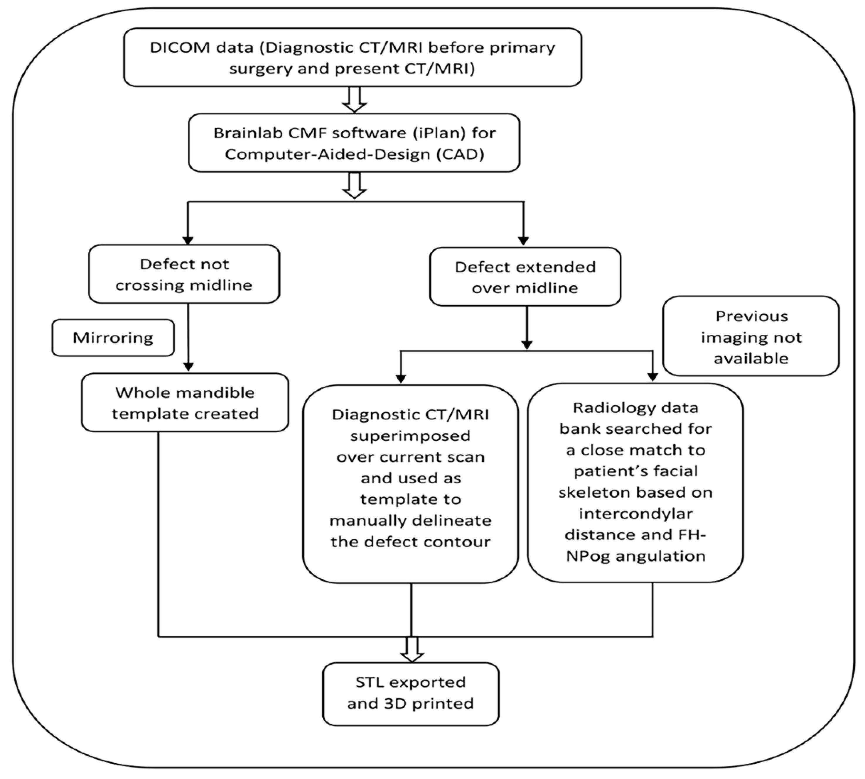
2.2. Virtual Planning Workflow
Brainlab CMF software (iPlan) (Brainlab, Germany) was used as the workstation for the planning pertaining to computer-aided design (CAD). DICOM (Digital Imaging Communications in Medicine) data of the CT/MRI of the primary lesion before ablative surgery was obtained from the institution’s radiology database if available. The virtual planning workflow is illustrated in
Figure 1. The advantage of the proposed algorithm is that it provides the readers with basic information on the virtual planning algorithm in addition to methods of achieving 3D template for printing the mandibular model in various defect scenarios.
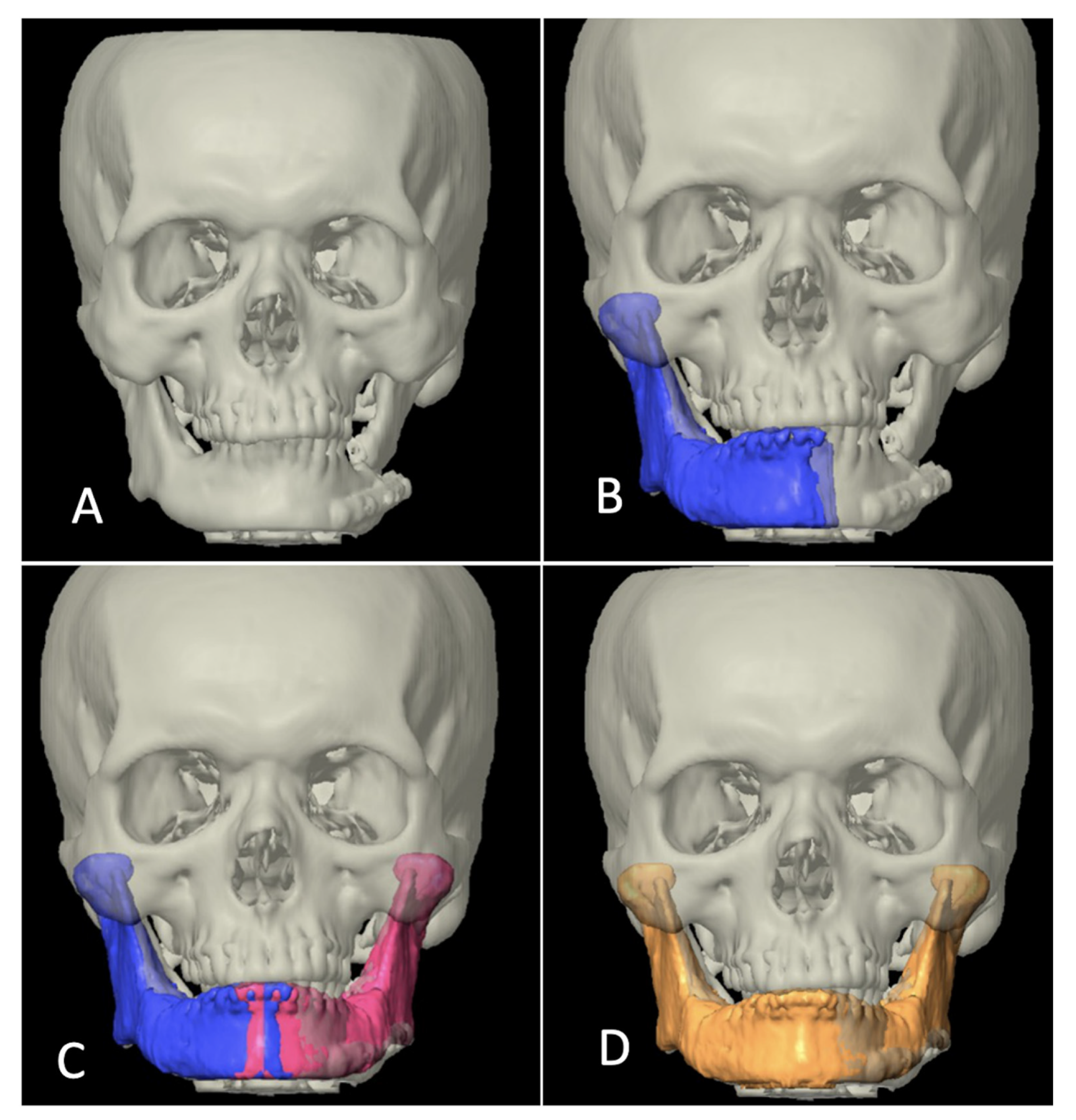
Category I included the cases where the reconstruction defect did not cross the midline. ‘Mirroring’ function integrated in the software was used to obtain the template of the defect from the normal sided mandible and whole mandible could be virtually constructed. Since the position of residual mandible is distorted in most of cases of secondary reconstructions, the residual mandible was also realigned to near-original position, taking occlusal relation as a guide and then mirroring it (
Figure 2).
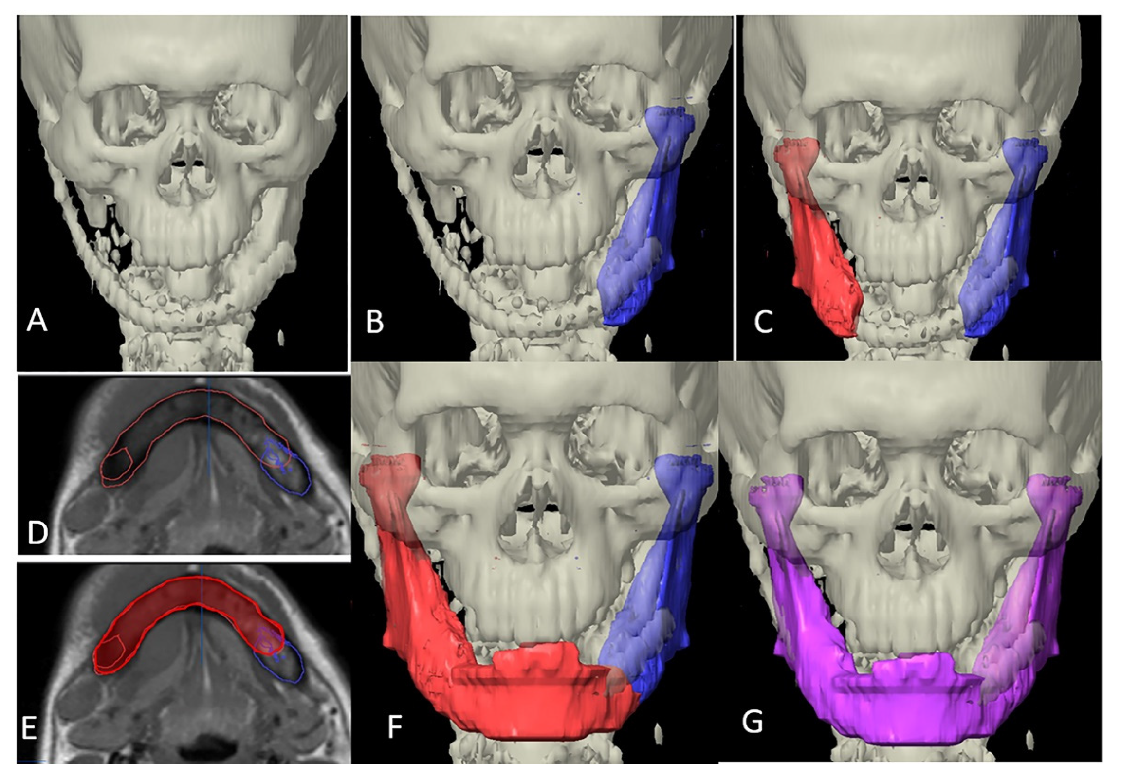
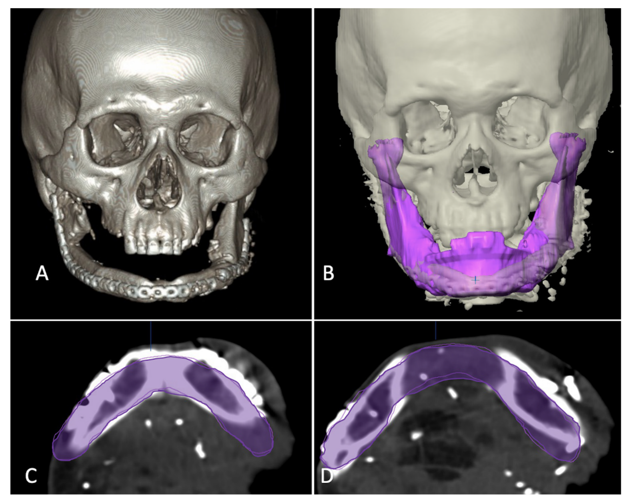
In category II, the ablative defect extended past the midline. CT/MRI taken before the primary surgery were superimposed over the postoperative/current imaging, necessary realignment of the residual segment was carried out and then mirrored. The unresected portion from the previous imaging was then used as template to manually delineate the mandibular contour to reproduce a whole mandible (
Figure 3).
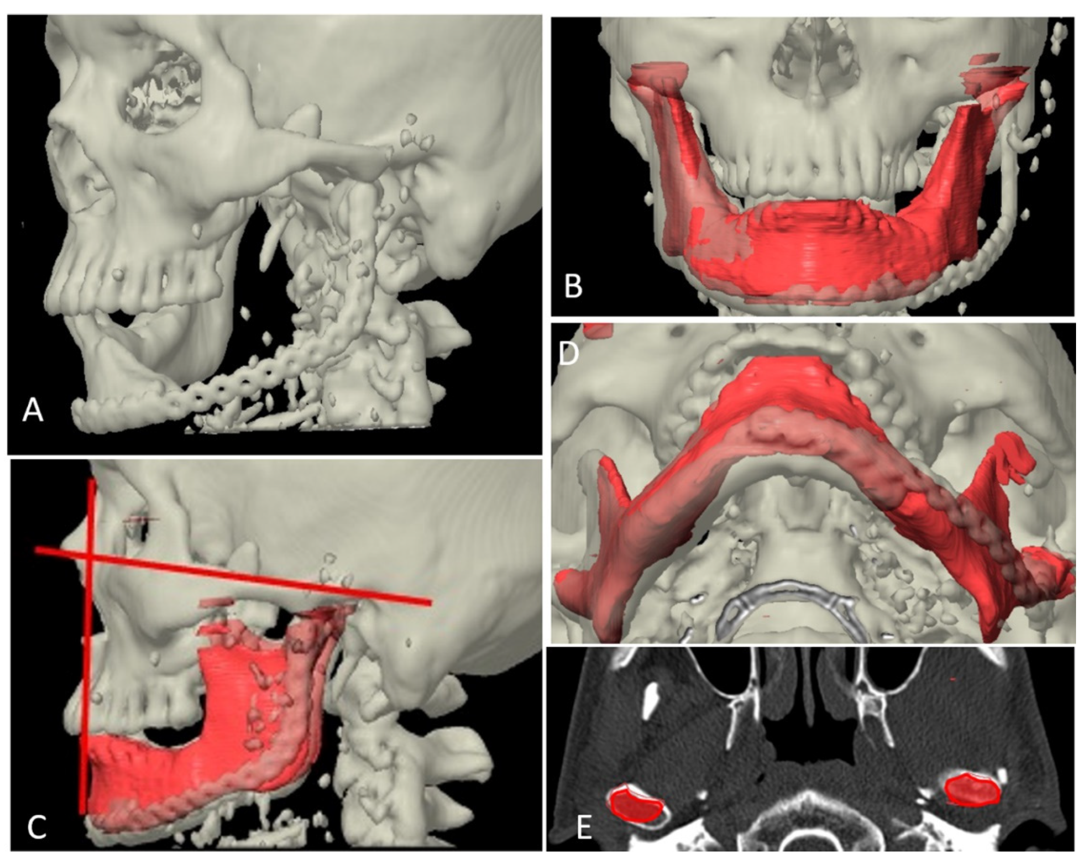
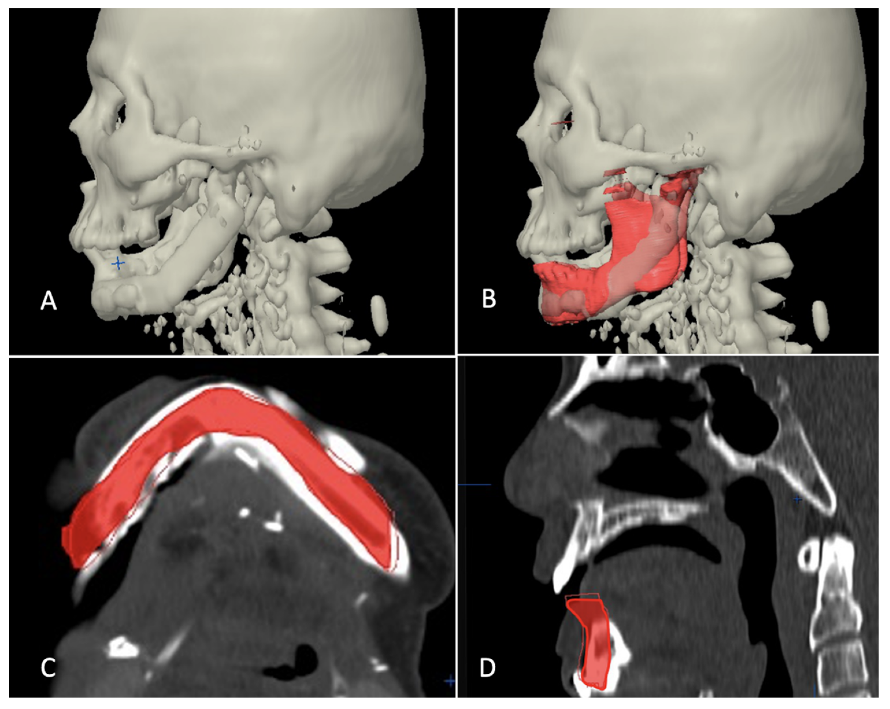
Category III included the cases where defect crossed the midline, but since primary surgery was carried out elsewhere, previous imaging data were not available. In those cases, the authors’ institution’s radiology data bank was manually searched for the mandibular anatomy that most closely mimicked the patient’s mandible in consideration for reconstruction. The inter-condylar dimension was taken as a reference for transverse dimension whereas a normal value of FH-NPog angle (angulation between Frankfort horizontal plane and Nasion-Pogonion line) was taken as a sagittal reference to look for a close match. It was also made sure that the mandibular arch form of the chosen data grossly coordinated with the maxillary arch form of the patient, i.e., in class I skeletal relation (
Figure 4).
In all cases, the reconstruction templates of various defects were 3D printed with medical grade printing material. The templates were cold sterilized and reconstruction plates were bent to the contour only after mandibular resection was completed so as to keep room for alteration in reconstruction plan as per the scenario on the table (
Figure 5).
2.3. Operation Technique
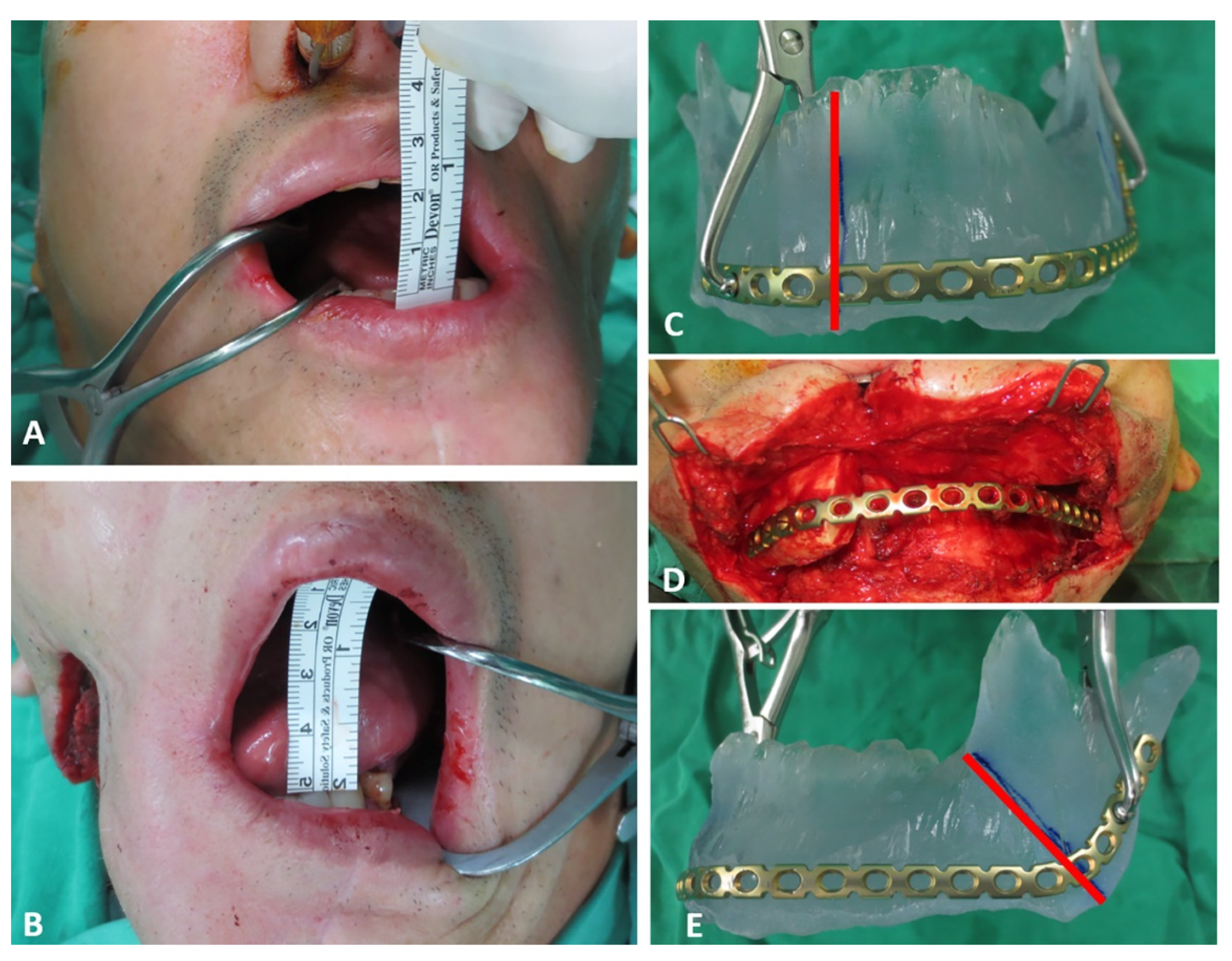
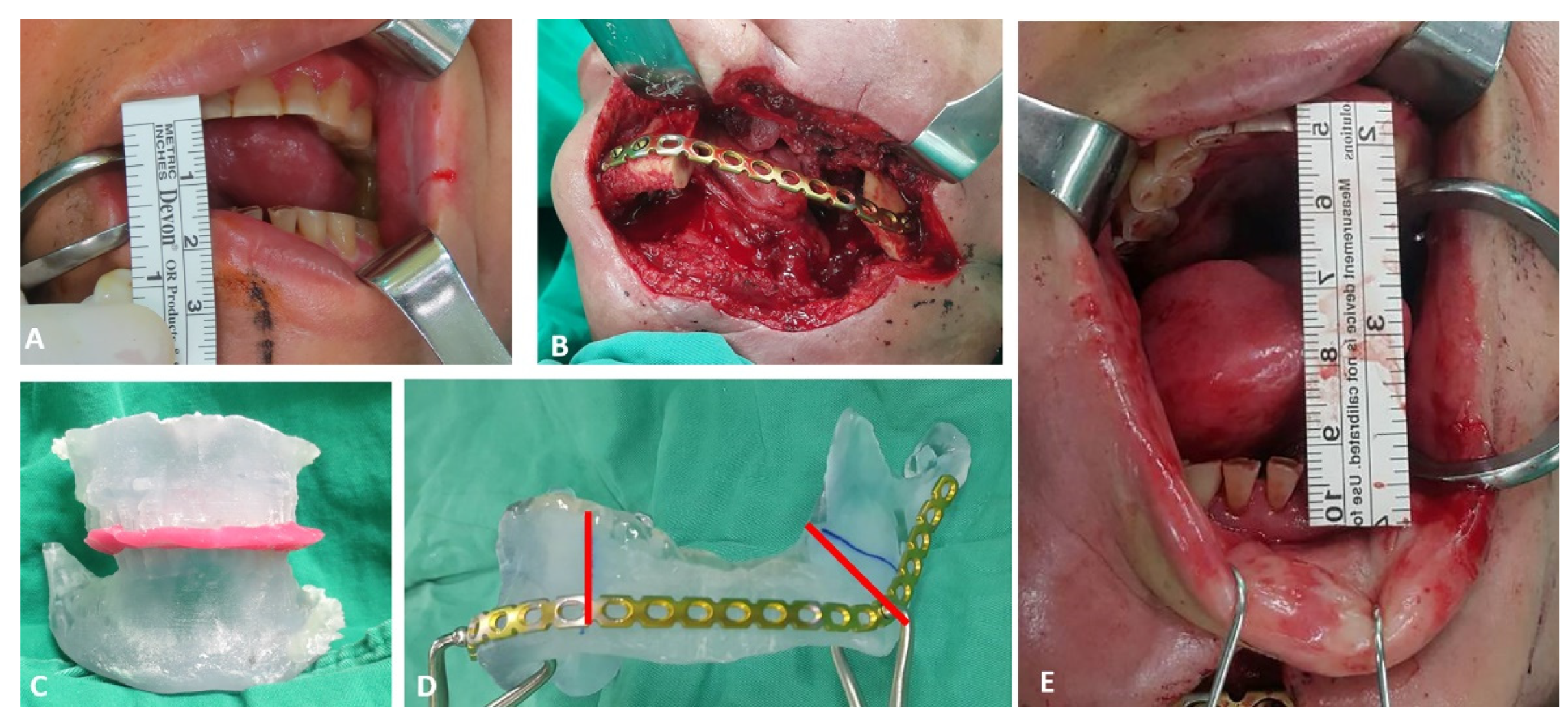
The 3D printed stereolithographic model generated via virtual planning workflow as discussed above was used as template for accurate bending of commercially available reconstruction plate into individualized shape. The scar from previous surgery was used for access, that was extended bilaterally to have adequate exposure of the remaining right and left mandibular segments. Subperiosteal dissection was then carried out to release fibrous adhesions around the displaced mandibular segment. Coronoidectomy was routinely performed to release temporalis contracture. Additionally, expansion of posterior pocket of ramus and removal of fibrotic tissues around bone were required to freely mobilize the remaining bone segments. Usually, after the contracture release, the mouth opening could be increased from around 10 mm to 45–50 mm (
Figure 6A,B and
Figure 7A,E).
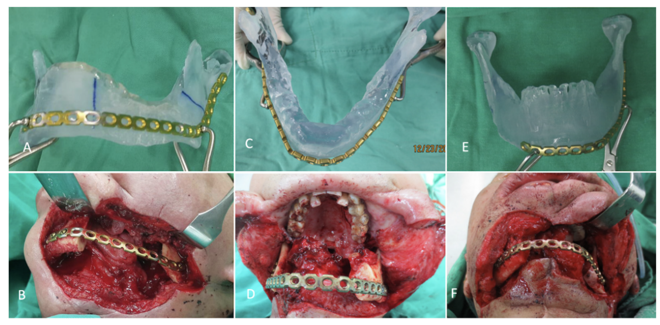
The individualized pre-bent reconstruction plate was then fixed to bilateral residual segments to restore the contour of original mandible. In order to precisely position the reconstruction plate as in 3D printed model, the following steps were adopted depending upon the dental status. In patients with enough teeth for occlusal guidance, the preoperative maxillary and mandibular model were printed out to fabricate the occlusal splint for intraoperative guidance. During surgery, the residual mandible segment was resected until bleeding from the bone margin was seen. The final resection margin was then marked in the 3D printed mandible model by measuring the distance from angle or mandibular notch of residual mandible (
Figure 6C,E and
Figure 7D). Now, the pre-bent reconstruction plate was placed in the model along the inferior and posterior borders, and at least three screw holes were marked on each residual mandibular segment. The center of these holes to the bone resection margin was measured with a ruler on the model and subsequently marked in the real mandibular segment. The occlusal splint with intermaxillary wiring was additionally used for precise placement of pre-bent reconstruction plate in this category (
Figure 7B,C). For edentulous patients, the pre-bent reconstruction plate was fixed to the residual mandible segment with the guidance of the marked center of three holes (
Figure 6D).
The fibular osseoseptocutaneous flap was harvested at the same time during the trismus release and mandible contour restoration by individualized reconstruction plate. The fibula was osteotomized by the ruler template method with at least 3 cm in each segment to ensure adequate bone perfusion [
12]. Fine burring was carried out to make sure tight contact existed between resected mandibular margin and fibula osteotomy site so that proper bone healing was ensured.
2.4. Evaluation of Accuracy of Planning
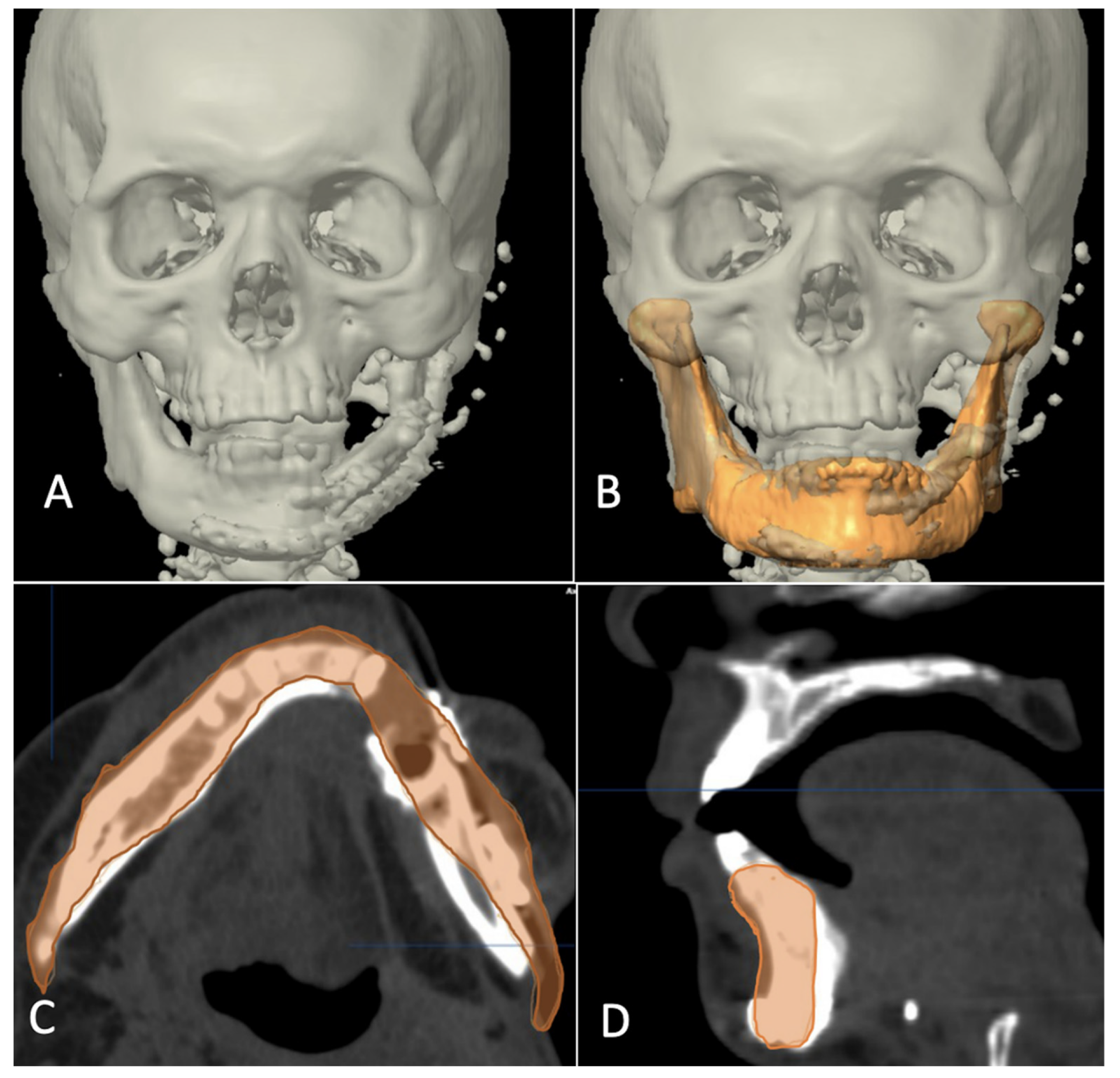
The evaluation phase in postoperative period started with a repeat CT scan after six months of reconstructive surgery and involved superimposition of postoperative images with virtually reconstructed mandible in the computer planning (
Figure 8,
Figure 9 and
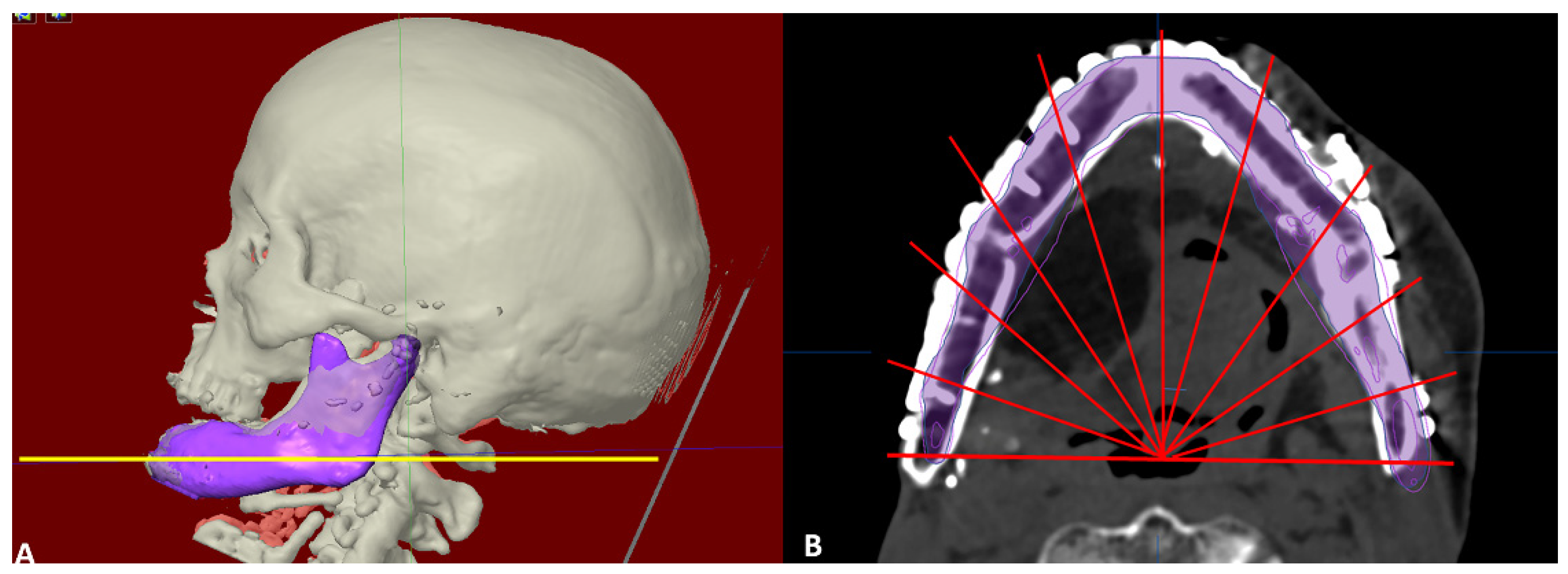
Figure 10). The 3D craniofacial image was reoriented with counterclockwise pitch rotation to allow the whole mandible from the right to the left angle be seen in one axial 2D view. In the 2D view, a section through the mid-way of chin and parallel to the lower mandibular border was selected for measurement (
Figure 11A). The entire length was divided into ten segments, each separated with an angulation of eighteen degrees from the base line joining the two angles, resulting into 11 points of measurement (
Figure 11B). The linear discrepancies between virtually planned position and the buccal aspect of actual bone position were measured. The mean differences in the distance and the standard deviation were consequently calculated. The differences in mean between the three categories were also calculated to compare the accuracy of reconstruction.
2.5. Statistics
Statistical Package for Social Sciences (SPSS) version 17.0 (SPSS Inc. Chicago, IL, USA) was used for relevant data analysis. Kruskal-Wallis Test was used as non-parametric method to compare among three groups and Mann-Whitney U test was used for comparing between two groups.
For confirmation of the measurement reliability and repeatability, the difference between the postoperative and virtual planning image were evaluated by two individuals. To evaluate agreement between the two, an intraclass correlation coefficient (ICC) was calculated by using a two-way mixed model. The ICC represents the proportion of the total variability in each measurement that can be attributed to the true variability among individuals. It assumes values from 0.0 to 1.0, with values of 0.00 or lower considered poor; greater than 0.00 to 0.20, slight; 0.21 to 0.40, fair; 0.41 to 0.60, moderate; 0.61 to 0.80, substantial; and 0.81 to 0.99, almost perfect agreement.
3. Results
Total of eleven patients underwent secondary reconstruction of mandible during the study period. There were ten males and one female with a mean age of 59.4 ± 5.3 years. Five of them fell into the category I (defect not crossing the midline), three of them were category II (defect extending past the midline with availability of previous imaging data) and three of them were category III (defect extending past the midline but with unavailability of previous imaging data). The patients presented for secondary reconstruction after a mean duration of 2.7 years ± 0.8 years. The mandibular defects in the patients as per HCL classification [
13] (H: Hemimandibular defects i.e., mandibular defects including the condyle not crossing the midline, C: Central defects covering canine to canine region, L: Lateral defects i.e., mandibular defects sparing the condyle and not crossing the midline) included six lateral defects/L, three lateral defects combined with central defects/LC and two right and left laterals combined with central/LCL. The reasons for secondary reconstruction were osteoradionecrosis in five patients, reconstruction plate exposure in one and second stage reconstruction of post ablative defects in five of them (
Table 1).
The mean linear discrepancy between the planned and post-operative position was 1.43 ± 1 mm in category I, 1.72 ± 1.29 mm in category II and 4.92 ± 3.8 mm in category III. The Kruskal-Wallis Test showed a significant difference among three categories. The Mann-Whitney U test was carried out to further compare mean discrepancy between any two categories and it showed no significant difference between group I and group II (p > 0.05) whereas comparison of groups I and II separately with group III showed a significant difference (p < 0.01). Guided by the observation, mean discrepancy values between L/LC defects (1.99 ± 1.34 mm), and LCL defect (5.98 ± 4 mm) was analyzed, which showed a significant difference (p < 0.05). Such an observation would imply that the proposed and described algorithm of template printing might be less accurate in huge bilateral mandibular defects. The ICC between two individuals was 0.89 which confirmed almost perfect agreement for inter-rater reliability of analysis.
4. Discussion
Various modalities of use of load bearing plates during reconstruction of mandibular defects have been discussed in the literature. The most common of them are: (i) manual bending of straight reconstruction plates as per the defect; (ii) commercially available preformed plates; (iii) reconstruction plates that are prebend over a template obtained from 3D printing; and (iv) use of patient-specific 3D printed reconstruction plates aided with cutting guide, drill guide and positioning guide. Bending of plate on the table as per defect may sound simple but can pose difficulty in accurately conforming the plates when defects are long. Factory manufactured preformed plates do ease the job of manual bending but may not always perfectly match the individualized mandibular contours [
13,
14,
15,
16]. Patient specific implants have been viewed as a promising modality for primary bone defects and benign conditions [
17,
18,
19]. Theoretically, this approach has the maximum accuracy of the reconstruction. However, they do not offer any room for surgical flexibility [
1,
2]. Any change in the surgical plan or resection margins during intraoperative period would simply discards their usage. This not only adds cost to the patients but also frustration to the surgeon.
The goal of computer assisted planning in head and neck tumor surgery is to increase surgical accuracy, to achieve better aesthetic and functional outcomes, decreased intraoperative and graft ischemia duration, and to make the overall learning curve easy, producing consistent results [
20,
21,
22]. There is definitely an advantage of CAD/CAM planning over conventional surgical methods. However, translating the accurate virtual planning to operating table is a still a big challenge. This issue becomes more crucial when we talk about reconstruction of complex craniofacial defects, especially secondary bone defects after radiotherapy or extensive lesion crossing the midline [
4,
12]. The authors have discussed the use of CAD-CAM technology to design and manufacture mandibular template in various secondary defect configurations for the purpose of patient-specific manual plate bending. To the best of the authors knowledge, this is the first attempt to propose an algorithm to virtually design a defect template in various defect configurations and clinical scenarios by use of Brainlab CMF software (iPlan). Nobis et al. had performed anatomical measurements in 100 CT scans and suggested that development of a mandibular reconstruction template tool would benefit mandibular reconstruction patients due to a constant mandibular arch angle and symphysis segment length throughout the general patient population, allowing the mimicking of a mandibular arch with up to three fibula segments [
23].
The standard protocol devised by the authors and discussed here, attempts to fabricate model templates as close as possible to the patient’s native mandible in various defect scenarios. The reconstruction plates are then manually bent on the operating table depending upon the defect created. Following the presented approach and protocol, the mean linear discrepancy between the planned and post-operative position was 1.43 ± 1 mm in category I, 1.72 ± 1.29 mm in category II and 4.92 ± 3.8 mm in category III. The values in category I and II are in line with the accuracy studies in previous similar studies, if not better [
7,
24,
25,
26]. Moreover, the comparison of accuracy result among the category I and II did not show significant differences in the mean discrepancies between the virtual plan and the result. This provides a reliable base to use the proposed algorithm in the mentioned clinical scenarios.
However, we observed that the linear discrepancy values in category III seemed a bit at larger side (i.e., 4.92 ± 3.80 mm). Category I and II also showed significant difference in the mean discrepancies with category III. Looking at the defect types in this category, two patients had LCL defect and one had LC defect. The difference in discrepancy values between relatively smaller mandibular defects (L/LC) and larger defects (LCL) was also studied. The former group had nine patients from categories I/II/III whereas the latter group had two patients under category III. It was an interesting finding to note that the mean discrepancy value in L/LC defects was 1.99 ± 1.34 mm and that in LCL defects was 5.98 ± 4 mm; the difference being statistically significant. This somehow leads to an observation that the accuracy difference of manual plate bending protocol presented here might not be implicated to categorical differences but to defect size (i.e., huge bilateral mandibular defects (ramus/condyle to ramus/condyle)) showed lesser accuracy results as compared to smaller defects (L/LC). Several factors could be attributed to the decreased accuracy results in LCL defect. Firstly, angle to angle or condyle to condyle mandible reconstruction plate is not commonly available. Thus, two mandible reconstruction plates were assembled for reconstruction of larger defect and this kind of assembly can easily lead to the loss of accuracy. Secondly, the small residual parts comprising of bilateral condyle or ramus cannot be stabilized easily to reconstruction plate which can also lead to the inaccuracy in reconstruction. Thirdly, it would also be worthwhile to understand that due to severe scarring and contracture, the soft tissue will not react predictably to the underlying skeletal reconstruction as it would seem in primary cases. Nevertheless, the method of patient-specific manual plate bending would still be justified in those cases where patient-specific 3D printed plate options are not available or affordable, since it certainly avoids subjective guesswork in plate contouring. The two patients with LCL defects are still satisfied with the outcome of reconstruction since they finally received a chin in place of “Andy Gump” deformity.
A number of studies have attempted to devise mandibular reconstruction protocol using CAD/CAM technology and evaluated the accuracy of plan as well [
7,
24]. A study by Hanasono and team found a significant reduction in surgical time, significant change in mean values of selected bony landmarks when comparing computer assisted designs and rapid prototype modelling with conventional manual methods. Comparison of post-operative mandibles with virtual plans showed a mean deviation of 2.40 ± 2.06 mm in fibular lengths [
27]. In 2016, Lei et al. too evaluated the accuracy of computer assisted mandibular reconstruction with free fibula flap in 8 patients versus 14 patients with conventional manual intervention. Their results showed a deviation in fibula length segment of 1.34 ± 1.09 and angular deviation of 2.29 ± 1.19 degrees. The mean differences in intercondylar distance, intergonial angle distance, anteroposterior distance, gonial angle, and duration of ischemia were all improved in the computer assisted group as compared with the conventional surgery group [
28]. The accuracy measurements in category I and II in present study are in line with the findings in studies discussed.
Although the accuracy, precision and reduced operative time has been attraction of computer-assisted planning in head and neck reconstruction, the technique is not without limitations. Wei et al. in their study on computer-assisted surgery for segmental mandibular reconstruction stated that the location of osteotomy site and the design of skin paddle might change on the table and differ from virtual plan since the status of surgical margins is important, the precise determination of which is not always possible from imaging [
10,
29]. Even if it is true that the extent of the lesion can be visualized on the three-dimensional model to determine resection sites, it might only be possible for tumors and not for cases of osteoradionecrosis, in which bone quality assessed clinically usually determines resection margins [
29]. Wilde et al. in their multicenter study reported that insufficient guide design or inaccurate guide fits will inevitably lead to intraoperative difficulties in positioning the guides and thus to reconstruction inaccuracies [
19]. Thus, the importance of flexibility during surgery cannot be overlooked and an approach that welcomes surgical flexibility and provides accurate reconstruction at the same time would serve beneficial in such scenarios. The facts and findings from the studies discussed above justifies the technique of patient specific manual plate bending discussed in the present study.
In a recent publication, issue has been raised regarding formation of biofilm in 3D printed customized titanium reconstruction plates and commercially available plates. 3D- printed plates showed higher roughness than commercial plates. All strains of bacteria colonized 3D- printed raw plates more densely than commercial plates. Although this finding supports use of factory manufactured stock plates, the obvious loss of anti-corrosive layer during plate bending and cutting happens to be a major drawback of commercial plates [
26].
The approach discussed and the protocol devised is easy to follow and the cost of procedure is significantly reduced as compared to 3D printed patient specific implants. Although the patient-specific pre-bent plate via the template printing will not be able to catch up with the optimal accuracy offered by 3D printed patient-specific implant plus cutting, drilling and positioning guides, it definitely provides greater degree of surgical freedom in cases of osteoradionecrosis as well as good and acceptable accuracy for L/LC and LCL defect reconstruction, respectively. The retrospective nature of the study with limited sample size remains a major limitation. However, the protocol discussed does pave a way for organized prospective studies with larger samples in the future.


