
Integrated System for Official Vehicles with Online Reservation and Moving Path Monitoring

Abstract
:1. Introduction
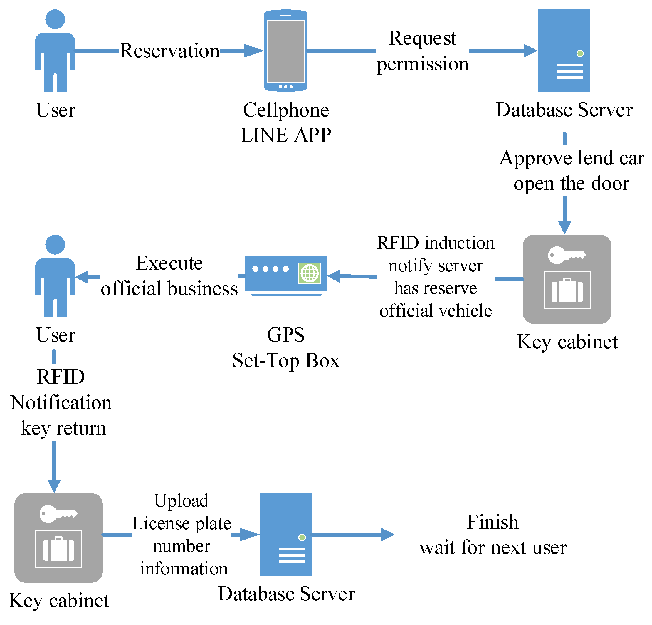
2. System Architecture
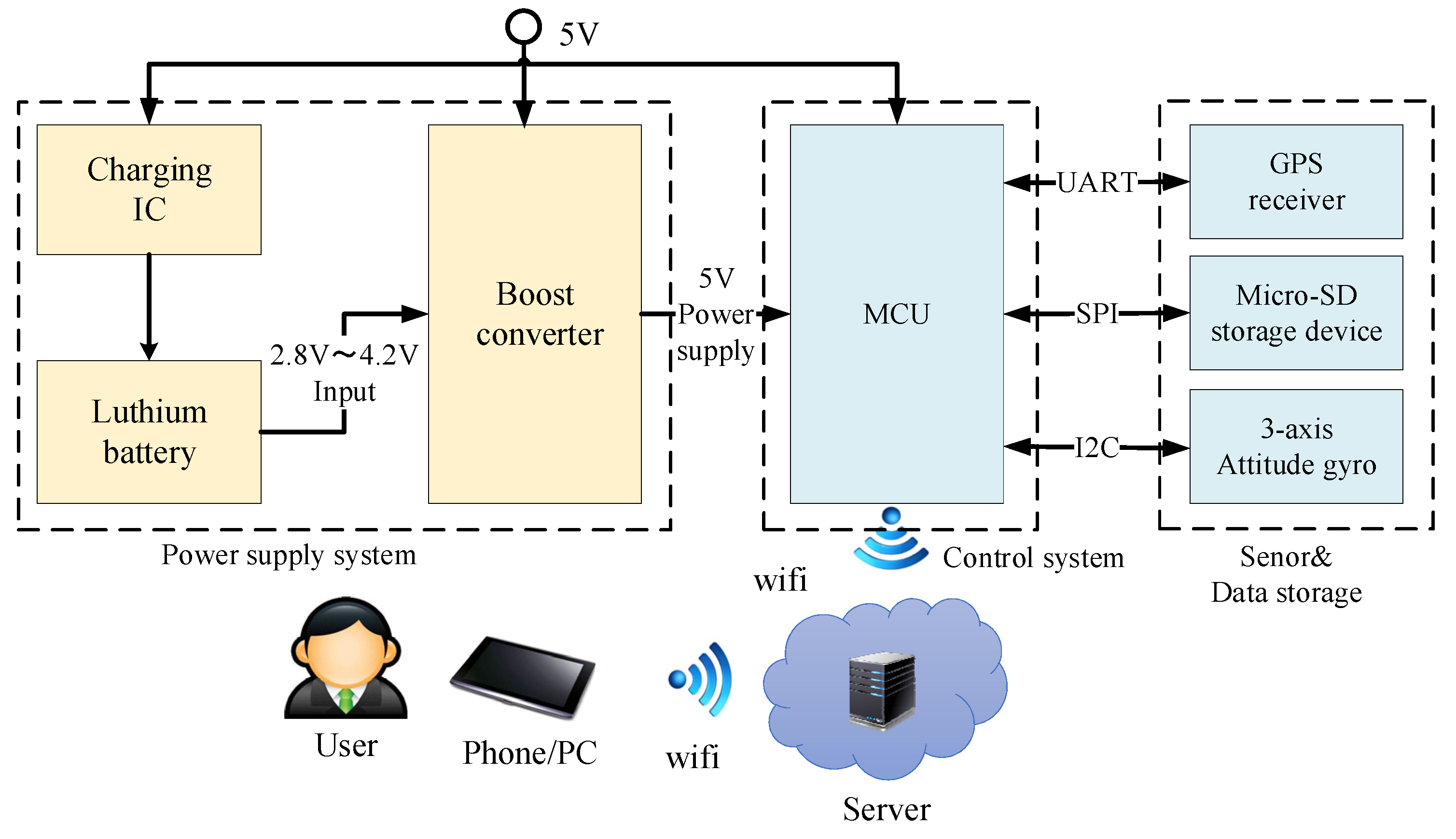
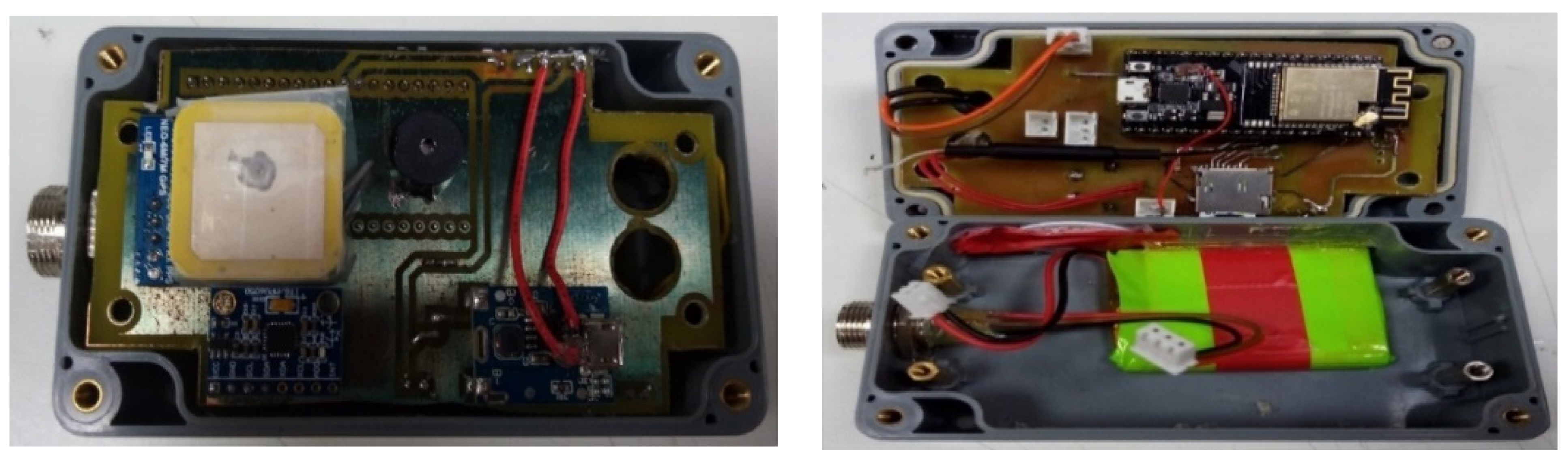
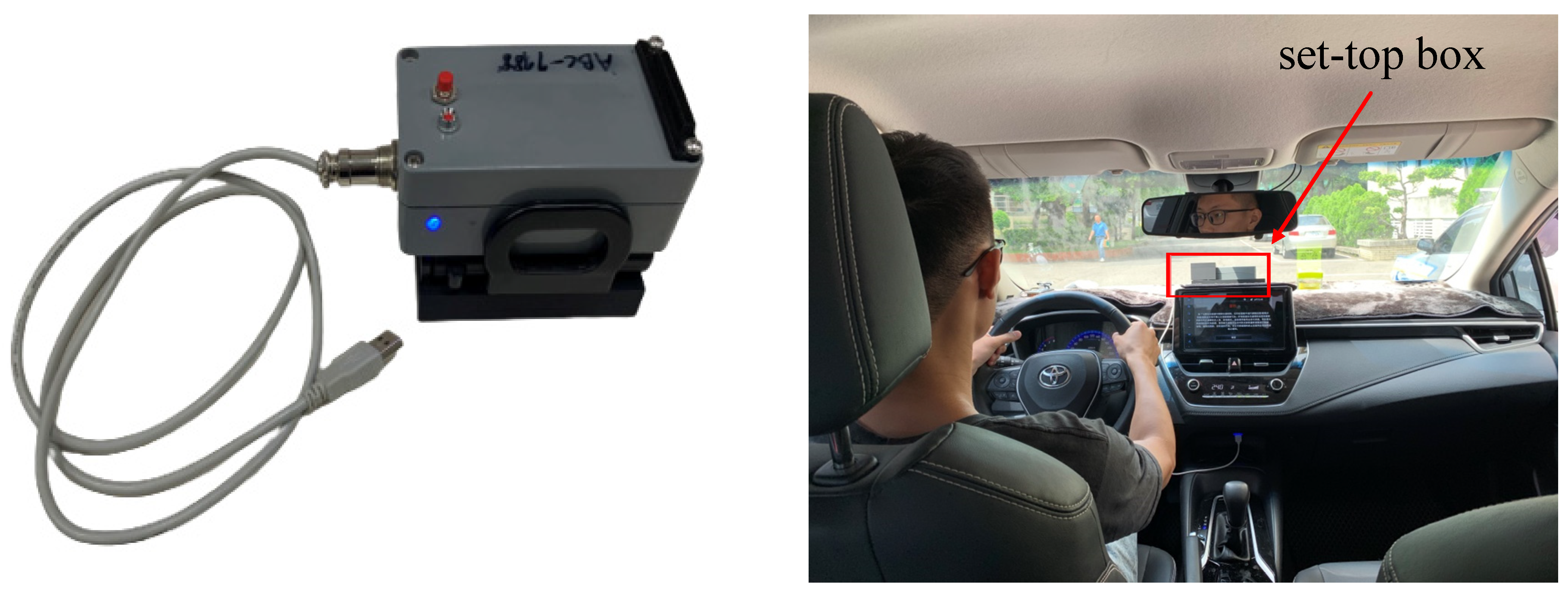
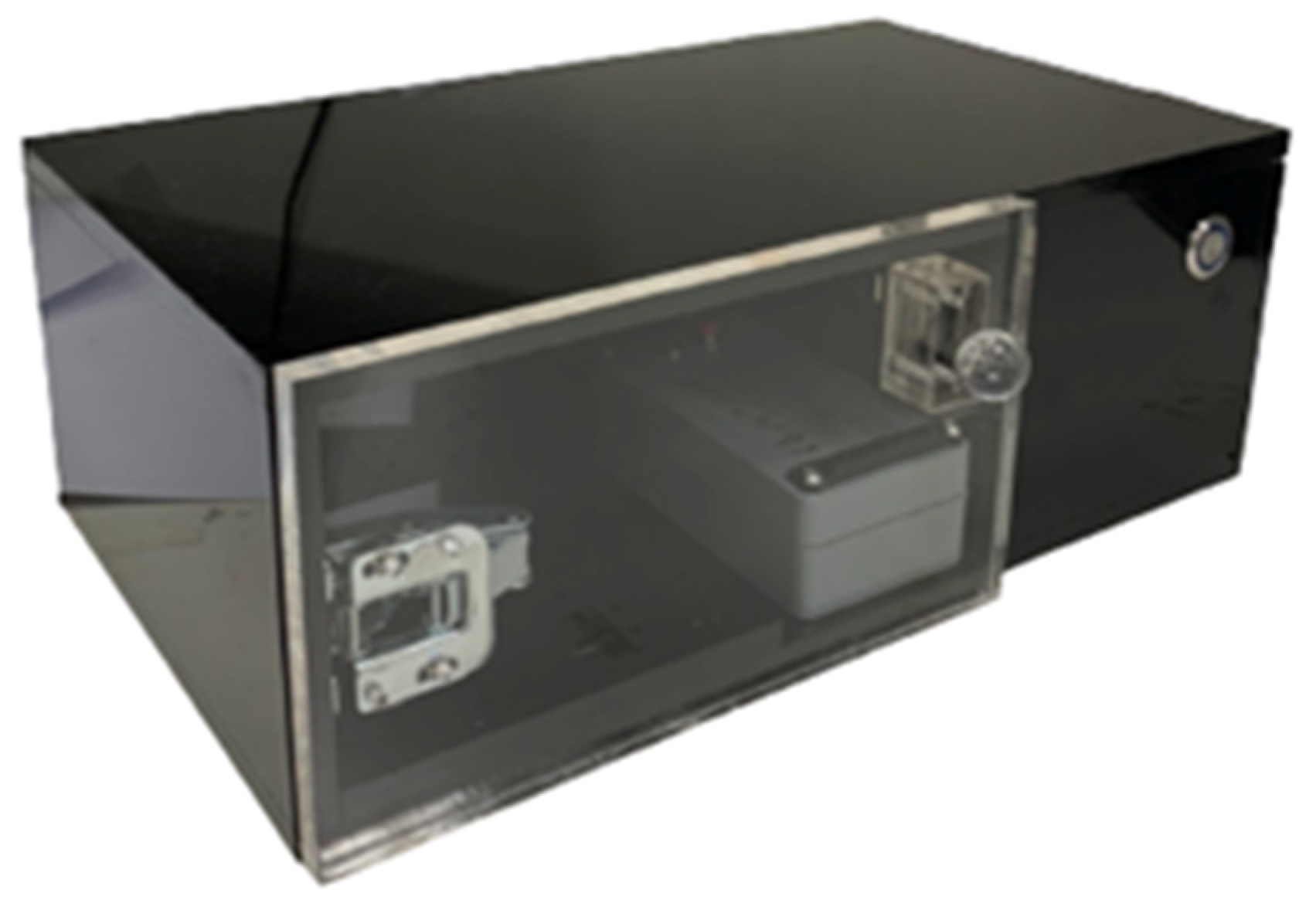
2.1. Set-Top-Box (STB)
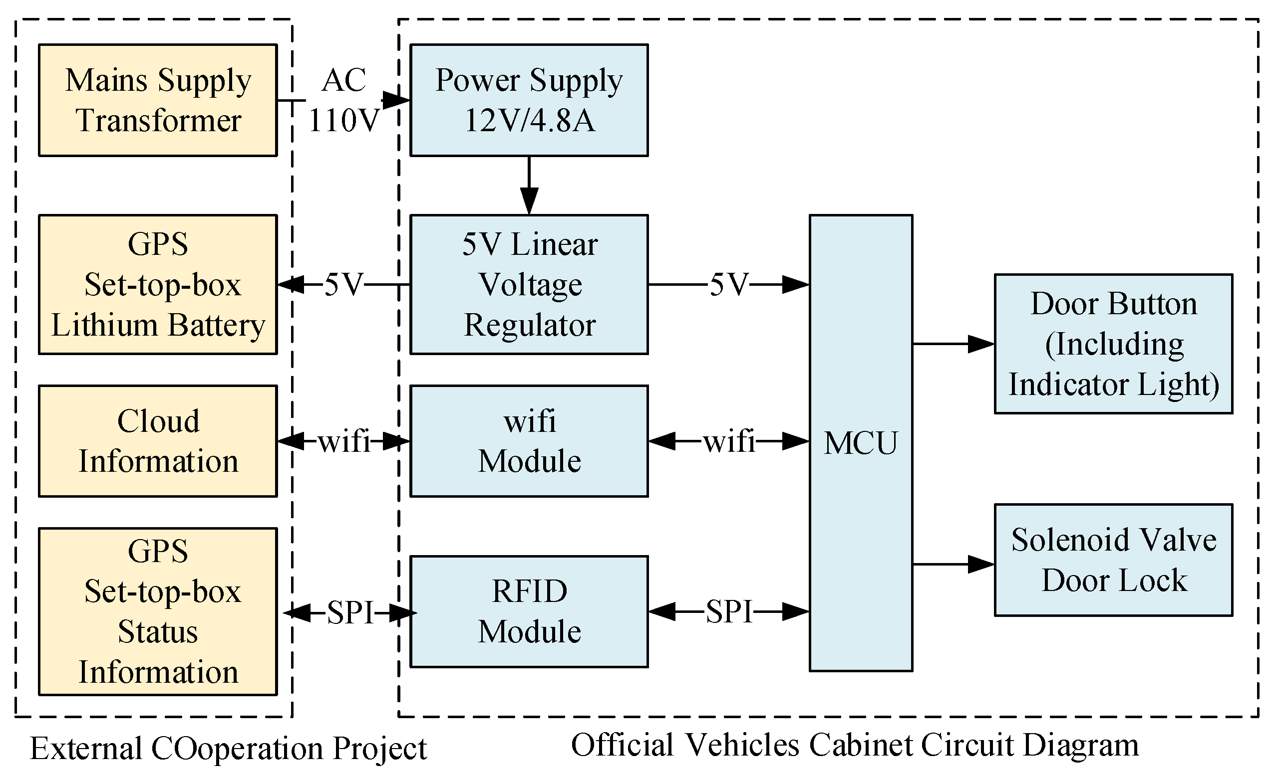
2.1.1. Power Supply Module
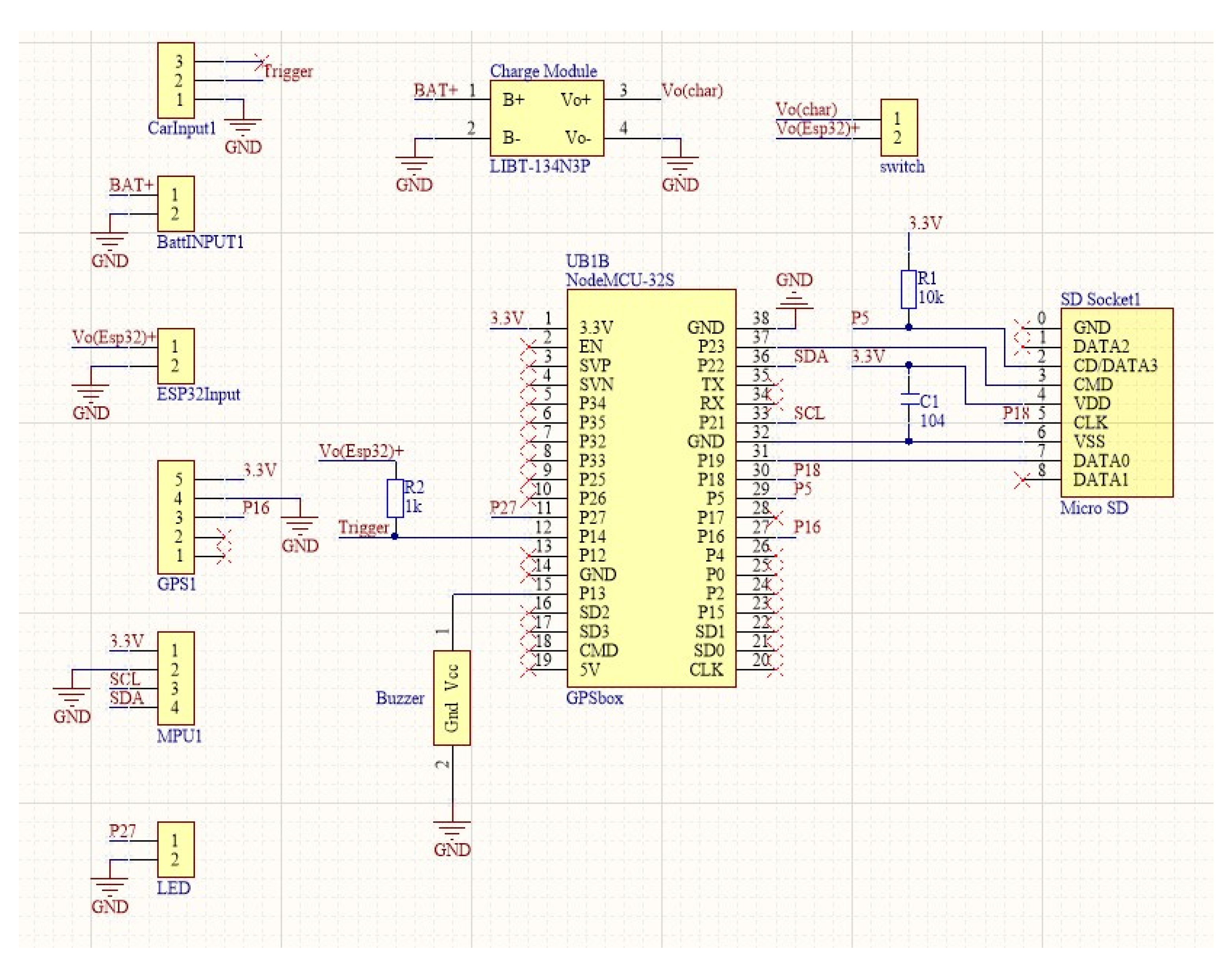
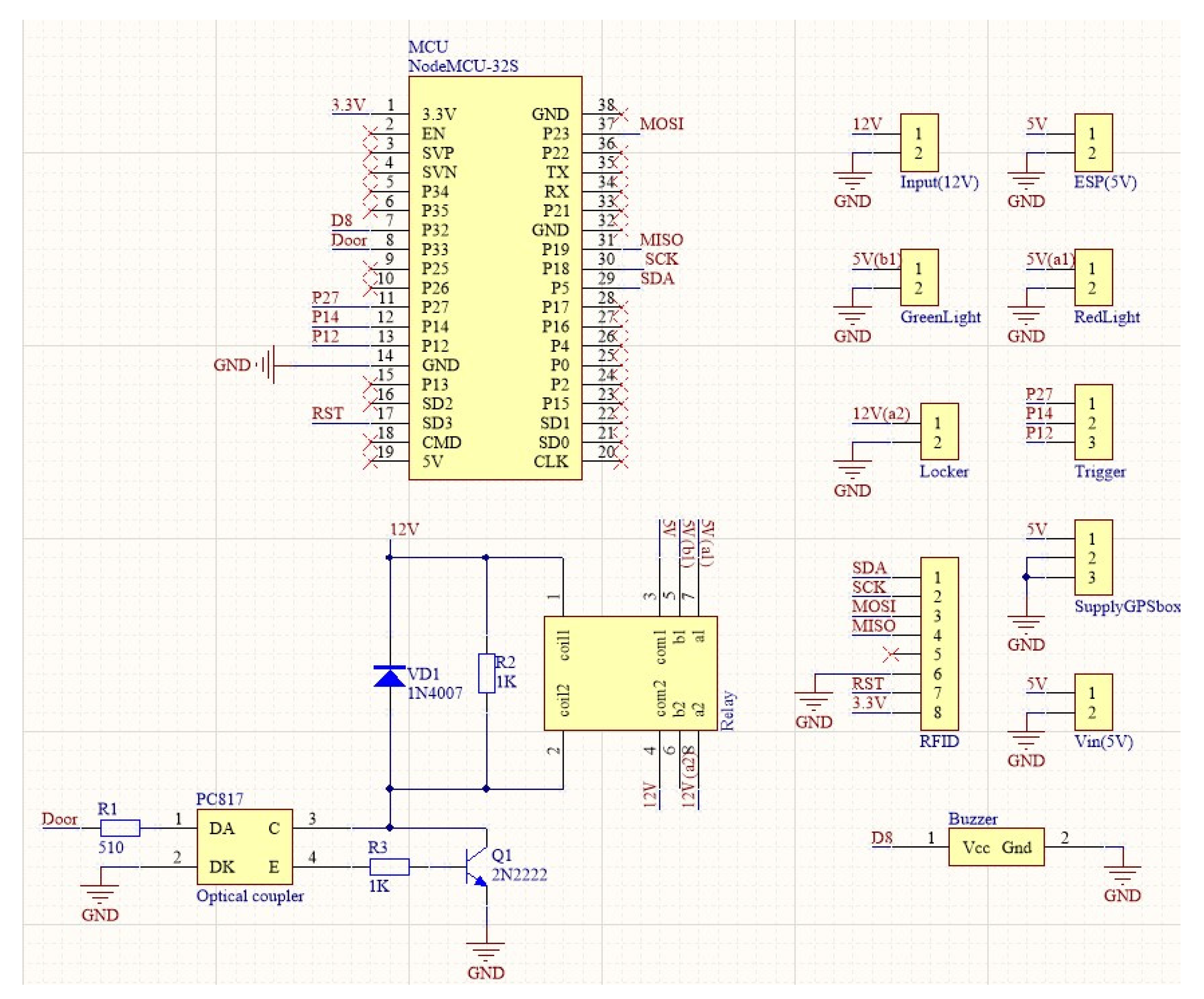
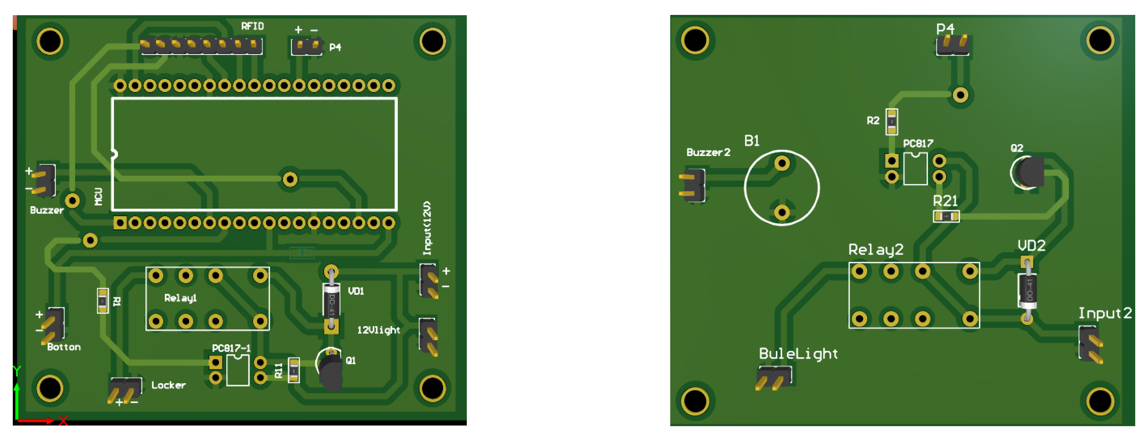
2.1.2. Control System
- (a)
- The MCU has a dual-core CPU with a working clock of 160/240 MHz, 448 KB of ROM, and 520 KB of SRAM. It supports 802.11 b/g/n transmission protocol. It has a total of 34 GPIOs externally, and multiple communication interfaces such as SPI, I2C, and UART enable communication with multiple different sensors or devices.
- (b)
- The GPS receiver uses the interface protocol developed by NMEA for three specifications: 0180, 0182, and 0183. The NMEA-0183 protocol is used in detectors, sonars, anemometers, GPS receivers, and other devices. The transmission data are encoded in ASCII code, and its communication format is shown in Table 1. Each statement has a different length, and the longest bit is up to 82 bits. In this study, the sentence at the beginning of GPRMC is used for analysis. Thus, the content of each sentence group such as the current latitude and longitude, hemisphere, and UTC is separated by commas. A sentence starts with $, and the CR and LF codes of ASCII are used as the end code of the sentence. The code is stored in the micro-SD memory card after processing the character strings.
- (c)
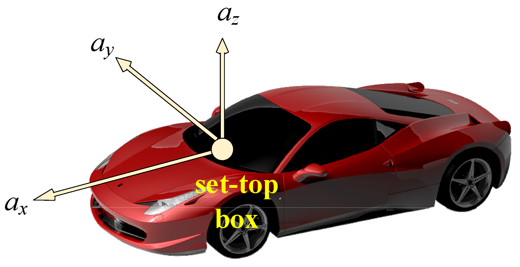
- Accelerometer and gyroscope
- (d)
- SD card storage device
- (e)
- Cloud server
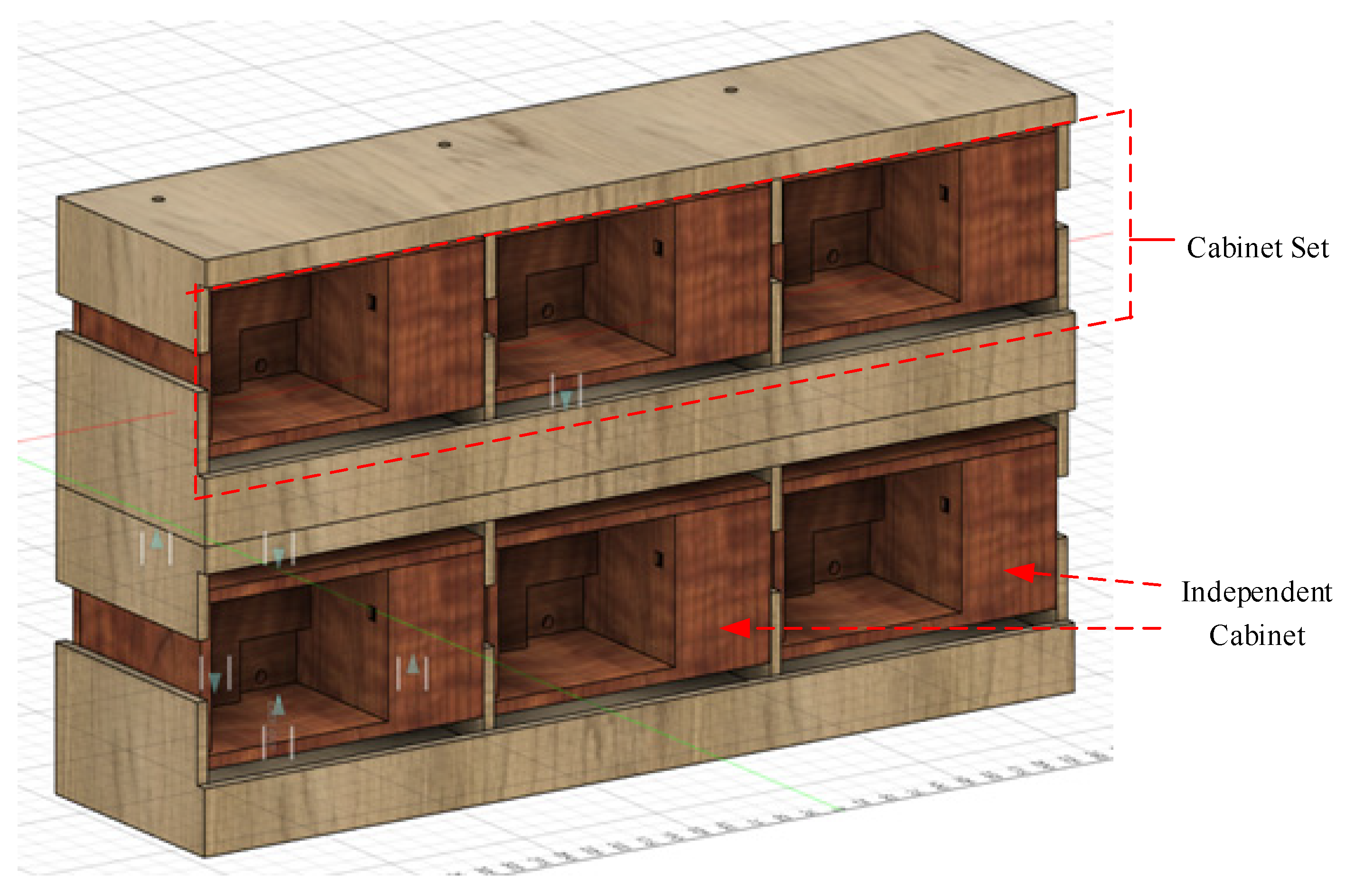
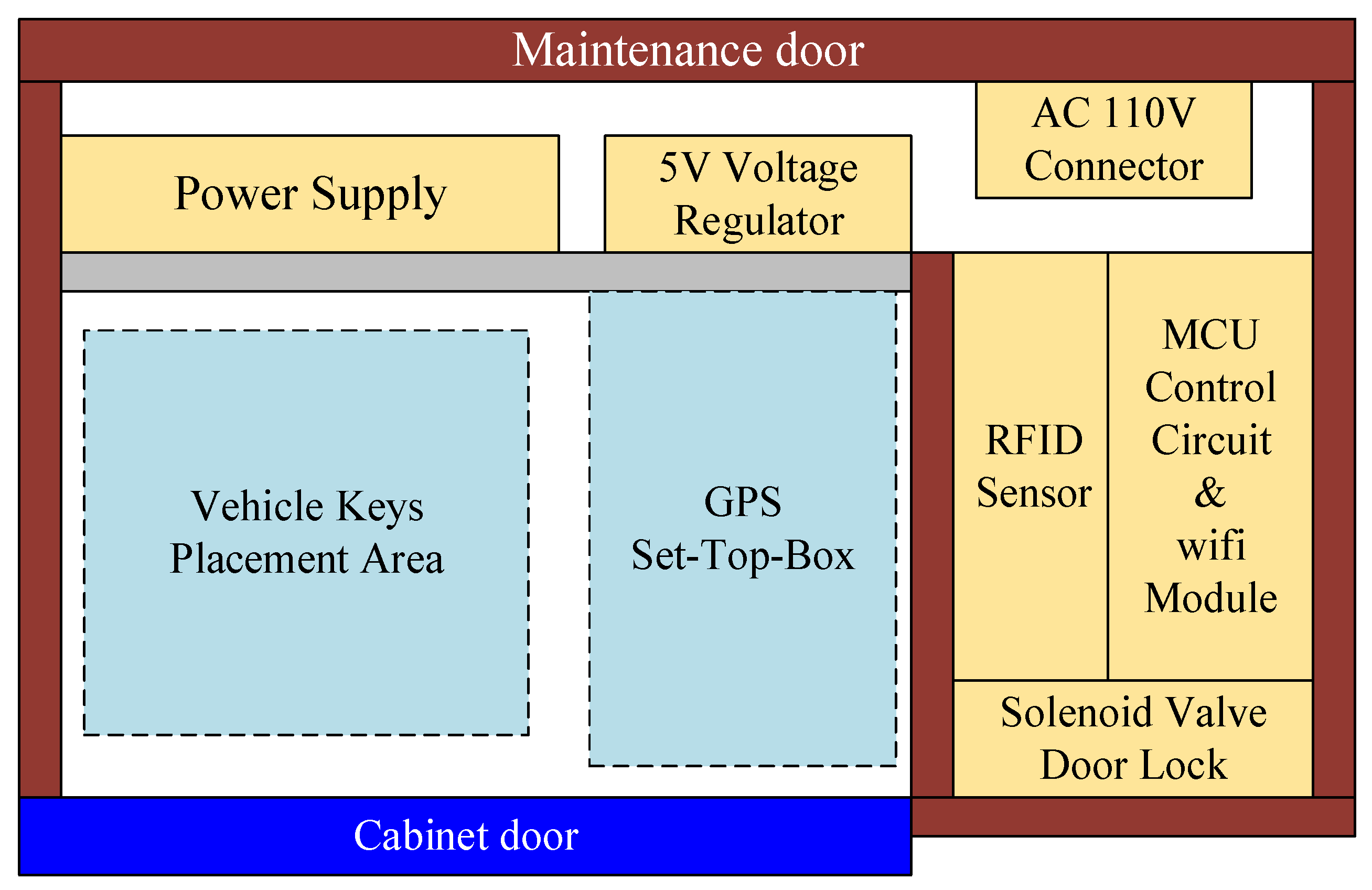
2.2. Key Cabinet
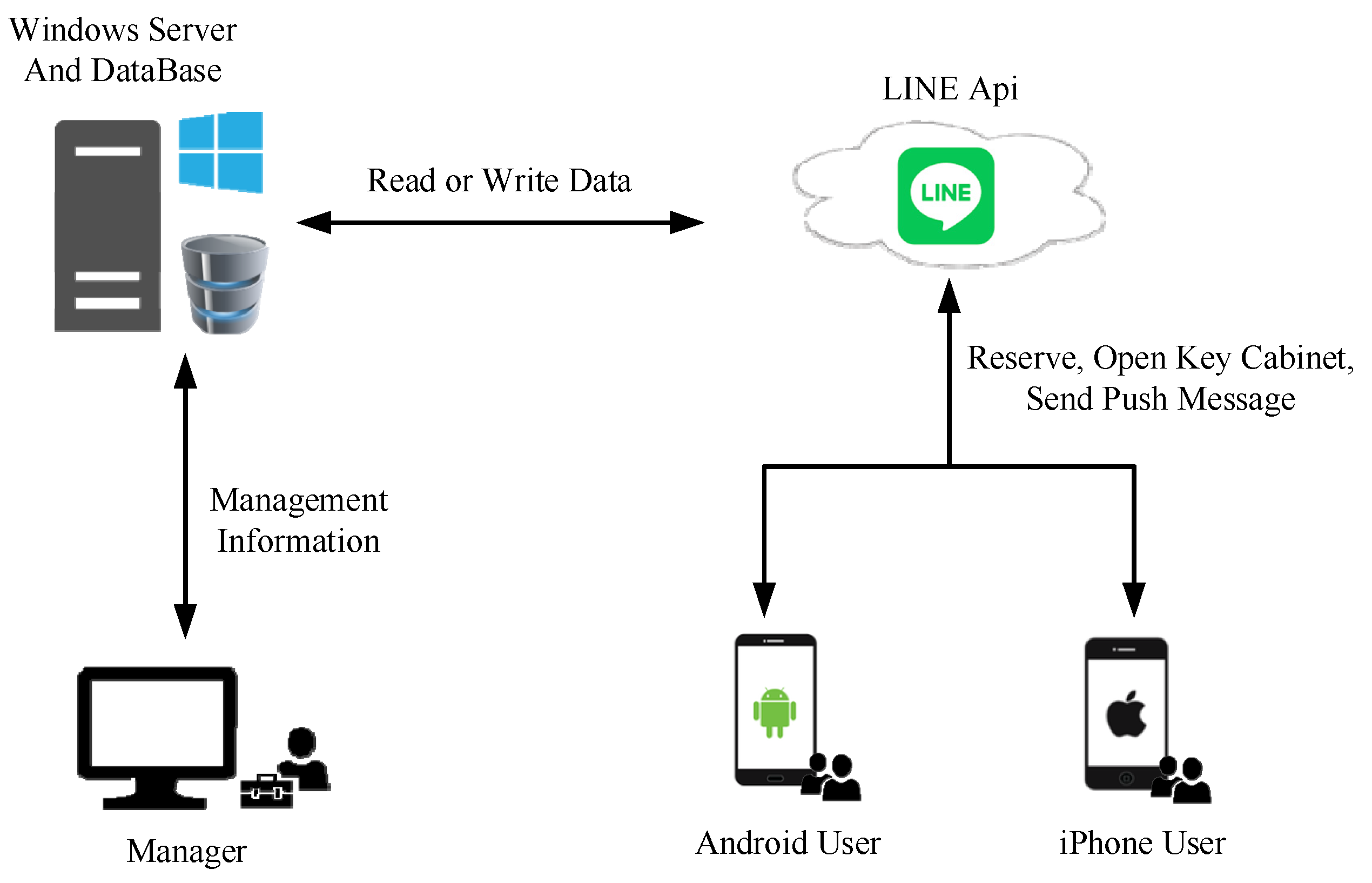
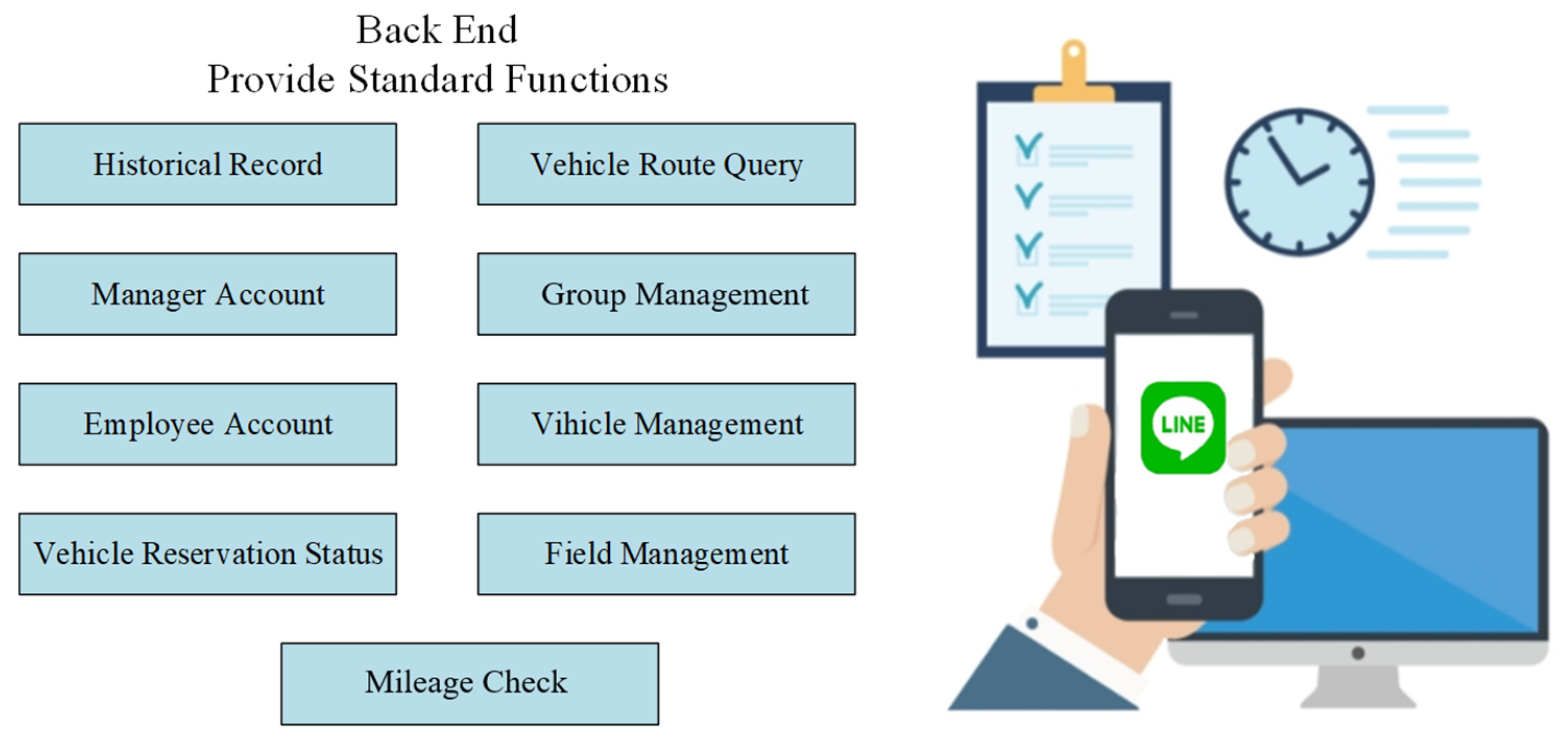
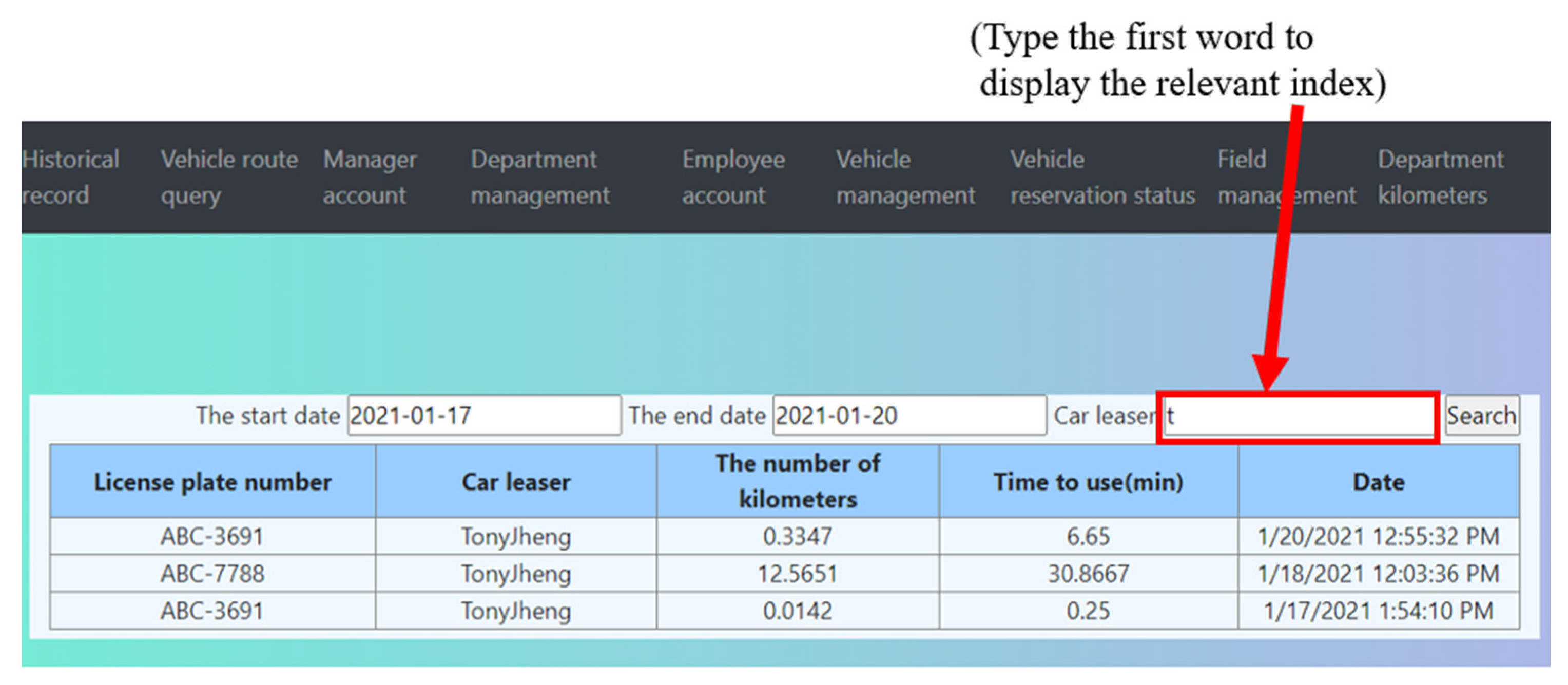
2.3. Cloud Server
- (a)
- Historical records such as date, user name, the license plate, number of uses, and period of use;
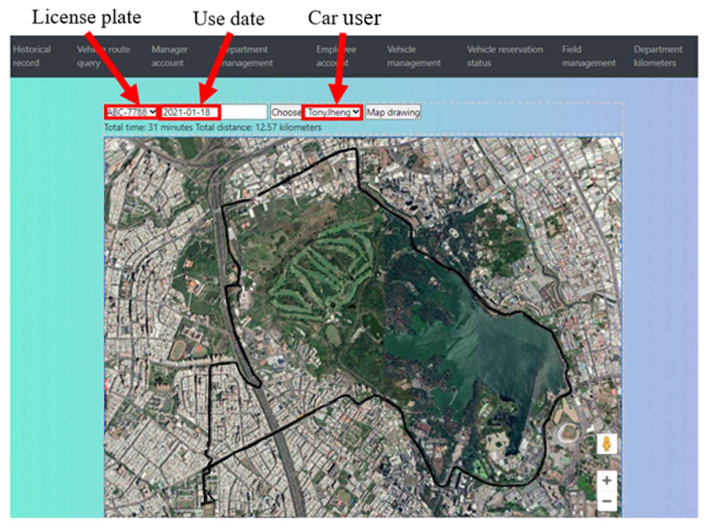
- (b)
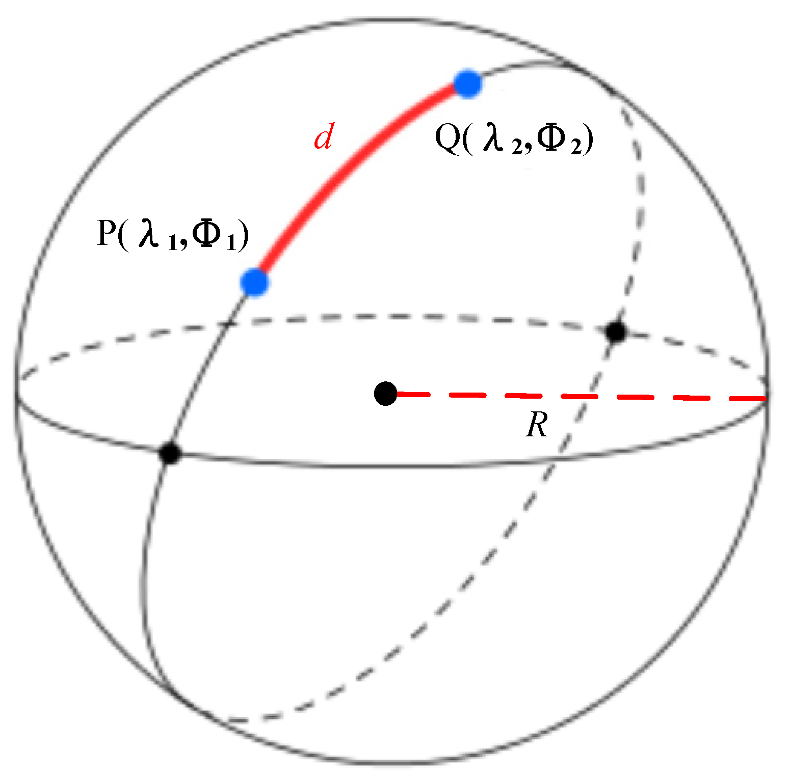
- Vehicle route query for total time and distance of a trip;
- (c)
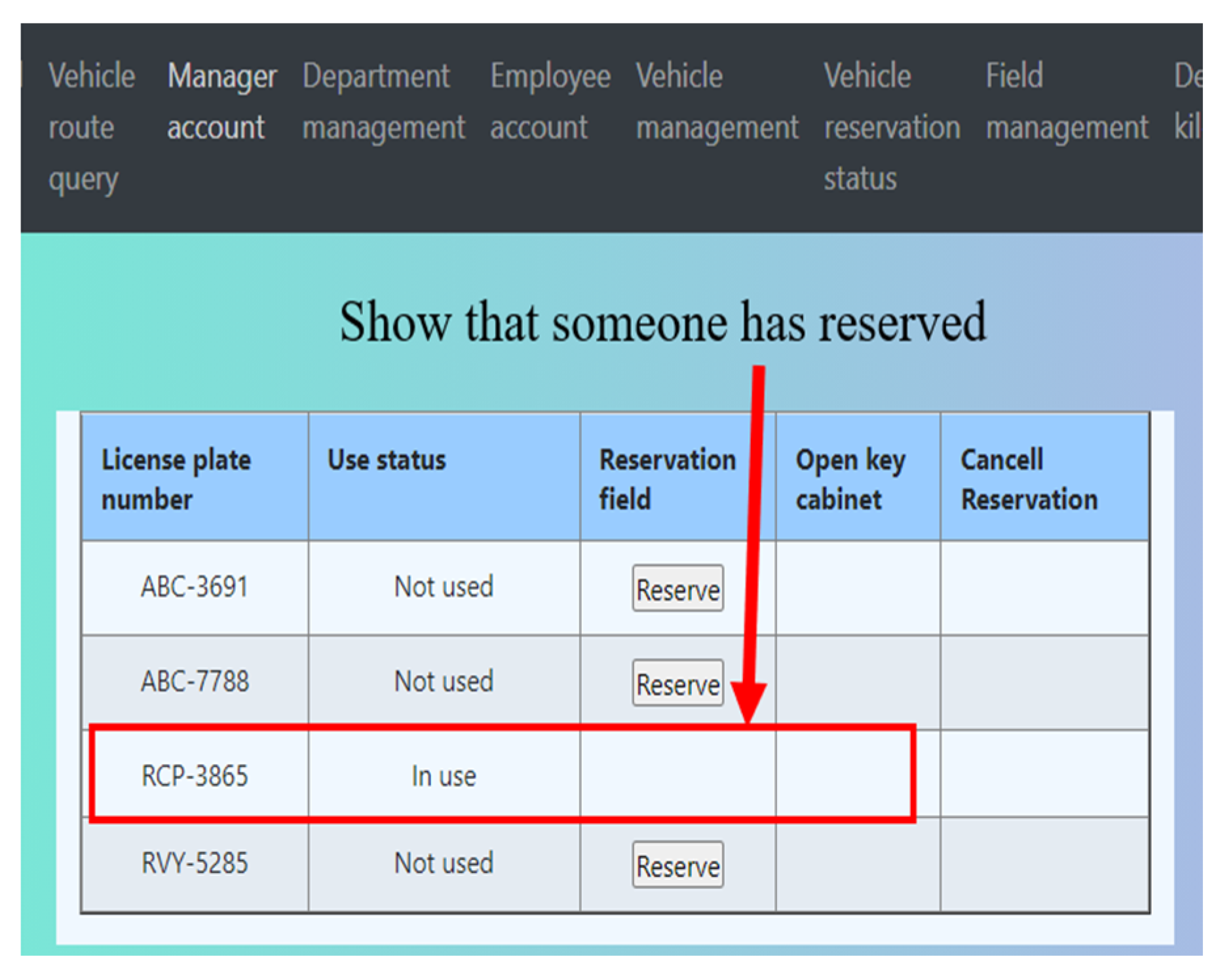
- Manager account for uses including information of people, groups, and administrator accounts;
- (d)
- Group management for users by teams or departments;
- (e)
- Employee’s account for the mobile phone number, name, and employee number;
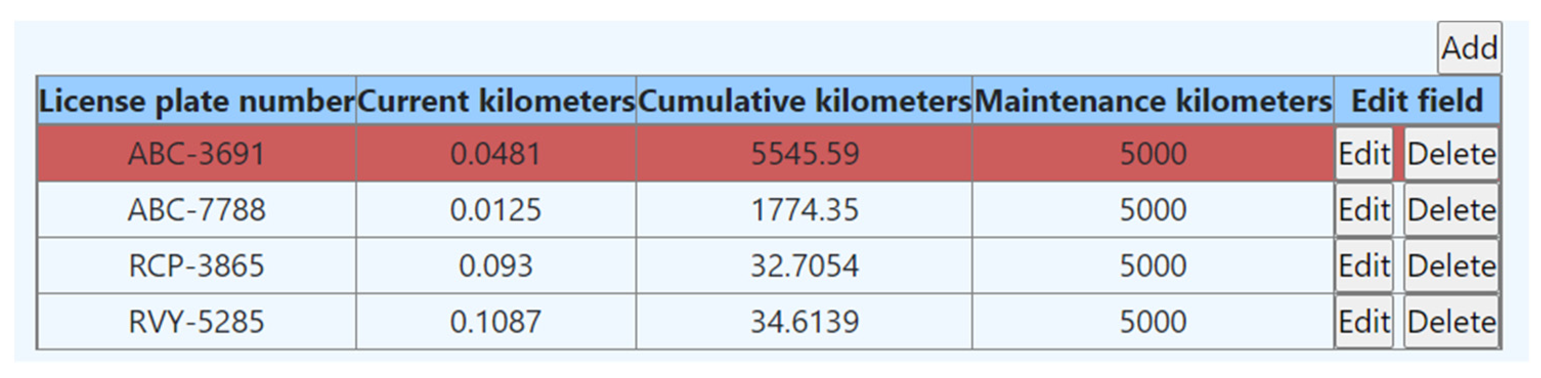
- (f)
- Vehicle management for recording total and recent mileage of a vehicle and warning for vehicle maintenance;
- (g)
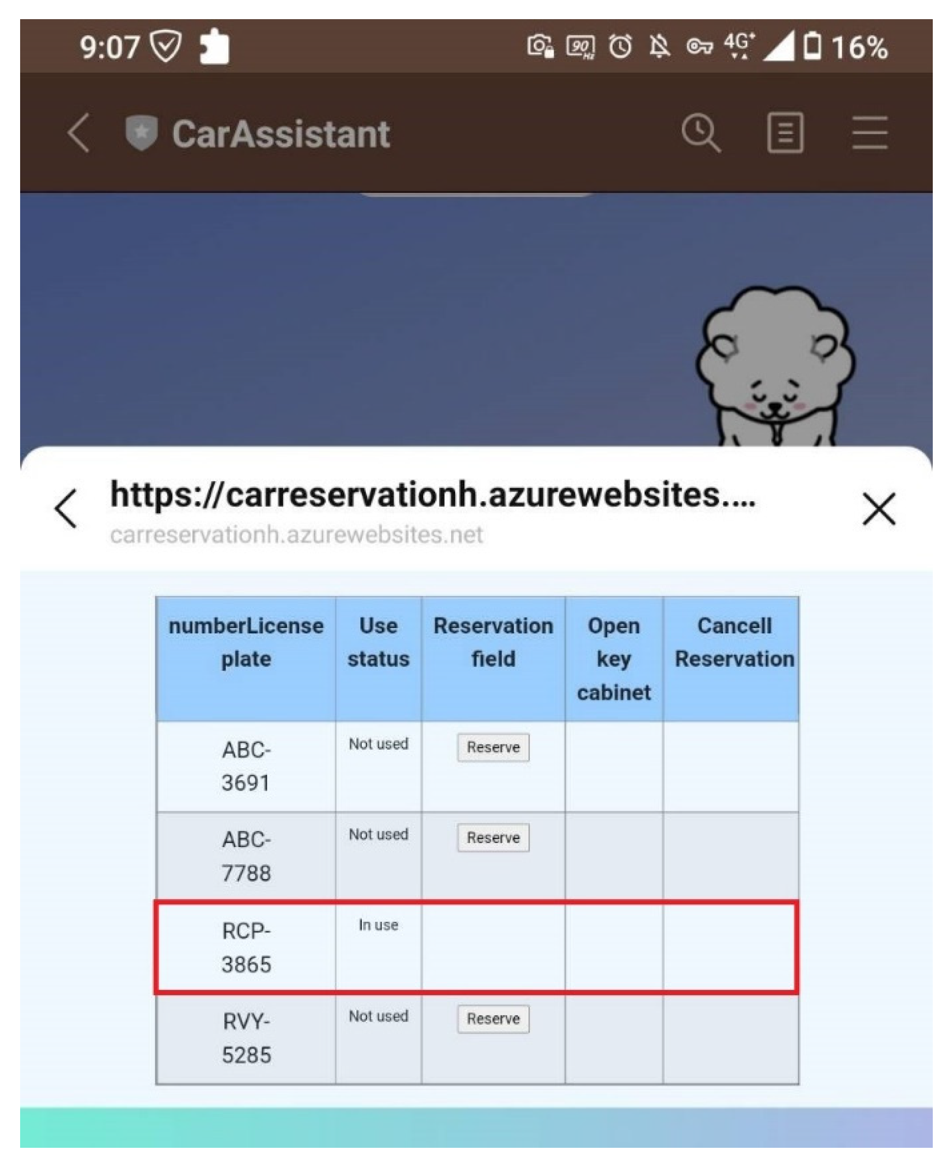
- Vehicle reservation for showing the status of vehicles;
- (h)
- Field management for checking the status of keys and STBs;
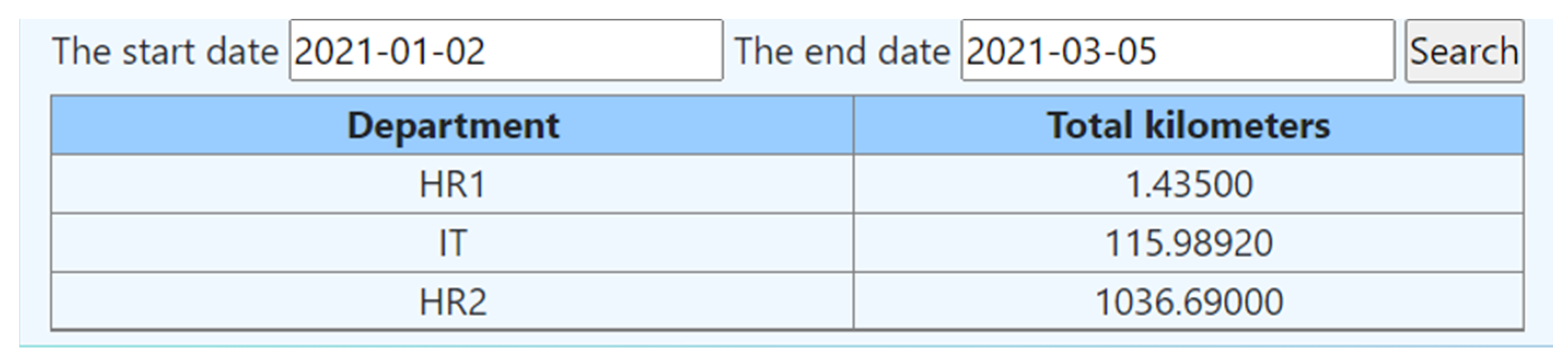
- (i)
- Mileage check by vehicles, groups (departments) in a certain period.
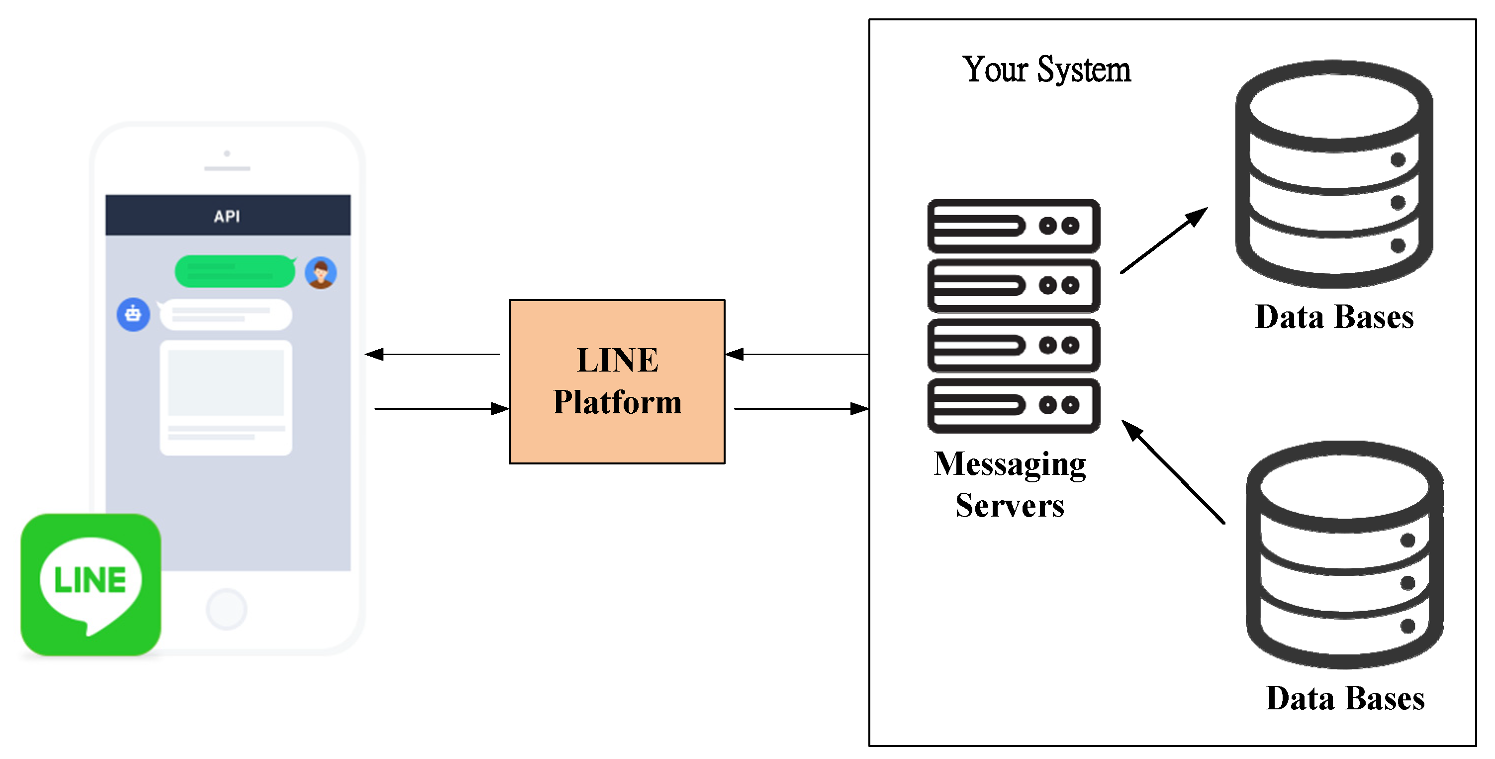
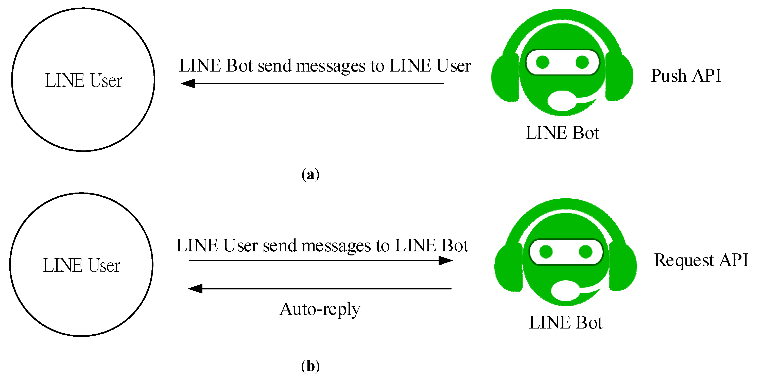
2.4. LINE Bot
3. System Build-Up and Test Results
3.1. STB
3.2. Key Cabinet
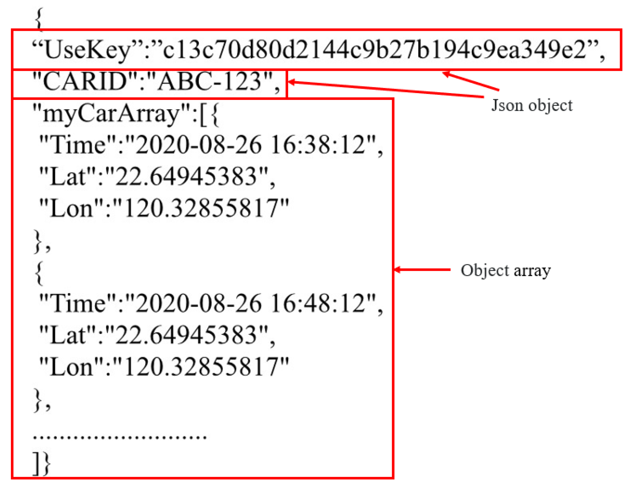
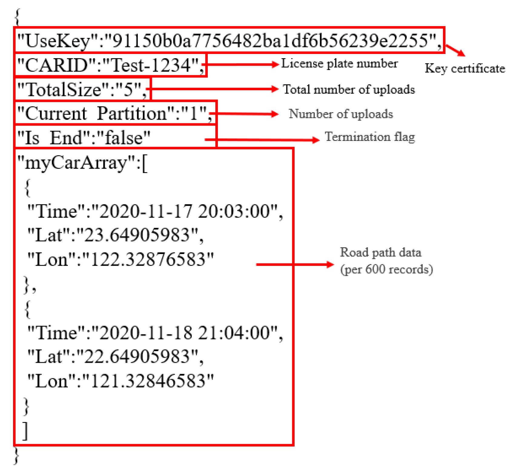
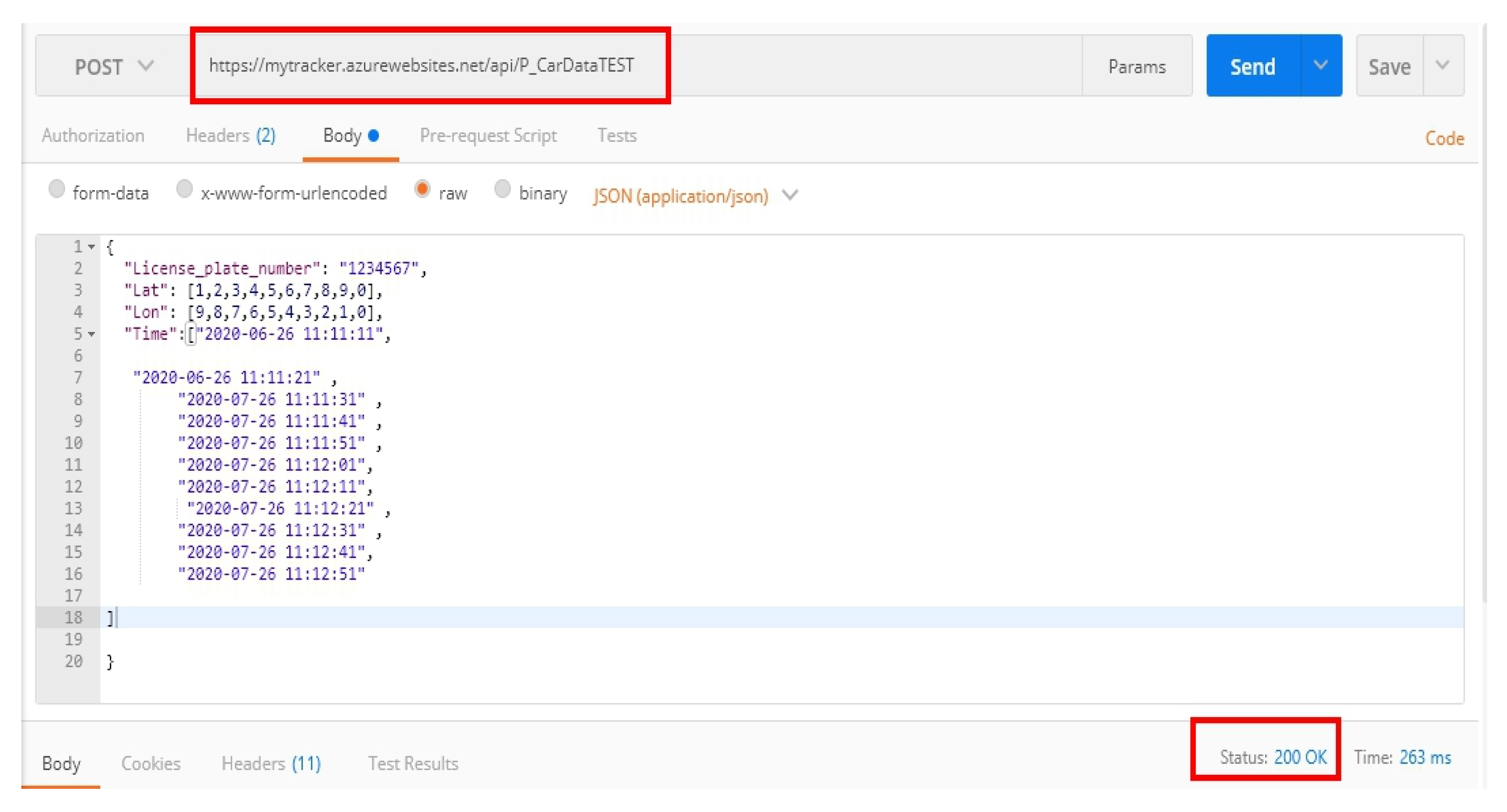
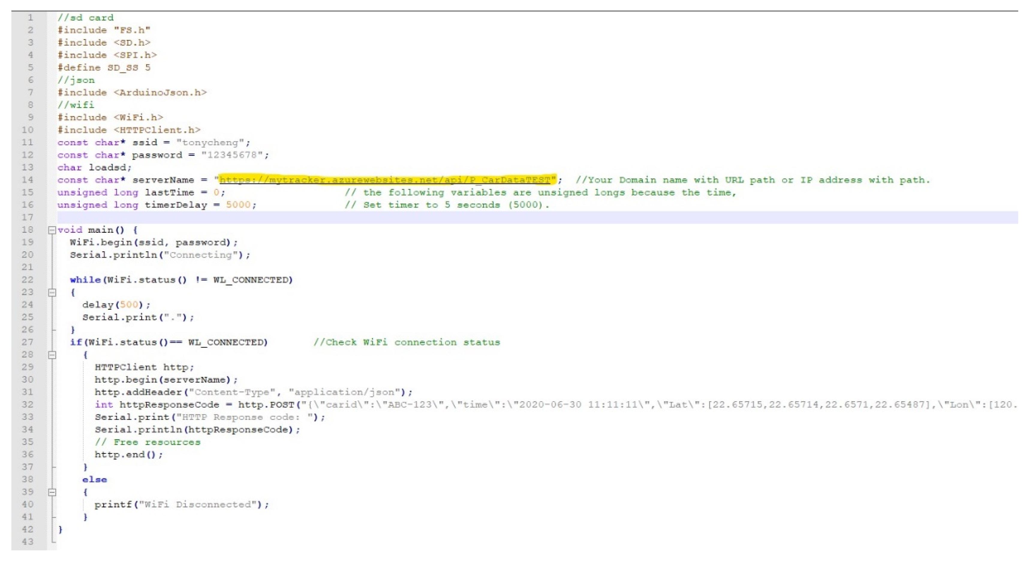
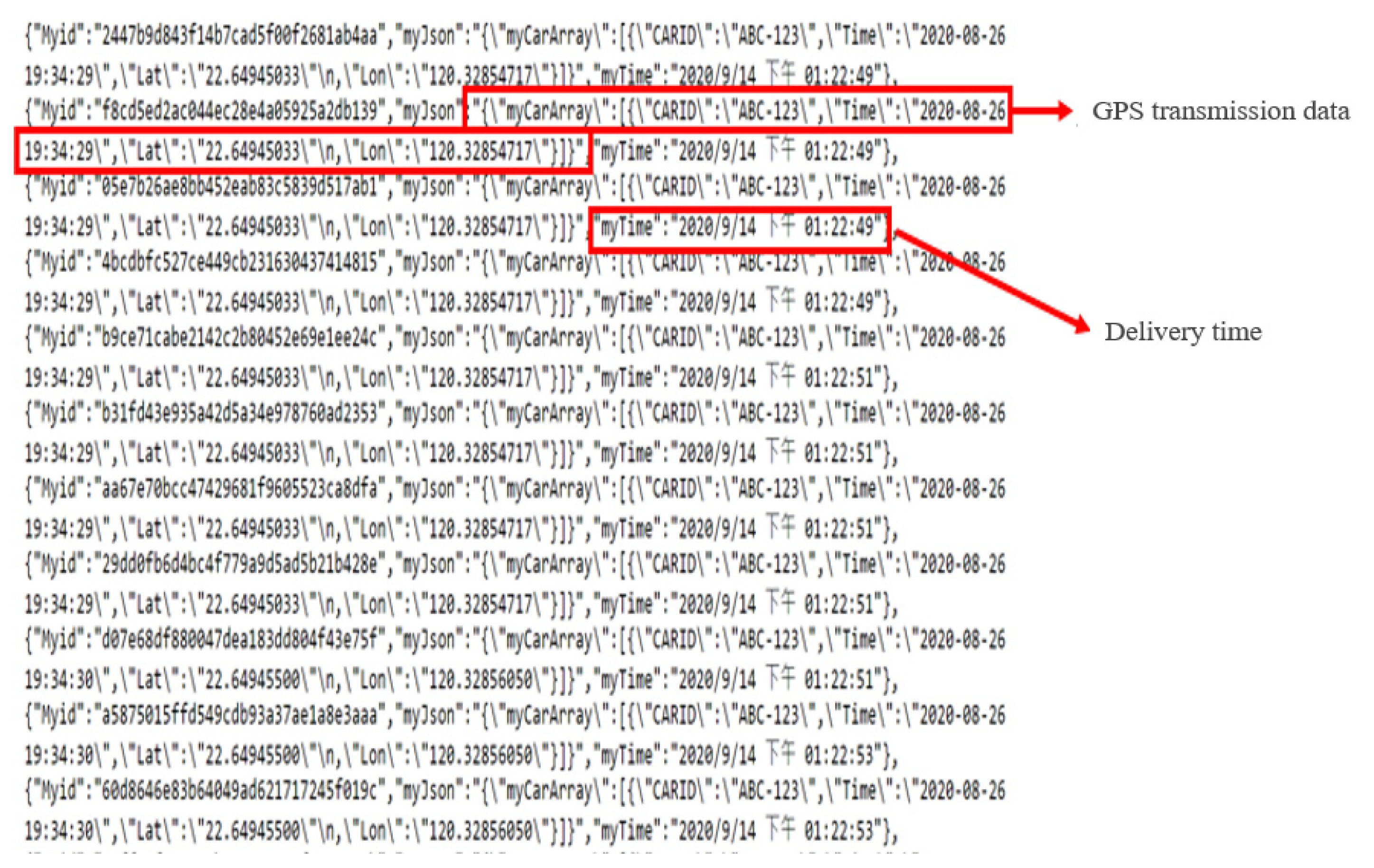
3.3. Data Format Transmission Test
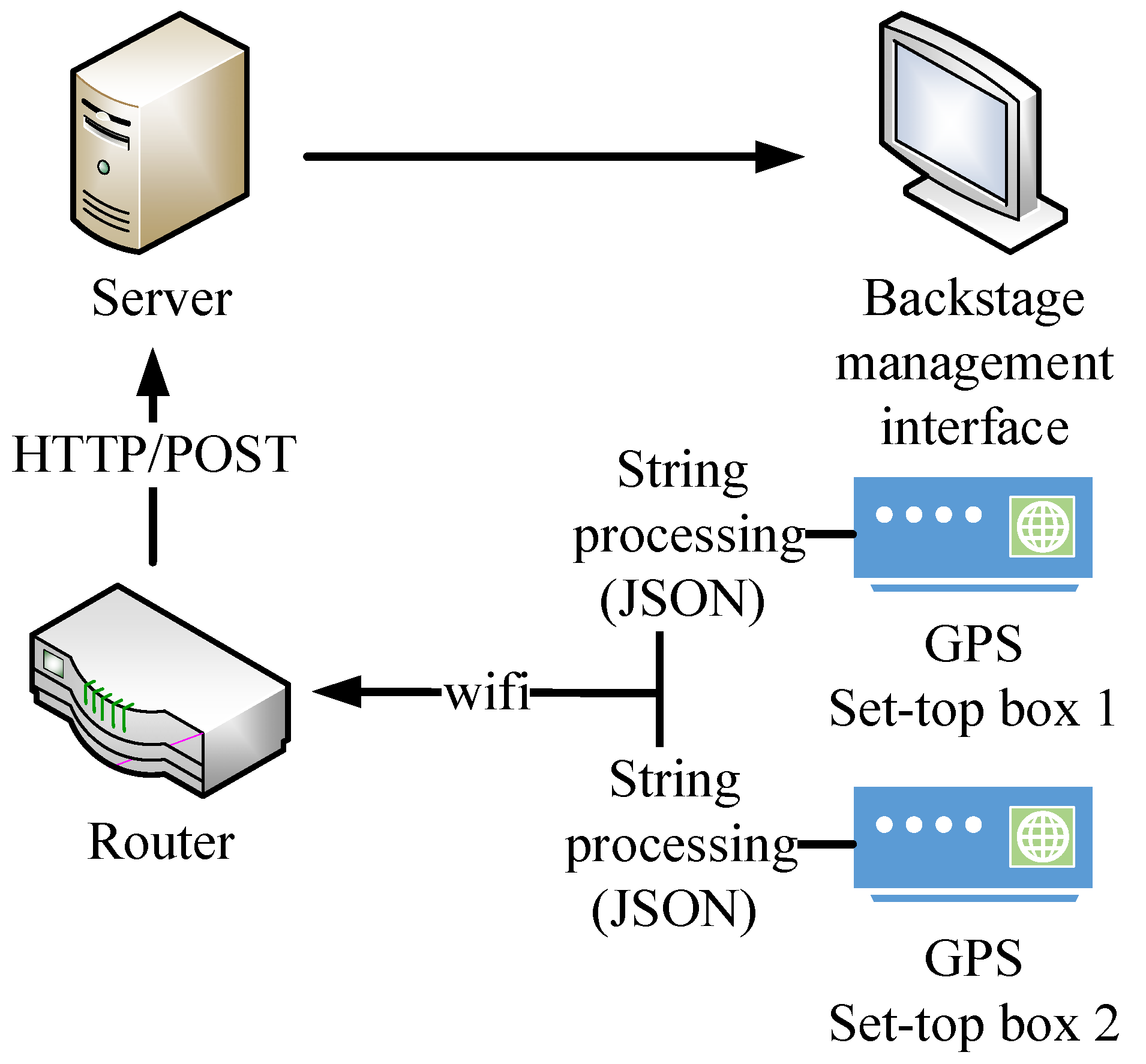
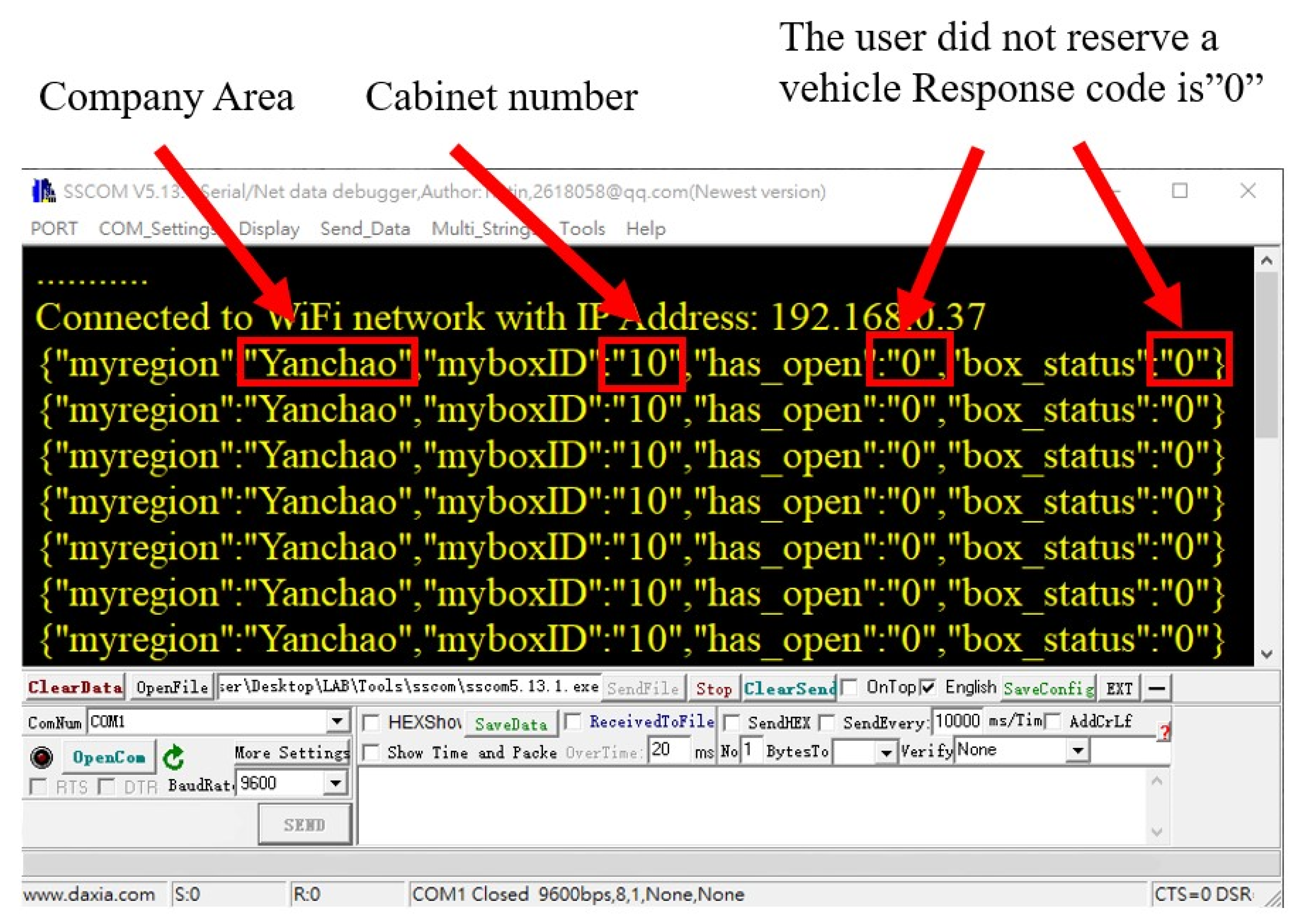
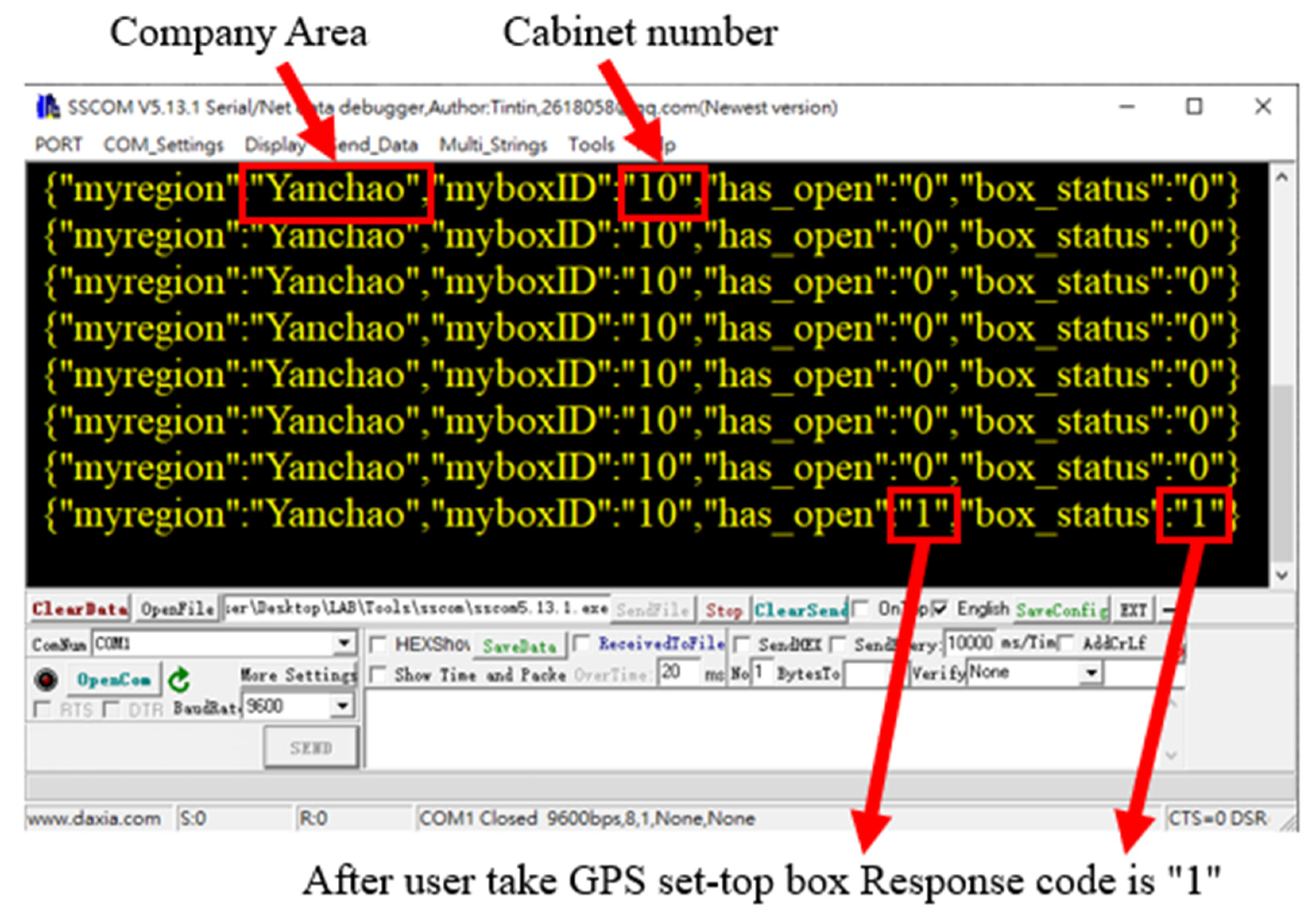
3.4. Communication Transmission Test
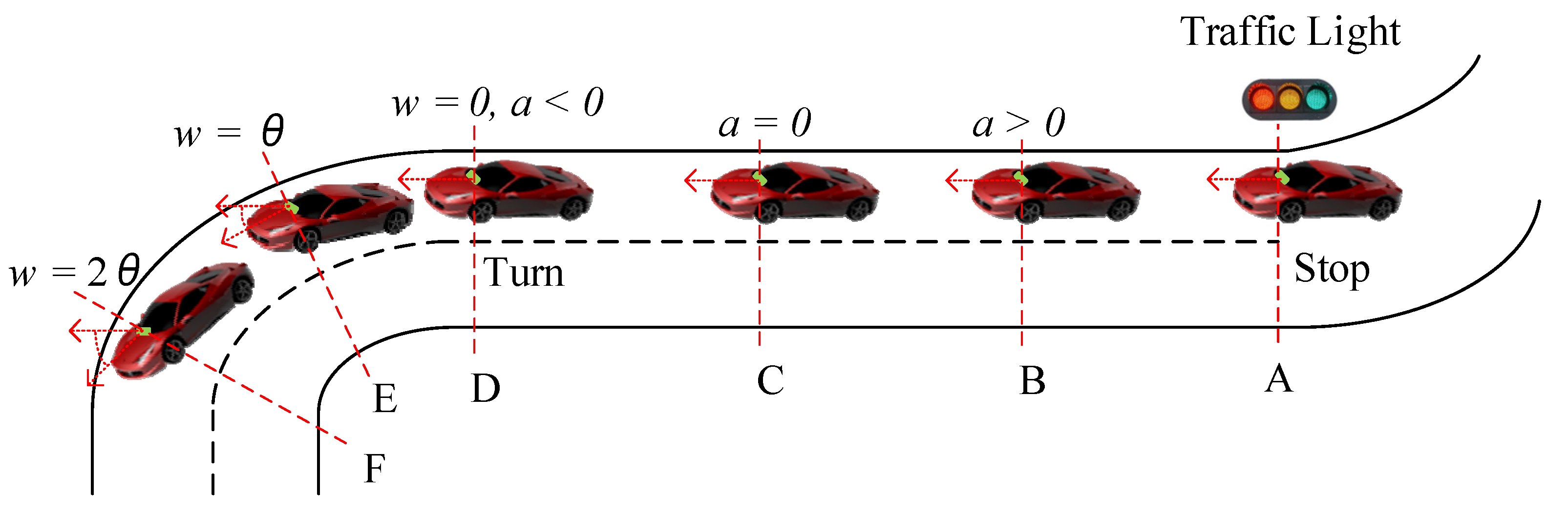
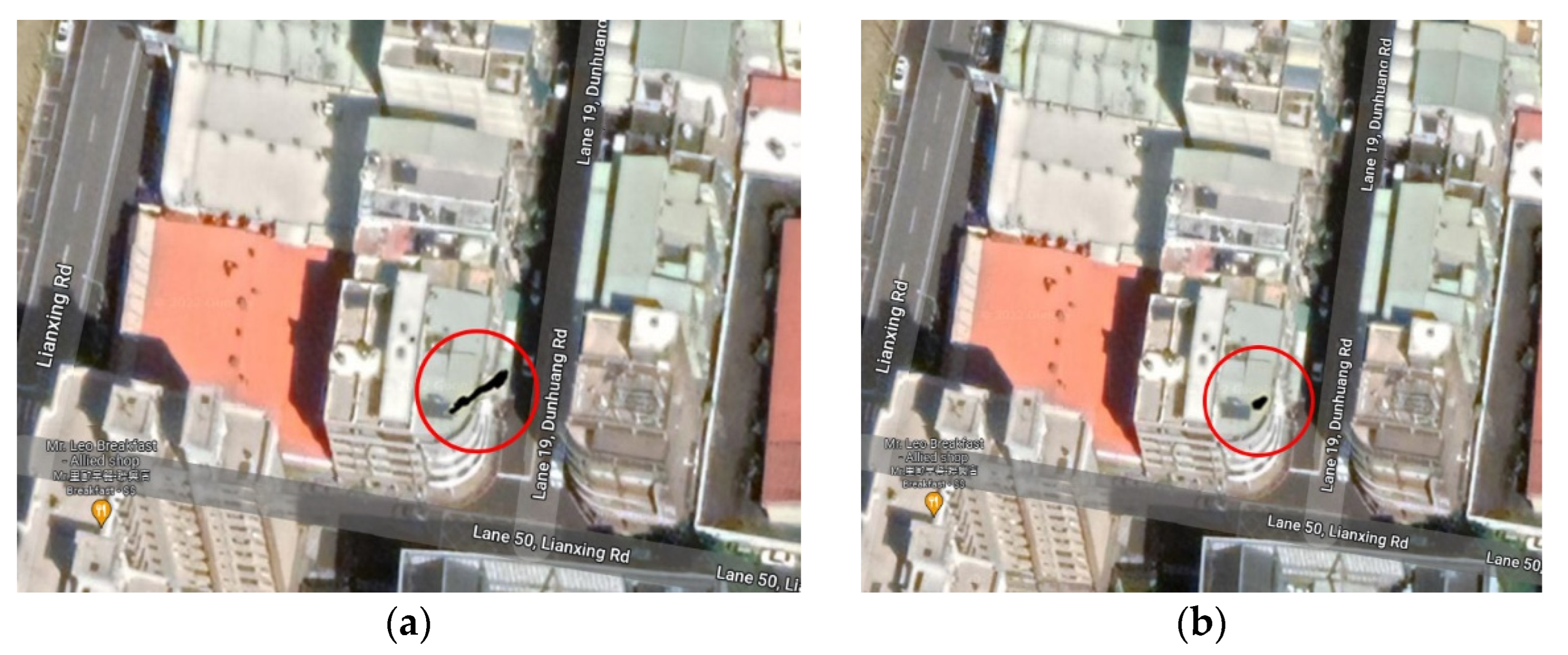
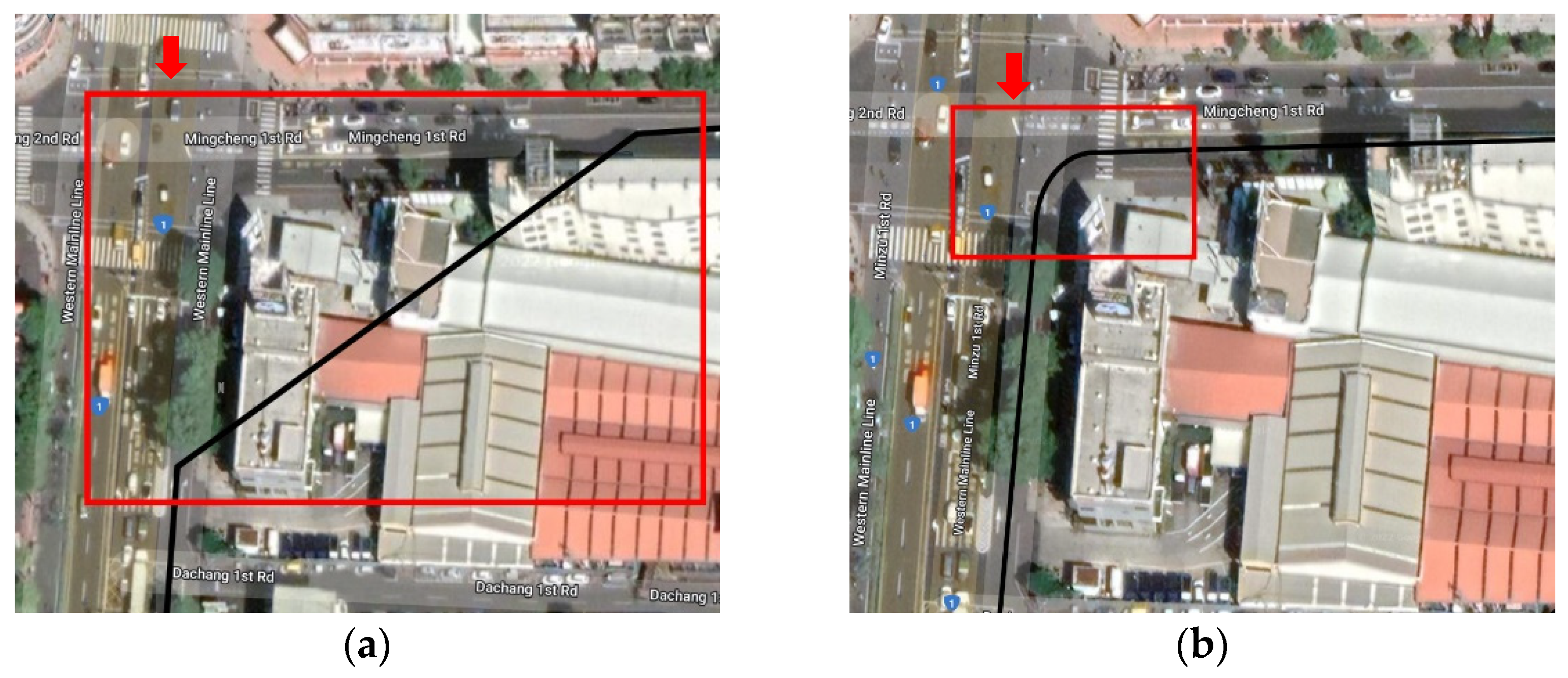
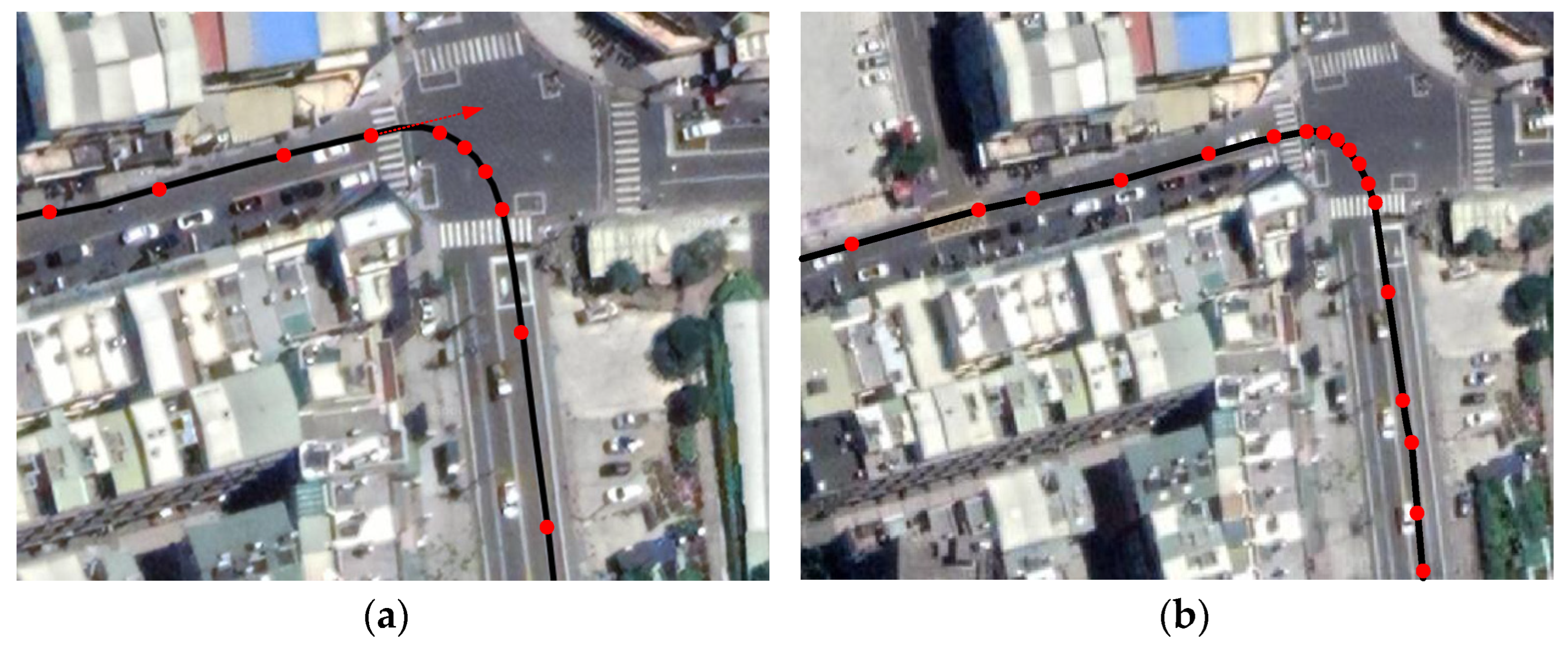
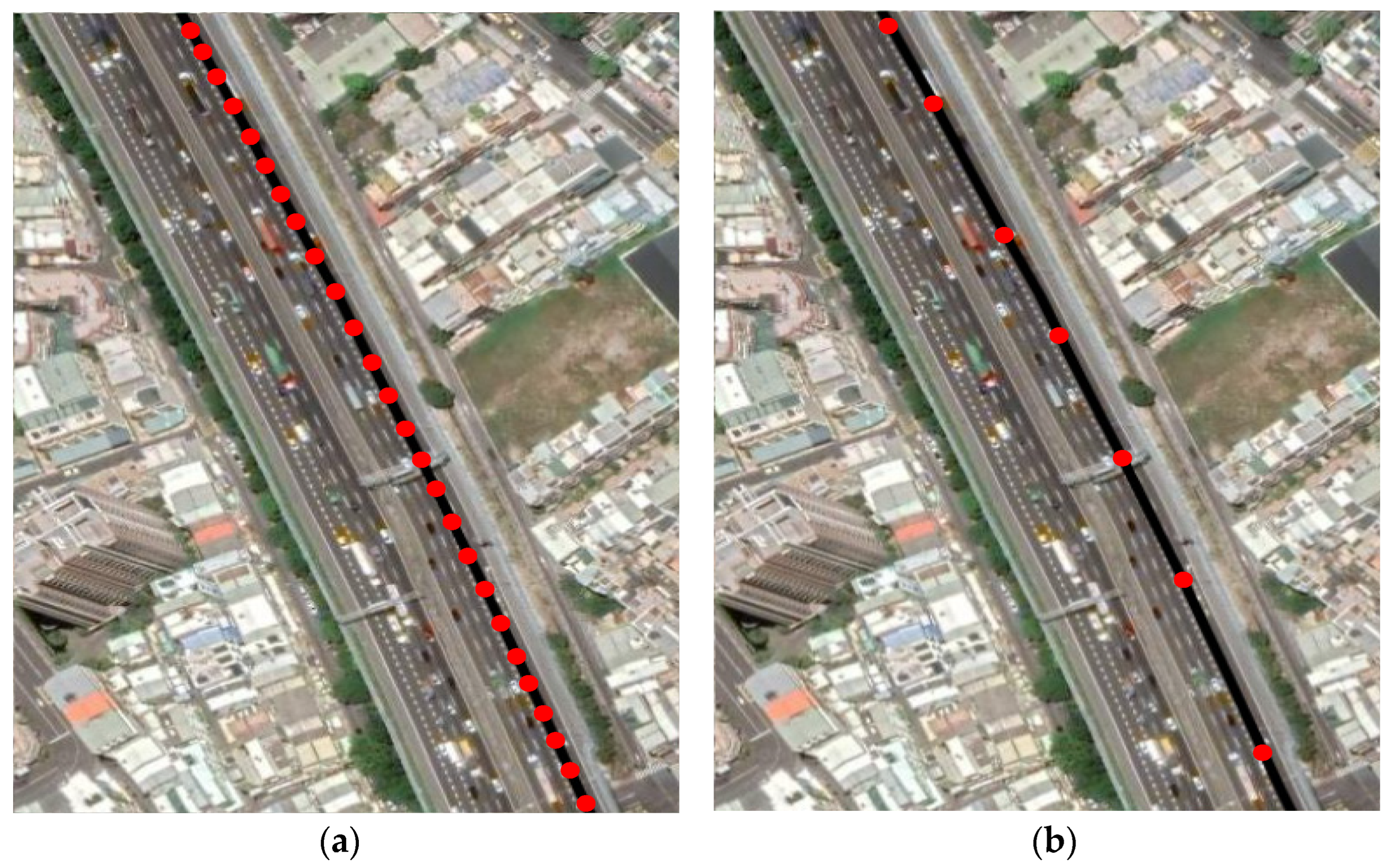
3.5. Actual Measurement of Driving
3.6. Back-End Management System
4. Conclusions
Author Contributions
Funding
Institutional Review Board Statement
Informed Consent Statement
Data Availability Statement
Acknowledgments
Conflicts of Interest
References
- Almomani, I.M.; Alkhalil, N.Y.; Ahmad, E.M.; Jodeh, R.M. Ubiquitous GPS vehicle tracking and management system. In Proceedings of the 2011 IEEE Jordan Conference on Applied Electrical Engineering and Computing Technologies (AEECT), Amman, Jordan, 6–8 December 2011; pp. 1–6. [Google Scholar]
- Ramadan, M.N.; Al-Khedher, M.A.; Al-Kheder, S.A. Intelligent Anti-Theft and Tracking System for Automobiles. Int. J. Mach. Learn. Comput. 2012, 2, 83–88. [Google Scholar] [CrossRef]
- Fleischer, P.B.; Nelson, A.Y.; Sowah, R.A.; Bremang, A. Design and development of GPS/GSM based vehicle tracking and alert system for commercial inter-city buses. In Proceedings of the 2012 IEEE 4th International Conference on Adaptive Science & Technology (ICAST), Kumasi, Ghana, 25–27 October 2012; pp. 1–6. [Google Scholar]
- Behzad, M.; Sana, A.; Khan, M.A.; Walayat, Z.; Qasim, U.; Khan, Z.A.; Javaid, N. Design and Development of a Low Cost Ubiquitous Tracking System. Procedia Comput. Sci. 2014, 34, 220–227. [Google Scholar] [CrossRef] [Green Version]
- Joshi, N.; Tripathy, A.K.; Sawant, S.; Patel, T.; Waghmare, S.; Clusher, B. Near real time vehicle tracking using GIS. In Proceedings of the 2015 International Conference on Technologies for Sustainable Development (ICTSD), Mumbai, India, 4–6 February 2015; pp. 1–6. [Google Scholar]
- Zhang, R.; Liu, W.; Jia, Y.; Jiang, G.; Xing, J.; Jiang, H.; Liu, J. WiFi Sensing-Based Real-Time Bus Tracking and Arrival Time Prediction in Urban Environments. IEEE Sens. J. 2018, 18, 4746–4760. [Google Scholar] [CrossRef]
- Dewan, M.; Agarwal, A. IOT Based Smart Vehical Monitoring and Tracking System. In Proceedings of the 2020 9th International Conference System Modeling and Advancement in Research Trends (SMART), Moradabad, India, 4–5 December 2020; pp. 175–178. [Google Scholar]
- Hussain, S.; Mahmud, U.; Yang, S. Car e-Talk: An IoT-Enabled Cloud-Assisted Smart Fleet Maintenance System. IEEE Internet Things J. 2021, 8, 9484–9494. [Google Scholar] [CrossRef]
- Ab Majid, R.; Mohamed, N.; Haron, R.; Omar, N.B.; Jomitin, B. Misappropriation of Assets in Local Authorities: A Challenge to Good Governance. Procedia Soc. Behav. Sci. 2014, 164, 345–350. [Google Scholar] [CrossRef] [Green Version]
- Boonsong, W. Smart Intruder Notifying System Using NETPIE through Line Bot Based on Internet of Things Platform. In Proceedings of the 2019 IEEE 5th International Conference on Computer and Communications (ICCC), Chengdu, China, 6–9 December 2019. [Google Scholar]
- Chen, Y.H.; Huang, N.F.; Tzeng, J.W.; Lee, C.A.; Huang, Y.X.; Huang, H.H. A Personalized Learning Path Recommender System with Line Bot in MOOCs Based on LSTM. In Proceedings of the 2022 11th International Conference on Educational and Information Technology (ICEIT), Chengdu, China, 6–8 January 2022. [Google Scholar]
- Oraizi, H.; Soleimani, H. Optimum pattern synthesis of non-uniform spherical arrays using the Euler rotation. IET Microw. Antennas Propag. 2015, 9, 898–904. [Google Scholar] [CrossRef]
- Sheu, B.H.; Chiu, C.C.; Lu, W.T.; Huang, C.I.; Chen, W.P. Development of UAV Tracing and Coordinate Detection Method Using a Dual-Axis Rotary Platform for an Anti-UAV System. Appl. Sci. 2019, 9, 2583. [Google Scholar] [CrossRef] [Green Version]


| Messages | Meaning |
|---|---|
| GGA | Time (UTC), Latitude, N or S (North or South), Longitude, E or W (East or West), GPS Quality Indicator, Number of satellites in view, Horizontal Dilution of precision, Antenna Altitude above/below mean-sea-level, Units of antenna altitude, etc. |
| GLL | Latitude, N or S (North or South), Longitude, E or W (East or West), Time (UTC), Status A-Data Valid, V - Data Invalid, Checksum. |
| GSA | Selection mode, PDOP, HDOP, VDOP, the ID of 1st satellite used for the fix, etc. |
| GSV | A total number of messages, Message number, satellite in view, Satellite number, Elevation in degrees, Azimuth in degrees to true, SNR, Checksum. |
| RMA | Latitude, N or S, Longitude, E or W, Time Difference, Magnetic Variation, Speed Over Ground, etc. |
| RMC | Time (UTC), Status, Latitude, N or S, Longitude, E or W, Speed over ground, Track degrees, Date, Magnetic Variation, Checksum. |
| VTG | Track Degrees, Speed Knots, Speed Kilometers Per Hour, Checksum, etc. |
| Response Code | Status | GPS STB Action |
|---|---|---|
| 0 | Data upload error | Specific data retransmission |
| 1 | Data reconstruction fail | All data retransmission |
| 2 | Success | Lighting-off/Sleep-mode |
| 3 | Unknown error | The buzzer keeps beeping |
Publisher’s Note: MDPI stays neutral with regard to jurisdictional claims in published maps and institutional affiliations. |
© 2022 by the authors. Licensee MDPI, Basel, Switzerland. This article is an open access article distributed under the terms and conditions of the Creative Commons Attribution (CC BY) license (https://creativecommons.org/licenses/by/4.0/).
Share and Cite
Hsu, K.-T.; Lu, W.-C.; Jheng, H.-Y.; Hung, Y.-T.; Chen, X.-Z.; Chen, W.-P. Integrated System for Official Vehicles with Online Reservation and Moving Path Monitoring. Appl. Sci. 2022, 12, 4777. https://0-doi-org.brum.beds.ac.uk/10.3390/app12094777
Hsu K-T, Lu W-C, Jheng H-Y, Hung Y-T, Chen X-Z, Chen W-P. Integrated System for Official Vehicles with Online Reservation and Moving Path Monitoring. Applied Sciences. 2022; 12(9):4777. https://0-doi-org.brum.beds.ac.uk/10.3390/app12094777
Chicago/Turabian StyleHsu, Kuo-Tai, Wei-Chang Lu, Hao-Yu Jheng, Yun-Ting Hung, Xin-Zhang Chen, and Wen-Ping Chen. 2022. "Integrated System for Official Vehicles with Online Reservation and Moving Path Monitoring" Applied Sciences 12, no. 9: 4777. https://0-doi-org.brum.beds.ac.uk/10.3390/app12094777