1. Introduction
Drones are essential components of the Unmanned Aerial System (UAS) [
1]. During the past decade, drones have been deployed for various real-life applications such as inspections [
2,
3,
4,
5,
6], surveillance and reconnaissance [
7,
8], package delivery [
9,
10], search and rescue [
8], agriculture [
8,
11], remote sensing [
8], transportation [
12], emergency medical services [
13,
14], and military operations [
1,
8,
15]. Drones with sensing capabilities make them highly applicable for inspections in critical environments that are not easily accessible to humans. In such settings, drones bring significant benefits including reduced operational cost, time, and risk for inspectors, as well as improved inspection quality.
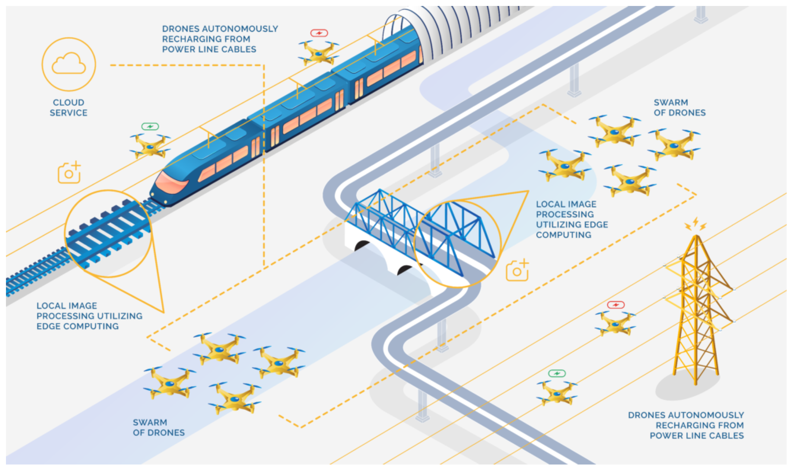
The European research and innovation project Drones4Safety (D4S) strives to increase the safety of the European civil transport system by building a cooperative, autonomous, and continuously operating drone system that will be offered to railway and bridge inspection operators to inspect their transportation infrastructure accurately, frequently, and autonomously [
16]. A swarm of drones addresses this ambitious objective by providing safe and cost-efficient inspection missions (
Figure 1).
To circumvent the limited flight time, drones will be integrated with the capability to navigate to and detect nearby powerline cables for recharging [
17].
Our use cases utilize high-resolution cameras with onboard fault detection algorithms to identify damages and deterioration of structural parts of bridges and the catenary system of railways. We use digital 3D reconstructions of targeted bridges or railway segments from pre-flight activities for mission planning [
18]. The swarm of drones is connected with cloud services such that the ground segment, supporting the autonomous mission, is updated with the latest information concerning flight restrictions over the target assets. Furthermore, cloud services publish a coarse motion path for the swarm by disseminating waypoints defining a route from the launch location to the end location of the inspection.
Our key contributions constitute the design of a custom-built drone swarm based on open hardware and software components integrating algorithms for obstacle avoidance, cable detection and identification, motion path planning, formation flying, and fault detection. We validate the integration of system components in a UAS operation by linking the drone system to ground infrastructure and supporting cloud services. Our innovative UAS combines the advantages of autonomous drones with algorithms for fault detection, navigation, and swarming supported by cloud computing services.
The paper is organized as follows:
Section 2 discusses work related to infrastructure inspections with drone swarms. In
Section 3, we model the concept of operation for the cooperative drone swarm.
Section 4 and
Section 5 introduce the drone hardware and the supporting cloud services, respectively. Communication aspects are described in
Section 6. In
Section 7, we introduce key algorithms and protocols to support autonomous inspections with a drone swarm.
Section 8 gives selected examples of the validation of the system design, and
Section 9 concludes the paper.
2. Related Work
Infrastructure inspections have traditionally been performed as ground-based visual inspections. This method is laborious and suffers from low coverage of difficult-to-access areas. The main added value of inspections with drones is their ability to cover inspection targets efficiently and accurately often in areas inaccessible by foot or manned vehicles. To reduce the cost of labor, a variety of autonomous platforms have been introduced in the literature. These platforms cover unmanned ground vehicles, fixed-wing drones [
19], rotor-based drones [
2], autonomous robotic blimps [
20], and even hybrid [
6] or cooperative solutions [
21].
Table 1 compares different unmanned platforms for infrastructure inspections.
Despite the low operational risk of inspections with ground-based vehicles, we focus on autonomous Unmanned Aerial Vehicle (UAVs) in our study. Our proposed UAS design is based on the multi-rotor drone platform as it offers a good trade-off between inspection quality, maneuverability, flexibility, and cost-efficiency. The multi-rotor drone can pass over terrain that may be impossible to cross for ground vehicles and ground personnel, hovering at specific locations and acquiring high-resolution inspection images. For long-duration inspection, a recharging scheme or a drone replacement scheme is needed [
22]. However, this topic is beyond the scope of this paper.
The concept of using cooperative drones as part of a UAS has been discussed in the literature [
23,
24]. In a countermeasure UAS, drones can identify and neutralize multiples malicious drones through cooperation [
23]. The authors of [
23] review the available technologies for sensing, mitigation, and command and control systems. Another recent review of the state-of-the-art of swarm-based UASs provided a set of recommendations on the specific types, modes of communication, architectures, and swarm patterns for particular applications of a swarm-based UAS [
24]. Common to these studies is the lack of motivation for specific and chosen technologies to instantiate the UAS. However, while several studies in the literature point to specific technologies for UAS design, there is a gap in knowledge concerning design aspects when taking into account the UAS as a whole.
Several papers address the application of drones for bridges [
2,
25] and railway inspections [
26,
27]. Seo et al. [
25] studied details of drone-enabled inspections and presented considerations to obtain optimum data acquisition. The authors recommended a five-stage bridge inspection methodology using a commercial drone. The method involves a bridge information review and site risk assessment analyzing information about the inspection target and the surrounding area. A drone pre-flight setup is used to conduct a thorough inspection of the drone before the first flight. The following drone-enabled inspection and the damage identification stages define the core objectives of the inspections. Jing et al. [
26] gave an overview of sensors and platforms for railway inspections and highlighted several benefits of using UAVs for these inspections [
26]. Recommendations from the survey pointed toward the need for lightweight sensor development and robustness in the design of Artificial Intelligence (AI) components. Another important aspect was the needed collaboration between railway companies and the robot manufacturer to ensure a successful system design. Flammini et al. [
27] discussed the emerging applications of drones in the railway domain. The authors point out that drone-based monitoring can be advantageously integrated into existing security surveillance systems for railway infrastructures.
To accomplish inspection missions efficiently, drone swarms need to communicate with each other and coordinate the allocation of tasks. By using multiple drones with coordination and cooperation capabilities, drones can inspect different parts of the infrastructure simultaneously, thus saving time on the inspection [
28,
29]. Today, drones are typically applied as piloted single-drone systems without internet connectivity and access to cloud services. Therefore, the swarm operation is limited to centralized coordination with no inter-drone coordination.
Comparing our study to related studies in the literature, we find that our proposed UAS aligns well with widely accepted concepts. To complement existing reports, we propose a system design and advance the existing knowledge base by providing specific technology choices with proof-of-concept design and validation of swarm-based UASs. Our literature survey did not reveal papers that discuss UAS design holistically as in our study. A holistic approach to UAS system design is important to circumvent unnecessary sub-optimization and to provide better system performance as a whole taking into account the concept of operation, the design of individual components (e.g., hardware and software), and their interplay.
3. Concept of Operation
An inspection mission is defined as a data structure that describes the objective and the associated data concerning the mission type, the starting and ending locations, a geofence of the inspection, camera settings, etc. A mission is divided into a set of tasks e.g., recording images at defined locations relative to the inspection target. Tasks are allocated to drones of the swarm in the operation. The swarm of autonomous drones carries out the inspection mission by executing the tasks of the mission until all tasks have been completed. First, drones navigate to the starting location of the mission guided by a global path plan. A task allocation protocol decides the allocation of individual mission tasks to drones. The drone swarm continuously executes new tasks when a previously assigned task has been completed. An inspection mission is constrained by the available energy (battery charge) of the drones. Each drone will need to go through several charging cycles during an inspection mission. Drones report telemetry data such as location, velocity, currently assigned task, and charging level to a Ground Control Station (GCS), which continuously monitors the progress of an inspection mission. They connect to the mission control in the cloud to upload data (e.g., images and classified faults) from the inspection. When all tasks of the mission are completed, the drone swarm is retrieved from the inspection area.
Figure 2a shows an activity diagram describing the inspection initiation process. When drones are turned on, they connect to GCS. Communication in a wireless mesh formation ensures the foundation for cooperative functions. A mission is assigned to the drone swarm by retrieval of the mission specification from the cloud services. A validation step ensures that initial settings are in place and that the drone swarm is ready to begin the inspection mission.
Figure 2b shows an activity diagram for a task inspection for a single drone of the swarm. The process presumes that the mission has been initialized. A task allocation protocol provides a set of prioritized inspection tasks. Individual drones perform tasks following their allocations and priority. Subsequently, a cooperative path planning process is completed that ensures that drones can fly together as a swarm along the same route without colliding [
30]. A specification of the formation constraints is used as an input in the cooperative path planning. Part of the cooperative path planning embeds a waypoint-guided path planning that describes the inspection path a drone should undertake to position itself in the right viewpoints for taking inspection images. The telemetry reporting activity ensures that the progress and telemetry reports are sent to the GCS. The progress monitoring supervises the progress of the prioritized list of inspection tasks. When a task has been completed, it breaks out of the loop and proceeds to the end node through the join node. The energy monitoring provides the charge status of the drone and is continuously monitored. If the charge falls below a defined threshold, the drone breaks out of the loop and proceeds with a charging protocol. Finally, the inspection flying activity is responsible for the drone visiting the waypoints defined in the cooperative path plan and acquiring inspection images according to the specification provided in the task specification. The acquired images are transferred to a storage system from where they can be fetched and sent to the cloud services asynchronously.
4. Drone Design
Our drone hardware platform is a custom-built design based on building blocks used by several others in drone research. The primary considerations cover the flight-critical hardware and software, the application processing platform, and the auxiliary sensors and these differentiating elements for our inspection application.
4.1. Drone Hardware and Software
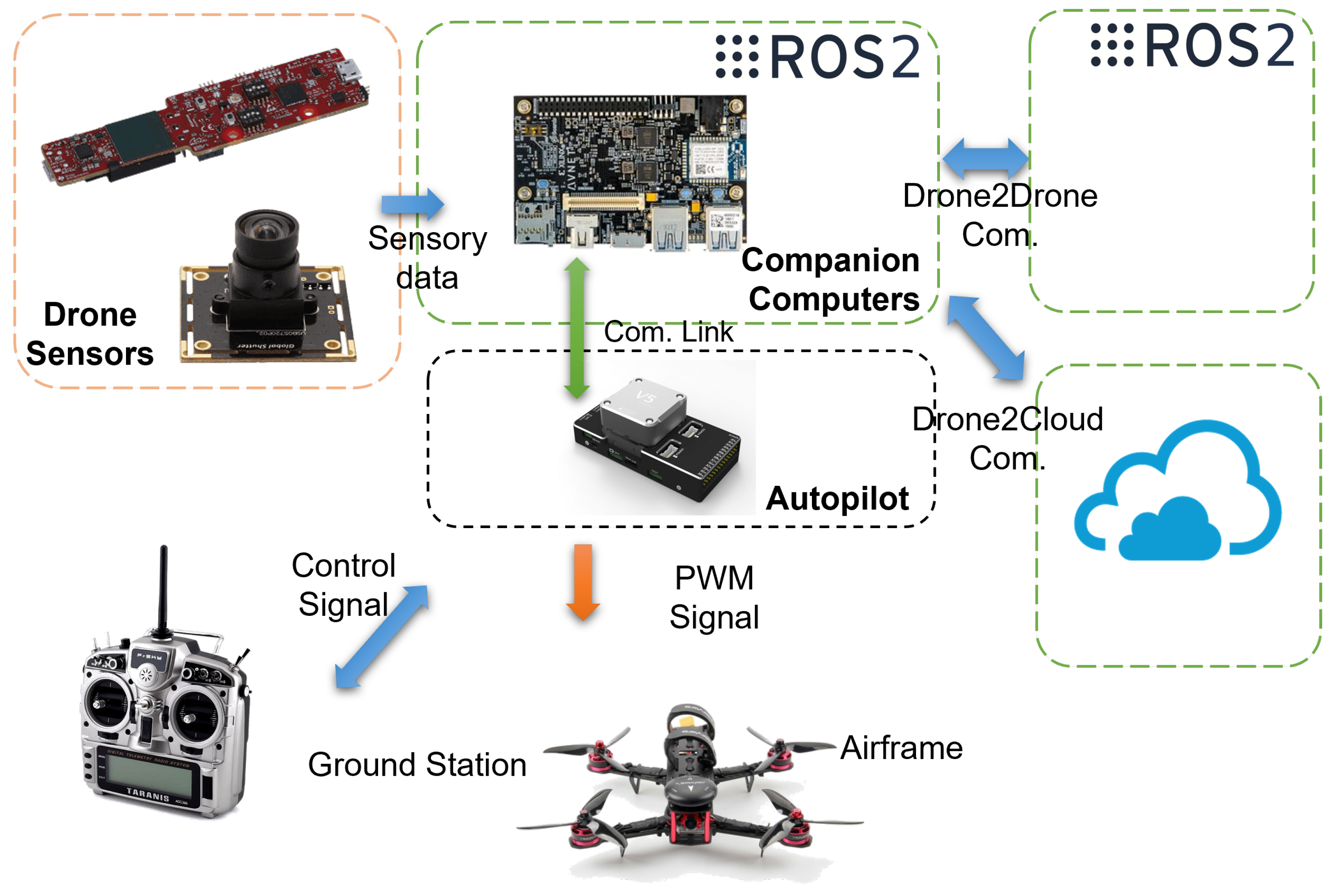
The drone hardware is shown in
Figure 3 and comprises a quadrotor airframe and standard drone components such as a battery, brushless DC motors, propellers, Electronic Speed Controller (ESCs), etc. Various versions were used throughout the design and testing, allowing for a generic hardware configuration depending on payload requirements. The computational system is small, lightweight, and flexible enough to fit almost any drone. Therefore, considerations about the drone airframe and mechanical design do not depend on the computational hardware but instead focus mainly on meeting requirements for parameters such as payload capacity and wind resistance.
Low- and high-level processing happens on computational electronics. The computations necessary for drone operations are generally divided into two categories: flight-critical processing and application processing. Following this distinction, computational electronics covers two separate computational boards.
The flight controller is responsible for flight-critical processing. This includes redundant processing for flight control and stability, Inertial Measurement Unit (IMU) and Global Positioning System (GPS) interfacing, and safety features. The CUAVv5+ flight controller running the feature-rich PX4 flight software stack is used. The companion computer is responsible for all application processing for the drone. On this board, all non-flight critical systems are running, including detection processing, swarming applications, inspection applications, etc. The companion computer fetches internal information from the flight controller while providing the flight controller with high-level control inputs to achieve the mission. As a companion computer, Avnet, the Ultra96v2 board is used (
Figure 4a), featuring an MPSoC composed of a CPU as well as a Field-Programmable Gate Array (FPGA) for adaptive computing, which is the newest branch of computational paradigm for mobile robotics with limited resources required to run advanced and heavy algorithms.
The firmware and Operating System (OS) are built specifically to enable the required software to run on the onboard computer. The firmware includes Linux drivers, hardware device tree specifications, and kernel modules built specifically for the Ultra96v2 board using a Yocto-based Linux distribution designed with the Xilinx tools Petalinux and Vivado. Using the own-developed tool MPSoC4Drones [
32], the low-level firmware is combined with an Ubuntu operating system for maximum compatibility with existing robotics software. On top of the Ubuntu OS, Robot Operating System version 2 (ROS2) is running and communicating with the flight controller using FastRTPS. Additionally, FPGA implementations can be appended to the software stack for the acceleration of heavy computational components.
4.2. Sensors for Cable Detection
Overhead cable detection onboard the drone is needed for two primary tasks: autonomous recharging from powerlines, and inspection of power transmission infrastructure. During these tasks, the drone must at all times know the positions of nearby powerlines to enable safe and efficient navigation between them. Choosing the right sensors for the task is crucial to ensure that the drone remains lightweight. Therefore, we have compared suitable sensors to determine their relative performances and impacts several parameters [
33]. Based on this study, a mmWave radar sensor is chosen as the primary sensor to perform overhead cable detection. This type of sensor emits radio signals in the lower mmWave frequency range and determines the relative location of objects in its field of view by analyzing the echo of the emitted signal. The metallic nature of powerlines makes them very reflective of radio waves, which means that a radar sensor can achieve a high signal-to-noise ratio in a powerline detection task. The specific sensor used, an IWR6843AOPEVM from Texas Instruments, weighs just 12 g and can detect and localize overhead powerlines at ranges exceeding 10 m in a wide field of view while consuming less than 4.5 W. Another advantage of this sensor is the sparsity of data it produces, which will require less computation from the resource-limited onboard computer. The data produced by the mmWave radar sensor are in a point cloud format where a powerline in the field of view is typically represented by less than three points.
In addition to the mmWave radar sensor, the cable detection sensor package is supplemented with a USB camera. The sparsity of the mmWave sensor data makes it insufficient to determine the direction of the localized powerline cables. However, this information can be retrieved from images relatively simply using standard algorithms such as Hough Lines. Specifically, an AR0144 USB camera is used, which features a 720p RGB sensor with a global shutter to reduce vibration-induced artifacts in the captured images.
Figure 4b shows the two sensors of the powerline perception system.
5. Cloud Services
The objective of developing a cloud system is to provide autonomous mission planning, monitoring, and control as well as to enable a global data space where data can be easily transferred and managed within the system. The data gathered throughout the mission can then be used for the analysis and optimization of the autonomous mission.
The exchange of information between the drone swarm and the cloud services is carried out over the internet. A common data object model ensures interoperability between applications running in the drone swarm system on air, the GCS, and the cloud infrastructure. The interactions between the drone system and the cloud are characterized by being asynchronous with loosely coupled entities such as clients and servers of a client–server programming model. A global path plan, which is determined by a service in the cloud, is communicated to the drones in the form of locations to be inspected with tasks that define the inspection itself. Drones report their status to the cloud by sending their current location, velocity, charge level, etc., along with other relevant telemetry data. A mission operator can plan, control, and monitor the mission by engaging cloud services through the web interface. The web interface is based on a 2D map where the user selects the mission targets, determines inspection routes, sends routes to the drones, and monitors the mission progress. During the mission, drones send telemetry data and inspection images to the cloud.
The cloud services are deployed in a Kubernetes cluster on one or multiple servers, depending on the user demand, and the architecture is designed as microservices. The microservice architecture provides better code organization and facilitates the expansion of the system with the implementation of new features. It furthermore enables individual scaling of the parts of the system that are in high demand, resulting in the optimized usage of the cloud resources [
34]. Services are designed to provide mission planning, control, and monitoring, as well as data storage and analysis. In the microservice application architecture (
Figure 5), services are grouped by their high-level purpose. Communication between services and services with drones is achieved through synchronous and asynchronous HTTPS requests, respectively. For a detailed insight into the system’s architecture and development, the reader can refer to [
35].
5.1. Planning Services
Mission planning in the cloud represents the highest level of path planning for autonomous inspection. The services extract the locations of the infrastructure, i.e., power towers, lines, bridges, and railways from the Open Street Map, and create a connected graph based on the data. It enables the calculation of the shortest path and the determination of the order in which drones visit inspection targets. Planning can be enhanced by providing no-fly zones, weather data, or geofences to the swarm.
5.2. Monitoring Services
Monitoring services receive telemetry data from the drones as well as the status of their onboard systems. While the mission is in progress, the Message Broker sends drone telemetry data to the Drone Log service, where the data are stored. The data can subsequently be retrieved on demand after the mission. Visualization of telemetry and status data in near real-time enables the mission operator to gain awareness of the mission progress and an estimation of the state of the drones. In case of unexpected behavior, the operator can react and prevent unsafe situations. Flight data can be used to reconstruct the mission at any time after it is completed.
5.3. Storage Services
Storage services store mission plans and inspection results in the form of data, images, or videos. Each visual media file is related to a corresponding data object. The object may contain information about the mission, inspection task, drone, analysis result, date and time, etc. Such a storage approach facilitates the search and retrieval of media files based on the information contained in the data object.
5.4. Analysis Services
Analysis services provide deep learning models for the analysis of data gathered during the inspection mission as well as methods for environment reconstruction. Such models perform infrastructure fault recognition and determination to raise a mission’s level of autonomy. Recognizing faults during the mission significantly reduces the time until a fault is detected if compared with observing captured images one by one. Reconstruction of the environment offloads heavy computations from the drone’s onboard computer and provides context to the local path planner.
6. Communication Services
The UAS is modeled as a three-tiered design consisting of a cloud services-based back-end, the drone swarm, and a network facilitating communication between the former two. The UAS offers a communication solution where connectivity and operable services are provided end-to-end. The supporting network architecture comprises subnetworks composed of (1) Drone-to-ground communication (D2G) supporting the communication between individual drones and the ground infrastructure; (2) Drone-to-drone communication (D2D) enabling swarming functions to be provided; and (3) Drone-to-cloud communication (D2C) that allows the exchange of information between information serves.
The requirements for the different types of communication determine the possible communication technology to use for the different channels. The Drone-to-Ground (D2G) communication targets support of telemetry and Command & Control (C2) over long distances, potentially up to several kilometers. For this communication channel, the data throughput need is relaxed to tens of Kbps [
28]. However, resiliency and low latency (<50 ms one-way-delay) are required. Drone-to-Drone (D2D) communication is needed for drones to form networks and exchange necessary information for cooperation such as motion path policies [
30]. The supported range may be reduced to less than 200 m as drones are moving together operating autonomously as a swarm. This offers the possibility to achieve higher data rates on the order of tens of Mbps. Drone-to-Cloud (D2C) communication is dependent on the internet connectivity provided in the inspection area and its characteristics. Mobile networks with 5G are suitable candidates to provide this access with effective data rates in rural areas of up to 100 Mbps [
36].
Table 2 motivates the technology choices for different types of communication and their compliance to key requirements.
6.1. Drone-to-Ground (D2G) Communication
The GCS offers ground personnel the option to monitor the real-time status of the drone during the flight operation. The system connects a ground computer with the drones during the flight. Telemetry messages are periodically transmitted between the drone and the GCS. For the considered cases in the D2C system, a potential candidate technology is a Long-Range Radio (LoRa). LoRa utilizes the unlicensed Industrial, Scientific, Medical (ISM) frequency bands ranging particularly at 433 MHz, 868 MHz, and 915 MHz, but also 2.4 GHz [
38]. It is designed for long-range communication at the expense of low data rates. The long-range is achieved by using the LoRa modulation scheme, which is based on Chirp Spread Spectrum (CSS). The principle of CSS is to spread the signal out by encoding it using a higher rate chip sequence. By spreading the signal to a larger bandwidth, the signal becomes more robust to interference and jamming. The chirp makes it easy to eliminate frequency offsets. The key feature of the LoRa modulation is high robustness and resistance to multipath and Doppler fading as well as signal interference.
6.2. Drone-to-Drone (D2D) Communication
The use of wireless mesh networks for drones has been proposed and demonstrated recently [
12,
39,
40,
41]. The D2D communication interface considers a wireless mesh setup with the IEEE 802.11s amendment to the WiFi standard [
42]. A mesh network differs from the traditional WiFi infrastructure mode based on a centralized Access Point (AP) to allow a wireless mesh network composed of various ad hoc nodes. Mesh networks dynamically self-organize. To achieve this operation, mesh networks run discovery and peering protocols to locate other nodes and to manage membership of the mesh network. This is handled by a Mesh Peering Management (MPM) mechanism. Essentially, a joining node has to discover the operative wireless mesh network by scanning all radio channels and waiting for beacons (passive mode) or by issuing beacon requests and listening for beacon responses (active mode). Direct communication between neighbor nodes is allowed only when they are peer mesh nodes. After a mesh discovery, two neighbor mesh nodes may agree to establish a mesh peering to each other.
6.3. Drone-to-Cloud (D2C) Communication
The system supports two distinct ways of interacting with cloud services. The first method of interaction is via web services supported by protocols such as HTTP/REST or WebSockets. HTTP/REST is useful for communication that inherently needs a stateless information exchange, whereas WebSocket is a stateful protocol where communication happens over a reusable TCP connection. The other approach is to use the message-oriented middleware components in Robot Operating System (ROS). This approach makes use of a proxy function called ROSbridge. The ROSbridge protocol allows the sending of JSON-formatted data commands to a ROS system [
43]. It provides a WebSocket transport layer among others. Both methods allow cloud services to be implemented as standard web services that can interact with the drone swarm system.
7. Algorithms and Protocols
The cooperative multi-drone system is designed as an interplay of algorithms and protocols facilitated by the ROS middleware. In the following, we introduce key algorithms and protocols needed to support the inspection use cases.
7.1. Cable Detection and Identification
The cable detection algorithm relies on sensor data obtained from the onboard mmWave radar and camera sensors as well as vehicle odometry information obtained from the flight controller. First, images from the camera are passed to a Hough Lines hardware accelerator to extract the directions of the powerlines relative to the drone. Then, a data fusion scheme is used to fuse powerline direction data from the camera, 3D measurements from the mmWave radar, and vehicle odometry from the flight controller into a coherent pose-estimate of the overhead powerlines.
Assuming that all powerline cables are parallel, a projection plane is created that is perpendicular to the obtained powerline direction , parallel to the gravity vector , which contains the drone position . The way the plane is defined, the closest point, relative to the drone, of any powerline with direction will lie in the projection plane . The distance is obtained from the analyzed camera images, and and are fetched from the flight controller. Data from the mmWave radar sensor exhibit the highest variance in the direction along the powerline cables. Therefore, to reduce the largest source of variability in the mmWave data, new radar 3D measurements are projected along onto plane . The clustering of projected points within the plane assures that multiple measurements of the same cable are combined into a single estimate.
Now that radar, camera, and odometry data are fused in the projection plane, and a Kalman filter for each estimated powerline is used to track their poses over time. The final output of the perception system is a pose-estimate representation of each detected powerline cable that includes the 3D position of the closest point and the direction of the powerline relative to the drone.
Figure 6 shows the test environment and the data generated by the perception system. A more in-depth explanation of this work can be found in [
44].
7.2. Global Path Planning
Global path planning refers to path planning where the environment is known a priori and therefore does not have to be planned by the onboard computer of the autonomous drone. When conducting an infrastructure inspection using autonomous drones, infrastructure locations are known in advance and are used to represent the flight waypoints. For safety and security reasons, the drones are kept close to the infrastructure using the electrical power transmission system as a reference for route planning. A global path planning algorithm has been developed and deployed in the cloud. It can be engaged through the web interface where a user plans the inspection missions. The algorithm solves a modified Traveling Salesman Problem (TSP) where drones start from different positions and reach the inspection targets selected by the user. The environment has been represented in a graph structure with nodes containing locations of power towers, bridges, and railways. The edges provide distances between the neighboring nodes. The algorithm builds a distance matrix for each set of sources (drones) and targets (inspection target locations) using the A* algorithm to compute the shortest distance for each combination. The data model created for near-optimal route determination includes the distance matrix accompanied by the number of vehicles, their starting positions, and their desired ending positions. Global inspection paths are determined by applying OR-Tools methods [
45] to the data model to find the combination with near-optimal costs, i.e., travel distances. Visualization of the web interface shows an example solution of path planning for four drones reaching four inspection targets (
Figure 7). A user chooses inspection targets (green circles) on the map-based interface and runs a path calculation. Paths are calculated for each drone (orange circles) to reach a selected target and are shown in red. Afterward, the user can name the mission plan and store it. To begin the inspection mission, paths should be transferred to drones.
7.3. Inspection Path Planning
Inspection path planning concerns the more detailed motion path plan determined from the waypoints guided by the inspection missions under the constraints of the environment such as obstacles e.g., vegetation. The inspection path planning process applies 3D models of the inspection target (or a part hereof). For example, an inspection task for a drone may use a bridge segment with a supporting bridge pillar and the model of the underneath side of the bridge deck to calculate the motion path.
The method is designed as a sampling-based sequential optimization to calculate and optimize the inspection path [
46].
Figure 8 presents the data processing chain for inspection path generation. The inspection target represented as a 3D point cloud is used as the input of the data processing chain (
Figure 9). It extracts the features of the inspection surface by processing the point cloud for data cleaning and normal vector estimation. Next, it uniformly samples the point cloud based on a voxel down-sampling method. Then, it is segmented based on the bounding box facets, and a graph is generated for each point cluster. The completeness of the inspection is guaranteed by the proposed traversal path search algorithm, which allows the drone to visit and inspect each area of the target sequentially. Given the inspection sequence, a sequential convex optimization is formulated to generate and optimize flight waypoints with sensor orientations subject to sensor limitations, efficiency, and safety requirements. The proposed method has been validated with a data set of a real bridge and a power pylon [
46]. The result shows that the proposed method generates a complete and efficient inspection path within a reasonable time and shows linear scalability concerning the size of the inspection target.
7.4. Obstacle Avoidance
The obstacle avoidance method allows drones to avoid colliding with e.g., people, infrastructure, vegetation, the inspection environment, etc. The obstacle avoidance algorithm uses an Red-Green-Blue-Depth (RGBD) camera for obstacle detection (
Figure 10).
The depth estimation of the sensed environment is used to generate a collision-free path for the drone based on a guided gradient-based trajectory optimization [
47] with the Fast-Planner software implementation [
48]. Specifically, the path planning method uses path-guided trajectory optimization, which consists of two phases and represents trajectories as B-splines. First, it generates an intermediate smooth B-spline trajectory close to a guiding path by optimizing the distance between the trajectory and the guiding path. The geometric paths are generated by using sampling-based topological path searching to find collision-free paths to the goal. Second, the intermediate B-spline trajectory is further optimized by involving smoothness cost, dynamic feasibility cost, and collision cost. The collision cost is constructed from gradients of an Euclidean Signed Distance Field (ESDF), which is converted from the RGBD camera depth estimation [
47]. Different costs are combined as a weighted summation and the combined cost function shapes the motion of the drone.
7.5. Formation Flying
The formation flying algorithm is designed using a leader–follower scheme [
14,
49,
50].
Figure 11 presents the protocol for the formation flying coordination.
Specifically for this protocol, the leader drone receives the mission specification and mission control commands (service calls) from the GCS. The mission specification consists of a list of waypoints for both the leader drone and follower drones. These waypoints are pre-generated according to the mission i.e., by the Cloud Services. The leader drone coordinates hereafter the mission progress with the follower drone by controlling the distribution of the mission element, i.e., waypoints. Then, the waypoint is executed by each drone using its onboard position controller. The leader drone monitors the execution progress of the follower drone by subscribing to its position and velocity messages. Finally, the leader drone releases the next mission element when itself and the follower drone achieves the current mission elements, i.e., reaches the target positions defined by the waypoints. This iteration continues until the last waypoint of the mission specification is reached.
Formation flying requires communication between drones. In our protocol validation work, the communication system is established based on a WiFi network, where the ground control station and the drones are connected. For larger swarms, this process can be cascaded hierarchically where a follower drone would be able to also assume the role of a leader for other followers.
7.6. Fault Detection with Artificial Intelligence
An AI algorithm for fault detection is developed for autonomous cooperative drones ensuring continuous monitoring of the bridges, railways, and high-voltage power lines. To make the computer vision-based inspection algorithm more robust, a deep learning framework is used. Considering that autonomous cooperative drones should perform continuous inspection in a real-time environment, mounting heavy devices on drones results in high energy consumption. Therefore, for a real-time inspection, we inherited the YOLOv4-based deep learning architecture [
51]. The YOLOv4 algorithm can run on low-power devices in real-time as well as perform object detection with high accuracy. The proposed fault detection algorithm consists of three main steps (
Figure 12):
Step-1: Data collection, labeling, and training.
Step-2: Drone-based fault detection by running real-time onboard deep learning algorithm for inspections.
Step-3: Cloud communication and sending data of faults to the cloud database.
For communication and integration, the AI algorithm is developed as an ROS node that runs on the high-level control part of the drone processing hardware.
7.7. Swarm Membership Management
Collected inspection and telemetry data must be securely communicated between the drones and the cloud service systems. To prevent adversaries from overhearing this potentially sensitive data, all communication remains encrypted. To facilitate this, the drones self-organize in groups in which a single drone acts as a
controller, acting both as an interface for drones to manage their membership of the group and as a router for all traffic to flow through. The controller is also responsible for routing information between different groups, allowing the entire swarm to segment itself into multiple groups [
52]. Our proposed protocol introduces different cryptographic key types, each of which provides a specific functionality:
Root key, a symmetric key that is known to each drone and distributed out-of-band before the mission execution. This key acts as proof that a drone is allowed to join a swarm.
Group key, a symmetric key unique to a swarm is used for broadcasting messages throughout the swarm. This key is updated whenever the composition of the swarm changes, thereby proving forward and backward secrecy [
53].
Member-specific asymmetric key pairs, used by pairs of drones to prevent spoofing attacks or to send unicast messages between them.
Figure 13 shows a state diagram in which drones change their states by exchanging messages with other drones in a swarm. Initially, each drone is
unjoined and isolated from other drones. Any drone in possession of the root key can call the controller by advertising its group through broadcast messages. To join a swarm, a candidate member initiates a joining process, in which it presents the root key and its public key to identify itself to the controller of the group and obtains the swarm’s group key in return. When a new drone is joining, the swarm’s controller renews the group key and redistributes it to its members. Similarly, a drone can announce its departure from the group, which also triggers a group key update. Member drones can miss these group key updates (e.g., through packet loss), which would make them unable to understand future communication. The protocol allows these members to
synchronize with the controller, obtaining the most recent group key. The protocol handles general node failures by removing members from the group after a timeout when no messages were received from a member for a given time window.
8. Validation
The full validation of the proposed UAS design is a comprehensive task. Therefore, this section will present some selected examples of validation of the UAS. The included examples of validations and their rationale are as follows:
Formation flying validates the swarm operation from the coordinated motion path of two drones during an inspection;
Messaging services with ROS communication characterize the D2D communication needed for coordination within the swarm;
Long-Range Radio Communication validates the use of open industrial radio standard for D2G with LoRa;
Automated Fault Detection with Deep Learning validates the application of deep learning for object/fault detection;
Cloud Services support drone swarm inspection. It is validated by demonstration with inspection at a powerline test facility.
In addition, the paper offers three demonstration videos as
supplementary materials.
Video S1 presents the drone hardware and validates the cable detection and identification algorithm.
Video S2 validates the formation flying during a powerline inspection.
Video S3 demonstrates the operational aspects of the UAS including the integration of the drone with cloud services.
8.1. Formation Flying
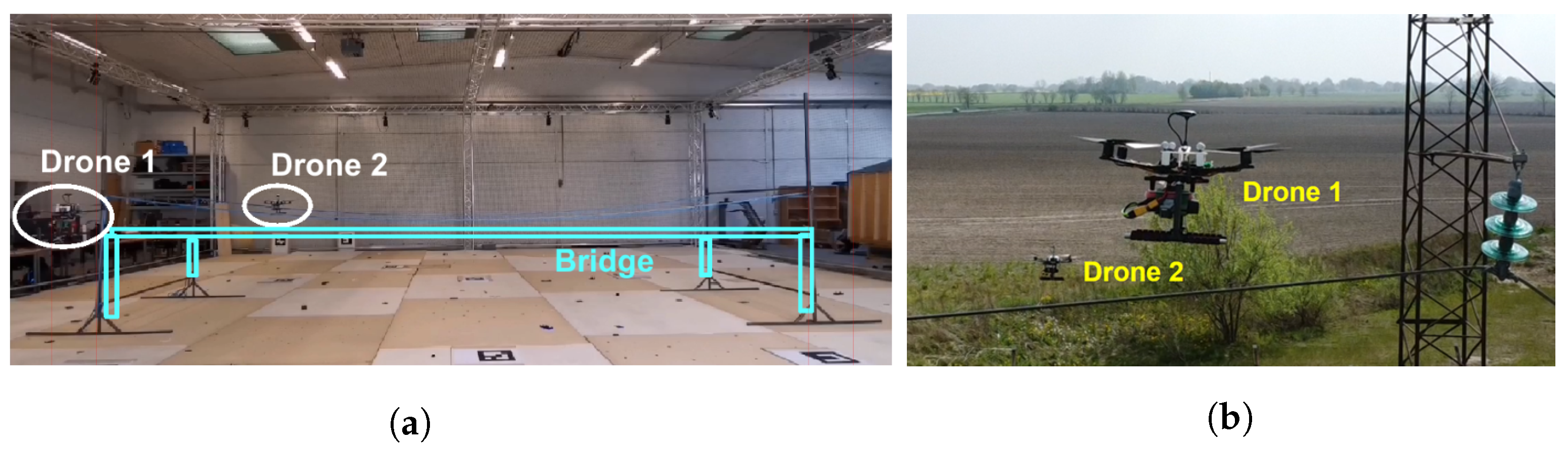
We test the formation flight function with two drones first in an indoor test environment (
Figure 14a) and at a later stage in an outdoor test near a powerline installation (
Figure 14b). The drone prototype for validating the swarming function is built based on the ModalAI VOXL platform and the S500 ARF Frame Kit. The drone hardware platform is based on the VOXL platform and implements the VOXL Flight Deck with onboard computer and Flight Core Flight controllers, stereo and tracking image sensors, and a GPS (outdoor) or Vicon motion capture system markers (indoor) with a body frame, motors, propellers, and ESCs. The ModalAI VOXL platform provides a self-contained low-level flight control allowing design and validation to focus on high-level control functions needed for the multi-drone system’s cooperative functions. We constructed a mockup of a bridge segment. Two drones estimate their state based on onboard sensors using visual inertial odometry tracking software. The two drones are controlled by their onboard computers while receiving mission commands from the GCS. Communication between the drones is established using WiFi. Formation flying is first demonstrated with vertical movement along the bridge pillars (modeled with vertical metallic bars) followed by horizontal movement along the bridge deck (blue ropes). The second pylon structure is inspected with another vertical movement and drones are hereafter landed safely.
It is observed that drones are moving synchronously from waypoint to waypoint. Two drones can respond to GCS mission commands in real time based on established communication. In the outdoor experiment (
Figure 14b), the two drones are conducting a powerline inspection. The communication setup and state estimation method are the same as the indoor experiment.
The video recording (
Video S2) of the formation flying with two drones demonstrates the cooperation of a powerline inspection mission. The two drones fly synchronously along the powerline allowing inspections from different viewpoints while keeping a fixed distance.
8.2. Messaging Service with a ROS Network
Efficient D2D communication is essential for achieving cooperation between drones in the swarm. Remote inter-process communication is evaluated by deploying the ROS/ROS2 publisher and subscriber respectively on two machines connected using WiFi: the Intel NUC8i3 with 16 GB RAM and an integrated wireless module (Intel Wireless-AC 9560) and the Intel NUC8i5 with 16 GB RAM and integrated wireless module (Intel Wireless-AC 9560). The ROS release Melodic Morenia, and the ROS2 release, Foxy Fitzroy, are the selected testing objects. The influence of changing WiFi mode, direct link using WiFi ad-hoc mode, and link passing through the WiFi access point with WiFi infrastructure mode are measured. Measurements are taken in an indoor environment in the presence of WiFi signals from other networks. Two machines are put on the table at a distance of one meter. To avoid inaccurate system synchronization between two machines, the latency is measured based on a round trip, of which the back trip is implemented by a direct C++ socket communication [
54].
We measured the communication latency with different message sizes. ROS2 Foxy shows a more stable latency than ROS Melodic on small message sizes (
Figure 15a,b). However, opposite results are observed when using large message sizes, especially on the size of 4M bytes (
Figure 15c,d).
Figure 16 shows the performance difference between the WiFi ad-hoc mode and the infrastructure mode. In the case of ROS Melodic, WiFi ad-hoc mode provides a more stable and shorter latency than using the WiFi access point on small message sizes.
8.3. Long-Range Radio Communication
Information about the path loss of a communication link is of critical importance as the attenuation in power is deciding if packets can be successfully received or not. The Packet Error Rate (PER) is likewise important as the payload could withhold time-critical information that should not be lost in transmission, or affect the performance of any potential application running above LoRa.
In the first experiment, we studied the effect of mounting the LoRa radio on a drone. In an anechoic chamber, we measured the signal loss due to the motor vibrations and blocking of the signal by the body frame of the drone. The drone was having the propellers spinning, making the drone almost takeoff. We determined a signal loss due to these impairments of about −3.5 dB [
55]. In the second experiment, the setup consisted of two Raspberry Pis, where one acts as a transmitter and the other as a receiver. This experiment does not use a drone as the effect of the drone has already been investigated in the first experiment.
The steps are as follows: (1) The transmitter and receiver are placed at a fixed distance from each other at the same elevation; (2) The transmitter sends a packet to the receiver; (3) The receiver waits for the packet to arrive and logs the Received Signal Strength Indicator (RSSI) and payload information; (4) Steps 2–3 are repeated
N times for the chosen Spreading Factor (SF) before a new distance is used.
Figure 17 summarizes the results for RSSI and PER measurements of LoRa at different distances between the transmitter and the receiver. The distances are measured by a GPS attached to each LoRa radio module. The PER is calculated by counting packets with bit errors in the payload data. RSSI values are shown as box plot symbols. The measurements are based on the statistics of 4000 samples at each distance.
The simplified path loss model is used as linear regression on the data samples. The model is shown below and used for obtaining the path loss exponent
n, and the shadowing effect
:
The shadowing effect
showed in Equation (
1) is a Gaussian distributed random variable with zero mean and the variance
. Based on our analysis, we find
m,
dBm,
,
with a
coefficient for the regression. The achievable data rate in this setting was 5.5 kbps based on a theoretical calculation. We find that this data rate is sufficient to support the communication of telemetry information between a drone and the GCS.
8.4. Automated Fault Detection with Deep Learning
We validate the performance of our proposed fault detection algorithm. For running deep learning models in a real-time environment, different single-board devices such as the Raspberry Pi 4, Nvidia Jetson Nano, Nvidia Jetson TX2, and Nvidia Jetson AGX Xavier were evaluated [
56]. For running the onboard vision-based fault detection algorithm, we used the Nvidia AGX NX Xavier board. AGX NX board is built with Volta architecture-based Graphics Processing Unit (GPU) having 384 Cuda cores and 48 tensor cores, and Carmel CPU. AGX NX can run deep learning model on GPU with 800 MHz frequency on 10 W and 1100 MHz frequency on 15 W.
The training of deep learning models requires more powerful GPUs with more resources. For the training of the YOLOv4-based fault detection algorithm, we use Nvidia Tesla V100 with 32 gigabytes, which consists of multiprocessors and is partitioned into four equal processing blocks to perform parallel computations. For the training of the proposed YOLOv4-based fault detection model, we use the configurations from [
57]. The momentum of the stochastic gradient descent is set to 0.9, the learning rate to 0.001, and the weight decay to 0.005. The images are scaled at 608 by 608 and the batch size is kept to 64. To keep the standardized learning rate of the neural network, the anchors that perform below the specified threshold value are dropped. For onboard real-time fault detection, we use Nvidia AGX NX, which performs detection at 11–17 FPS on different image scales [
57].
Figure 18 and
Figure 19 show the real-time onboard fault detection performance. The algorithm detects insulator objects with an accuracy in the interval from 0.75 to 0.99.
Figure 19 shows normal detected objects with yellow frames and detected faults with gray boxes. The broken powerline insulator is detected with an accuracy score of 0.99 and 0.98, respectively.
8.5. Cloud Services Support
This use case demonstrates interactions between a drone and cloud services. The first part of the demonstration involves mission planning, execution, and monitoring using both a simulated and a real drone. The experiment is conducted at Hans Christian Andersen Airport outside Odense in Denmark where the test setup consisting of a power line connecting two power towers is located (
Figure 20).
For experimental preparation, power tower locations were added to the graph structure as described in
Section 5.1. The drone reports its location, which is visualized on the web interface, by sending HTTPS requests to the cloud. The user of the web interface plans the mission by choosing the target power tower and calculating the route to reach it as shown in
Figure 21a. After the mission is planned, the user allows the drone to fetch the mission, and the drone starts executing the global plan by flying to the waypoints contained in it. The drone onboard control software is developed to follow received waypoints with an offset to avoid getting too close to the infrastructure. The drone continues reporting its location throughout the mission and the movement is visualized on the web interface allowing the user to monitor the mission’s progress. Mission monitoring is visualized at the beginning of the mission execution in
Figure 21b and the end in
Figure 21c.
The second part of the demonstration involves image transfer from the drone to the cloud. Two inspection scenarios could benefit from capturing and transferring images during the mission; the first scenario is where the fault detection algorithm is running on the drone’s onboard computer transferring detected faults through the cloud to the user. In the second scenario, the drone captures and transfers images to the cloud where they are stored and can be used for different types of analysis or three-dimensional reconstruction. When an image is received by the cloud, a pop-up button appears at the web interface alerting the user that a fault has been detected, and the user can immediately see it. The image is then stored in the object storage and can be retrieved after the mission upon user request through the search option offered on the web interface.
The demonstration video (
Video S3) shows the interactions between the cloud services and a single drone described in this section. The communication is successfully established in both directions, from the cloud to the drone by sending mission waypoints and from the drone to the cloud by reporting the drone location as well as infrastructure images. After accomplishing the simulated flight, we proceeded to the demonstration with a real vehicle. Although the test was successful, we experienced issues related to the wind that posed flight difficulties to the drone, and it was not flying as precisely as in the simulation. To tackle the aforementioned challenge, future work regarding cloud services would consider a weather service providing a real-time weather forecast for locations contained in the mission plan. Furthermore, drones should be equipped with the onboard controller adapting the flight trajectory for wind disturbances. Another encountered issue was data loss due to the interrupted connection.
8.6. Limitations of This Research
Several challenges and limitations need to be addressed before autonomous drone swarms can be operated routinely in civilian airspace. A UAS must have system redundancies and resilient functionality to ensure the overall safety and predictability of the system. A proof-of-concept for a UAS as the one presented here needs to undergo thorough review and testing in diverse environmental conditions to allow the design to develop high robustness and resiliency of operation through several design iterations. This concerns all subsystem designs including sensors, communication links, computation resources as well as their integration. Moreover, public acceptance of the integration of drones into society is demanding a high trust in technology. This trust can only be earned by increasing the awareness of opportunities and technical capabilities through demonstrations involving relevant stakeholders.
9. Conclusions
Inspection of critical infrastructure with a swarm of drones is an attractive innovation made possible with recent advances in electronics, communication, and computer technology. The European research and innovation project Drones4Safety (D4S) targets an increase in the safety of civil transport networks by designing a system of autonomous and cooperative drones for autonomous and continuous inspection. In this paper, we have reported on the design of a UAS to support safety-critical infrastructure inspections.
Drones are equipped with an onboard Multiprocessor System on a Chip (MPSoC) to enhance processing capabilities. Cameras and mmWave radar sensors are added to the drone system to improve navigation close to inspection objects. The software platform is based on ROS and provides low-level and high-level control parts of the drone. The inspection application interacts with the high-level control system to support algorithms including cable detection and identification, motion path planning, obstacle avoidance, formation flying, object and fault detection with AI, and swarm membership management. Drone-to-Drone (D2D) communication is used for cooperative functions and to support a high data rate wireless mesh with ranges of a few hundred meters. Drone-to-Ground (D2G) communication is used for telemetry reporting and is based on long-range wireless communication using LoRa. The drone swarm is loosely connected to a set of supporting Cloud Services using Drone-to-Cloud (D2C) communication offering internet access. The Cloud Services support autonomous inspection from a mission control point of view. Functions such as planning, monitoring, storage, and analysis services are key parts of this operational support. Cloud Services provide the interface between a remote human supervisor and the cooperative drone swarm.
Despite its large complexity, we find that the design of an autonomous cooperative drone swarm for critical infrastructure inspection is feasible given the current state of the art in electronic components, software, and communication technology. To raise the technology readiness level of our proposed autonomous drone swarm further, we will, in future work, focus on the robustness, durability, and scaling of the UAS. In addition, more emphasis will be put on the operational aspects, including compliance with European UAS traffic management system (UTM) services.


 ,
, 


