


Structural Behaviour of Aluminium–Timber Composite Beams with Partial Shear Connections

Institute of Building Engineering, Faculty of Civil and Transport Engineering, Poznan University of Technology, Piotrowo 5 Street, 60-965 Poznan, Poland
*
Authors to whom correspondence should be addressed.
Appl. Sci. 2023, 13(3), 1603; https://0-doi-org.brum.beds.ac.uk/10.3390/app13031603
Submission received: 9 December 2022
/
Revised: 17 January 2023
/
Accepted: 25 January 2023
/
Published: 27 January 2023
(This article belongs to the Special Issue Composite Structures - Modelling, Testing and Manufacturing)
Abstract
:In this paper, the short-term behaviour of innovative aluminium–timber composite beams was investigated. Laminated veneer lumber panels were attached to aluminium beams with screws. Recently conducted theoretical, experimental, and numerical investigations have focused on aluminium–timber composite beams with almost full shear connections. However, no experiments on aluminium–timber composite beams with partial shear connections have yet been conducted. For this reason, composite action in composite beams with different screw spacing was studied in this paper. Four-point bending tests were performed on aluminium–timber composite beams with different screw spacing to study their structural behaviour (ultimate load, mode of failure, load versus deflection response, load versus slip response, and short-term stiffness). The method used for steel–concrete composite beams with partial shear connection was adopted to estimate the load bearing capacity of the investigated aluminium–timber composite beams. The resistance to sagging bending of the aluminium–timber composite beams with partial shear connections from the theoretical analyses differed by 6–16% from the resistance in the laboratory tests. In addition, four 2D numerical models of the composite beams were developed. One model reflected the behaviour of the composite beam with full shear connection. The remaining models represented the composite beams with partial shear connections and were verified against the laboratory test results. Laminated veneer lumber was modelled as an orthotropic material and its failure was captured using the Hashin damage model. The resistance to sagging bending of the aluminium–timber composite beams with partial shear connections from the numerical analyses were only 3–6% lower than the one from the experiments.
1. Introduction
Aluminium and timber have a lower number of applications in civil engineering than in steel and concrete. Due to a new trend—sustainability in construction—new applications of these materials may gain in popularity. Both aluminium and timber have high strength-to-weight ratios. Aluminium is corrosion resistant and recyclable whereas timber is fully renewable and largely recyclable [1,2]. Aluminium elements are often extruded, which makes it possible to obtain any cross-section [3]. Recently, it has been demonstrated that aluminium can be combined with magnesium in one composite material to enhance the desired properties of both metals such as the strength-to-weight ratio [4,5]. Timber is produced in a wide range of shapes [6]. Furthermore, new engineered products made of wood such as laminated veneer lumber (LVL) [7], glued-laminated timber (glulam) [8] and cross-laminated timber (CLT) [9,10,11] have made it possible to overcome the size limitations of sawn timber. The use of engineered wood products also reduces the impact of naturally occurring wood defects (e.g., knots) [12]. Timber structural elements are easy to reinforce (e.g., by using glued wood-steel joints, glued wood-wood joints or carbon fibre reinforced polymer tapes) [13,14,15,16,17].
Aluminium and timber can be used together in one structure. Aluminium–timber composite mullion was developed by Jiao et al. for building façades [18]. In this solution, timber was used to improve the thermal performance of façade systems. Aluminium girders and timber slabs can be joined to obtain light composite floors. The lightness of this type of floor may speed up the construction process. The cooperation of timber slabs and aluminium girders eliminates stability problems (i.e., the local buckling in aluminium girder cross-sections and the lateral buckling of aluminium girders, in the case of simply supported beams). Slabs of aluminium–timber composite beams can be made of plywood, laminated veneer lumber or cross-laminated timber. Slabs and girders can be joined with self-drilling screws and adhesive epoxy materials [19], hexagon head wood screws, or bolts [20,21,22]. Adhesive epoxy materials should be used together with screws to avoid slab separation from girders at the high load value. This failure mode was observed at the ultimate load in the tests of steel–concrete composite beams with an adhesive material used as shear connection, as conducted by Kuczma [23]. The load-bearing capacity of aluminium girders increases significantly when they are joined with timber slabs (e.g., the load-bearing capacity of the unrestrained aluminium girders increased 6.3 times when they were attached to LVL slabs using screws) [24]. Chybiński and Polus demonstrated that it was possible to use screws or bolts as shear connectors to obtain composite beams with full shear connections [25,26]. An important advantage of these connectors is that they are demountable. The authors conducted four-point bending tests and investigated the failure load, mode of failure, load versus deflection, and load versus slip responses of the aluminium and timber composite beams. The shear resistance and stiffness of the bolted and screwed connections were studied in the accompanying push-out tests. The analysed connections were ductile and flexible. A theoretical method to calculate the load-carrying capacity of aluminium–timber composite beams with full shear connections was suggested and verified against the experimental results. The stress block method for steel–concrete composite beams from the EN 1994-1-1 standard [27] was improved to take into account the timber subjected to tension. However, some problems connected to aluminium–timber composite beams remain to be solved. The suggested connections are flexible. In the case of flexible connections, the slip between the girder and the panel is not negligible and its influence on the ultimate load and the stiffness of a composite beam should be evaluated [28,29,30]. Furthermore, the behaviour of aluminium and timber composite beams with partial shear connections calls for further investigation. Due to the fact that the thermal expansion coefficients of aluminium and timber are different, the impact of the thermal effects should be evaluated [31]. Furthermore, composite structural elements may require strengthening [32]. For this reason, guidelines for strengthening of aluminium–timber composite structures should be developed. Furthermore, the fire resistance of aluminium–timber composite elements should be investigated. Last but not the least, aluminium–timber composite structures should meet the requirements of sustainable construction.
Sustainability in construction is a very important trend in modern design [33]. Demountability is essential for sustainable construction. For this reason, new types of composite systems should be easily demountable at the end of their service life. Thanks to demounting, construction materials can be reused or recycled [34]. Steel and concrete composite beams have been widely used in civil engineering. Headed shear studs welded to the top flanges of steel girders are economical and easy to install, and, as a consequence, they are the most commonly used shear connectors [35]. However, the use of such headed studs makes the dismantling of composite beams nearly impossible, and beam components cannot be reused in the future. For this reason, demountable shear connectors for steel and concrete composite structures have been developed and investigated in recent years to facilitate the deconstructability of composite beams.
Lam, Dai, Saveri, Rehman, and Ashour [36,37,38,39,40] modified headed studs to develop demountable shear connectors. Similarly, Polus and Szumigała modified headed studs to create a new demountable shear connector for aluminium and concrete composite beams [41]. Due to the fact that no design guidance for composite beams with demountable shear connectors is currently available, Lam et al. [38] suggested applying the rules specified for headed shear studs and bolts in the EN 1994-1-1 [27] and EN 1993-1-8 [42] standards, respectively, to evaluate the load capacity of demountable shear connectors. Rehman et al. [40] compared the structural behaviour of a demountable composite floor system and a non-demountable composite floor system. The load-bearing capacity of both compared systems was similar, but the initial stiffness of the composite floor system with demountable shear connectors was lower than the one of the composite floor system with conventional headed studs. Based on their tests, Rehman et al. [40] demonstrated that the plastic resistance of the demountable composite floor system with partial shear connection can be obtained using the rectangular stress blocks method as well as the interpolation method.
Lee, Bradford, Liu, Ataei, Chen, and Ban [35,43,44] tested demountable shear connectors made of high-strength friction-grip bolts. Lee and Bradford [35] described the load–slip curve for a connection with pre-tensioned bolted shear connectors. The load–slip curve had three distinct sections. In the first section, the authors observed “full interaction” held by friction. In the second section, they noticed a region of “zero interaction” with slip corresponding to the clearance between the surrounding concrete and the bolts. In the last section, they discovered “partial interaction” because the bolts started to bear onto the concrete. Pavlović et al. [45,46] analysed the steel and concrete composite elements with high strength bolts. They conducted push-out tests and compared the bolts with headed studs. The load-carrying capacity of the shear connection with the bolts was 5% lower than the shear resistance of the connection with the headed studs. The stiffness of the connection with the bolts was 50% lower than the stiffness of the connection with headed studs [47]. The bolted shear connections were classified as brittle because the value of the characteristic ultimate slip was below 6 mm. Suwaed [48] investigated two types of demountable shear connectors that can be applied in precast steel–concrete composite bridges. Locking nut shear connectors and friction-based shear connectors had an important advantage—they facilitate replacing concrete slabs in the steel–concrete composite bridge. Kozma et al. [49] pointed out that demountable connectors should be replaceable due to the fact that damage of the connector tread could occur during transportation. If the connectors are not replaceable and they are damaged during transportation, not only the connectors but also the concrete slab is lost. For this reason, the authors demonstrated two shear connection types (the coupler system and the cylinder system). The initial stiffness of the systems was high (i.e., 70–100 kN/mm in the case of the coupler system and 250–500 kN/mm in the case of the cylinder system).
Demountable connectors were not only suggested for steel–concrete composite structures, but they were also applied in steel–timber composite structures and aluminium–timber composite structures. In the case of steel–timber composite structures, several types of demountable connectors were analysed (i.e., screws [50,51], bolts [52,53], and bolted shear connectors embedded in the grout [54]). Bolted shear connectors embedded in the grout had high ductility and energy-dissipating capacity when an adequate edge distance between the bolted shear connectors and the edge of the grout pocket in the timber slab were provided. In the case of aluminium–timber composite structures, similar demountable connectors were investigated (i.e., screws [25,55,56,57], bolts [26], screws with toothed plates [58], and bolts with toothed plates [59]). A comparison of the bolted and screwed connections was presented in [59]. In the case of both types of connections, the increase in the fastener diameter provided for the increase in the connection strength and its slip moduli. The bolted connection had a lower slip modulus k0.6 than the screwed connection due to the hole clearance. The bolted connections had an 80% higher shear strength than the screwed connections.
The structural performance of the composite floors significantly depends on the shear connection as it provides composite action. Recently conducted theoretical, experimental, and numerical investigations have focused on aluminium–timber composite beams with almost full shear connections. However, experiments on aluminium–timber composite beams with partial shear connections have not yet been conducted. In this paper, the composite action in composite beams with different screw spacing was studied. The analysed elements comprised aluminium beams and timber slabs to form T-shaped composite beams. Ten mm hexagon head wood screws were used to combine the composite beam components. Four-point bending tests were conducted on composite beams with different screw spacing. The degree of composite action was calculated taking into account the shear resistance of connectors investigated in the previous push-out tests. The method used for the steel–concrete composite beams with partial shear connection was adopted to estimate the load bearing capacity of the investigated aluminium–timber composite beams. The accuracy of this method was evaluated by comparing the results from the theoretical analysis with the results of three experiments. In addition, four numerical models of the composite beams were developed.
2. Materials and Methods
2.1. Aluminium Girders
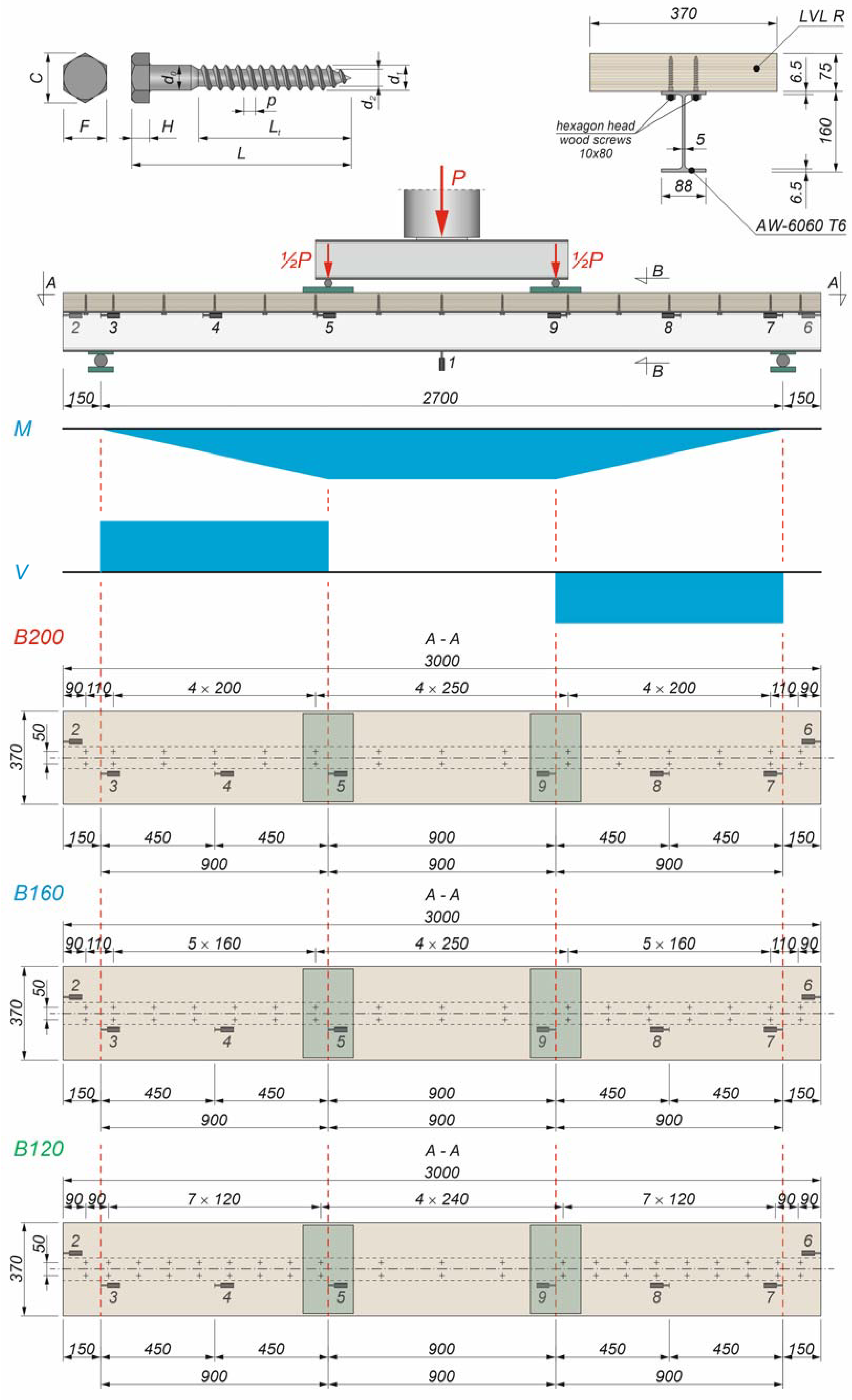
Aluminium extruded I-girders were made of AW-6060 T6 aluminium alloy. In accordance with the EN 1999-1-1 standard [60], the characteristic value of 0.2% proof strength f0.2 of this alloy was 140 MPa, the characteristic value of the tensile strength fu was 170 MPa, and the modulus of elasticity E was 70 GPa. The strength parameters of this alloy were also determined in tensile tests presented in [61] (Table 1).
2.2. Laminated Veneer Lumber Slabs
LVL is made of 3–4 mm wood veneers and adhesives [62]. In this paper, the authors used STEICO LVL manufactured in Poland from Scots pine and Norway spruce [63]. The tensile strength (parallel to grain), the compressive strength (parallel to grain), the bending strength (flatwise, parallel to grain), the modulus of elasticity, and the mean density of the LVL were 36.0 MPa, 40.0 MPa, 50.0 MPa, 14 GPa, and 550 kg/m3, respectively, based on the manufacturer’s declaration [63]. The mechanical parameters of LVL were also determined in tensile, compressive, and bending tests presented in [64] (Table 1).

Table 1.
The parameters of the materials used in the composite beams, determined in the previous laboratory tests [58,61,64].
| Parameter | Value |
|---|---|
| 0.2% proof strength of AW-6060 T6 | 186.7 ± 7.05 MPa |
| Tensile strength of AW-6060 T6 | 210.2 ± 2.90 MPa |
| Tensile strength (parallel to grain) of LVL | 41.9 ± 4.8 MPa |
| Compressive strength (parallel to grain) of LVL | 50.3 ± 1.6 MPa |
| Bending strength of LVL | 66.1 ± 6.9 MPa |
| Tensile strength of the steel used in the screws | 553.9 ± 23.6 MPa |
2.3. Screws
Hexagon head wood screws (often called coach or lag screws) were used in this study. The characteristic values of their tensile strength and yield strength were 500 MPa and 400 MPa, respectively, based on the screw grade (5.8). The tensile strength of the steel used in the screws was also determined in the tensile tests presented in [58] (Table 1).
2.4. Shear Connection Tests
The push-out tests of the shear connections were investigated in the previous tests presented in [58]. The connections had a characteristic slip capacity exceeding 6 mm, therefore they were ductile. The ultimate load per one connector was 16.7 ± 0.9 kN and the slip corresponding to this load was 16.7 ± 7.3 mm. The values of the slip moduli per one connector k0.4 and k0.6 were 6.6 ± 4.1 kN/mm and 6.2 ± 3.1 kN/mm, respectively [58].
2.5. The Experimental Programme of the Study
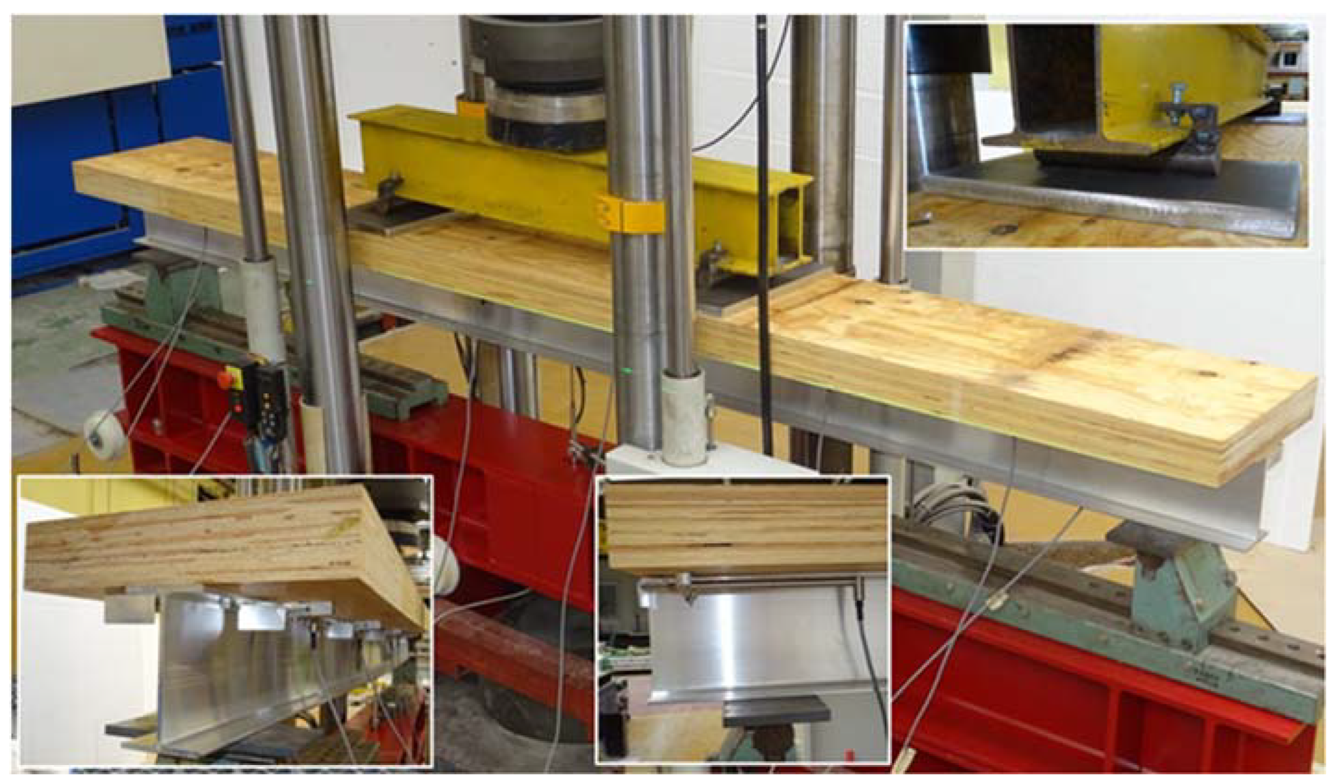
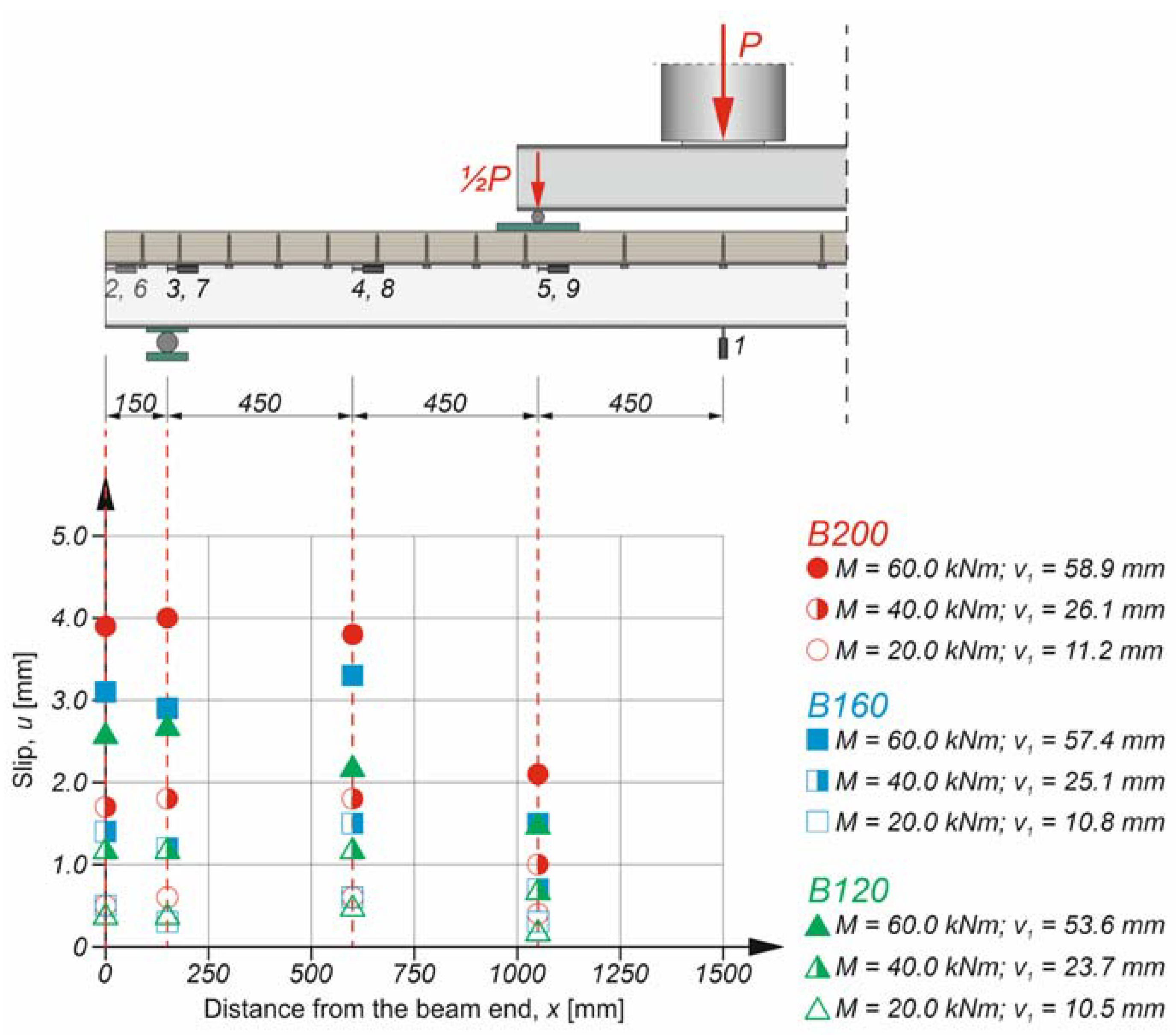
Four-point bending tests were conducted on three aluminium–timber composite beam specimens with different screw spacing (Figure 1).
The beams were tested using an Instron 8505 Plus machine (Instron, High Wycombe, Buckinghamshire, UK). Each composite beam consisted of an LVL slab and an extruded beam made of an AW-6060 T6 aluminium alloy. The dimensions of the analysed beams were identical. However, the number of shear connectors and their spacing were different (Figure 2). Nine linear variable differential transformers (LVDTs) were used to measure the deflection and the slip between the LVL panel and the aluminium beam. A spreader beam was used to obtain pure bending of the composite beams between the loading points (when the shear from the dead load was not taken into account). The composite beams were located on roller supports. Steel plates were used in each support to prevent the local yielding of the girder flange. The 10 mm clearance holes were drilled through the top flanges of the aluminium beams. The diameter of the pre-drilled holes in the LVL slabs was 7 mm. The pre-drilled holes made it easier to install the screws. The transverse screw spacing was 50 mm. The longitudinal spacing was different for each beam (i.e., 120 mm, 160 mm, and 200 mm). Based on the connector spacing, the tested beams were designated as B120, B160, and B200. The authors of this paper used a torque wrench (Sandvik Belzer, IZO-I-100, 10–100 N·m, Sandvik, Portlaoise, Ireland) and a torque moment of 40.0 N⋅m to install the screws. Due to the fact that the torque wrench was used, all screws were tightened with the same torque moment and LVL was not crushed during screw installation. The loading procedure consisted of two steps. In step one, the composite beams were loaded to ca. 20 kN and then unloaded to ca. 5 kN. In step two, the beams were loaded up to the failure point. In step one, the clearances in the beam connections were reduced. In each step, a displacement control regime and a piston velocity of 1.0 mm/min were used to evaluate the behaviour of the analysed beams after the failure load had been achieved.
2.6. The Numerical Models
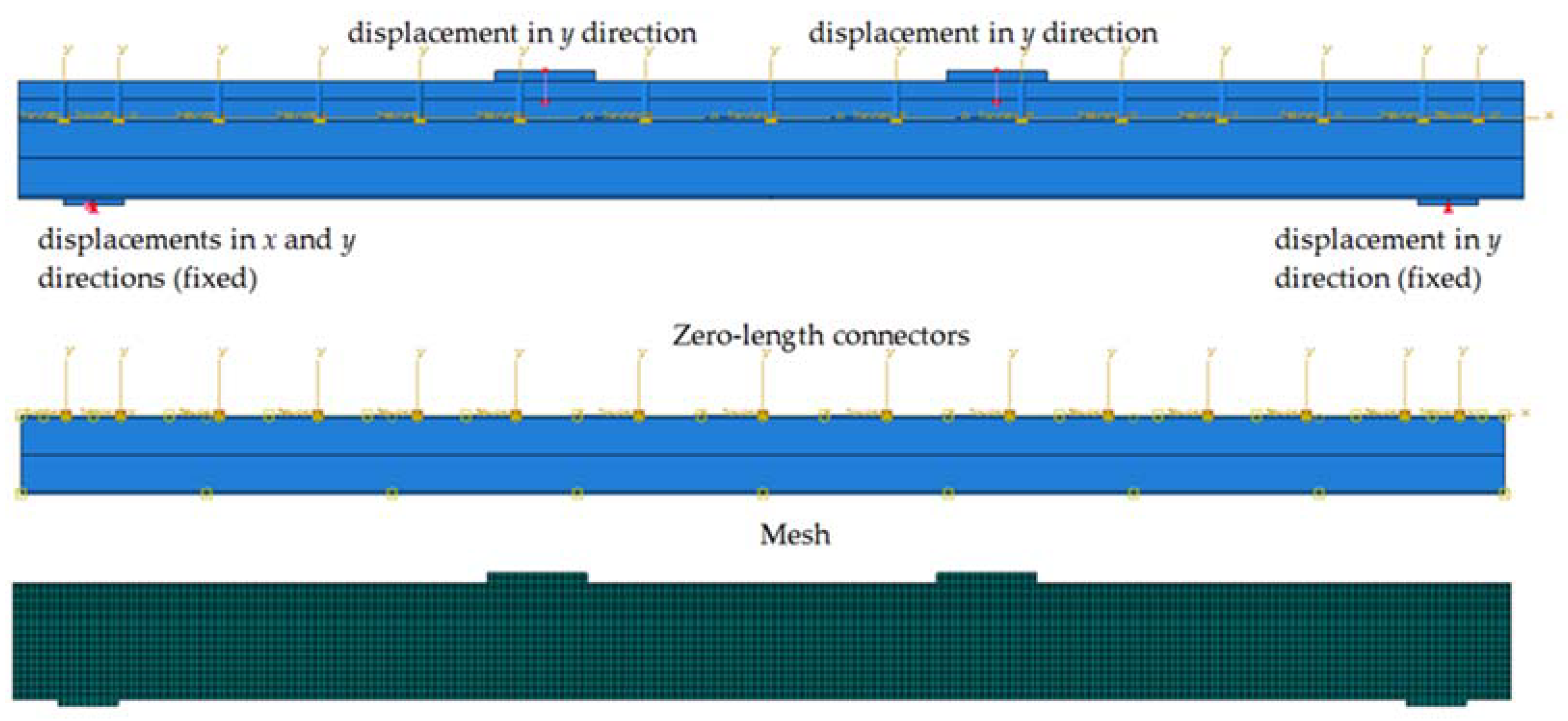
Four 2D numerical models of aluminium–timber composite beams were developed in Abaqus software (Figure 3). The first model represented the composite beam with full shear connection. In this model, a slab was connected with a girder using a tie function. A continuous tie type of interaction is often adopted in the case of full composite action in composite beams [65]. The numerical models 2–4 represent composite beams with partial shear connections tested in the present study.
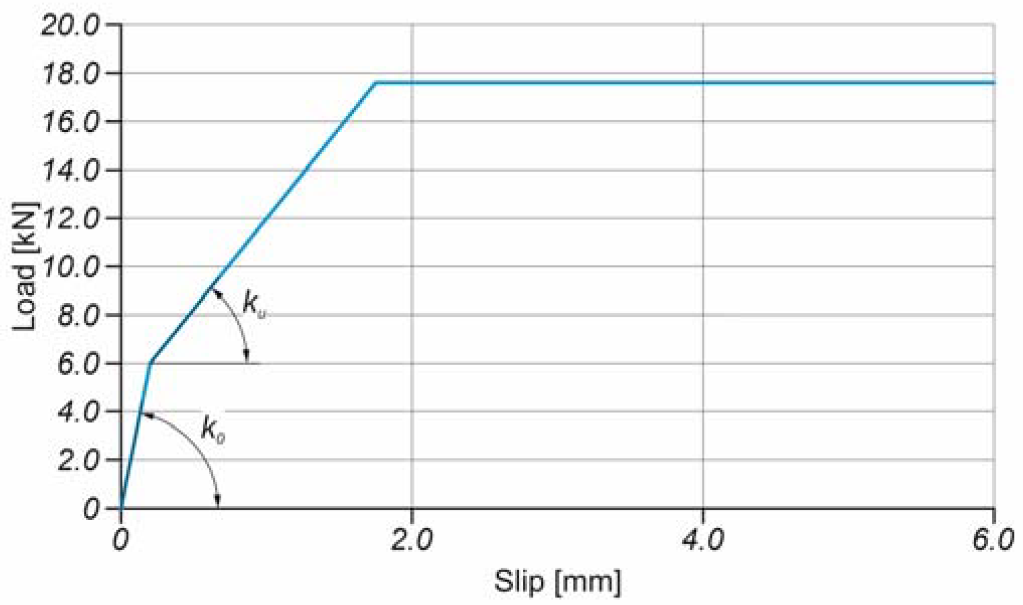
Discrete connections were used to model shear connections and to take slip into account. Discrete connections are often used in numerical models because they provide reasonable accuracy in reflecting the behaviour of the real structure [66,67]. At each point corresponding to the locations of the screws, the LVL slabs and the aluminium girders were connected using zero-length translator-type connectors. This type of connector makes it possible for the connected elements to move only in one direction (i.e., in the longitudinal direction). For each discrete connection, the forces and displacements from Figure 4 were used. The slip modulus ku was calculated from Eurocode 5 [68]:
where n is the number of connectors in one connection (2 in the analysed beams); ρm is the mean density of LVL; d is the diameter of the screw.
The value of the slip modulus k0 was assumed to be 30 kN/mm for the slip ranging from 0 to 0.2 mm to take into account the low initial slip values observed in the beams in the laboratory tests.
Additionally, steel elements representing the screws were embedded in the LVL slabs to consider the presence of the screws in the slabs. The loading and supporting steel plates, the aluminium girders, and the LVL slabs were modelled using 4-node bilinear plane stress quadrilateral elements with reduced integration and hourglass control (CPS4R). The screws were modelled using T2D2 linear line elements. The mesh size did not exceed 5 mm. The interaction between beam parts was captured by surface-to-surface “hard” contacts and friction contacts. In the case of the LVL–aluminium interface, the friction coefficient equal to 0.3 was adopted, just like for the LVL–steel frictional interaction [52,69]. In the case of the steel–aluminium interface, a friction coefficient equal to 0.3 was used. Figure 5 presents the boundary conditions used in the numerical analyses.
The aluminium yielding was modelled by an elastic-isotropic hardening plastic constitutive law (E = 70 GPa, fy = 186.7 MPa, fu = 210.2 MPa). The steel was modelled as a bi-linear elastic-perfectly plastic material (E = 210 GPa, fy = 235 MPa). The LVL was treated as an orthotropic material. The Hashin damage model was used to capture the failure of the LVL. The material properties of the LVL adopted in the numerical models are provided in Table 2.
3. Results and Discussion
3.1. The Results of the Four-Point Bending Test
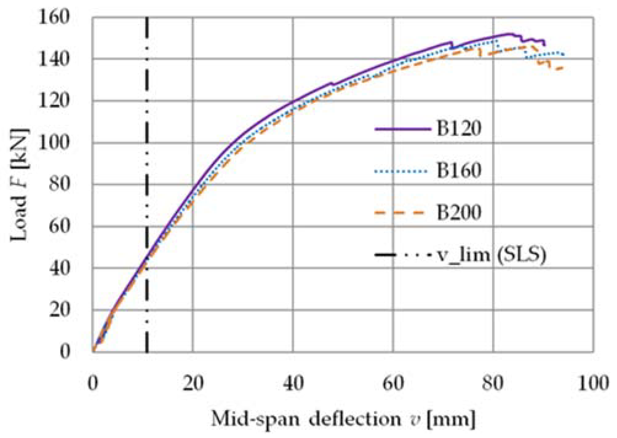
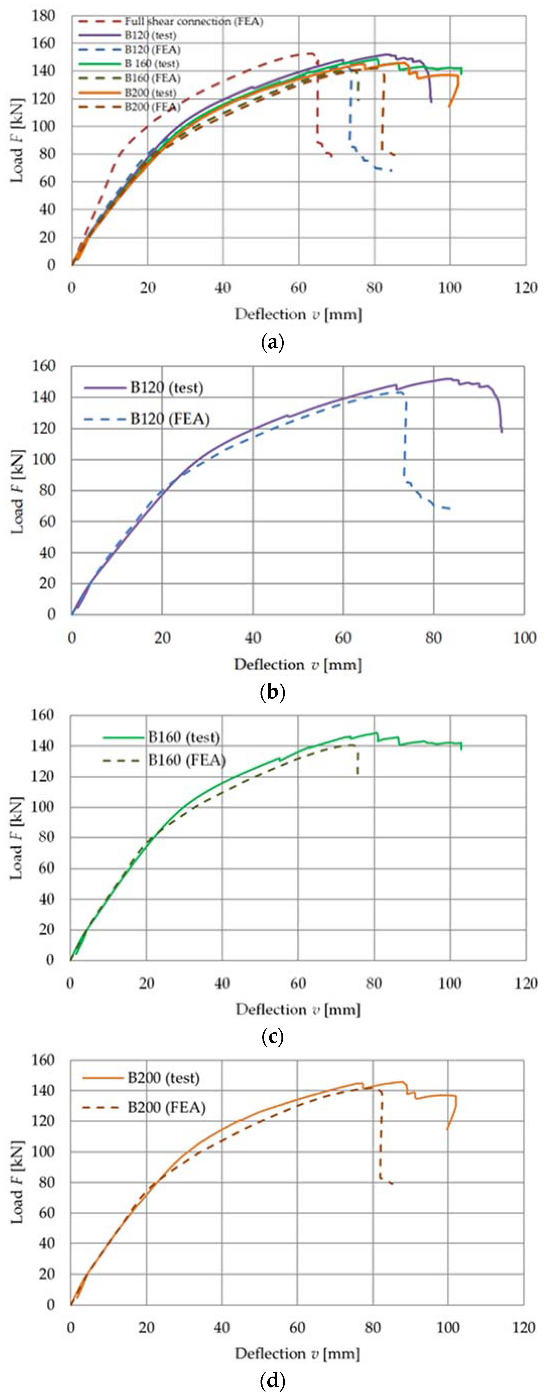
The results of the experimental study are presented in Figure 6 and Figure 7, and in Table 3. Figure 6 shows the load versus deflection response from the bending tests.
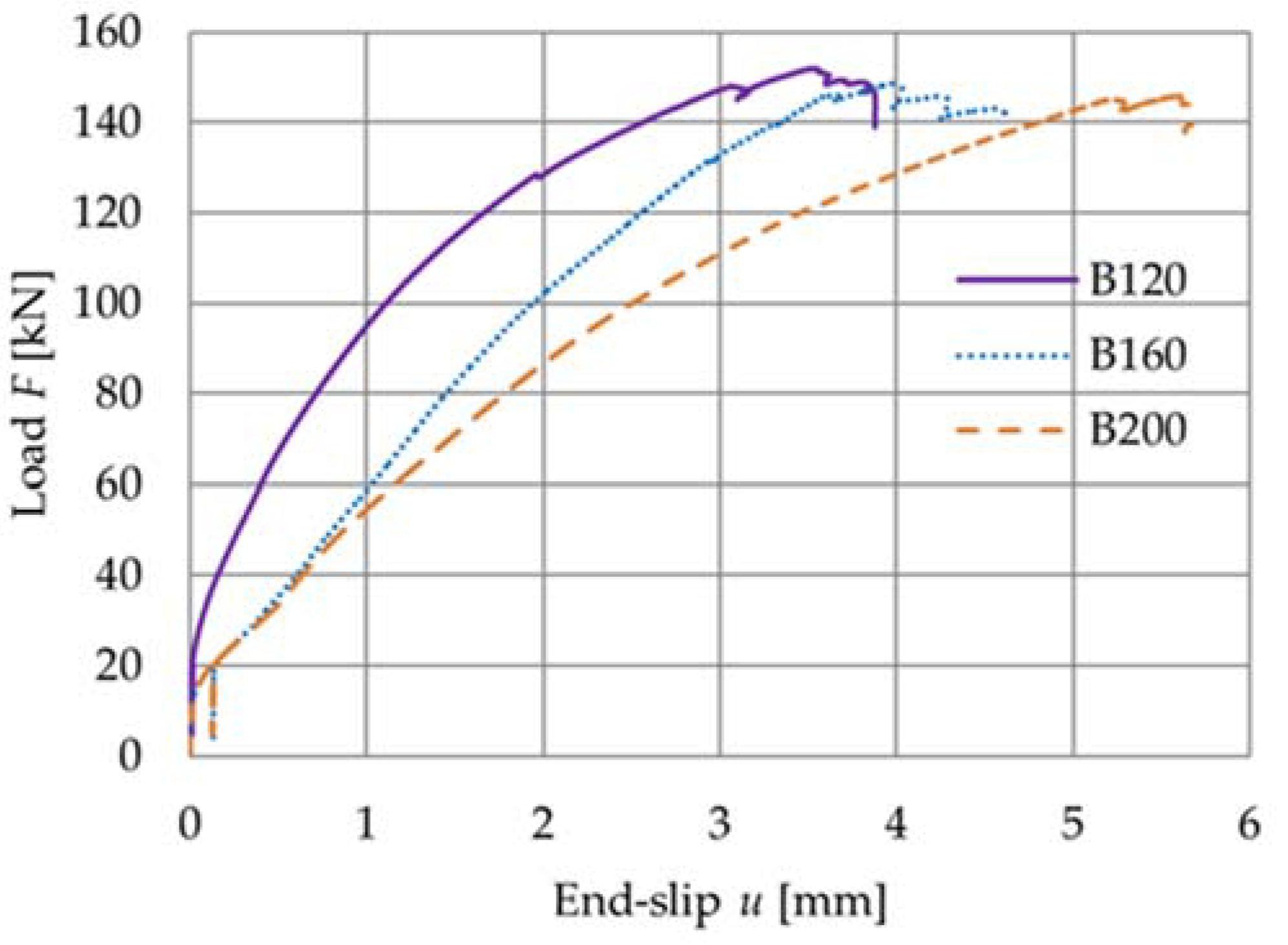
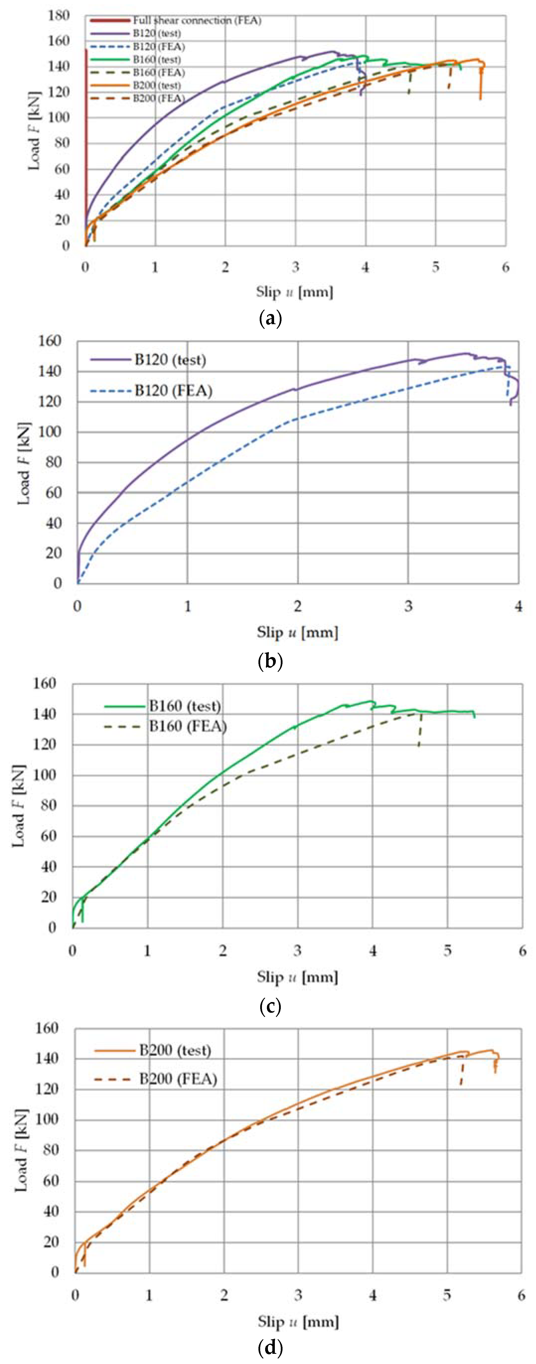
Figure 7 shows the load versus slip response from the bending tests.
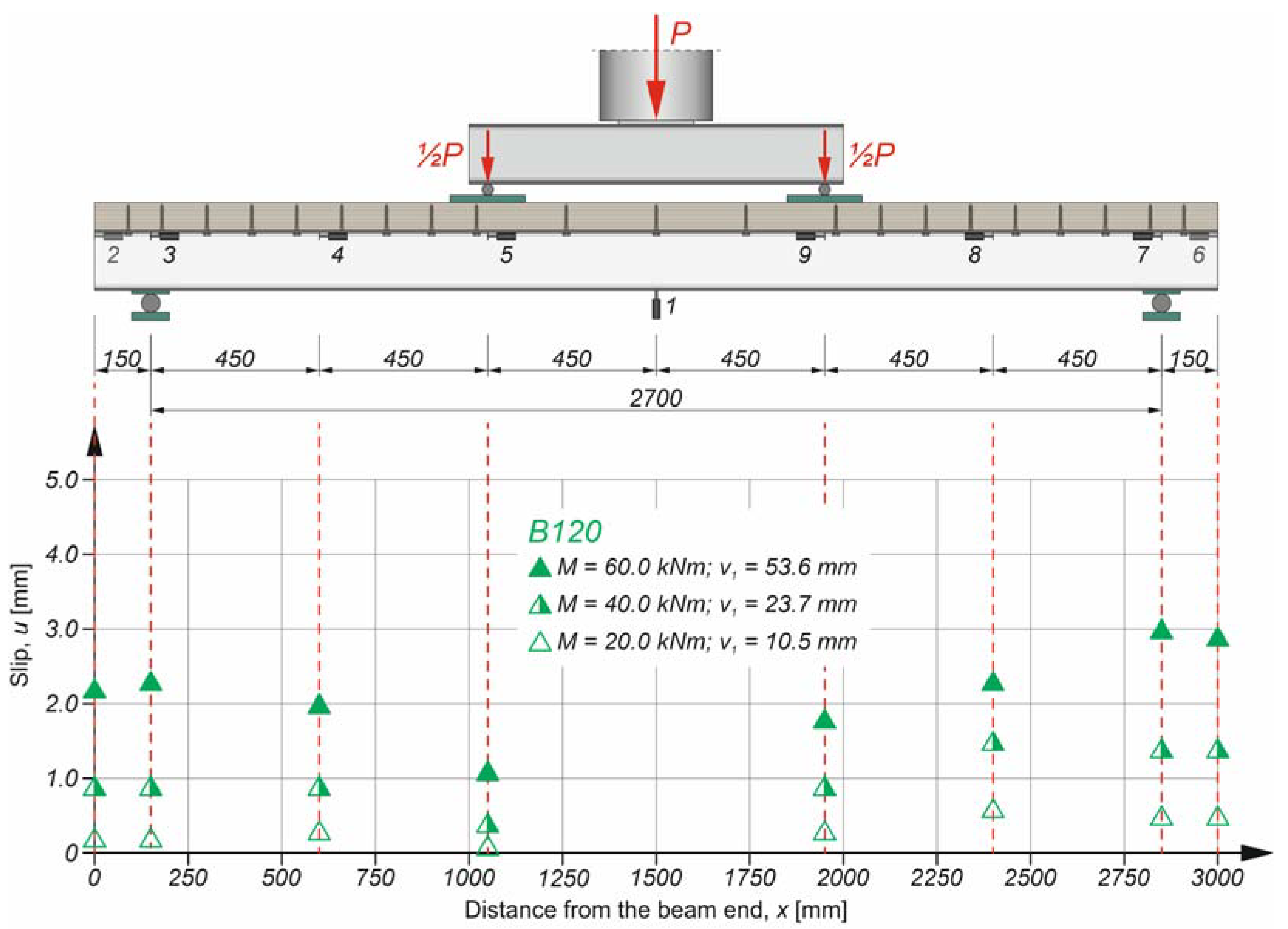
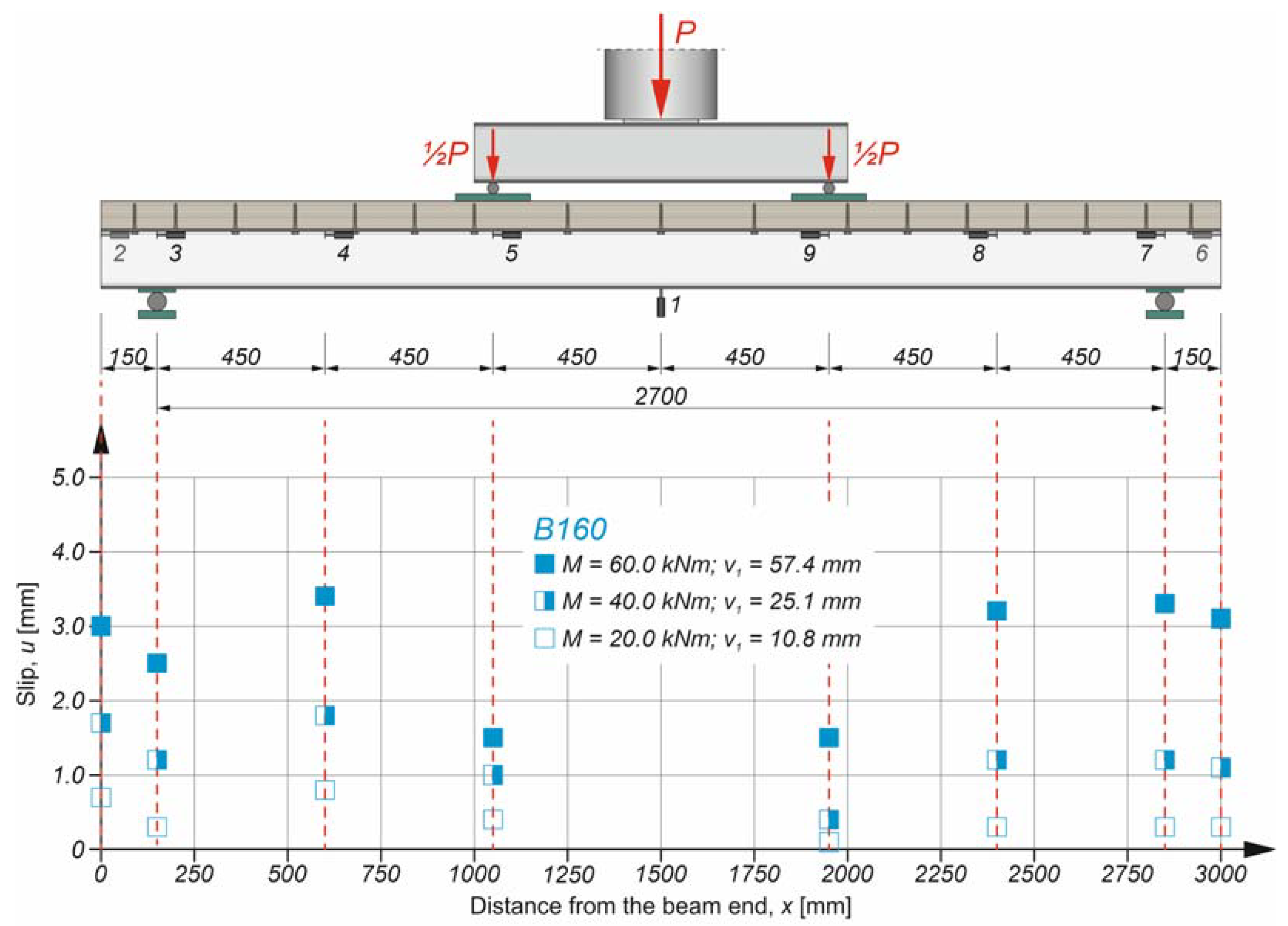
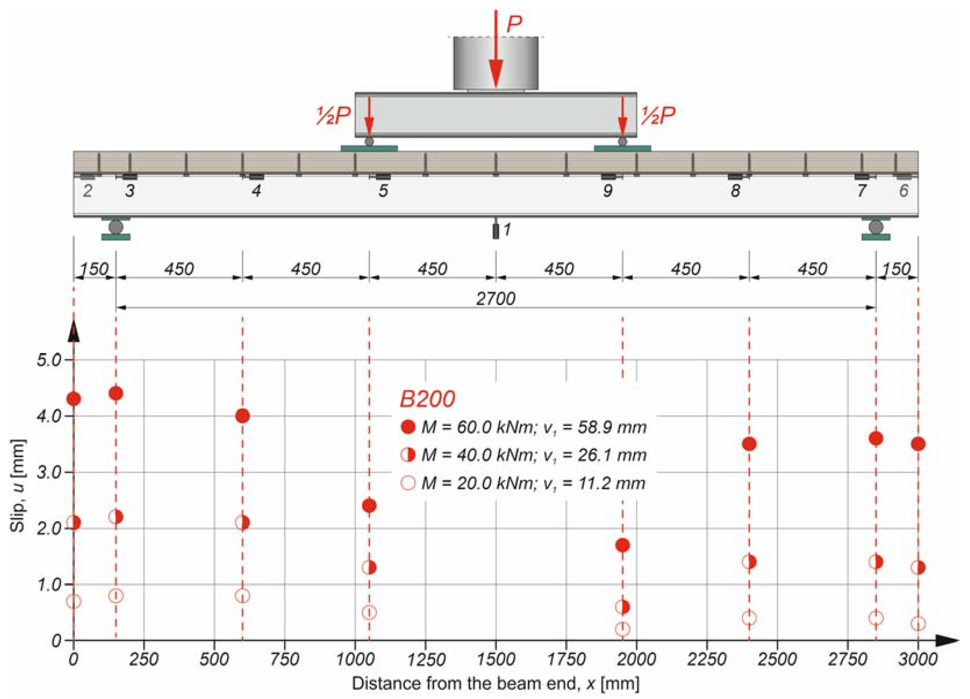
Figure 8, Figure 9 and Figure 10, present the slip distribution in the interface of the analysed beams. The slip distribution was not constant because the highest value of the slip was near the support. The obtained slip distribution curve is typical of composite beams with flexible connections [70].
Figure 11 presents the comparison of the mean slip values in the interface of the analysed beams. The mean values of the slip were calculated considering the slip values from the left and right sides of the beams. The degree of shear connection had an impact on the slip value. Beam B200 had the highest slip value, which resulted from the lowest value of the degree of shear connection.
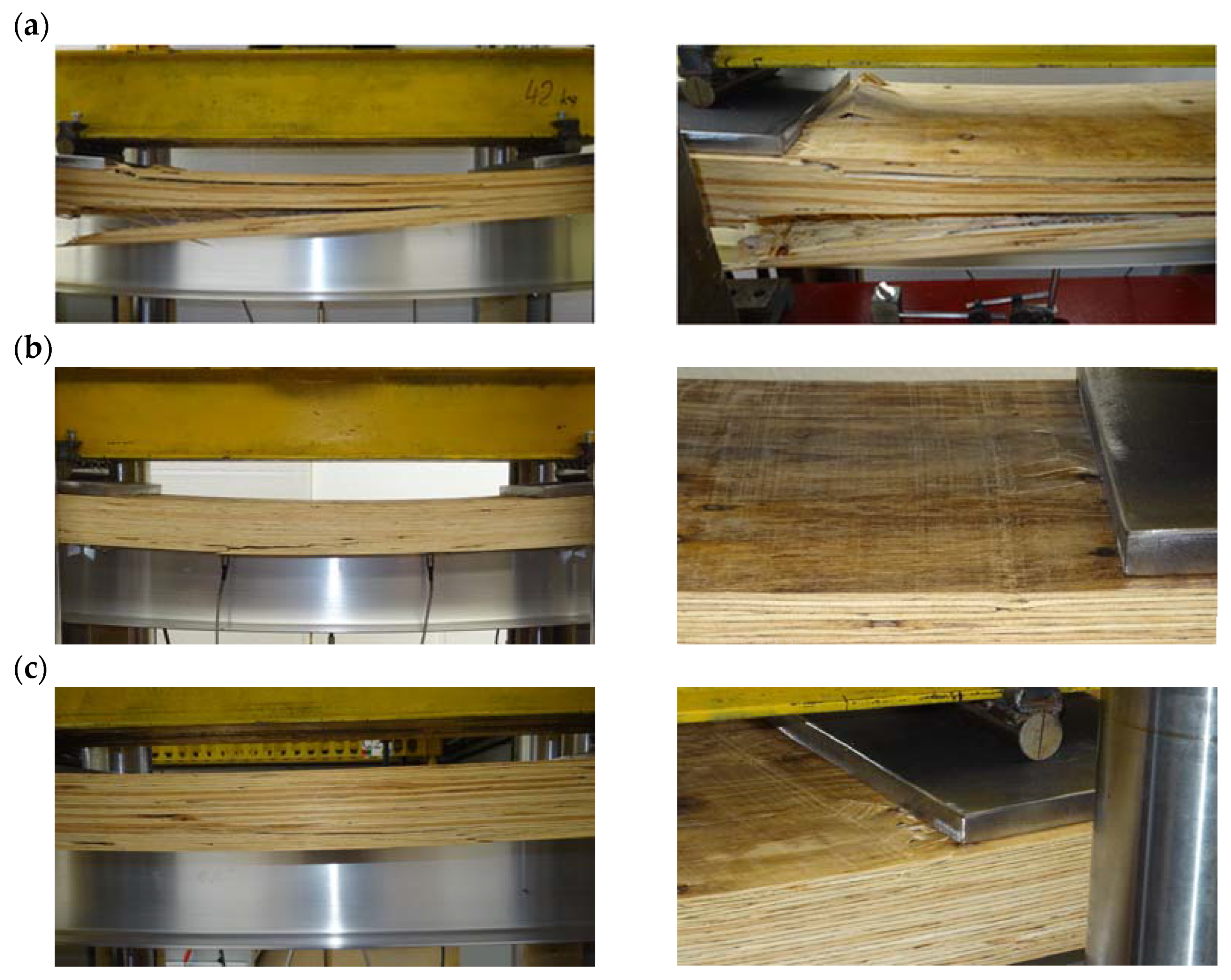
The authors observed one distinctive mode of failure in all of the tested beams (Figure 12). When the collapse load was applied, the veneers separated from each other in the LVL panel sections subjected to tension. Then, the veneers cambered near the loading plates in the LVL panel sections subjected to compression. At the serviceability deflection limit (L/250 = 10.8 mm), the load reached ca. 30% of the failure load. The deflections of the specimens were large because of the low values of the modulus of elasticity for aluminium and LVL. The Young’s modulus of aluminium (70 GPa) is three times lower than that of steel (210 GPa). For this reason, the deflection of the tested beams was large. However, in the presented tests, the LVL slab width was limited by the dimensions of the laboratory stand. The LVL slabs were located between the columns of the testing machines. The dimensions of the LVL panel and the cross-section of the aluminium beam were selected to obtain the neutral axis located in the LVL. In the case of the floor, the effective LVL slab will be wider, and the girder will be higher. As a result, the deflections will be lower. Therefore, the combination of aluminium and timber is beneficial. The transformed slab area for the cross-section of an aluminium–timber composite beam is approximately three times larger (n = 70.0/14.0 = 5.0) than the transformed slab area for the cross-section of a steel–timber composite beam (n = 210.0/14.0 = 15.0). This means that the second moment of area of an ideal cross-section of a composite beam is larger for an aluminium and timber composite beam than for a steel and timber composite beam. Due to this fact, the impact of the low modulus of elasticity of aluminium on large deflection may be decreased.
3.2. The Theoretical Load-Carrying Capacity of the Aluminium–Timber Composite Beams with Partial Shear Connection
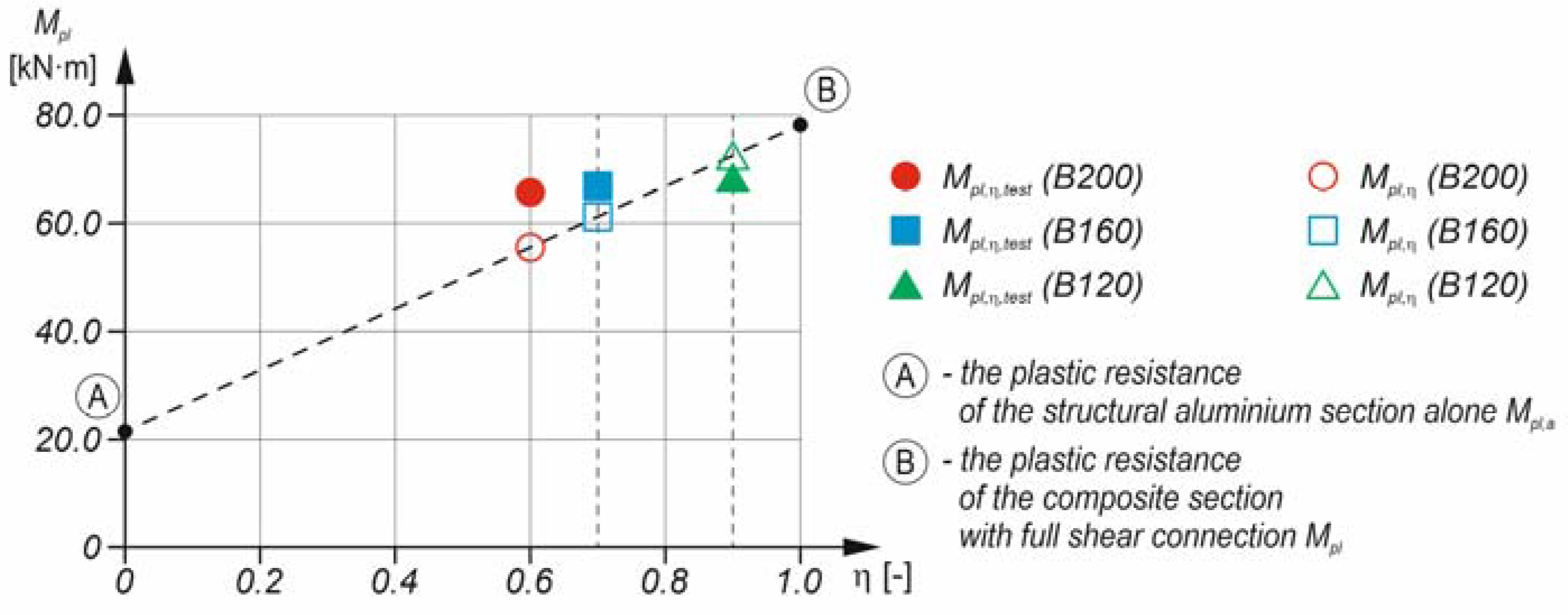
The plastic resistance to bending of the aluminium–timber composite beam with partial shear connection Mpl,η was calculated based on the method for the steel and concrete composite beams presented in [27]:
where Mpl,a is the plastic resistance to sagging bending of the structural aluminium section alone; Mpl is the plastic resistance to sagging bending of the composite section with full shear connection; η is the degree of the shear connection.
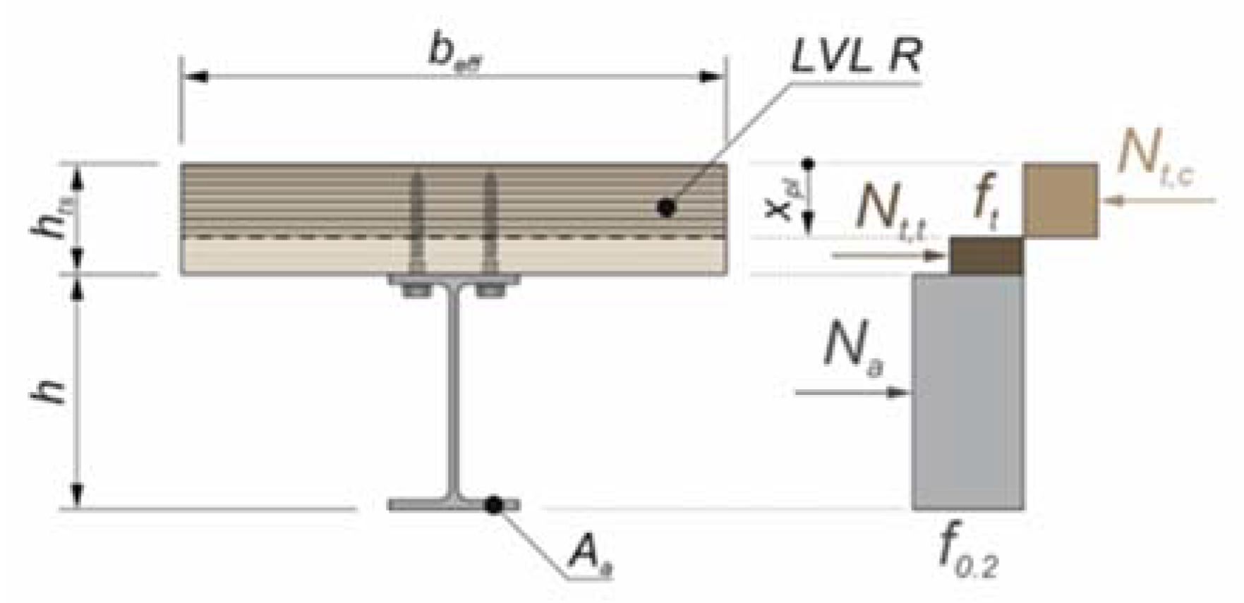
The calculations of the plastic resistance of the aluminium–timber composite beam were conducted using the stress block method for the steel–concrete composite beams (Figure 13) and are presented in Table 4. The timber subjected to tension was additionally taken into account. Due to fact that the LVL slabs were subjected to both tension and compression in the composite beams with partial shear connections, the bending strength of the LVL was used as the LVL strength. This assumption was made based on the fact that timber structural elements are stronger in bending than in compression or tension [71]. This is because when a timber structural element is subjected to bending, only about 10% of its volume is subjected to high stresses, whereas when a timber structural element is subjected to pure tension or compression, all of its volume is subjected to the same value of stress [72].
The plastic resistance to sagging bending of the aluminium–timber composite beam was calculated from [25]:
The calculations of the plastic resistance of the aluminium–timber composite beam with partial shear connection are presented in Table 5. The normal force in the aluminium beam section was 18.79 · 18.7 = 351.0 kN. The degree of the shear connection was η = 18 · 17.6 = 316.8 kN/351.0 = 0.90, η = 14 · 17.6 = 246.4 kN/351.0 = 0.70, η = 12 · 17.6 = 211.2 kN/351.0 = 0.60, and because it was lower than 1.0, the analysed elements were composite beams with partial shear connections. Two connectors located in the overhang portion of the beam were also taken into account as they reduced the slip between the girder and the slab. The calculated plastic resistance of the aluminium section Mpl,a was 21.5 kN·m (Wpl · f0.2 = 114.8 · 18.7 = 21.5 kN·m). The resistance to sagging bending of the aluminium–timber composite beams with partial shear connections from the theoretical analyses differed by 6–16% from the resistance in the laboratory tests (Figure 14).
3.3. The Results of the Numerical Analyses
The comparison of the plastic resistance of the aluminium–timber composite beams to sagging bending obtained in the theoretical, experimental, and numerical simulations is presented in Table 6.
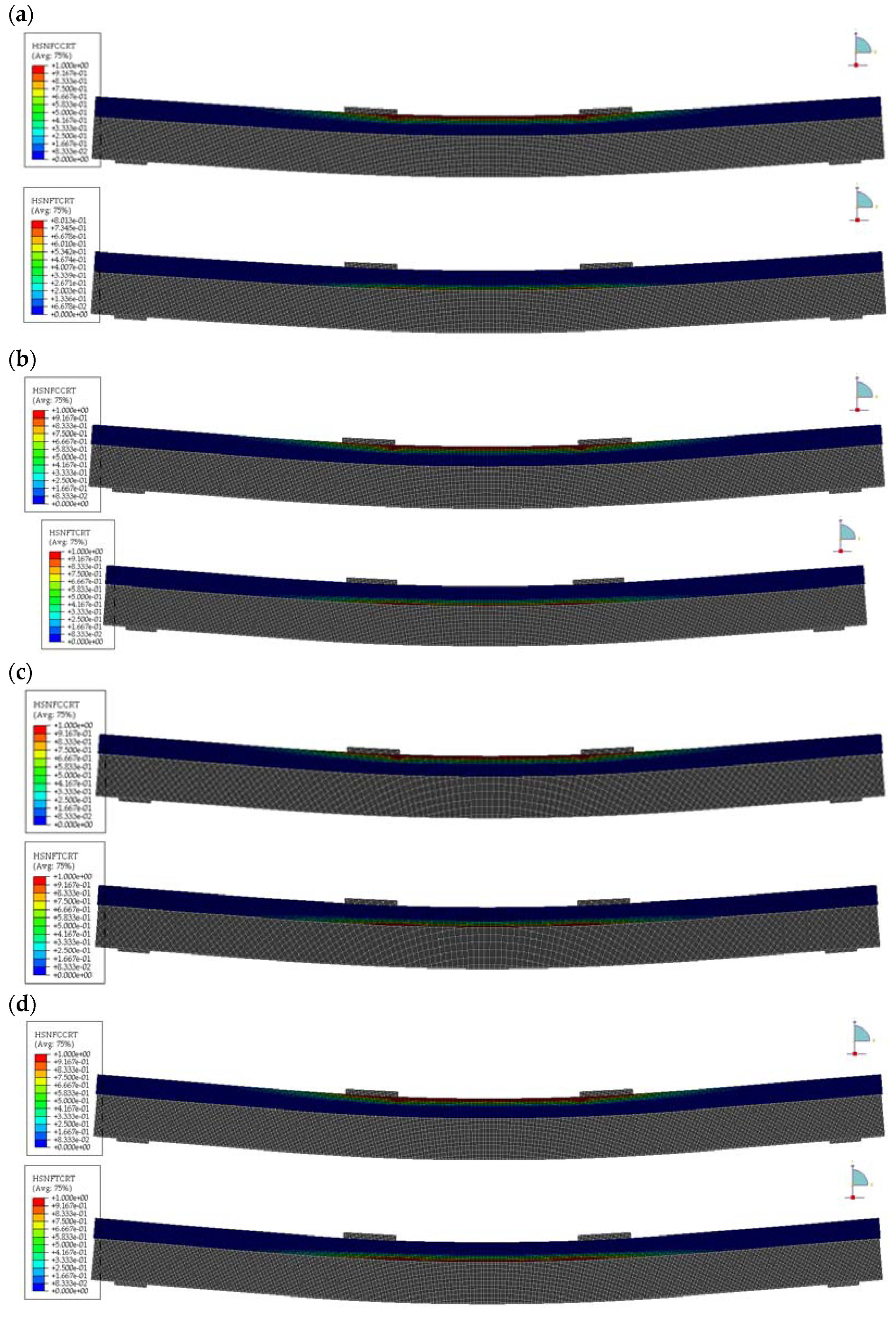
Figure 15 shows the load versus deflection responses, while Figure 16 shows the load versus slip responses from the bending tests and the numerical simulations. The damage of the LVL was taken into account in the numerical simulations thanks to the use of the Hashin damage model. Figure 17 presents the damage initiation variables (HSNFTCRT is the maximum value of the fibre tensile initiation criterion, HSNFCCRT is the maximum value of the fibre compressive initiation criterion [73]). The failure mode of the composite beams obtained in the numerical analyses was the same as the one from the laboratory tests. One can observe the damage of veneers in the sections of the LVL slab subjected to the highest tensile stress and the highest compressive stress near the loading plates. In the composite beam with full shear connection (analysis 1), the section of the LVL slab subjected to tension was smaller than in the composite beams with partial shear connections.
4. Conclusions
The authors of this article studied the structural behaviour of aluminium–timber composite beams with partial shear connections. They observed the failure modes of the tested beams, resulting from the veneer separation in the tensile zones and the veneer cambering in the compressed zones of the LVL slabs both in the laboratory tests and in the numerical analyses. The analysed beams differed in the degree of shear connection, which had a strong impact on the end-slip. However, the values of the ultimate load of the composite beams were similar because flexible connections were used and the degree of the sheer connection of each beam was higher than 0.4.
The method for the steel–concrete composite beams with partial shear connection was used for the aluminium–timber composite beams with partial shear connection, and the difference between the calculated and the test results was 6–16%.
The numerical models of the composite beams were verified against the laboratory test results. The resistance to sagging bending of the analysed composite beams with partial shear connections from the numerical analyses was only 3–6% lower than the one from the experiments. The load–deflection and the load–slip responses of the composite beams in the numerical analyses were similar to the ones from the tests due to the fact that the failure of the LVL was captured using the Hashin damage model and the connections were modelled discreetly.
The study presented in this paper has certain limitations as only three aluminium–timber composite beams were tested, and they all showed a high degree of shear connection. Future tests should focus on composite beams with lower degrees of shear connection.
Author Contributions
Conceptualization, M.C. and Ł.P.; Methodology, M.C. and Ł.P.; Investigation, M.C. and Ł.P.; Specimen preparation, M.C. and Ł.P.; Writing—original draft preparation, M.C. and Ł.P.; Writing—review and editing, M.C. and Ł.P.; Visualization, M.C. and Ł.P. All authors have read and agreed to the published version of the manuscript.
Funding
This research was funded by the Polish Ministry of Science and Higher Education under grant 0412/SBAD/0060.
Institutional Review Board Statement
Not applicable.
Informed Consent Statement
Not applicable.
Data Availability Statement
All data are contained within the article.
Acknowledgments
The authors wish to thank STEICO for the LVL slabs.
Conflicts of Interest
The authors declare no conflict of interest.
References
- Mazzolani, F.M. 3D aluminium structures. Thin-Walled Struct. 2012, 61, 258–266. [Google Scholar] [CrossRef]
- Siwowski, T. FEM modelling and analysis of a certain aluminium bridge deck panel. Arch. Civ. Eng. 2009, 55, 347–365. [Google Scholar]
- Dokšanović, T.; Džeba, I.; Markulak, D. Applications of aluminium alloys in civil engineering. Tech. Gaz. 2017, 24, 1609–1618. [Google Scholar] [CrossRef]
- Rahmatabadi, D.; Tayyebi, M.; Najafizadeh, N.; Hashemi, R.; Rajabi, M. The influence of post-annealing and ultrasonic vibration on the formability of multilayered Al5052/MgAZ31B composite. Mater. Sci. Technol. 2021, 37, 78–85. [Google Scholar] [CrossRef]
- Rahmatabadi, D.; Ahmadi, M.; Pahlavani, M.; Hashemi, R. DIC-based experimental study of fracture toughness through R-curve tests in a multi-layered Al-Mg (LZ91) composite fabricated by ARB. J. Alloys Compd. 2021, 883, 160843. [Google Scholar] [CrossRef]
- Harte, A.M. Timber engineering: An introduction. In ICE Manual of Construction Materials: Volume I/II: Fundamentals and Theory; Concrete; Asphalts in Road Construction; Masonry; Forde, M., Ed.; ICE Publishing: London, UK, 2009. [Google Scholar]
- Wang, X.; Zhang, J.; Wu, P.; Li, Y. Experimental investigation on the flexural and shear behaviour of LVL I-beam strengthened with steel channels. Constr. Build. Mater. 2022, 341, 127719. [Google Scholar] [CrossRef]
- Fonseca, E.M.M.; Leite, P.A.S.; Silva, L.D.S.; Silva, V.S.B.; Lopes, H.M. Parametric Study of Three Types of Timber Connections with Metal Fasteners Using Eurocode 5. Appl. Sci. 2022, 12, 1701. [Google Scholar] [CrossRef]
- Bao, Y.; Lu, W.; Yue, K.; Zhou, H.; Lu, B.; Chen, Z. Structural performance of cross-laminated timber-concrete composite floors with inclined self-tapping screws bearing unidirectional tension-shear loads. J. Build. Eng. 2022, 55, 104653. [Google Scholar] [CrossRef]
- Abdoli, F.; Rashidi, M.; Rostampour-Haftkhani, A.; Layeghi, M.; Ebrahimi, G. Withdrawal Performance of Nails and Screws in Cross-Laminated Timber (CLT) Made of Poplar (Populus alba) and Fir (Abies alba). Polymers 2022, 14, 3129. [Google Scholar] [CrossRef]
- Aspila, A.; Heinisuo, M.; Mela, K.; Malaska, M.; Pajunen, S. Elastic design of steel-timber composite beams. Wood Mater. Sci. Eng. 2022, 17, 243–252. [Google Scholar] [CrossRef]
- Derkowski, A.; Kuliński, M.; Trociński, A.; Kawalerczyk, J.; Mirski, R. Mechanical Characterization of Glued Laminated Beams Containing Selected Wood Species in the Tension Zone. Materials 2022, 15, 6380. [Google Scholar] [CrossRef] [PubMed]
- Lokaj, A.; Vavrusova, K. Longitudinal bonded joints of timber beams using plywood and LVL plates. Procedia Struct. Integr. 2017, 5, 1363–1369. [Google Scholar] [CrossRef]
- Rapp, P. Application of adhesive joints in reinforcement and reconstruction of weakened wooden elements loaded axially. Drewno 2016, 59, 59–73. [Google Scholar] [CrossRef]
- Lokaj, A.; Klajmonová, K. Round timber joints exposed to static and dynamic loading. Wood Res. 2014, 59, 439–448. [Google Scholar]
- Kula, K.; Socha, T. Renovation and strengthening of wooden beams with CFRP bands including the rheological effects. Civ. Environ. Eng. Rep. 2016, 22, 93–102. [Google Scholar] [CrossRef] [Green Version]
- Bakalarz, M.M.; Kossakowski, P.G. Strengthening of Full-Scale Laminated Veneer Lumber Beams with CFRP Sheets. Materials 2022, 15, 6526. [Google Scholar] [CrossRef]
- Jiao, S.; Gunalan, S.; Gilbert, B.P.; Baleshan, B.; Bailleres, H. Experimental investigation of an innovative composite mullion made of aluminium and timber. J. Build. Eng. 2021, 38, 101907. [Google Scholar] [CrossRef]
- Saleh, S.M. Behavior of Timber-Aluminum Composite Beams under Static and Impact Loads. Ph.D. Thesis, University of Basrah, Basrah, Iraq, 2014. [Google Scholar]
- Szumigała, M.; Chybiński, M.; Polus, Ł. Preliminary analysis of the aluminium-timber composite beams. Civ. Environ. Eng. Rep. 2017, 27, 131–141. [Google Scholar] [CrossRef] [Green Version]
- Chybiński, M.; Polus, Ł. Withdrawal strength of hexagon head wood screws in laminated veneer lumber. Eur. J. Wood Prod. 2022, 80, 541–553. [Google Scholar] [CrossRef]
- Szumigała, M.; Chybiński, M.; Polus, Ł. Composite beams with aluminium girders—A review. In Modern Trends in Research on Steel, Aluminium and Composite Structures, Proceedings of the XIV International Conference on Metal Structures (ICMS2021), Poznan, Poland, 16–18 June 2021; Giżejowski, M.A., Kozłowski, A., Chybiński, M., Rzeszut, K., Studziński, R., Szumigała, M., Eds.; Routledge: Leiden, The Netherlands, 2021; pp. 249–255. [Google Scholar] [CrossRef]
- Kuczma, B. Analiza Statyczno-Wytrzymałościowa Zespolonych Belek Stalowo-Betonowych o Podatnych Łącznikach. Ph.D. Thesis, University of Zielona Góra, Zielona Góra, Poland, 2011. (In Polish). [Google Scholar]
- Chybiński, M.; Polus, Ł.; Szumigała, M. Aluminium members in composite structures—A review. Arch. Civ. Eng. 2022, 4, 253–274. [Google Scholar] [CrossRef]
- Chybiński, M.; Polus, Ł. Theoretical, experimental and numerical study of aluminium-timber composite beams with screwed connections. Constr. Build. Mater. 2019, 226, 317–330. [Google Scholar] [CrossRef]
- Chybiński, M.; Polus, Ł. Experimental and numerical investigations of aluminium-timber composite beams with bolted connections. Structures 2021, 34, 1942–1960. [Google Scholar] [CrossRef]
- EN 1994-1-1; Eurocode 4, Design of Composite Steel and Concrete Structures—Part 1-1: General Rules and Rules for Buildings. European Committee for Standardization: Brussels, Belgium, 2004.
- Kuczma, M.; Kuczma, B. Steel-concrete composite beams with elasto-plastic connection. In Mathematical Methods in Continuum Mechanics; Wilmański, K., Michalak, B., Jędrysiak, J., Eds.; Technical University of Lodz Press: Lodz, Poland, 2011; pp. 451–464. [Google Scholar]
- Kuczma, M.; Kuczma, B. Partially connected composite beams. Proc. Appl. Math. Mech. 2006, 6, 233–234. [Google Scholar] [CrossRef]
- Leskelä, M.V. Shear connections in composite flexural members of steel and concrete. In European Convention for Constructional Steelwork; Technical Committee 11, Composite Structures, No 138: Mem Martins, Portugal, 2017. [Google Scholar]
- Marcinowski, J. Naprężenia w warstwowej konstrukcji zespolonej z materiałów o różnej rozszerzalności termicznej. Mater. Bud. 2018, 4, 107–109. (In Polish) [Google Scholar] [CrossRef]
- Szewczyk, P.; Szumigała, M. Optimal Design of Steel–Concrete Composite Beams Strengthened under Load. Materials 2021, 14, 4715. [Google Scholar] [CrossRef] [PubMed]
- Polus, Ł. An Analysis of Load Bearing Capacity and Stiffness of Aluminium-Concrete Composite Elements Subjected to Bending. Ph.D. Thesis, Poznan University of Technology, Poznań, Poland, 2021. [Google Scholar]
- Ataei, A.; Chiniforush, A.A.; Bradford, M.; Valipour, H. Cyclic behaviour of bolt and screw shear connectors in steel-timber composite (STC) beams. J. Constr. Steel Res. 2019, 161, 328–340. [Google Scholar] [CrossRef]
- Lee, S.-S.M.; Bradford, M.A. Sustainable composite beam behaviour with deconstructable bolted shear connectors. In Proceedings of the World Congress on Advances in Structural Engineering and Mechanics (ASEM13), Jeju, Korea, 8–12 September 2013; pp. 3188–3199. [Google Scholar]
- Lam, D.; Dai, X. Demountable shear connectors for sustainable composite construction. In Proceedings of the World Congress on Advances in Structural Engineering and Mechanics (ASEM13), Jeju, Korea, 8–12 September 2013; pp. 93–100. [Google Scholar]
- Dai, X.H.; Lam, D.; Saveri, E. Effect of concrete strength and stud collar size to shear capacity of demountable shear connectors. J. Struct. Eng. 2015, 141, 04015025. [Google Scholar] [CrossRef]
- Lam, D.; Dai, X.; Ashour, A.; Rehman, N. Recent research on composite beams with demountable shear connectors. Steel Constr. 2017, 10, 125–134. [Google Scholar] [CrossRef]
- Rehman, N.; Lam, D.; Dai, X.; Ashour, A.F. Experimental study on demountable shear connectors in composite slabs with profiled decking. J. Constr. Steel Res. 2016, 122, 178–189. [Google Scholar] [CrossRef] [Green Version]
- Rehman, N.; Lam, D.; Dai, X.; Ashour, A.F. Testing of composite beam with demountable shear connectors. Proc. Inst. Civ. Eng. Struct. Build. 2018, 171, 3–16. [Google Scholar] [CrossRef] [Green Version]
- Polus, Ł.; Szumigała, M. An experimental and numerical study of aluminium-concrete joints and composite beams. Arch. Civ. Mech. Eng. 2019, 19, 375–390. [Google Scholar] [CrossRef]
- EN 1993-1-8; Eurocode 3, Design of Steel Structures—Part 1-8: Design of Joints. European Committee for Standardization: Brussels, Belgium, 2005.
- Liu, X.; Bradford, M.; Chen, Q.-J.; Ban, H. Finite element modelling of steel-concrete composite beams with high-strength friction-grip bolt shear connectors. Finite Elem. Anal. Des. 2016, 108, 54–65. [Google Scholar] [CrossRef]
- Liu, X.; Bradford, M.; Ataei, A. Flexural performance of innovative sustainable composite steel-concrete beams. Eng. Struct. 2017, 130, 282–296. [Google Scholar] [CrossRef]
- Pavlović, M.; Marković, Z.; Veljković, M.; Budevac, D. Bolted shear connectors vs. headed studs behaviour in push-out tests. J. Constr. Steel Res. 2013, 88, 134–149. [Google Scholar] [CrossRef]
- Pavlović, M.; Spremić, M.; Marković, Z.; Buđevac, D.; Veljković, M. Bolted shear connectors vs. headed studs behaviour in push-out tests. J. Appl. Eng. Sci. 2014, 12, 75–80. [Google Scholar] [CrossRef]
- Siekierski, W. Nośność niestandardowych łączników sworzniowych w świetle kryteriów PN-EN 1994. In Projektowanie Mostów Zgodnie Z Systemem Norm PN-EN. Wybrane Zagadnienia; Jankowiak, I., Madaj, A., Eds.; Wydawnictwo Politechniki Poznańskiej: Poznań, Poland, 2015; pp. 353–364. [Google Scholar]
- Suwaed, A.S.H. Development of Novel Demountable Shear Connectors for Precast Steel-Concrete Composite Bridges. Ph.D. Thesis, University of Warwick, Warwick, UK, 2017. [Google Scholar]
- Kozma, A.; Odenbreit, C.; Braun, M.V.; Veljkovic, M.; Nijgh, M.P. Push-out tests on demountable shear connectors of steel-concrete composite structures. Structures 2019, 21, 45–54. [Google Scholar] [CrossRef] [Green Version]
- Hassanieh, A.; Valipour, H.R.; Bradford, M.A. Experimental and analytical behaviour of steel-timber composite connections. Constr. Build. Mater. 2016, 118, 63–75. [Google Scholar] [CrossRef]
- Kyvelou, P.; Gardner, L.; Nethercot, D.A. Design of composite cold-formed steel flooring systems. Structures 2017, 12, 242–252. [Google Scholar] [CrossRef]
- Hassanieh, A.; Valipour, H.R.; Bradford, M.A. Experimental and numerical study of steel-timber composite (STC) beams. J. Constr. Steel Res. 2016, 122, 367–378. [Google Scholar] [CrossRef]
- Wang, X.; Su, P.; Liu, J.; Chen, Z.; Khan, K. Seismic performance of light steel-natural timber composite beam-column joint in low-rise buildings. Eng. Struct. 2022, 256, 113969. [Google Scholar] [CrossRef]
- Ataei, A.; Chiniforush, A.A.; Bradford, M.A.; Valipour, H.R.; Ngo, T.D. Behaviour of embedded bolted shear connectors in steel-timber composite beams subjected to cyclic loading. J. Build. Eng. 2022, 54, 104581. [Google Scholar] [CrossRef]
- Zhou, Y.; Zhao, Y.; Wang, C.-L.; Zhou, Y.; Zheng, J. Experimental study of the shear performance of H-shaped aluminum-timber composite connections. Constr. Build. Mater. 2022, 334, 127421. [Google Scholar] [CrossRef]
- Saleh, S.M.; Jasim, N.A. Structural behavior of timber aluminum composite beams under static loads. Int. J. Eng. Res. Technol. 2014, 3, 1166–1173. [Google Scholar]
- Saleh, S.M.; Jasim, N.A. Structural behavior of timber aluminum composite beams under impact loads. Int. J. Sci. Eng. Res. 2014, 5, 865–873. [Google Scholar]
- Chybiński, M.; Polus, Ł. Mechanical Behaviour of Aluminium-Timber Composite Connections with Screws and Toothed Plates. Materials 2022, 15, 68. [Google Scholar] [CrossRef] [PubMed]
- Chybiński, M.; Polus, Ł. Experimental Study of Aluminium-Timber Composite Bolted Connections Strengthened with Toothed Plates. Materials 2022, 15, 5271. [Google Scholar] [CrossRef] [PubMed]
- EN 1999-1-1; Eurocode 9, Design of Aluminium Structures—Part 1-1: General Structural Rules. European Committee for Standardization: Brussels, Belgium, 2009.
- Chybiński, M.; Polus, Ł.; Ratajczak, M.; Sielicki, P.W. The Evaluation of the Fracture Surface in the AW-6060 T6 Aluminium Alloy Under a Wide Range of Loads. Metals 2019, 9, 324. [Google Scholar] [CrossRef] [Green Version]
- Porteous, J.; Kermani, A. Structural Timber Design to Eurocode 5, 2nd ed.; Wiley-Blackwell: Chichester, UK, 2013. [Google Scholar]
- Komorowski, M. Podręcznik Projektowania i Budowania w Systemie STEICO. Podstawy. Fizyka Budowli. Zalecenia Wykonawcze; Forestor Communication: Warsaw, Poland, 2017. (In Polish) [Google Scholar]
- Chybiński, M.; Polus, Ł. Experimental and numerical investigations of laminated veneer lumber panels. Arch. Civ. Eng. 2021, 67, 351–372. [Google Scholar] [CrossRef]
- Aliawdin, P.; Urbańska, K. Limit analysis of steel-concrete composite structures with slip. Civ. Environ. Eng. Rep. 2011, 7, 19–34. [Google Scholar]
- Wróblewski, T.; Pełka-Sawenko, A.; Abramowicz, M.; Berczyński, S. Parameter identification of steel-concrete composite beams by finite element method. Diagnostyka 2013, 14, 43–46. [Google Scholar]
- Romero, A.; Yang, J.; Hanus, F.; Odenbreit, C. Numerical Investigation of Steel-LVL Timber Composite Beams. ce/papers 2022, 5, 21–30. [Google Scholar] [CrossRef]
- EN 1995-1-1; Eurocode 5, Design of Timber Structures—Part 1-1: General—Common Rules and Rules for Buildings. European Committee for Standardization: Brussels, Belgium, 2004.
- Dorn, M.; Habrová, K.; Koubek, R.; Serrano, E. Determination of coefficients of friction for laminated veneer lumber on steel under high pressure loads. Friction 2020, 9, 367–379. [Google Scholar] [CrossRef]
- Sebastian, W.M. Ductility requirements in connections of composite flexural structures. Int. J. Mech. Sci. 2003, 45, 235–251. [Google Scholar] [CrossRef]
- Madsen, B. Length effects in 38 mm spruce-pine-fir dimension lumber. Canad. J. Civ. Eng. 1990, 17, 226–237. [Google Scholar] [CrossRef]
- Walley, S.M.; Rogers, S.J. Is Wood a Material? Taking the Size Effect Seriously. Materials 2022, 15, 5403. [Google Scholar] [CrossRef] [PubMed]
- Rozylo, P. Failure analysis of thin-walled composite structures using independent advanced damage models. Compos. Struct. 2021, 262, 113598. [Google Scholar] [CrossRef]
Figure 1.
Four-point bending test set-up.

Figure 2.
The analysed beams subjected to four-point bending (1–9—linear variable differential transformers).
Figure 2.
The analysed beams subjected to four-point bending (1–9—linear variable differential transformers).

Figure 3.
The numerical models: The composite beam with full shear connection (a), the B120 beam (b), the B160 beam (c), the B200 beam (d).
Figure 3.
The numerical models: The composite beam with full shear connection (a), the B120 beam (b), the B160 beam (c), the B200 beam (d).

Figure 4.
The load–slip response adopted for the discrete connection.

Figure 5.
Boundary conditions (B200).

Figure 6.
The load versus deflection response for the B120, B160, and B200 beams.

Figure 7.
The load versus slip response for the B120, B160, and B200 beams.

Figure 8.
Slip distribution in the B120 composite beam.

Figure 9.
Slip distribution in the B160 composite beam.

Figure 10.
Slip distribution in the B200 composite beam.

Figure 11.
The comparison of the mean values of the slip in the analysed beams.

Figure 12.
Failure modes of the aluminium–timber composite beams: B120 (a), B160 (b), B200 (c).

Figure 13.
The model used to calculate the plastic resistance of the aluminium–timber composite beam.
Figure 13.
The model used to calculate the plastic resistance of the aluminium–timber composite beam.

Figure 14.
The relationship between Mpl and η.

Figure 15.
The load versus deflection responses from the test and the numerical analyses: All curves (a), B120 (b), B160 (c), B200 (d).
Figure 15.
The load versus deflection responses from the test and the numerical analyses: All curves (a), B120 (b), B160 (c), B200 (d).

Figure 16.
The load versus slip responses from the test and numerical analyses: All curves (a), B120 (b), B160 (c), B200 (d).
Figure 16.
The load versus slip responses from the test and numerical analyses: All curves (a), B120 (b), B160 (c), B200 (d).

Figure 17.
The areas of damage initiation. Due to the compression of the fibres and due to the tension of the fibres for the ultimate load (Mpl = 68.7 kN·m) and the composite beam with full shear connection (a), for the ultimate load (Mpl = 64.4 kN·m) and the B120 beam (b), for the ultimate load (Mpl = 63.3 kN·m) and the B160 beam (c), for the ultimate load (Mpl = 63.9 kN·m) and the B200 beam (d).

Table 2.
The properties of the LVL adopted in the numerical models (direction 1 is parallel to the LVL grain).
Table 2.
The properties of the LVL adopted in the numerical models (direction 1 is parallel to the LVL grain).
| Properties of an Elastic Orthotropic Material (Type: Lamina) | |||||
|---|---|---|---|---|---|
| E1 [MPa] | E2 [MPa] | ν12 [–] | G12 [MPa] | G13 [MPa] | G23 [MPa] |
| 24 000 | 430 | 0.48 | 650 | 650 | 96 |
| Hashin damage parameters | |||||
| σt1 [MPa] | σc1 [MPa] | σt2 [MPa] | σc2 [MPa] | σv12 [MPa] | σv23 [MPa] |
| 73 | 73 | 10 | 15 | 10 | 5 |
| Longitudinal tensile fracture energy [kJ/m2] | Longitudinal compressive fracture energy [kJ/m2] | Transverse tensile fracture energy [kJ/m2] | Transverse compressive fracture energy [kJ/m2] | Viscosity coefficient | |
| 45 | 45 | 0.1 | 0.1 | 1.0 × 10⁻⁶ | |
Table 3.
The ultimate load (Fult), the ultimate load-carrying capacity (Mult), the deflection corresponding to the ultimate load (νult), and the slip corresponding to the ultimate load (uult) from the bending tests.
Table 3.
The ultimate load (Fult), the ultimate load-carrying capacity (Mult), the deflection corresponding to the ultimate load (νult), and the slip corresponding to the ultimate load (uult) from the bending tests.
| Parameter | B120 | B160 | B200 |
|---|---|---|---|
| Fult [kN] | 151.9 | 148.7 | 145.9 |
| Mult [kN·m] | 68.4 | 66.9 | 65.7 |
| νult [mm] | 83.2 | 80.7 | 87.9 |
| uult [mm] | 3.5 | 4.0 | 5.6 |
Table 4.
The calculations of the plastic resistance of the aluminium–timber composite beam with full shear connection.
Table 4.
The calculations of the plastic resistance of the aluminium–timber composite beam with full shear connection.
| Parameter | Value |
|---|---|
| Aluminium I-section area Aa [cm2] | 18.8 |
| Aluminium alloy yield strength of f0.2 [kN/cm2] | 18.7 |
| LVL bending strength fm [kN/cm2] | 7.3 |
| LVL slab effective width beff [cm] | 37.0 |
| LVL slab height hts [cm] | 7.5 |
| Aluminium I-section height h [cm] | 16.0 |
| Position of the plastic axis xpl [cm] | 4.4 |
| Plastic resistance Mpl [kN·m] | 78.2 |
Table 5.
The plastic resistance to sagging bending of the aluminium–timber composite beams with partial shear connections.
Table 5.
The plastic resistance to sagging bending of the aluminium–timber composite beams with partial shear connections.
| Beam | η [–] | Mpl,η from Equation (2) [kN·m] | Mpl,η,test from the Tests [kN·m] | Mpl,η/Mpl,η,test |
|---|---|---|---|---|
| B120 | 0.90 | 72.5 | 68.4 | 1.06 |
| B160 | 0.70 | 61.2 | 66.9 | 0.91 |
| B200 | 0.60 | 55.5 | 65.7 | 0.84 |
Table 6.
The plastic resistance to sagging bending of the aluminium–timber composite beams.
| Analysis | η [–] | Mpl,simulation [kN·m] | Mpl,theory [kN·m] | Mpl,test [kN·m] | Mpl,simulation/Mpl,test |
|---|---|---|---|---|---|
| 1 | 1.00 | 68.7 | 78.2 | – | – |
| 2 (B120) | 0.90 | 64.4 | 72.5 | 68.4 | 0.94 |
| 3 (B160) | 0.70 | 63.3 | 61.2 | 66.9 | 0.95 |
| 4 (B200) | 0.60 | 63.9 | 55.5 | 65.7 | 0.97 |
Disclaimer/Publisher’s Note: The statements, opinions and data contained in all publications are solely those of the individual author(s) and contributor(s) and not of MDPI and/or the editor(s). MDPI and/or the editor(s) disclaim responsibility for any injury to people or property resulting from any ideas, methods, instructions or products referred to in the content. |
© 2023 by the authors. Licensee MDPI, Basel, Switzerland. This article is an open access article distributed under the terms and conditions of the Creative Commons Attribution (CC BY) license (https://creativecommons.org/licenses/by/4.0/).
Share and Cite
MDPI and ACS Style
Chybiński, M.; Polus, Ł. Structural Behaviour of Aluminium–Timber Composite Beams with Partial Shear Connections. Appl. Sci. 2023, 13, 1603. https://0-doi-org.brum.beds.ac.uk/10.3390/app13031603
AMA Style
Chybiński M, Polus Ł. Structural Behaviour of Aluminium–Timber Composite Beams with Partial Shear Connections. Applied Sciences. 2023; 13(3):1603. https://0-doi-org.brum.beds.ac.uk/10.3390/app13031603
Chicago/Turabian StyleChybiński, Marcin, and Łukasz Polus. 2023. "Structural Behaviour of Aluminium–Timber Composite Beams with Partial Shear Connections" Applied Sciences 13, no. 3: 1603. https://0-doi-org.brum.beds.ac.uk/10.3390/app13031603
Note that from the first issue of 2016, this journal uses article numbers instead of page numbers. See further details here.