
Mechanical Design of DNA Origami in the Classroom
by
 ,
,
Yuchen Wang
1,†,
Anjelica Kucinic
2,†,
Lilly Des Rosiers
3,
Peter E. Beshay
1,
Nicholas Wile
4,
Michael W. Hudoba
4,* and
Carlos E. Castro
1,* 1
Department of Mechanical and Aerospace Engineering, The Ohio State University, Columbus, OH 43210, USA
2
Department of Chemical and Biomolecular Engineering, The Ohio State University, Columbus, OH 43210, USA
3
Department of Civil, Environmental, and Geodectic Engineering, The Ohio State University, Columbus, OH 43210, USA
4
Department of Engineering, Otterbein University, Westerville, OH 43081, USA
*
Authors to whom correspondence should be addressed.
†
These authors contributed equally to this work.
Appl. Sci. 2023, 13(5), 3208; https://0-doi-org.brum.beds.ac.uk/10.3390/app13053208
Submission received: 26 January 2023
/
Revised: 22 February 2023
/
Accepted: 28 February 2023
/
Published: 2 March 2023
(This article belongs to the Special Issue Mechanical Design in DNA Nanotechnology)
Abstract
:DNA origami (DO) nanotechnology has strong potential for applications including molecular sensing, drug delivery, and nanorobotics that rely on nanoscale structural precision and the ability to tune mechanical and dynamic properties. Given these emerging applications, there is a need to broaden access to and training on DO concepts, which would also provide an avenue to demonstrate engineering concepts such as kinematic motion and mechanical deformation as applied to nanotechnology and molecular systems. However, broader use in educational settings is hindered by the excessive cost and time of fabrication and analysis. Compliant, or deformable, DO is especially difficult to design and characterize in a cost-effective manner, because analysis often relies on advanced imaging methods to quantify structure conformations. Building on recent work establishing classroom-ready methods for DO fabrication and analysis, we developed an experiment module for classroom implementation focused on a DO compliant hinge joint. The module consists of folding three distinct joint conformations that can be evaluated via gel electrophoresis using portable and cost-effective equipment within ~120 min. To highlight the mechanical design, we present two beam-based models for describing the deformation that controls the joint angle. We envision that this module can broaden access to and interest in the mechanical design of DO.
1. Introduction
The self-assembly process known as scaffolded DNA origami (DO) is a powerful approach to fabricating user-defined shapes with sizes on the order of tens to hundreds of nanometers and nanometer spatial resolution over structural features [1,2,3]. A major developing area of DO is to fabricate dynamic nanodevices that are able to perform programmed motions [4] or tasks such as signal transmission [5] or even computing [6]. These reconfigurable devices rely on actuated conformation changes, thermal fluctuations, and/or mechanical deformations of DNA structures. These nanomechanical designs provide a basis for devices with functions such as tunable force response and rapid reconfiguration and unique properties such as having a negative Poisson’s ratio [7], all of which make DNA origami highly promising for a wide range of applications, such as biosensors [8], targeted or stimulus-responsive therapies [9], and nanomechanical measurement tools [10]. Given the wide range of applications, there is a need to broaden access to training on DO concepts and methods. Nanomechanical DNA origami structures also provide a unique platform to connect fundamental engineering concepts to molecular-scale design. Here, we present an experiment module that includes the folding and analysis of a DO device that can be folded into several distinct deformed configurations that can be examined by gel electrophoresis. We also present two mechanical models for describing the deformed shapes, thereby highlighting the connection to engineering concepts such as force response, material properties, and beam bending.
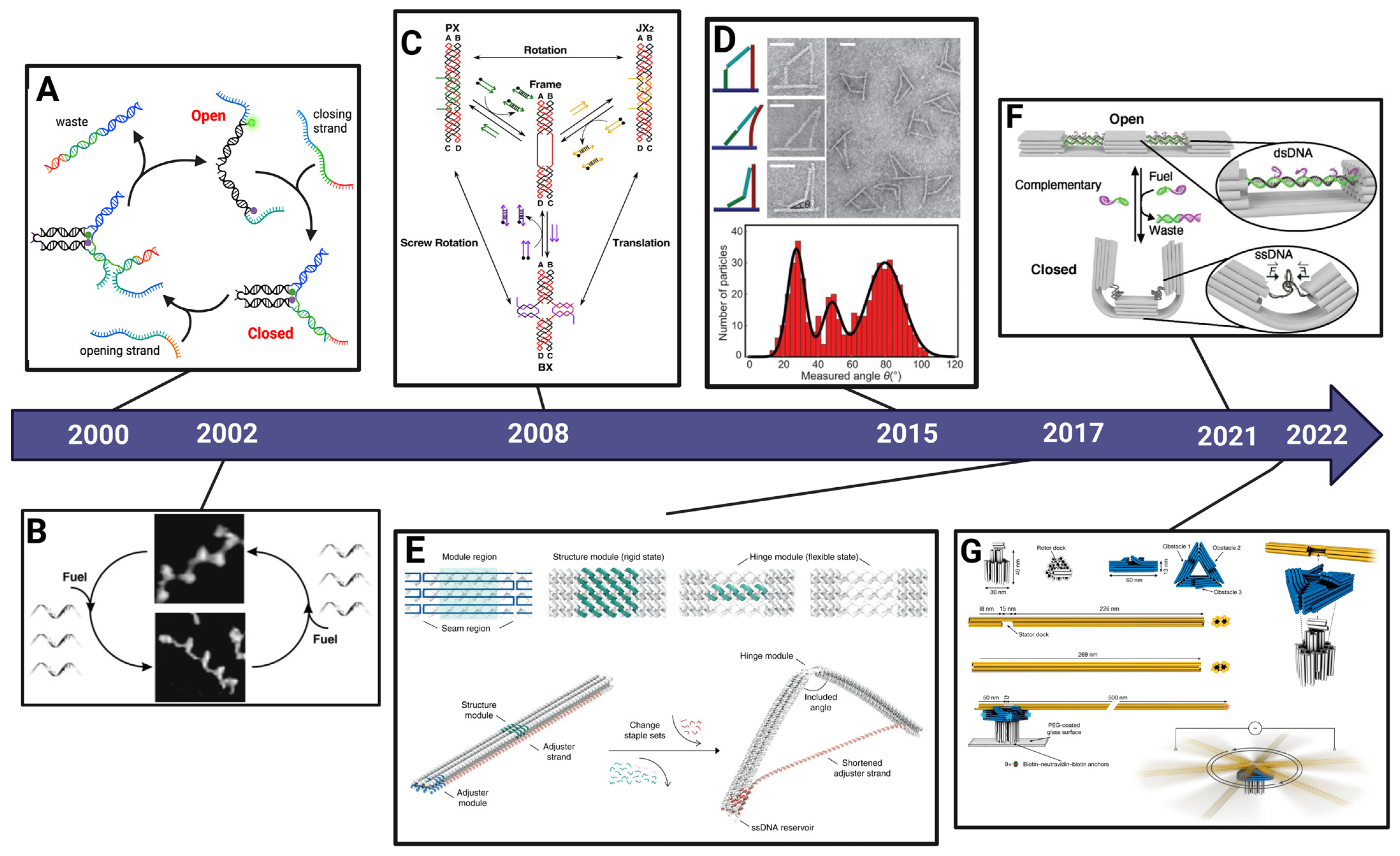
The field of structural DNA nanotechnology was initiated decades ago with Ned Seeman’s idea to build synthetic lattice structures from multi-arm DNA junctions [11]. The concept of making DNA nanodevices dynamic, or responsive to some external input, was also pioneered by Seeman and co-workers [12], and has become a major area of research and development [3]. Figure 1 illustrates several examples of nanomechanical DNA devices, highlighting their progression over multiple decades. The first demonstrations of reconfigurable DNA devices included systems wherein DNA strands or small structural motifs could be reconfigured via B-Z transition of DNA [12] or DNA strand displacement [13,14,15], and later, DNA structures that could be triggered into three states [16]. The development of scaffolded DNA origami [1] significantly advanced the geometric design space for DNA nanostructures, which also led to corresponding advances in complexity and functionality of nanomechanical DNA devices, including containers with controlled opening [17], nanoactuators with reversibly reconfigurable structural elements [18], and dynamic structures exhibiting multiple stable states [19] or photoactivated shape changes [20]. Other recent examples have leveraged the ability to tune mechanical properties of components to create devices with various deformed states for polymorphic designs [21], or DNA origami, in which conversions between double- and single-stranded DNA cause shape changes [22]. These examples highlight the emergence of nanomechanical design in DNA nanotechnology; more extensive overviews of nanomechanical DNA devices are available in recent reviews [10,23,24].
Generally, DNA nanotechnology studies rely on a variety of principles from multiple disciplines in science and engineering, thus making it an excellent field for interdisciplinary education modules. Useful general introductions to structural DNA nanotechnology can be found in a number of review or research articles [26,27,28,29]. Recent work has taken important steps to translate simpler DNA constructs into classroom experiments [30,31], introducing concepts such as conformational changes, DNA structural motifs, and nanostructure biostability. However, translating more complex DO into educational experiences has been challenging, due to the complexity of design, long time periods for experiments, and relatively high cost of materials and equipment. Hence, the study of complex DO devices has been limited mainly to research institutions in graduate-level laboratories with significant prior expertise and well-equipped laboratories. In an effort to lower this barrier, we recently presented classroom-friendly methods for the fabrication and analysis of DO structures [26]. These methods leverage the ability to fold DO rapidly at constant temperature [32] and the ability to fold DO with low-cost equipment [33]. Building on those advances, we developed an educational experiment module to demonstrate the basic methods and concepts for folding a simple static DO nanorod design [26]. The fabrication utilizes simple heated water baths, consisting of water-filled beakers heated on hot plates, to carry out folding on the time scale of ~15 min. The analysis consists of an evaluation of folding via agarose gel electrophoresis that can be carried out within ~40 min on a cost-effective MiniOne gel electrophoresis system designed for classroom implementation. Including sample and experiment prep time, the module can be completed in ~90–120 min, or in ~60 min if experiment prep work is done beforehand.
Here, we continue advancing the educational translation of DO nanotechnology with a focus on introducing the mechanical design of DNA nanostructures [34]. We present the optimized fabrication and analysis of a DO ‘compliant hinge joint’ (CHJ) structure [35] that can be folded into multiple configurations with varying degrees of mechanical deformation. The different configurations are achieved by substituting a small subset of the constituent DNA strands, leveraging the concept of modular design. We demonstrate that the different configurations result in different mobilities in gel electrophoresis using classroom-ready gel equipment. As with the previous module [26], the experiments can be completed within a ~120 min laboratory period including sample and experiment prep or within a ~60 min classroom period (~15–20 min folding and ~40–45 min gel electrophoresis) if experiment and sample prep is done beforehand. Additionally, to expand upon these education experiment modules and introduce the interdisciplinary integration of DNA nanotechnology and mechanical design to science and engineering classrooms, we also propose two mechanical models based on beam-bending that relate the nanostructure properties to the resulting deforming structure.
2. Methods
2.1. Fabrication of the DNA Origami Compliant Hinge Joint
The CHJ structure design was presented in a previous study [35]. The structure was designed in caDNAno [36] and is folded using a 7560 nucleotide (nt)-long single-stranded DNA (ssDNA) scaffold [2] and ~160 short ssDNA staple strands of ~20–50 nt purchased from a commercial vendor (IDT, Coralville, IA, Supplementary). The scaffold was prepared in our laboratory as previously described [27]. Folding reactions contained a 20 nM scaffold and 200 nM of each staple strand in a ddH2O solution containing 5 mM Tris, 5 mM NaCl, 1 mM EDTA, and 20 mM MgCl2 at pH 8.0.
For control fabrication experiments, folding reactions were carried out as previously described [35]. CHJ folding reactions were subjected to thermal annealing in a thermal cycler (Bio-Rad T100, Hercules, CA, USA) over a 2.5-day ramp starting at 1 h/°C from 65 to 61 °C, followed by an annealing phase at 2 h/°C from 60 to 40 °C and a cooling phase at 30 min/°C from 39 to 4 °C.
For the classroom setting, folding reactions were carried out similar to our previous work [26]. Hot plates (Thermo Scientific Cimarec Basic, Waltham, MA, USA) were used as the heating element, replacing the thermal cycler, to heat 1000 mL beakers filled with 900 mL of tap water and the hot plate at the maximum temperature setting until the water reached the target temperature (monitored with a thermometer placed in the water bath). One water bath was heated to 65 °C for the melting phase and the other to 52 (±1) °C for the folding phase of fabrication. Once the target temperature was reached, the beaker was placed in a Styrofoam bucket. Then, the sample tubes were successively incubated in the 65 °C beaker for 5 min and transferred to the 52 °C beaker for 10 min with floating foam tube racks (Avantor, Radnor Township, PA, USA). Throughout the folding process, the temperature was monitored with a thermometer placed in each water bath, and the beaker was placed back onto the hot plate to maintain the temperature as needed. After the 10 min incubation in the annealing water bath, the sample tubes were quenched in an ice bucket for 5 min. This process is slightly altered from our previously presented approach [26]. Here, we used a larger volume of water (900 mL instead of 500 mL) and the Styrofoam cooler to slow down cooling of the water bath, whereas in our prior study, we used 500 mL and placed the annealing beaker on a tabletop on a piece of cardboard for insulation. Both methods are suitable, with the latter requiring closer monitoring of temperature.
2.2. Analysis of CHJ by Agarose Gel Electrophoresis
Agarose gel electrophoresis was used to evaluate DO folding and structure conformation. Folded DO structures typically run faster than the ssDNA scaffold due to the compact nature of the folded structure. For initial experiments carried out with laboratory gel electrophoresis equipment, we followed typical DO gel electrophoresis protocols as previously described [27]. Then, 15 μL of folded CHJ solution was mixed with 3 μL of 6× blue loading dye (New England BioLabs, Ipswich, MA, USA). The folding reaction and loading dye mixture was then pipetted into wells of a 2% agarose gel containing 0.5× TBE (Tris/Borate/EDTA buffer of 45 mM boric acid, 45 mM of Tris(hydroxymethyl)aminomethane base, and 1 mM of ethylenedinitrilo-tetraacetic acid with 11 mM of MgCl2 and 0.5 μg mL−1 of ethidium bromide. The gel was submerged in a running buffer containing 0.5× TBE and 11 mM of MgCl2, and the gel was run at 90 V for ~90 min. Gels were then imaged in an Analytik Jena UVP GelStudio touch 12 MP imaging station.
For the classroom implementation, gels were run on a MiniOne gel electrophoresis system. In the MiniOne system, 9 μL of folded CHJ solution was mixed with 2 μL of orange loading dye (1000 mg Ficoll/10 mL ddH2O (Sigma-Aldrich, St. Louis, MO, USA) and 10 mg orange G (Sigma-Aldrich) and loaded into the wells of a 1% agarose gel containing 0.5× TBE, 6 mM of MgCl2, and 0.5 μg mL−1 of SYBR Safe (Thermo Fisher Scientific, Hercules, CA, USA). Gels were run at 42 V for 40 min (unless otherwise noted) in an adjusted running buffer containing 0.17× TBE with 2 mM of MgCl2 to accommodate the MiniOne system resistance range (based on guidance from MiniOne® (San Diego, CA, USA) Electrophoresis System Instructional Manual, see Supplement Table S2). Gels were visualized with the LED-illuminated blue light that is directly built into the MiniOne system, and images were taken with a cell phone camera. Note that here, we used SYBR Safe gel stain, but we previously showed that Gel Green is also suitable for MiniOne gel electrophoresis analysis of DO structures [28].
2.3. Imaging of DNA Origami via Transmission Electron Microscopy
Bands corresponding to well-folded CHJ structures were directly cut under UV illumination, and structures were filtered from gel bands by centrifuging at 10,000 g for 10 min in freeze-and-squeeze gel-extraction spin columns (BioRad, Hercules, CA, USA). Prior to deposition on transmission electron microscopy (TEM) grids, the final MgCl2 concentration of the gel-extracted solution sample was adjusted to 10 mM. TEM grid preparation was performed as previously described [27,35]. Then, 4 uL of sample volume was deposited on Formvar-coated copper TEM grids, stabilized with evaporated carbon film (Ted Pella; Redding, CA, USA). The sample was incubated on the grid for 4 min, wicked away with filter paper, and then stained by applying 10 μL of 2% uranyl formate (SPI, West Chester, PA, USA) solution containing 25 mM NaOH twice, while wicking away the stain with filter paper after 1 s each time. Samples were left to dry for at least 20 min before imaging. TEM imaging was carried out at the OSU Campus Microscopy and Imaging Facility on an FEI Tecnai G2 Spirit TEM at an acceleration voltage of 80 kV.
2.4. Simulation of DNA Origami CHJ
We selected one version of the CHJ design as an example for visualizing the molecular details of the nanostructure via simulation. The caDNAno design json file was imported directly to the website-based toolbox oxView [37,38]. The structure was first manipulated manually with rigid-body translations to position components close to the target geometry and then relaxed subsequentially using built-in rigid-body, Monte Carlo, and molecular dynamics relaxation algorithms with default settings to ensure reasonable physical DNA backbone distances for neighboring nucleotides. The simulation was then conducted using the real-time oxServer with 106 simulation steps. The structure was finally rendered by VMD. We selected the last configuration from the simulatioin for the purpose of visualizing a molecular depiction of the CHJ structure.
3. Results
3.1. The Compliant Hinge Joint Design
The DO design process for nanomechanical DNA structures generally consists of (1) determining a desired geometry based on the intended function; (2) dividing the target geometry into sub-components (if necessary); (3) assigning a cross-section to each sub-component (or assigning ssDNA component composition); (4) determining scaffold routing to satisfy the desired geometry and component design; (5) determining the staple routing. Since the design process for nanomechanical devices requires significant expertise, here, we bypass the design process by using a previously established compliant DO structure. As a brief note, over the last 15 years, the most widely used design tool is caDNAno [36]. More recently, a number of additional design tools have been developed with varying levels of automation [39,40,41,42,43]. An overview of design tools is provided in a recent review article [44], and many tutorials can be found online (see Table S3 in Supplemental Information), if educators wish to include lessons on DO design.
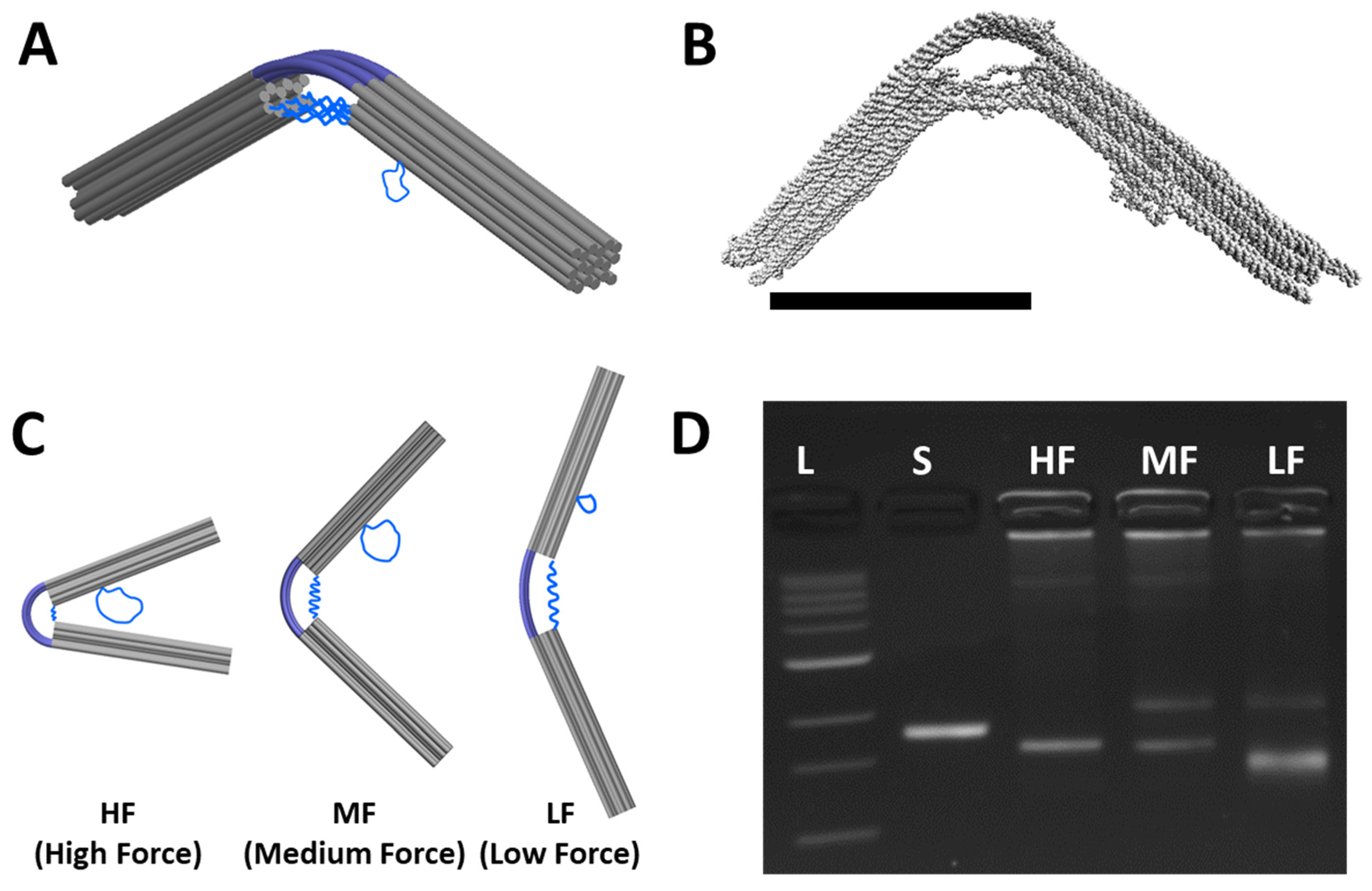
The CHJ was developed by Zhou et al. [35] as a compliant nanostructure similar to a torsional spring with tunable equilibrium angle and flexibility. The design is comprised of two arms that are ~55 nm long from the vertex to ends of arms and made up of 18-helix bundles each organized in a 6 × 3 hexagonal lattice cross-section (Figure 2A). The arms are connected at the joint end by six flexible ssDNA linkers that span across the joint connecting the bottom layer of helices on the two arms, and the top layer of six double-stranded DNA (dsDNA) helices connects the two arms directly across the joint. The six-helix dsDNA layer deforms in bending due to forces generated by the entropic elasticity of the ssDNA linkers. Hence, the top layer is the compliant component that deforms to modify the overall structure geometry. Here, the ssDNA linkers function as entropic springs that apply forces causing the dsDNA compliant layer to bend. The geometry of loading and the anisotropic bending stiffness of the six-helix layer ensures that bending occurs primarily in a single direction, leading to a well-defined joint angle (deformations previously studied in detail by Shi et al. [45]). The two outer arms are stiff and remain basically straight [35]. The CHJ was originally designed in caDNAno [36] with additional details provided by Zhou et al. [35]. Figure 2B shows the CHJ structure configuration predicted from oxDNA simulations conducted in the oxView web interface [37,38] and visualized using VMD software (version 1.9.4a53) [46].
The deformation of the compliant joint, and hence the overall conformation of the CHJ, can be engineered by modifying the length of the ssDNA linker (Figure 2C). Shorter ssDNA linkers will generate a larger force, inducing stronger bending of the compliant joint. The CHJ design allows for easy tuning of the hinge configuration by introducing a scaffold reservoir near the joint (blue loops protruding from right arm in Figure 2C), so the length of the linkers can be easily adjusted by substituting a subset of staples near the joint that shift scaffold length between the reservoir and linkers. We focus here on three different configurations: high force (HF), medium force (MF), and low force (LF).
Figure 2D shows the three configurations of the CHJ analyzed by gel electrophoresis, demonstrating a small shift between the HF and MF configurations and a larger shift between the MF and LF configurations. For all the structures, we observed some aggregation, indicated by structures stuck in the well; for MF and LF structures, we observed a clear slower running band, which is likely indicative of a dimer population. We focused the rest of our analysis on the fastest running bands, which are the well-folded DO structures as confirmed by TEM images (Supporting Figure S2).
3.2. Folding the CHJ with Classroom-Friendly Protocols
The previous folding was carried out using laboratory thermocyclers, which are not practical for use in most classrooms. Enabling folding of DO in a science or engineering class or lab requires two key steps: (1) identifying a suitably short-duration and constant-temperature annealing protocol, and (2) ensuring that the protocol can be carried out with low-cost equipment (i.e., hot plates).
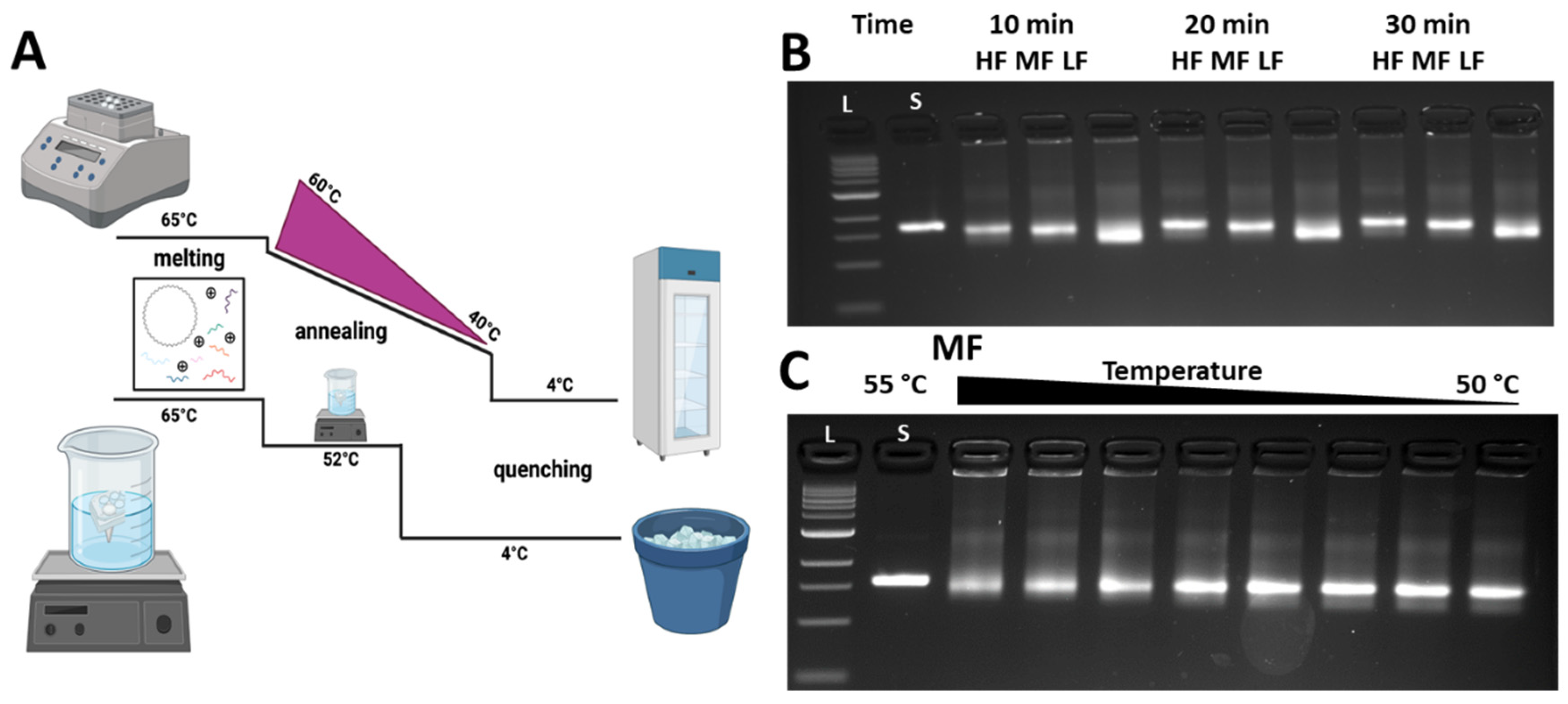
Standard folding procedures include annealing for long times over many precisely controlled temperatures, which is why a thermocycler is typically used. However, previous work has shown that DO structures can be folded at constant temperature over shorter periods of time [32], which is conducive to folding with low-cost equipment in a reasonable classroom period time. Figure 3A shows the thermal ramp comparison between laboratory (top curve) and classroom (bottom curve) folding approaches. Both consist of three phases: melting, annealing, and quenching; however, for the classroom approach, we could achieve constant temperature annealing over short times by using a heating element consisting of a water bath heated by a hot plate. To first explore short annealing times, we tested the three different versions (HF, MF, and LF) with different annealing times of 10 min, 20 min, and 30 min at a constant annealing temperature of 52 °C in the thermal cycler. We previously showed that 52 °C works well for the constant temperature annealing of many different DO structures [33]. All folding reactions still included a melting phase of 5 min at 65 °C and a quenching phase of 5 min at 4 °C. After folding, structures were evaluated via agarose gel electrophoresis (with the research laboratory electrophoresis setup). Figure 3B shows the gel results for the three versions of the CHJ, illustrating a similar pattern of gel shifts to the control structures (Figure 2D). For all annealing times, MF ran slightly faster than HF, and LF exhibited a larger shift with respect to MF. TEM for all versions and annealing times confirmed well-folded structures (Supporting Figure S2). These results demonstrated that the 10 min annealing time is suitable for illustrating the gel shifts that are indicative of distinct deformed configurations. Interestingly, we also found that there is much less aggregation in the shorter folding time in comparison with the 2.5-day protocol. This is consistent with prior work showing that shorter annealing times may help avoid aggregate formation for DO structures [32].
Since we aimed to fold the CHJ using low-cost equipment, which would lead to less precise control over the folding temperatures, we also tested if the folding yield was sensitive to the exact annealing temperature. We conducted a screen of constant annealing temperatures from 55 °C to 50 °C in a thermal cycler with the same folding protocol (5 min melting at 65 °C, 10 min at set annealing temperature, 5 min quenching at 4 °C). Figure 4C shows the results of this temperature screen for MF (LF, HF shown in Supplement Figure S3). For all annealing temperatures, the folded structure bands exhibited a similar mobility to the previously tested structures, with proper folding confirmed by TEM. These results indicate that the folding quality is mostly insensitive to annealing temperature over the range of 50–55 °C. That said, for higher temperatures in this range, we observed that the yields were slightly lower, as indicated by a more smeared structure band and some intensity in the wells. We concluded that the CHJ folding can be effectively carried out with precise control over temperature (i.e., only needing to control within a few °C). We chose to move forward with a desired annealing temperature range of 52 ± 1 °C.
We determined that this level of temperature control can be easily achieved with hot plate heating by placing and removing the beaker water bath from the hot plate. We found that the cooling rate of the beaker water bath (1 L beaker with 900 mL of water) is relatively low if the beaker is covered by aluminum foil and placed in a Styrofoam container for insulation when removed from the hot plate (~1 deg drop in 5 min). Alternatively, simpler insulation methods are also suitable, such as simply placing the beaker on a piece of cardboard on a table (as we previously showed [26]), but with a slightly faster cooling rate, requiring more careful monitoring. We tested the hot-plate folding approach for the three different CHJ versions. Supporting Figure S4 shows structures folded using the classroom folding protocol to structures folded in a thermocycler using laboratory gel electrophoresis, confirming that hot-plate folding leads to well-folded CHJ structures.
3.3. Analysis of the CHJ with Classroom Gel Electrophoresis
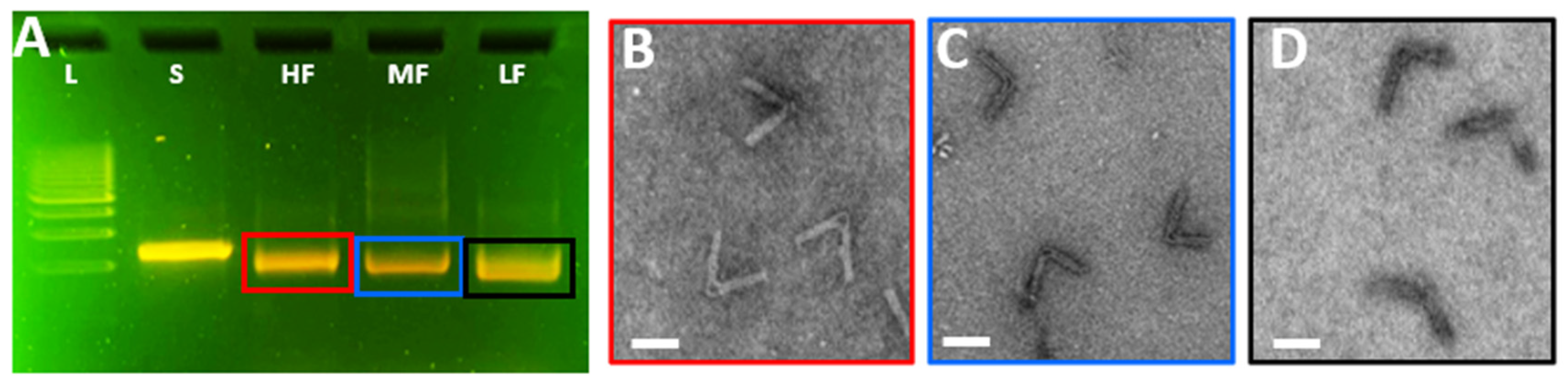
In addition to keeping the hot-plate folding step within a ~20 min duration, we also aimed to develop a classroom-ready approach for students to evaluate the folding and conformation of the CHJ structures. Typically, imaging methods such as TEM or AFM imaging are needed to assay nanostructure conformations; however, we previously demonstrated that the distinct conformations lead to varying mobilities in agarose gel electrophoresis (Figure 2D). In prior work, we established gel electrophoresis protocols [26] for examining DO structures in the classroom using the MiniOne gel electrophoresis system, which we leveraged here to analyze the three versions of the CHJ made with the hot-plate folding approach. As illustrated in Figure 4A, we observed a similar pattern of gel shifts between the HF, MF, and LF after running the gel for 40 min in the MiniOne System. To further confirm that the structures remain well-folded in the MiniOne gel system, we extracted the bands from the gel and then imaged the MiniOne gel-purified structures. TEM images (color-coded in Figure 4B–D) confirmed the well-folded structure for all three hinge configurations.
3.4. Mechanical Modeling of the Compliant Hinge Joint Angles
To guide the design of the CHJ structures and similar compliant hinge joints, we previously developed mechanical models that describe the structure deformation that results from the entropic force of the ssDNA linkers, causing bending of the joint [35,47]. In our previous work, we modeled the large bending deflection of the six-helix layer using Euler–Bernoulli beam theory [48]. These models, however, require the use of differential equations. Here, we aimed to develop simpler models that are more readily relatable to basic undergraduate-level engineering mechanics. We present two models to quantify the CHJ deformation and compare them with experiment data [35] (see Supplemental Materials for angle measurement tutorial).
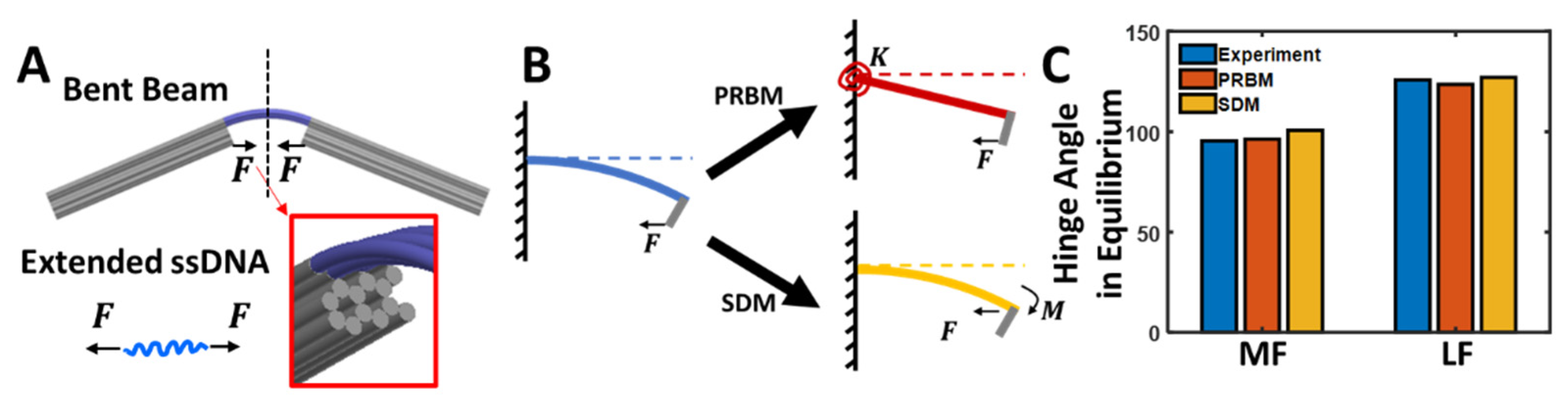
Given the high bending stiffness of the two arm extensions of the CHJ, we assumed that they are rigid, maintaining a straight configuration, so the angle is fully described by the bending of the six-helix layer, which has a lower bending stiffness. Here, we modeled the six-helix layer as a beam whose cross-section contains six helices (each helix being modeled as a circular shape) connected in the appropriate single-layer honeycomb cross-section (Figure 5A).
Bending of the six-helix layer is caused by the entropic force of the ssDNA linkers. As the six-helix layer bends, the end-to-end distance of the ssDNA linkers changes, thereby reducing the entropic force. In equilibrium, the entropic force generated by the ssDNA linkers in a particular configuration is balanced by the resistance force caused by the bending strain energy in the six-helix layer. To model the force from the ssDNA linker strands, we regard them as non-linear springs whose force-extension behavior is described by the Marko–Siggia approximation to the worm-like-chain (WLC) [49]:
where is the Bolzman factor, is the absolute temperature, is the ssDNA persistence length, is the end-to-end distance of the ssDNA linkers, and is the ssDNA contour length, which is a parameter that varies for different versions of the CHJ. The WLC is a model that is often used to describe the nonlinear force-extension behavior of biopolymers. All six ssDNA linkers that span the joint connecting the bottom layer of the 18-helix bundle arms apply a force. Due to the hexagonal lattice structure [2], the end-to-end distance of the three upper ssDNA springs of the bottom layer are not the same length as the three lower ssDNA springs in the bottom layer if the hinge angle is not 180°. To accommodate this spatial difference, the upper three linkers have the additional length of ssDNA (Table 1), while the lower three helices have 10 extra dsDNA base pairs (~3.4 nm). The total force from these six ssDNA strands would be as follows:
As previously noted, the force generated by these ssDNA linkers causes bending of the six-helix layer to deform the structure into a particular joint angle. Here, we proposed two simple models to describe the bending of the six-helix layer: (1) a pseudo-rigid-body model (PRBM) [35,50] and (2) a small deflection model (SDM) [51] (Figure 5B). We used these models to predict the deformation of the MF and LF versions; we do not predict the HF, because the zero-length of three of the ssDNA springs makes it challenging to calculate forces for those springs. However, a simple geometric approach also allows reasonable prediction of the HF joint angle (see details in Supporting Information Figure S7). Below, we first introduce the models and then discuss the results of their application to the CHJ.
3.5. Pseudo-Rigid-Body Model
Pseudo-rigid-body (PRB) models are used to model the deflection of flexible members using structures comprised of rigid elements connected by joints and springs to provide equivalent force-deflection characteristics to the real structure [50,52,53]; we have previously demonstrated the application of PRB models to deformable DNA origami structures [47]. Here, the six-helix layer that bends to form the joint angle can be considered as a flexible beam in a compliant DO structure. Following a PRB approach, we modeled the beam as a combination of a linear torsional spring and ‘L-shape’ solid bar (Figure 5B). The torsional stiffness of the spring in this PRB model of the compliant joint is as follows:
where is the original beam stiffness, is the half beam length, and is the correction factor.
Then, the force from the beam would be
where T is the torque on the torsional spring, is the vertical displacement of force at the tip, and is the hinge angle. Here, both and are explicitly dependent on the length of ssDNA linker (see detailed configuration in Supplement Figure S6).
Finally, when the hinges are in the equilibrium states, the force from ssDNA is equal to the force from the hinge:
This is a nonlinear algebraic equation dependent on the end-to-end distance of the ssDNA springs, , and it can be solved by a numerical solver such as ‘fsolve’ in MATLAB to find a solution with an appropriate initial guess.
3.6. Small Deflection Model
Using the small deflection model (SDM), we assumed that dsDNA linkers are made of two symmetric cantilever beams with small deflections. As shown in Figure 5B, the force provided from the ssDNA linker results in a force and an additional moment at the tip of the cantilever beam model. The force would tend to cause direct axial compression in the straight beam configuration but could increase the bending moment as the beam deforms. However, since this model assumes small deflection and any axial compression is likely small and does not contribute to the joint angle, we ignore the direct effect of the force. Therefore, we only consider the bending moment , which causes a deflection angle in the beam of
Note that the moment is a function of , because the force, F, is a function of (i.e., linker end-to-end distance depends on joint angle). In the small deflection configuration, it can be further expressed as
where the is the beam offset (length of gray bar next to beam in Figure 5B).
Meanwhile, the amount of force can be expressed by WLC model with replacement of variable from to by using the following trigonometric expression:
Again, we can use a numerical solver (e.g., MATLAB ‘fsolve’) to find the solution of , and the hinge angle can be determined as follows:
3.7. Predicting the CHJ Joint Angles
As shown in Figure 5C, both PRBM and SDM have a good agreement with the experimental data [35] (we provide a step-by-step tutorial in the Supporting Information in Figure S8 and Table S5 to show students how to determine the CHJ angle from experimental data) with a maximum relative error of 5.5%. Additionally, the force in equilibrium can be subsequently determined by directly evaluating with the given hinge angle. For MF, the force in balance is 12.3 pN from PRBM and 14.8 pN from SDM. For LF, it is 9.3 pN in PRBM and 9.9 pN in SDM.
The HF condition was not reported in these models, since the lower three ssDNA strands do not exist (0 bases). Therefore, it is infeasible to use the WLC model to determine the force. However, the angle in equilibrium can be determined geometrically by assuming 0 extensions, i.e., the ends of two L-shapes are touched (see Supplement Figure S7). The angle result from this calculation gives 60°, which agrees well with experimental results (61°).
4. Discussion
Here, we demonstrated the ability to fold a series of compliant DO structures and analyze their conformations via agarose gel electrophoresis with the use of low-cost portable equipment that is well-suited for classroom implementation. The folding can be carried out in ~20 min, and the gel electrophoresis can be carried out in ~40 min. Including sample and experiment preparation time, the full module can be completed in a 2 h laboratory period, or if prep work is done ahead of time, the folding and gel analysis can be carried out within ~1 h. The cost of the materials needed for these educational experiments is relatively low. Based on the typical costs of DNA staple and scaffold strands (see details of cost estimates here: [33]), we estimate the costs for the material required for five lab groups to be ~$1–5. Hence, an educator could order materials for ~$10–100 to cover the materials for a full semester or year for a typical sized class. Costs could be slightly higher, as materials often have to be purchased in some minimum amount. In the future, we envision that kits could be produced to provide all the required materials and reagents in amounts appropriate for one class for one semester.
The major cost savings is in avoiding the need for expensive equipment. We focused on demonstrating these modules with equipment that is readily available in many science classrooms or is relatively low-cost. It is likely possible to further simplify the educational experiments or adapt them based on available equipment. For example, a microwave could be used to heat a water beaker and then placed in insulation once at the correct temperature. The folding could also likely be carried out with insulation to achieve slow cooling, instead of a constant temperature. However, since annealing rates may vary based on the insulation setup, maintaining a constant temperature (52 ± 1 °C) would likely lead to more consistent results. One opportunity to enhance the modules could be to expose students to imaging methods for direct visualization. Here, we visualized structures by TEM, which is not practical for classroom implementation. However, images provided here (including Supporting Information) could be provided to students to give structural context for the observed changes in gel mobility. Another option for direct visualization is atomic force microscopy (AFM), which may be feasible for classroom implementation given some possible low-cost custom-built options [54].
This experiment module could be presented as a stand-alone experience or in combination with our previously established experiment module focused on the folding of a static DO nanostructure [26]. In either case, from the fabrication and analysis, students can learn basic biology skills such as pipetting, mixing reactions, DNA annealing, agarose gel electrophoresis, and UV imaging. Students are also exposed to DNA origami nanotechnology concepts, which can connect to and reinforce mechanical engineering concepts through mechanical models of structure deformation. We propose a set of learning outcomes in Supporting Table S4 that could be adopted, edited, or added to for future use by educators implementing the module into a classroom.
Furthermore, this work focuses on introducing the strong connection between compliant DO structures and mechanical design. To highlight this connection, we implemented pseudo-rigid-body models and small-deformation bending models to describe the deformed state of the compliant hinge. Importantly, these approaches agree reasonably with the experimental results while relying on, reinforcing, and providing new application context for undergraduate-level engineering mechanics. The force balance was employed to build up the connection between the ssDNA linkers and the bending of the compliant joint. Therefore, after determining the hinge angle, the corresponding force could also be determined, i.e., by using the hinge angle to determine the ssDNA extension and then applying the WLC to determine the force. Students could further be introduced to other efforts to quantify and model the bending stiffness of DNA origami structures [55], and we also included a sample bending stiffness comparison for different configurations (Supplementary Figure S9). More broadly, this module can serve to introduce the concept and value of inter-disciplinary research, through which students can experience connections between multiple fields, especially biology, nanotechnology, and mechanical engineering.
This work provides the first classroom-friendly characterization of a deformable (i.e., reconfigured by force application) DNA origami structure, where in this case, the force application occurs during folding to achieve the target shape. This work bridges mechanics and DNA nanotechnology to provide an immersive, hands-on interdisciplinary learning environment. The utilization of inexpensive and accessible lab equipment allows middle school, high school, and undergraduate students the opportunity to learn about DNA origami in a mechanical sense while gaining wet-lab skills. Furthermore, there are multiple opportunities for educators to dive deeper into DO nanotechnology, especially on the front-end design, in computational modeling or more advanced characterizations or actuation. These experiments could be implemented into research-intensive universities and primarily undergraduate institutions that have biological engineering, biology, biochemistry, mechanical engineering, and chemical engineering departments, where we believe they could be fit into courses incorporating DNA nanotechnology, biophysical interactions, or biomechanical curricula. These protocols would be straightforward for current research labs focused on DNA nanotechnology to implement in classes taught by the principal investigators. We provide a step-by-step overview of the experiment workflow to guide classroom implementation (Supporting Information). In the future, materials and reagents could be provided in kits to make implementation easier. We envision that the wet-lab experience and application of mechanical modeling that this module provides can expose students to STEM-related careers and research practices and thereby potentially stimulate interest in higher education.
Supplementary Materials
The following information can be downloaded at: https://0-www-mdpi-com.brum.beds.ac.uk/article/10.3390/app13053208/s1, Figure S1: Typical TEM images for laboratory folded CHJ structures; Figure S2: Typical TEM images for rapidly folded CHJ structures; Figure S3: Temperature screen of CHJ; Figure S4: Gel electrophoresis analysis of rapidly folded CHJ structures; Figure S5: Force-extension behavior of ssDNA springs; Figure S6: Parameters used for PRBM; Figure S7: Geometric estimation of HF configuration; Table S1: Basic parameters used for analytical models; Table S2: resistance of ionic liquids; Table S3: DNA nanotechnology design software tools; Table S4: Table of sample learning objectives; Figure S8: Workfolow for experimental analysis of hinge angle distributions; Table S5: Sample code for generating angular distributions; Figure S9: A general comparison of bending stiffness with different number of layers and lattice type, hexagonal lattice and square lattice; Figure S10: Full size gel electrophoresis images; Overview of suggested classroom protocol with required equipment and expected results; Sample questions for laboratory assignment focused on mechanical modeling aspects.
Author Contributions
C.E.C. and M.W.H. conceptualized the project, guided the execution of experiments and modeling, and supervised the research team. Y.W. and A.K. led the execution of experiments including folding, gel electrophoresis, and electron microscopy. Y.W. led the mechanical modeling, including the Matlab code that was written for implementation. L.D.R., P.E.B. and N.W. supported the experimental work, with L.D.R. and N.W. especially focusing on the classroom implementation of folding and gel electrophoresis, and P.E.B. focusing on electron microscopy and laboratory gel electrophoresis. A.K. and Y.W. led the initial drafting with all authors providing editing and feedback. C.E.C. and M.W.H. aquired the funding for this work All authors have read and agreed to the published version of the manuscript.
Funding
This work was supported by NSF grants #1916740, #1921881, and #1351159 to CEC and by start-up funding provided to MWH by Otterbein University. We would also like to acknowledge the OSU Pelotonia fellowship program for funding PEB. Transmission electron microscopy images were acquired at the OSU Campus Microscopy and Imaging Facility, which is supported in part by grant number P30 CA016058, National Cancer Institute, Bethesda, MD, USA.
Institutional Review Board Statement
Not applicable.
Informed Consent Statement
Not applicable.
Data Availability Statement
The majority of data used in this study are either presented in the manuscript or in the supporting information. The caDNAno designs for the CHJ structures are deposited at nanobase.org (https://nanobase.org/structure/197, accessed on 24 January 2023). Representative TEM images and angular conformation data are provided in the supporting information. Additional TEM images and angular measurements are available upon request for students to carry out more extensive conformation analysis.
Conflicts of Interest
The authors declare no conflict of interest.
References
- Rothemund, P.W.K. Folding DNA to create nanoscale shapes and patterns. Nature 2006, 440, 297–302. [Google Scholar] [CrossRef] [PubMed] [Green Version]
- Douglas, S.M.; Dietz, H.; Liedl, T.; Högberg, B.; Graf, F.; Shih, W.M. Self-assembly of DNA into nanoscale three-dimensional shapes. Nature 2009, 459, 414–418. [Google Scholar] [CrossRef] [PubMed]
- Hong, F.; Zhang, F.; Liu, Y.; Yan, H. DNA Origami: Scaffolds for Creating Higher Order Structures. Chem. Rev. 2017, 117, 12584–12640. [Google Scholar] [CrossRef] [PubMed]
- Marras, A.E.; Zhou, L.; Su, H.J.; Castro, C.E. Programmable motion of DNA origami mechanisms. Proc. Natl. Acad. Sci. USA 2015, 112, 713–718. [Google Scholar] [CrossRef] [PubMed] [Green Version]
- Shin, J.-S.; Pierce, N.A. A Synthetic DNA Walker for Molecular Transport. J. Am. Chem. Soc. 2004, 126, 10834–10835. [Google Scholar] [CrossRef] [PubMed] [Green Version]
- Fan, D.; Wang, J.; Wang, E.; Dong, S. Propelling DNA Computing with Materials’ Power: Recent Advancements in Innovative DNA Logic Computing Systems and Smart Bio-Applications. Adv. Sci. 2020, 7, 2001766. [Google Scholar] [CrossRef] [PubMed]
- Li, R.; Chen, H.; Choi, J.H. Auxetic Two-Dimensional Nanostructures from DNA. Angew. Chem. Int. Ed. 2021, 60, 7165–7173. [Google Scholar] [CrossRef]
- Wang, S.; Zhou, Z.; Ma, N.; Yang, S.; Li, K.; Teng, C.; Ke, Y.; Tian, Y. DNA origami-enabled biosensors. Sensors 2020, 20, 6899. [Google Scholar] [CrossRef] [PubMed]
- Udomprasert, A.; Kangsamaksin, T. DNA origami applications in cancer therapy. Cancer Sci. 2017, 108, 1535–1543. [Google Scholar] [CrossRef] [PubMed] [Green Version]
- Ji, J.; Karna, D.; Mao, H. DNA origami nano-mechanics. Chem. Soc. Rev. 2021, 50, 11966–11978. [Google Scholar] [CrossRef] [PubMed]
- Seeman, N.C. Nucleic acid junctions and lattices. J. Theor. Biol. 1982, 99, 237–247. [Google Scholar] [CrossRef] [PubMed]
- Mao, C.; Sun, W.; Shen, Z.; Seeman, N.C. A nanomechanical device based on the B–Z transition of DNA. Nature 1999, 397, 144–146. [Google Scholar] [CrossRef] [PubMed]
- Yurke, B.; Turber, A.J.; Mills, A.P., Jr.; Simmel, F.C.; Neumann, J.L. A DNA-fuelled molecular machine made of DNA. Nature 2000, 406, 605–608. [Google Scholar] [CrossRef] [PubMed]
- Yan, H.; Zhang, X.; Shen, Z.; Seeman, N.C. A robust DNA mechanical device controlled by hybridization topology. Nature 2002, 415, 62–65. [Google Scholar] [CrossRef] [PubMed]
- Niemeyer, C.M.; Adler, M. Nanomechanical Devices Based on DNA. Angew. Chem. Int. Ed. 2002, 41, 3779–3783. [Google Scholar] [CrossRef]
- Chakraborty, B.; Sha, R.; Seeman, N.C. A DNA-based nanomechanical device with three robust states. Proc. Natl. Acad. Sci. USA 2008, 105, 17245–17249. [Google Scholar] [CrossRef] [Green Version]
- Andersen, E.S.; Dong, M.; Nielsen, M.M.; Jahn, K.; Subramani, R.; Mamdouh, W.; Golas, M.M.; Sander, B.; Stark, H.; Oliveira, C.L.P.; et al. Self-assembly of a nanoscale DNA box with a controllable lid. Nature 2009, 459, 73–76. [Google Scholar] [CrossRef] [Green Version]
- Marini, M.; Piantanida, L.; Musetti, R.; Bek, A.; Dong, M.; Besenbacher, F.; Lazzarino, M.; Firrao, G. A Revertible, Autonomous, Self-Assembled DNA-Origami Nanoactuator. Nano Lett. 2011, 11, 5449–5454. [Google Scholar] [CrossRef]
- Zhou, L.; Marras, A.E.; Su, H.-J.; Castro, C.E. Direct Design of an Energy Landscape with Bistable DNA Origami Mechanisms. Nano Lett. 2015, 15, 1815–1821. [Google Scholar] [CrossRef]
- Willner, E.M.; Kamada, Y.; Suzuki, Y.; Emura, T.; Hidaka, K.; Dietz, H.; Sugiyama, H.; Endo, M. Single-Molecule Observation of the Photoregulated Conformational Dynamics of DNA Origami Nanoscissors. Angew. Chem. Int. Ed. 2017, 56, 15324–15328. [Google Scholar] [CrossRef]
- Lee, C.; Lee, J.Y.; Kim, D.-N. Polymorphic design of DNA origami structures through mechanical control of modular components. Nat. Commun. 2017, 8, 2067. [Google Scholar] [CrossRef] [Green Version]
- Gür, F.N.; Kempter, S.; Schueder, F.; Sikeler, C.; Urban, M.J.; Jungmann, R.; Nickels, P.C.; Liedl, T. Double- to Single-Strand Transition Induces Forces and Motion in DNA Origami Nanostructures. Adv. Mater. 2021, 33, 2101986. [Google Scholar] [CrossRef] [PubMed]
- DeLuca, M.; Shi, Z.; Castro, C.E.; Arya, G. Dynamic DNA nanotechnology: Toward functional nanoscale devices. Nanoscale Horiz. 2020, 5, 182–201. [Google Scholar] [CrossRef]
- Nummelin, S.; Shen, B.; Piskunen, P.; Liu, Q.; Kostiainen, M.A.; Linko, V. Robotic DNA Nanostructures. ACS Synth. Biol. 2020, 9, 1923–1940. [Google Scholar] [CrossRef] [PubMed]
- Pumm, A.-K.; Engelen, W.; Kopperger, E.; Isensee, J.; Vogt, M.; Kozina, V.; Kube, M.; Honemann, M.N.; Bertosin, E.; Langecker, M.; et al. A DNA origami rotary ratchet motor. Nature 2022, 607, 492–498. [Google Scholar] [CrossRef] [PubMed]
- Beshay, P.E.; Kucinic, A.; Wile, N.; Halley, P.; Rosiers, L.D.; Chowdhury, A.; Hall, J.L.; Castro, C.E.; Hudoba, M.W. Translating DNA origami Nanotechnology to Middle School, High School, and Undergraduate Laboratories. bioRxiv 2022. [Google Scholar] [CrossRef]
- Castro, C.E.; Kilchherr, F.; Kim, D.N.; Shiao, E.L.; Wauer, T.; Wortmann, P.; Bathe, M.; Dietz, H. A primer to scaffolded DNA origami. Nat. Methods 2011, 8, 221–229. [Google Scholar] [CrossRef]
- Seeman, N.C.; Sleiman, H.F. DNA nanotechnology. Nat. Rev. Mater. 2017, 3, 1–23. [Google Scholar] [CrossRef]
- Dey, S.; Fan, C.; Gothelf, K.V.; Li, J.; Lin, C.; Liu, L.; Liu, N.; Nijenhuis, M.A.D.; Saccà, B.; Simmel, F.C.; et al. DNA origami. Nat. Rev. Methods Primer 2021, 1, 1–24. [Google Scholar] [CrossRef]
- Abraham Punnoose, J.; Halvorsen, K.; Chandrasekaran, A.R. DNA Nanotechnology in the Undergraduate Laboratory: Analysis of Molecular Topology Using DNA Nanoswitches. J. Chem. Educ. 2020, 97, 1448–1453. [Google Scholar] [CrossRef]
- Chandrasekaran, A.R. DNA Nanotechnology in the Undergraduate Laboratory: Electrophoretic Analysis of DNA Nanostructure Biostability. J. Chem. Educ. 2023, 100, 316–320. [Google Scholar] [CrossRef]
- Sobczak, J.P.J.; Martin, T.G.; Gerling, T.; Dietz, H. Rapid folding of DNA into nanoscale shapes at constant temperature. Science 2012, 338, 1458–1461. [Google Scholar] [CrossRef] [PubMed]
- Halley, P.D.; Patton, R.A.; Chowdhury, A.; Byrd, J.C.; Castro, C.E. Low-cost, simple, and scalable self-assembly of DNA origami nanostructures. Nano Res. 2019, 12, 1207–1215. [Google Scholar] [CrossRef]
- Castro, C.E.; Su, H.J.; Marras, A.E.; Zhou, L.; Johnson, J. Mechanical design of DNA nanostructures. Nanoscale 2015, 7, 5913–5921. [Google Scholar] [CrossRef] [PubMed]
- Zhou, L.; Marras, A.E.; Su, H.J.; Castro, C.E. DNA origami compliant nanostructures with tunable mechanical properties. ACS Nano 2014, 8, 27–34. [Google Scholar] [CrossRef]
- Douglas, S.M.; Marblestone, A.H.; Teerapittayanon, S.; Vazquez, A.; Church, G.M.; Shih, W.M. Rapid prototyping of 3D DNA-origami shapes with caDNAno. Nucleic Acids Res. 2009, 37, 5001–5006. [Google Scholar] [CrossRef] [Green Version]
- Poppleton, E.; Bohlin, J.; Matthies, M.; Sharma, S.; Zhang, F.; Šulc, P. Design, optimization and analysis of large DNA and RNA nanostructures through interactive visualization, editing and molecular simulation. Nucleic Acids Res. 2020, 48, e72. [Google Scholar] [CrossRef]
- Bohlin, J.; Matthies, M.; Poppleton, E.; Procyk, J.; Mallya, A.; Yan, H.; Šulc, P. Design and simulation of DNA, RNA and hybrid protein–nucleic acid nanostructures with oxView. Nat. Protoc. 2022, 17, 1762–1788. [Google Scholar] [CrossRef]
- Veneziano, R.; Ratanalert, S.; Zhang, K.; Zhang, F.; Yan, H.; Chiu, W.; Bathe, M. Designer nanoscale DNA assemblies programmed from the top down. Science 2016, 352, 1534. [Google Scholar] [CrossRef] [Green Version]
- Benson, E.; Mohammed, A.; Gardell, J.; Masich, S.; Czeizler, E.; Orponen, P.; Högberg, B. DNA rendering of polyhedral meshes at the nanoscale. Nature 2015, 523, 441–444. [Google Scholar] [CrossRef] [Green Version]
- Jun, H.; Shepherd, T.R.; Zhang, K.; Bricker, W.P.; Li, S.; Chiu, W.; Bathe, M. Automated Sequence Design of 3D Polyhedral Wireframe DNA Origami with Honeycomb Edges. ACS Nano 2019, 13, 2083–2093. [Google Scholar] [CrossRef] [PubMed]
- Huang, C.M.; Kucinic, A.; Johnson, J.A.; Su, H.J.; Castro, C.E. Integrated computer-aided engineering and design for DNA assemblies. Nat. Mater. 2021, 20, 1264–1271. [Google Scholar] [CrossRef] [PubMed]
- Fu, D.; Pradeep Narayanan, R.; Prasad, A.; Zhang, F.; Williams, D.; Schreck, J.S.; Yan, H.; Reif, J. Automated design of 3D DNA origami with non-rasterized 2D curvature. Sci. Adv. 2022, 8, eade4455. [Google Scholar] [CrossRef] [PubMed]
- Glaser, M.; Deb, S.; Seier, F.; Agrawal, A.; Liedl, T.; Douglas, S.; Gupta, M.K.; Smith, D.M. The Art of Designing DNA Nanostructures with CAD Software. Molecules 2021, 26, 2287. [Google Scholar] [CrossRef]
- Shi, Z.; Castro, C.E.; Arya, G. Conformational Dynamics of Mechanically Compliant DNA Nanostructures from Coarse-Grained Molecular Dynamics Simulations. ACS Nano 2017, 11, 4617–4630. [Google Scholar] [CrossRef]
- Humphrey, W.; Dalke, A.; Schulten, K. VMD: Visual molecular dynamics. J. Mol. Graph. 1996, 14, 33–38. [Google Scholar] [CrossRef]
- Zhou, L.; Marras, A.E.; Castro, C.E.; Su, H.-J. Pseudorigid-Body Models of Compliant DNA Origami Mechanisms. J. Mech. Robot. 2016, 8, 051013. [Google Scholar] [CrossRef]
- Bauchau, O.A.; Craig, J.I. Euler-Bernoulli beam theory. In Structural Analysis; Bauchau, O.A., Craig, J.I., Eds.; Springer: Dordrecht, The Netherlands, 2009; pp. 173–221. [Google Scholar] [CrossRef]
- Marko, J.F.M.; Siggia, E.D.S. Bending and Twisting Elasticity of DNA. Macromolecules 1994, 27, 981–988. [Google Scholar] [CrossRef]
- Howell, L.L. Compliant Mechanisms. In Encyclopedia of Nanotechnology; Bhushan, B., Ed.; Springer: Dordrecht, The Netherlands, 2016; pp. 604–611. ISBN 978-94-017-9780-1. [Google Scholar]
- Hibbeler, R.C. Mechanics of Materials; Prentice Hall: Upper Saddle River, NJ, USA, 2004. [Google Scholar]
- Howell, L.L.; Midha, A. Parametric Deflection Approximations for End-Loaded, Large-Deflection Beams in Compliant Mechanisms. J. Mech. Des. 1995, 117, 156–165. [Google Scholar] [CrossRef]
- Albanesi, A.E.; Fachinotti, V.D.; Pucheta, M.A. A Review on Design Methods for Compliant Mechanisms. Mecánica Comput. 2010, 29, 59–72. [Google Scholar]
- Chepkoech, M.; Alunda, B.O.; Otieno, L.O.; Park, S.J.; Byeon, C.C.; Lee, Y.J. Design and Fabrication of a Low-Cost Teaching Atomic Force Microscope with 3D Printed Parts. New Phys. Sae Mulli 2019, 69, 128–135. [Google Scholar] [CrossRef]
- Kauert, D.J.; Kurth, T.; Liedl, T.; Seidel, R. Direct Mechanical Measurements Reveal the Material Properties of Three-Dimensional DNA Origami. Nano Lett. 2011, 11, 5558–5563. [Google Scholar] [CrossRef] [PubMed]
Figure 1.
Examples of DNA nanomechanical devices. (A): a DNA tweezer that is closed and opened through DNA binding and strand displacement interactions [13]. (B): A nanomechanical device where rotation of domains is induced by exchanging multiple DNA strands [14,15]. (C): a DNA nanomechanical device with three robust states [16]. Copyright (2008) National Academy of Sciences. (D): A bistable DNA origami mechanism [19] (Reprinted (adapted) with permission from Direct Design of an Energy landscape with Bistable DNA Origami Mechanisms. Zhou, et al., Nano Letters 2015 15(3), 1815–1821. DOI: 10.1021/nl5045633. Copyright (2015) American Chemical Society). (E): Polymorphic design of DNA origami through mechanical design of modular components [21]. (F): DNA origami compliant nanostructures; conversion from double-stranded to single-stranded DNA induces forces that drive deformation into distinct conformations [22]. (G): DNA origami rotary ratchet motor [25].

Figure 2.
Design and folding of the CHJ. (A) The cylinder model schematic of the compliant hinge joint (CHJ) made up of two arms (grey), a 6-helix dsDNA compliant layer connection at the joint (blue, top), 6 ssDNA linkers that span across the bottom of the joint (blue, bottom), and a ssDNA reservoir protruding from the bottom of the right arm. (B) The molecular model of CHJ simulated by oxDNA and visualized by VMD. (C) The length of the ssDNA linkers controls the hinge configuration, which can be altered by shifting ssDNA length between the reservoir and linkers. Shorter ssDNA linkers cause higher force (HF), inducing stronger bending in the compliant layer. Likewise, the middle force (MF) and low force (LF) have longer ssDNA linkers, leading to lower forces that induce less bending in the compliant layer (i.e., larger angles between the hinge arms). (D) The 2% agarose gel analysis for the 2.5 day folding protocol reveals a clear shift, indicating the distinct configurations. The L (1 kb ladder) and S (7560 nt scaffold) bands are for reference. Scale bar = 50 nm.

Figure 3.
Protocol optimization for class. (A) Schematic of annealing ramp during folding process between laboratory and class. (B) Folding time optimization and temperature sensitivity test. (C) Temperature tested in 55, 54.7, 54.2, 53.2, 52, 51, 50.3, 50 °C for structure annealing.
Figure 3.
Protocol optimization for class. (A) Schematic of annealing ramp during folding process between laboratory and class. (B) Folding time optimization and temperature sensitivity test. (C) Temperature tested in 55, 54.7, 54.2, 53.2, 52, 51, 50.3, 50 °C for structure annealing.

Figure 4.
Analysis of CHJ in classroom modules. (A) Gel electrophoresis image of the three different CHJ configurations folded with the classroom protocol; image taken in the MiniOne agarose gel electrophoresis kit. From left to right: 1 kb ladder, 8064 bp scaffold, CHJ.HF, CHJ.MF, CHJ.LF. (B) TEM image of the CHJ.HF cut from the gel in panel A. (C) TEM image of the CHJ.MF cut from the gel in panel A. (D) TEM image of the CHJ.LF cut from the gel in panel A. Scale bars = 50 nm.

Figure 5.
(A) The CHJ vertex is modeled as a symmetric bent beam. The extension force of the ssDNA linker balances the force required to bend the beam. (B) The symmetric bent beam is further simplified by PRBM or SDM. Both capture the deflection of the beam at the end, which defines the hinge angle. PRBM replaces the bent beam as the combination of a torsional spring and a solid beam. SDM applies a small-angle approximation, assuming small deformation (i.e., the beam is only under a pure bending moment and the buckling force effect is negligible). (C) Both models result in good agreement with experimental data for MF and LF. HF was not included in the modeling as the springs had 0 ssDNA length. The standard error from experiment data was less than 1°, which is not shown in the bar plot (for a detailed geometrical description of the HF version, please refer to Supplementary Figure S6).


Table 1.
Contour length of ssDNA in the base unit of the design.
| Hinge Name | Lower Three ssDNA Springs (Unit: Nucleotides) | Upper Three ssDNA Springs (Unit: Nucleotides) |
|---|---|---|
| HF | 0 | 24 |
| MF | 32 | 56 |
| LF | 74 | 84 |
Disclaimer/Publisher’s Note: The statements, opinions and data contained in all publications are solely those of the individual author(s) and contributor(s) and not of MDPI and/or the editor(s). MDPI and/or the editor(s) disclaim responsibility for any injury to people or property resulting from any ideas, methods, instructions or products referred to in the content. |
© 2023 by the authors. Licensee MDPI, Basel, Switzerland. This article is an open access article distributed under the terms and conditions of the Creative Commons Attribution (CC BY) license (https://creativecommons.org/licenses/by/4.0/).
Share and Cite
MDPI and ACS Style
Wang, Y.; Kucinic, A.; Des Rosiers, L.; Beshay, P.E.; Wile, N.; Hudoba, M.W.; Castro, C.E. Mechanical Design of DNA Origami in the Classroom. Appl. Sci. 2023, 13, 3208. https://0-doi-org.brum.beds.ac.uk/10.3390/app13053208
AMA Style
Wang Y, Kucinic A, Des Rosiers L, Beshay PE, Wile N, Hudoba MW, Castro CE. Mechanical Design of DNA Origami in the Classroom. Applied Sciences. 2023; 13(5):3208. https://0-doi-org.brum.beds.ac.uk/10.3390/app13053208
Chicago/Turabian StyleWang, Yuchen, Anjelica Kucinic, Lilly Des Rosiers, Peter E. Beshay, Nicholas Wile, Michael W. Hudoba, and Carlos E. Castro. 2023. "Mechanical Design of DNA Origami in the Classroom" Applied Sciences 13, no. 5: 3208. https://0-doi-org.brum.beds.ac.uk/10.3390/app13053208
Note that from the first issue of 2016, this journal uses article numbers instead of page numbers. See further details here.