
Quality Analysis of Bonded Joints in the Renovation of Plastic Automotive Parts


1
Department of Technology, Materials and Computer-Aided Production, Faculty of Mechanical Engineering, Technical University of Košice, Letná 9, 040 02 Košice, Slovakia
2
Department of Automotive Production, Faculty of Mechanical Engineering, Technical University of Košice, Letná 9, 040 02 Košice, Slovakia
*
Author to whom correspondence should be addressed.
Appl. Sci. 2024, 14(1), 271; https://0-doi-org.brum.beds.ac.uk/10.3390/app14010271
Submission received: 9 November 2023
/
Revised: 25 December 2023
/
Accepted: 25 December 2023
/
Published: 28 December 2023
(This article belongs to the Special Issue Fracture & Failure Prevent: Reliability, Proactivity and Practice)
Abstract
:In the field of automotive parts, bonded joints are finding more and more applications. One of the main advantages of these joints is their non-destructive bonding. Due to them being permanently applied and being exposed to external operating conditions, their strength properties are reduced, especially when it comes to parts forming the functional unit of a car after renovation. It is, therefore, important to be able to understand these influences, which can help us to understand the extent to which these plastic parts are affected by external operating conditions after renovation. This article shows the various influences that these plastic parts produced using bonding technology and what they can be exposed to. For the evaluation of bonded joints, the following environments simulate the operating condition: SO2 concentration at total moisture condensation, 20% salt solution, and exposure in atmospheric conditions for one year in the environment. The best values among MEGABOND 2000, ChS EPOXY, and DINITROL 860 adhesives are achieved by ChS EPOXY adhesive, which can be recommended for the renovation of plastic parts for the automotive industry.
1. Introduction
The automobile as a complex element represents a concept within which the areas related to the life cycle of a product can be examined. It is a circular flow in the form of reduction, recovery, repair, refurbishment, reuse, and recycling of all components. The aim of the paper by the author Martins [1] was to highlight this whole chain of processes that can be experienced and to show the importance of each of these areas, from drawing, use, repair, renovation, etc. The author Búlto [2] says that nowadays, the automobile, because of the different joining technologies, is subject to two trends. In the first case, we are talking about the constantly increasing demand for automobiles, and in the second case, we are talking about the customers’ expectations in the form of quality and the renovation of the products themselves. In their research, the authors have focused specifically on the objectives of providing the necessary information that solves the issue of a particular phase of the product life cycle. Within the results, they were able to develop a so-called theoretical framework for the ramp-up curve (planned production rate).
One of the options that also contributes to the weight reduction of the car is the method of joining them, riveting, gluing, clinching, etc. [3,4].
Bonding is the process of joining adherends through adhesives using adhesive forces between the adherend and the adhesive and adhesive cohesion. The main advantages of adhesive bonding technology are that it is possible to bond almost any material, even heterogeneous ones, to each other, while parts made of the same materials can be of different sizes and thicknesses. The advantages and disadvantages of bonded joints are listed in Table 1.
Bonding technology provides a large-area connection where strength, unlike riveted or welded construction, is not concentrated at a few points. If the joint is a high load-bearing joint, it is necessary to choose an adhesive that has good adhesion to the materials to be joined and good wetting of both surfaces. In riveted joints, the integrity of the material is damaged and the mechanical strength is lost because the holes for the connecting elements reduce the strength of the material [5]. Compared to welded parts, the material to be joined is not affected locally by heat, which prevents undesired changes in its structure, and the external appearance of the bonded components is maintained. In addition, under dynamic loading, the bonded joint distributes stress more consistently than any mechanical joint. Adhesive bonding technology is an advantage for repair work in the automotive industry, e.g., for the renovation of exterior plastic parts (bumper cracks, etc.). To define the parameters that are critical for the estimation of the required strength, many experimental tests are carried out in practice. Author Shan [6] says that in addition to conventional joining technologies, such as gluing, riveting, and welding, in the process of manufacturing automotive parts, we also meet other technologies focusing on the field of casting or the application of CNC manufacturing.
The current wide application of thermoplastic materials in the design and manufacture of automobiles is the result of the alignment of the specific requirements of automotive design and manufacturing technology with the specific material properties of plastics and their processing technologies. When studying the failure of bonded joints and, therefore, the adhesion itself, it is necessary to consider the mechanical properties of the materials being bonded. In the case of bonding, it is mainly the contact surfaces that play an important role [7]. Closely related to the contact surfaces is the pretreatment of the contact surfaces, which could increase the adhesion, which can be achieved by changing the physical and chemical properties of the bonded surface [8,9]. The evaluation of the mechanical properties of plastics is becoming more and more widespread also for polymers, whose macromolecular properties change due to radiation crosslinking. In his research, the author dealt with the influence of radiation dose on the mechanical properties of material properties, specifically, PP filled with a 15% mineral filler [10].
Nowadays, when several types of adhesives can be used for different purposes, it is necessary to specify and clarify their relevance for a particular purpose. One of the areas is the ability to select the appropriate type of adhesive and understand its impact on the mechanical properties of parts that may be used in automotive renovation. Just these findings of which type of adhesive is suitable for which purpose provides us with the ability to not only properly understand the importance of the adhesive for the area, but also its properties in terms of the strength achieved or resistance with respect to the environment to which they are exposed. Thanks to this line of knowledge, it is possible to determine which type of adhesive is suitable for which purpose.
Currently, we are confronted with a shortage of standardized procedures that characterize adhesive joints. For this technology, we need to think about the standardization of testing protocols, advanced numerical techniques, and adhesives designed for specific special applications, as well as the integration of non-destructive evaluation techniques [11].
The characterization of the flexural strength for similar and dissimilar carbon-fibre-reinforced polymer/aluminium single-lap adhesive joints used for the automotive industry was investigated by Bidaldi [12], who focused his work on three-point experiments on the flexural strength and failure mechanisms of dissimilar single lap joints. The individual bonded joints were made from carbon-fibre-reinforced polymer (CFRP) and aluminium substrates bonded with Araldite 2015 adhesive. The results show that the CFRP/CFRP one-piece bonded joint shows a much higher bond strength when compared to the aluminium/aluminium one-piece bonded joint at three-point bending.
Another author, who analysed strength in bolted and bolted-bonded joints, single lap joints, and metal/composite plates used in the automotive industry was Sadik [13], where he used acrylic glue (Acrytron 1E1, Pulsar Chemistry, Ankara, Turkey) for the experiment. As a result of the tensile test, it was found that the highest maximum tensile stresses occurred in the AZ91-CF bolted specimens. No delamination effect or plastic deformation was observed on the bonded surfaces in the tensile specimens in all groups.
Similarly, author Džupon [14], in his research, dealt with a method of joining high-strength steel plates with local preheating using clinching technology, which is often used for joining materials of different grades and thicknesses in the automotive industry. The aim of the research was to investigate the heat treatment of clinched joints and its combination with adhesive bonding.
A parametric study of bonded joints that had a sinusoid shape was developed in a study by Razavi [15], who focused his research on joining non-planar test specimens. As a result, the influence of the interface non-planarity between the bonded parts was investigated, which largely influences the strength of the bonded joint. This influence in their research was also supported by finite element analysis. At a lower wavelength and higher wave height, a reduction in the stress at the centre of the bonding layer and, consequently, an increase in the bond strength was achieved.
The effect of adhesion and environment on static and transverse impact strength in bonded joints was discussed by Reis [16] because there are few studies combining moisture and its effect on impact toughness. For the experiment, he used single lap joints with different adherends (high-limit elastic steel and a commercial composite). The result demonstrated the sensitivity of adhesive joints with steel adherends to the environment (distilled water, seawater, and distilled water at 40 °C) and exposure time studied. In both tests, adhesive failures occurred for adhesive joints with steel adherends and the delamination of joints involving the composite. The effect of adhesive thickness, as well as PU adhesive overlap and ageing effects on the mechanical properties of similar and dissimilar single lap joints used in the automotive industry, was investigated by Ciardiello [17]. However, he did not use surface treatment in the bonding methodology, and this was executed to quantify shear strength and stiffness when no surface treatment is applied to the substrates, thereby reproducing typical mass production conditions. The results indicated that the adhesive joints with the composite substrate presented a mixed adhesive/cohesive surface, which led to a damaging effect on the mechanical properties of the single lap joint.
The activation of adhesive substrate surfaces by plasma treatment of polypropylene joints used in the automotive industry was studied by Ciardiello [18], who applied this method to polymers that have low surface energy and are widely used in the automotive industry. In his experiment, he used two techniques, namely vacuum and atmospheric plasma, for the treatment of polypropylene substrates and applied polyurethane and methacrylate adhesives for the purpose of forming a bonded joint. In addition to the plasma types, two different gas carriers (air and nitrogen) and different treatment times were investigated. Individual treated and untreated substrates were evaluated using scanning electron microscopy and other analyses, which showed that atmospheric plasma can improve the surface of the substrates using a shorter time. At the same time, another result was the finding that methacrylate and polyurethane cannot crosslink polypropylene substrates without plasma treatment. On the other hand, the treated substrates can create a strong bond with the adhesive because all single lap joints showed substrate failure.
According to the author Turowski [19], the evaluation of mechanical properties in the form of tensile tests has its importance not only in bonded joints, but also finds its application in the joining of cast magnesium alloys using the welding method.
The author Baena [20] in his research dealt with multi-material adhesive joints designed for the automotive industry, choosing a single lap joint for the purpose of the research. As a result, it was found that for small overlaps of the bonded joint, the failure in the strength of the joint, as well as the influence of the geometry or the material used, is not significant, but on the other hand, increasing the overlap increases the load carrying capacity of the joint to a significant extent. Also, the effect of the applied adhesion thickness did not have a significant variation on the bond strength for the CFRP/HS materials, and similarly, increasing the adhesion thickness to CFRP (i.e., from 1.2 mm to 2.1 mm) did not support a significant increase in the bond strength. The use of adhesives on aluminium joints for the automotive industry was investigated by author Cavezza [21], who examined in more detail the influence of water, corrosive ions, and external stresses on the properties of adhesively bonded joining structures. In her research, she clarified the presence of ionic modes that, together with a high moisture content, can lead to substrate corrosion, with adhesive joints being particularly sensitive to filament corrosion. As a result of the study, the presence of dynamic or static stresses was accelerated by the action of water or corrosive ions.
The fatigue strength using epoxy adhesive for PMMA material in combination with aluminium joints was similarly investigated by Soo et al. [22]. They found that bonded joints on a PMMA–aluminium material combination were more sensitive to temperature compared to PMMA–PMMA joints, and for both types, the applied stress had a higher effect than the frequency. Authors Sabadka and Kender [23] discussed non-conventional ways of joining composites and metals in the context of reducing the weight of car bodies. In their research, they used epoxy-based adhesives that were applied using hand lamination technology with vacuum-assisted suction. As a result, it was found that the best-bonded joint was achieved with the composite–galvanized sheet combination, where the highest values of shear stress—18.69676 MPa and maximum force—5842 N for grooved processed samples were achieved. Author Golio [24] applied the bonding technology to ductile aluminium alloys, where he investigated the mechanical behaviour of the joints under impact loading, focusing on the thickness of the adhesive layer. The results were that higher joint strength can be achieved under an impact loading compared to static conditions and that relatively thin adhesive layers are advantageous compared to thick layers, which also exhibit higher failure loads. The best results in impact were obtained using an adhesive layer with a thickness of 0.2 mm.
The evaluation of the bonded joint using aluminium alloy materials (AA5083 H111, Aalco Metals Limited, Wednesbury, England) with two-phase HSS steel (DP780) used in the automotive industry was addressed by the author Verma [25] who analysed the tensile strength of similar and dissimilar joints. He also discussed the lap length of the joints and the thickness of the adhesion layer. As a result, it was found that for DP steel, a 22% higher strength was obtained when the overlap length was increased from 10 mm to 15 mm, but there was a 20% increase in strength when the change from 45 mm to 15 mm was made. Similar results were obtained for Al alloy, where a 26% higher strength was obtained for the overlap length from 10 mm to 15 mm, however, when the change from 42 mm to 15 mm an increase of 25% was obtained, and when the length was varied from 35 mm to 20 mm, about a 25% strength was obtained. The study of adhesive joints and their applications in hybrid composite structures was addressed by Jeevi [26] who focused his research on surface treatment, joint configuration, material properties, as well as geometric parameters that affect the properties of bonded joints. The choice of these materials was related to their application in automotive manufacturing. Environmental factors, such as humidity and temperature prior to the formation of the bonded joint and the method of adhesive application, were also addressed.
In his study, author Queiroz [27] discussed adhesively bonded joints of jute, glass, and hybrid jute/glass fibre-reinforced polymer composites for the automotive industry and found that the failure load of jute/glass hybrid joints was increased by increasing the number of outer synthetic layers, and also the effectiveness of pure synthetic bonded joints was achieved due to the optimum trade-off between the property of the adhesive material and the reduced stress state of the bond line. Author Pisharody [28] investigated the effect of adhesive distribution on the strength of bonded joints for automotive parts. He applied non-destructive testing to quantify the joints where the adhesive was not completely bonded over the overlapping area. The adhesive area had different shapes (elliptical and circular of different sizes) and the joint with full coverage for comparison. As a result, it was found that the shape and orientation of the adhesive shape, with respect to the loading direction, influenced the failure strength.
One of the most evaluated parameters related to the testing of adhesive joints is the mechanical properties of the adhesive joints forming the joint. Further, it is the effect of the load on the joint as well as the type and speed of loading [29,30,31]. When adhesive joints are formed, it is necessary to respect the principles of correct design of the adhesive joint and that the greatest strength of the joint must be oriented in the direction of maximum stress. Another condition is that the adhesive layer must be as uniform, continuous, and as thin as possible. Finally, we try to reduce stress concentrations to a minimum.
When investigating adhesive joints, we can find a few characteristics that need to be considered in this joining method, and these are the type and properties of the adhesive, the type of methodology chosen for the purpose of investigation, the dimensions of the individual samples, the loading methods, and others [32,33,34]. Various nanofiber reinforcements [35] also influence the behaviour of adhesive bonded joints and their strength, or, as part of the modification of the adhesive joint properties, the incorporation of elements into the joint is used to improve adhesion or their function is to stiffen the joint [36,37]. The author Fan [38] discussed continuum theory and application in his research, focusing on moisture-induced failures of moisture-encapsulated IC devices. The result was that by increasing the bulk porosity caused by adhesion degradation at the interface, the critical stress was reduced because of moisture exposure. In his further research, author Fan [39] addressed the thermal moisture analogy, where he found that interfacial adhesion degraded continuously with moisture absorption.
In all phases of car production, adhesives are used for force transfer, sealing, corrosion protection, or vibration absorption functions. The most common types of adhesives used in automotive repair are listed in Table 2.
In the industrial field, the correct bonding technology is important, as well as knowledge of the loads to which these bonded joints may be subjected [40]. In many areas of industry, different types of adhesives are used for a range of applications. To define the parameters that are critical for estimating the required strength, many experimental tests are carried out in practice. Research and a more detailed review of the different methods used for joining different types of materials have been reviewed by Kah et al. [41]. Anaç investigated the mechanical properties of joints using tensile and hardness tests, where the materials investigated were samples produced by additive manufacturing with metallic materials [42]. The impact strength of bonded joints was studied by Godzimirski, who used three different epoxy adhesives in his experiments. At the same time, he used models for numerical calculations, where the result was an increase in impact strength due to increased elastic strain values [43].
Other areas of research include the behaviour of adhesive joints in different environments and monitoring their influence on the mechanical properties of the joint. In these environments, bonded joints can be exposed to various degradation effects, which mainly include temperature, water absorption, salt environment, or wet conditions. All of these affect the bond adhesion and the mechanical properties of the bonded joint [44,45,46]. Bonded joints in the automotive industry can be exposed to the same impact loads during their lifetime, which is why impact strength tests have their justification. Design engineers do not know the extent of the effects of impact loads, or they assess their effects only based on assumptions. Nowadays, the methods used to test bonded joints allow us to obtain results that can compare the adhesives used for specific types of bonded joints [47,48]. The most common method for carrying out impact strength tests of bonded joints is the standard method given in the relevant standard [49].
The main factors during the exposure time of bonded joints are temperature and environmental humidity [50]. This author studied the effect of surface preparation as well as the structure of the bonded joint and the influence of environmental factors on the failure of bonded joints. The materials used were fibre-reinforced plastic (FRP) composites, which were single and sandwich construction. Author Guzanova [51] improved the chemical bond between the substrate and the adhesive by surface treatment. The use of an insertion element in combination with bonding has been shown to make sense only for those adhesives that have a load capacity just below the yield strength of the substrates.
The critical factors that have a significant influence on the strength of the bonded joint are, according to Bane et al. [52], the coefficient of thermal expansion of the adhesive, the shrinkage cure, as well as the change of mechanical properties of the adhesive in combination with temperature. Relative to moisture, its presence in adhesive joints can not only weaken the physical and chemical properties of the adhesive itself, but also the interface between the adhesive and the adherend.
The most degraded environment is the exposure of bonded joints to hot and wet environments [53]. Glued joints exposed to this type of environment significantly decrease in strength depending on the time exposed. In the experiments conducted by Fereira and Reis, where the material was PP filled with glass fibres, it was shown that long exposure times (immersion in water at room temperature) have the effect of significantly reducing the static strength of bonded joints [54,55]. In the case of defining a bonded joint, one of the main factors is the thickness of the adhesive applied between the materials. Few studies have analysed the effect of adhesive thickness on the strength of the bonded joint. In his work, author Rośkowicz indicated the importance of the optimal thickness of the adhesive layer in some types of adhesive joints, where he used simple lap joints in his experiments, and using the FE method, the authors obtained the necessary stresses in the adhesive layer required for the failure of the joint [56]. The analysis of bonded joints and their evaluation through the application of simulation tools was discussed by the author Matos [57] in his work. Just as author Varga [58,59,60] has applied simulation tools to predict manufacturing process defects in his work in the milling area, it would be interesting to apply the same simulation tools to the bonding process of polymeric materials and evaluate their strength properties based on the application of the simulation tool.
Pereira investigated the effect of a corrosive environment on the mechanical properties of bonded joints, where he used Docol 1000 (SSAB, Borlänge, Sweden) steel plates with a thickness of 1 mm and Araldite 420 A/B epoxy adhesive (Huntsman Advanced Materials, Basel, Switzerland). As a result, the static shear strength was affected by the exposure time to which the specimens were exposed for 120 h [61]. For the strength analysis of bonded joints, its failure is equally important. The failure analysis of GFRP joints bonded with a combination of hard epoxy and hyperelastic adhesives has been addressed by Srinivasan [62]. Durudola et al. [63] dealt with the problems that may occur in the bonding process such as adhesive extrusion, adhesive curing, and surface finish of the adherends. Failure analysis revealed different failure mechanisms and the effect of adhesive mixing. Finally, a failure mode map is proposed for the customized bonded joints in terms of normalized strength ratio and normalized volume of flexible adhesive.
In his work, Wei analysed simple interlaminated joints made of plastics that are reinforced with carbon fibre CFRP. For the experiment, he used two types of adhesives with four different adherend overlap lengths. As a result, factors such as the type of adhesive and the length of the overlap surfaces had a significant effect on the strength of the bonded joint. With increasing overlap, interface failure was observed at the edge of the overlap [64].
Currently, Japanese car manufacturers have focused on improving production processes by introducing various computer-based flexible manufacturing systems (FMS), where the purpose, according to the author, was to ensure the production of vehicles on a single line, to increase not only the automation of production, but also to improve working conditions. One of the tasks was to equally focus on the area of renovation of various components and, thus, improve the efficiency of repairing parts with respect to maintaining the required properties [65].
In the field of automotive parts, bonded joints are finding more and more applications. One of the main advantages of these joints is their non-destructive bonding, which is most used in the automotive industry. Due to the use of adhesives for the joining process, these adhesives are exposed to external operating conditions and their strength properties are reduced. It is therefore important to know to what degree, particularly when it comes to parts forming the functional unit of a car after renovation. It is therefore important to be able to understand these influences, as well as the extent to which these plastic parts are affected by external operating conditions after refurbishment, in terms of the application of bonded joints.
The aim of this work was to determine the quality of selected adhesives used in the refurbishment of exterior plastic automotive parts by bonding. For the research, the three most used adhesives were selected and compared with each other, with tensile and impact tests as the evaluation tests. In addition, the quality of bonded joints after exposure to different environments was evaluated. The present paper finds application in the field of the automotive industry, as well as for the following repairs of individual components.
2. Materials and Methods
The test samples were taken from the front bumper of a Skoda Fabia (Škoda, Mladá Bolelav, Česká republika), which had not been exposed to operating conditions. For the experiment, 4 mm thick polypropylene EPDM with talc additive was used and to produce the test samples, straight parts suitable for bonding were used. The mechanical properties of the selected material are shown in Table 3.
For the bonded joints, a simple lap joint was used, as shown in Figure 1, where the overlap length was 20 × 25 mm. According to [30], the length of the overlap splice of the bonded joint was set to 5 times the thickness of the adherend in mm. The adhesive was manually applied to the surface of the adherends, and the bonding surfaces were loaded and pressed with a 700 g weight for the curing time prescribed by the adhesive manufacturer. The principle of the joining procedure is shown in Figure 1. The same principle was used for the specimen for the tensile test.
A constant adhesive thickness for the tests was provided using two distance wires of 0.1 mm diameter for each joint. The distance wires were placed at the point of contact as is shown in Figure 2. For each type of the test, 5 joints were used. The same procedure was chosen for the bonded parts to test the impact strength, as shown in Figure 3.
For the experiment, two types of adhesives were selected, which are used in the renovation of damaged external plastic parts of car bodies—bumpers, namely MEGABOND 2000 and DINITROL 860. The epoxy-based adhesive ChS EPOXY 1200 was used as a reference adhesive. The type of adhesive in the graphs is indicated as follows:
- MEGABOND 200—marking M (two-component adhesive-epoxyacrylate. Curing time: 24 h at room temperature, workability up to 3 min, handling strength 4–8 min, after 60 min the surface can be ground and repainted. Temperature resistance is from −55 °C to +145 °C. Producer: Marstol-Domsel DmbH, Zülpich, Germany).
- ChS EPOXY 1200—marking E (flexible polyurethane adhesive for plastic repairs. It is a flexible two-component cold-curing system designed primarily for bonding composites, and thermoplastics. The producer is Lügde, Germany. Curing time: 24 h at room temperature and workability up to 5 min [53]).
- DINITROL 860—marking D (is a medium molecular weight epoxy adhesive modified with a plasticizer designed for bonding metals, glass, ceramics, wood, etc. Curing time: 48 h at room temperature, optimal parameters are obtained after 48 h. The curing process can be accelerated by increasing the temperature. The adhesive is perfectly mixed with the hardener in a weight ratio of 100 parts by weight of resin to 7 parts by weight of hardener).
Plastic body parts are loaded in working conditions by a combination of various external factors such as external atmosphere, spreading agents, UV radiation, low temperatures, sunlight, dust gradients, rain, weather conditions, etc. [4]. Accelerated laboratory tests based on a simulation of natural and working conditions were used to investigate the change in strength properties of the evaluated joints. The aim of these tests was to replace the long-term exposure of the joints in more time-acceptable terms. For the evaluation of the joints by laboratory tests, we used environments that simulate the operating conditions. A thickness of 0.1 mm was chosen to compare the impact factors of bonded joints after curing and exposure in different environments.
Environments that simulate operating conditions were used for the evaluation of the joints by laboratory testing as shown in Table 4.
2.1. Effect of Environment with SO2 Present at Total Moisture Condensation
The samples were exposed to the indicated environment for 14 days in accordance with an EN ISO 6988 -SO2 test for total moisture condensation [66].
It is the most widely used to evaluate the corrosion resistance of technical products based on the exposure of material samples to SO2 under complete moisture condensation at a temperature of 40 °C ± 3 °C [37]. The samples were hanging on acrylic rods in such a way that the minimum distances according to the standard STN EN ISO 6988:
- − 100 mm from the walls and ceiling of the chamber;
- − 200 mm from the water level;
- − 20 mm distance between samples.
In total of 2 dm3 ± 0.2 dm3 of distilled water, with a conductivity of 500 µS/m or less, was added to the bottom of the condensing chamber. After SO2 loading, the test chamber was heated to a temperature of 40 °C ± 3 °C for 1.5 h and was held throughout the test. The aim was to simulate the working conditions and to evaluate the effect of the wet environment on the strength degradation of the bonded joint. After this time, the specimens were tempered at 21 °C for 8 h and then loaded.
2.2. Effect of Spreading Agents Based on Simulation of Operating Conditions
The samples were embedded in a 20% solution of a potassium ferrocyanide, an industrial salt sprinkling agent, in distilled water and positioned so that the distance of the specimens from the ambient level and from the bottom of the test equipment was at least 20 mm. This salt is used in real road applications and was therefore chosen. The samples were exposed to the environment for 14 days.
2.3. Effect of Real Atmospheric Conditions for One Year
The samples were exposed to atmospheric conditions for one year in the environment. During this period, the samples were exposed to real atmospheric conditions and exposed to a combination of external factors such as UV radiation, high temperatures, low temperatures, solar radiation, dust gradient, rain, weather conditions, etc.
The following steps were chosen for the experiment:
2.4. Surface Preparation Used and Methodology for Surface Microgeometry Evaluation
To achieve an optimal bond, the surface of the adherends was pre-treated according to the manufacturer’s instructions. In the renovation of plastic bumpers, grinding pre-treatment is most used in practice. Therefore, the bonded joint surfaces were pre-treated by grinding. The abrasive paper used was P 180, manufacturer CARBORINDUM ELECTRITE a.s. from Venice, nad Jizerou, Italy. The grinding direction was perpendicular to the direction of the loading force.
Before applying the adhesive to the adhesive element, the faces of the test specimens were cleaned and degreased with Teroson-FL degreaser and then dried at room temperature according to the recommendations of the manufacturer (Henkel Teroson GmbH, Heidelberg, Germany). This is a solvent that does not contain chlorinated hydrocarbons. A Mitutoyo Surftest SJ-3O1 (Tauricon, Púchov, Slovenská republika) contact profilometer was used to evaluate the roughness of the bonded joint contact surfaces. The adhesion of the adherend to the bonded material is necessary for the adhesion mechanism of the bonded joint. The evaluation of the substrate surface was carried out based on STN EN ISO 4287. The parameters Ra (arithmetical mean height), Rz (maximum height of profile), and Rt (Total Height of Profile) were chosen to evaluate the surface character.
2.5. Determination of the Shear Strength of the Overlapped Bonded Joint under Stress in Tensile Strength
The test was carried out on the FM 1000 testing machine, at a loading rate of 10 mm.min−1. The test sample was symmetrically placed in the jaws, with the distance of each jaw from the near end of the overlay being (50 ± 1) mm. The jaws used shims to ensure that the applied force was in the plane of the bonded joint. For shear strength, the samples were exposed to an environment with SO2 at total moisture condensation and atmospheric conditions for one year.
2.6. Impact Strength of Bonded Joints
The bonded joints were evaluated after curing and exposure in different environments, namely in an environment with SO2 with complete moisture condensation, immersion in a 20% salt solution, and under real atmospheric conditions for a period of one year. A thickness of 0.1 mm was chosen to compare the effect factors of bonded joints after curing and exposure in different environments.
3. Results
3.1. Microgeometry Evaluation of Adherend Contact Areas
Surface roughness significantly affects the adhesion of the adhesive to the material and, therefore, the strength of the bonded joint itself. The recommended pretreatment of the surface before the bonding process should provide a non-oriented (isotropic) surface which significantly increases the strength of the bond.
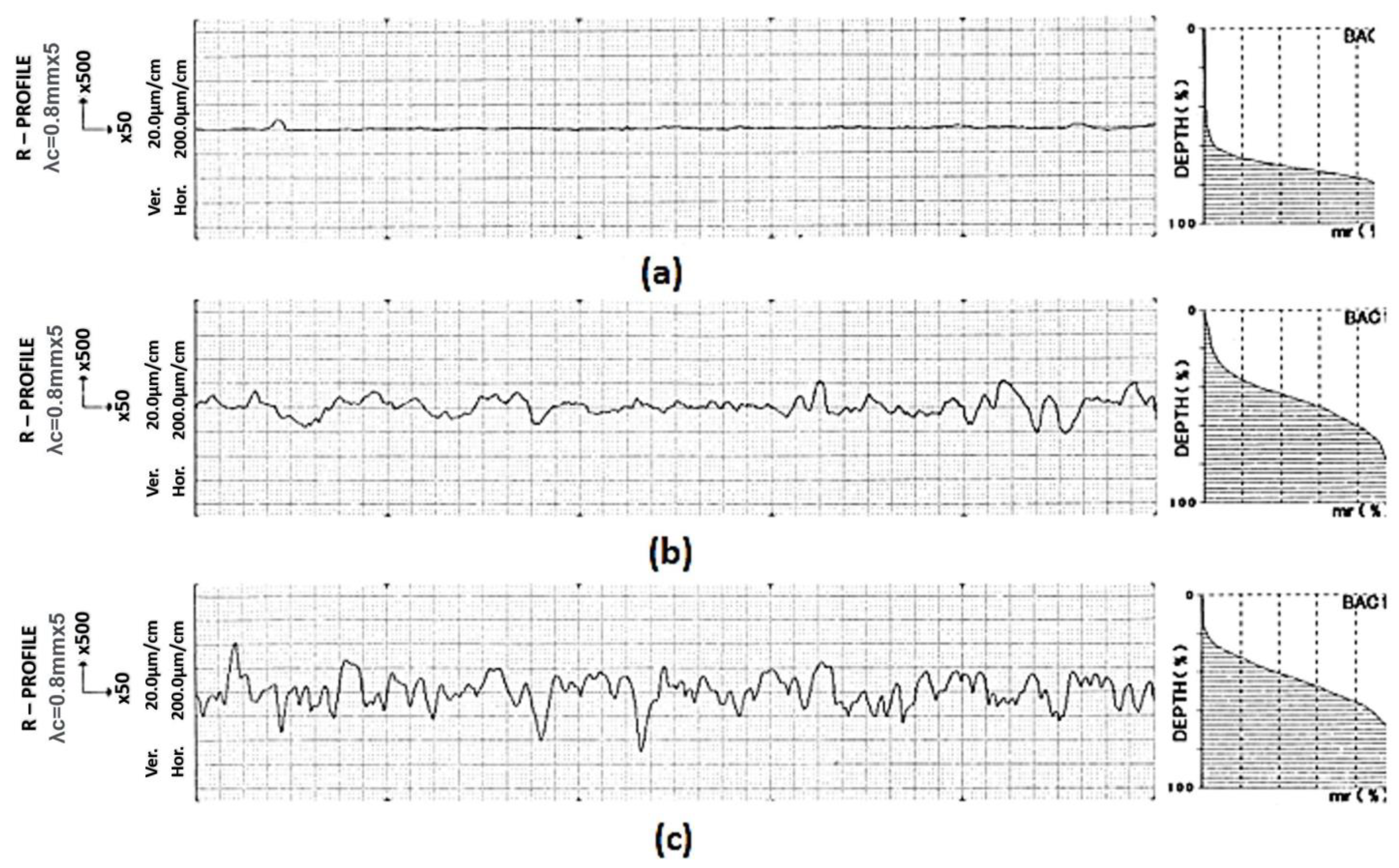
The adhesion of the adhesive to the bonded material is fundamental to the cohesion mechanism of the joint. To increase it, surface pretreatment by grinding of the contact surfaces was used. From the above records, the greatest surface roughness was obtained in the direction perpendicular to the grinding direction, i.e., in the direction in which the loading force was applied in each type of test. The Ra value of 0.34 µm increased to 5.04 µm in this direction, the Rz value of 2.49 µm increased to 29.74 µm, and the Rt increased from 5.67 µm to 45.48 µm. The recordings of the contact surface profiles of the bonded joints are shown in Figure 4, and the change in the nature of the surface microgeometry before and after grinding of the bonded joints is shown in Figure 5.
3.2. Assessment of the Tensile Strength Test of Bonded Joints after Curing
The measured tensile strength test values for the different types of adhesives, when three different thicknesses were used, are described in Table 5, and a graphical comparison of the tensile strength test is shown in Figure 6.
The graphical representation of the shear strength showed that the ChS EPOXY 1200 adhesive achieved the highest shear strength values, the DINITROL 860 adhesive had a lower value, and the MEGABOND 2000 adhesive achieved the lowest strength value. When the effect of adhesive thickness on the shear strength of the joint is evaluated, it is found that the highest strength values are achieved by adhesives with thicknesses of 0.33 mm, except for DINITROL 860, where the highest strength was achieved with an adhesive thickness of 0.25 mm. The characteristic fracture surface appearances for different types and thicknesses of adhesives are shown in Table 6. The failure modes of the tested bonded joints were analysed according to the standard [70].
Dinitrol adhesive is based on a different material base than the other adhesives (Megabond, ChS Epoxy (Marstol-Domsel DmbH, Zülpich, Germany), which affects the strength of the bonded joints at all three thicknesses. Dinitrol is a flexible PU adhesive, its advantages are mainly in the dynamic stressing of joints. Corrosion tests did not significantly reduce the strength of the joint.
For all specimens bonded with the same type of adhesive of a given thickness, adhesive failure of the bonded joint was observed. In the case of Dinitrol adhesive, 100% adhesive failure was observed. Table 6 shows the types of failure of bonded joints. It is possible to observe areas with typical adhesive failure (Dinitrol 860) and areas with cohesive failure (adhesive MEGABOND 2000, thickness 0.1 and 0.2 mm, adhesive ChS EPOXY 1200, thickness 0.2 and 0.3 mm). For bonded joints with adhesive failure, there was low adhesion between the adhesive and the material, it is possible to recommend for further experimental work a higher quality of pre-treatment of the surface of the contact areas.
3.2.1. Strength Properties Evaluation of Bonded Joints in Environment with SO2 Condensation
The measured changes in shear strength values for the individual adhesive types after exposure of the joints in the above environment are shown in Table 7 and their graphical processing is shown in Figure 7.
From the graphical representation of the change in strength properties after curing and after exposure to the above environment, the MEGABOND 2000 adhesive showed a significant decrease in strength at all three thicknesses due to the change in environment. The most marked difference was obtained at 0.33 mm thickness, more than four times the values measured after base curing. Table 8 shows the characteristic fracture surface appearances for MEGABOND 2000 adhesive for three different thicknesses. The appearance of the fracture surfaces was similar for all specimens bonded with the same type of adhesive of a given thickness. The following failures of the bonded joint.
The same analysis was carried out for the second type of adhesive-ChS EPOXY 1200, where the measured bond failure forces can be seen in Table 9 and a graphical comparison is shown in Figure 8.
A comparison of the graphical representation of the change in shear strength after curing and after exposure in the condensing chamber shows that for the ChS EPOXY 1200 adhesive, there was a reduction in strength for all three adhesive thicknesses due to the change in environment. However, there was not as significant a decrease in strength as for the MEGABOND 2000 type adhesive.
Table 10 shows the characteristic fracture surface appearances for ChS EPOXY 1200 adhesive of three different thicknesses. For all specimens bonded with this adhesive of a given thickness, adhesive failure of the bonded joint occurred. The adhesive layer stayed unbroken, and the interface remained clean, with sanding marks visible on the opposing surface.
The last analysis was a comparison of DINITROL 860 adhesive, where the measured loads at bond failure are shown in Table 11 and a graphical comparison is shown in Figure 9.
The graphical representation of the change in shear strength after curing and after exposure to the above environment shows that for DINITROL 860 adhesive the change in environment resulted in a decrease in strength for all three adhesive thicknesses. At 0.25 mm adhesive thickness, the strength of the bonded joint decreased significantly due to the change in environment. Table 12 shows the characteristic fracture surface appearances for DINITROL 860 adhesive of three different thicknesses. The appearance of the fracture surfaces was similar for all specimens bonded with this type of adhesive of a given thickness. This was an adhesive failure of the bonded joint.
3.2.2. Strength Properties Evaluation of Bonded Joints in Atmospheric Conditions for One Year
A thickness of 0.1 mm was chosen to compare the effect of bonding factors on the shear of the bonded joints after curing and after exposure to realistic atmospheric conditions for one year. The measured average bond failure loads measured after curing and exposure of the joints are shown in Figure 10.
The graphical representation of the change in shear strength after curing and after exposure to realistic atmospheric conditions for one year shows that there was a decrease in strength for all three types of adhesives. The decrease in strength was not significant as this was a short period of time for evaluating the change in strength of the bonded joint.
Table 13 shows the characteristic fracture surface appearances for each type of adhesive with an adhesive thickness of 0.1 mm. For all specimens bonded with this adhesive of a given thickness, adhesive failure of the bonded joint was observed.
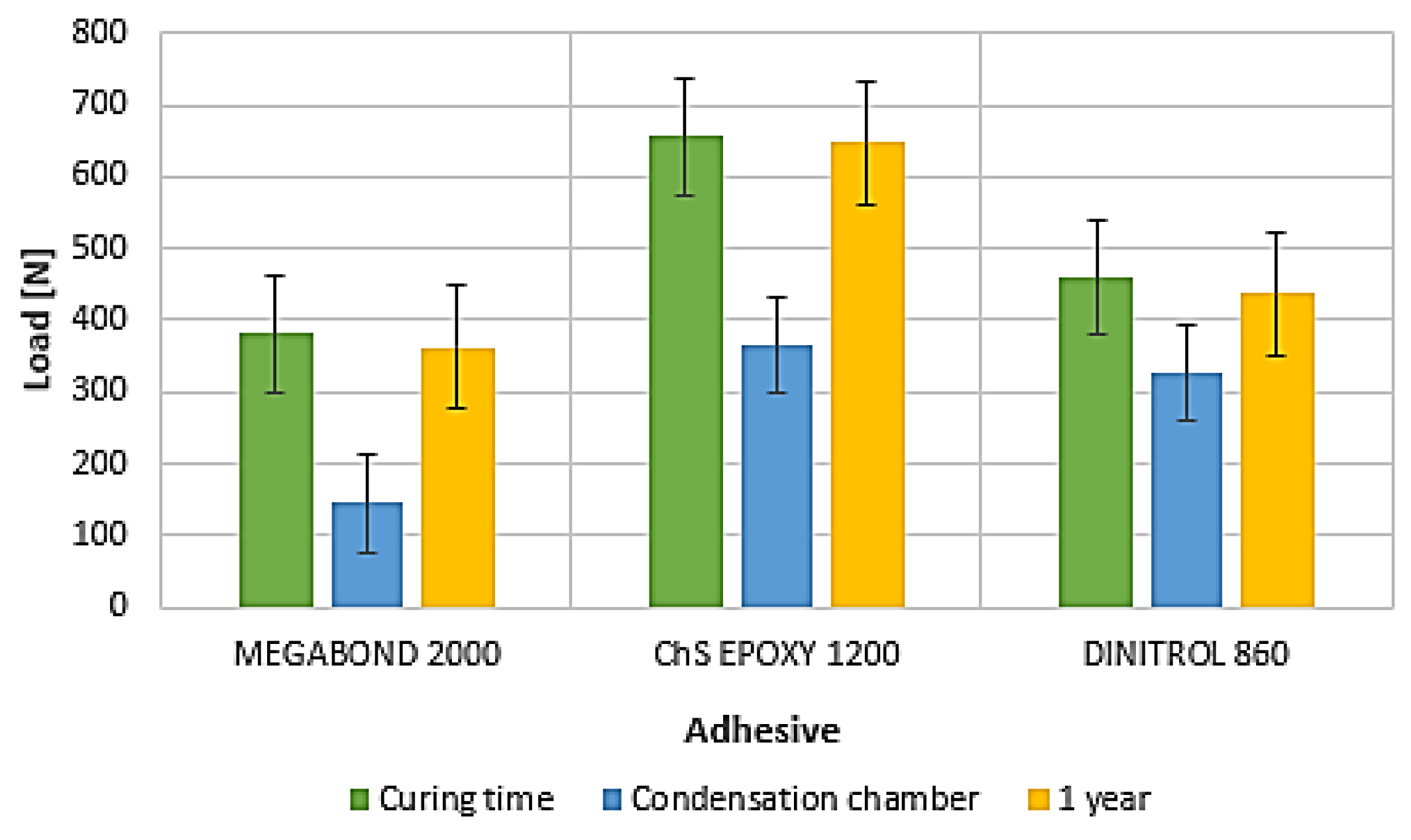
For the complete evaluation of the changes in strength properties after curing and after exposure in different environments for all three types of adhesives, an adhesive thickness of 0.1 mm was chosen. The measured bond failure loads for each adhesive type are shown in Table 14 and their graphical representation is shown in Figure 11.
Individual shear strength comparisons for the three different adhesives with respect to the environment showed that the ChS EPOXY 1200 adhesive achieved the best strength results. It can be concluded that the use of the curing agent that was used in the application phase created higher adhesion forces between the adherend and the adhesive, resulting in an increase in the strength of these joints for all three adhesive thicknesses.
3.3. Assessment of the Impact Strength of Bonded Joints
The bonded joints for the impact strength evaluation were made following the methodology described in Section 2.6. The bonded joints were evaluated after curing and exposure in different environments, namely in an environment with the presence of SO2 at total moisture condensation, during immersion in a 20% salt solution and under realistic atmospheric conditions for one year. A thickness of 0.1 mm was chosen to compare the effect factors of bonded joints after curing and exposure in different environments.
The measured values of impact strength of bonded joints for different types of adhesives of different thicknesses are shown in Table 15 and graphically processed in Figure 12.
The highest value of impact strength after curing was achieved by ChS EPOXY 1200 adhesive, a lower value was achieved by MEGABOND 2000, and the lowest value of impact strength was achieved by DINITROL 860 adhesive.
In terms of adhesive thickness applied, it was observed that the highest strength values were achieved by adhesives with thicknesses of 0.33 mm, except for the DINITROL 860 type adhesive, where the highest strength was achieved at 0.1 mm adhesive thickness. Table 16 shows the characteristic fracture surface appearances for each adhesive type and thickness. For all specimens bonded with the same type of adhesive of a given thickness, adhesive failure of the bonded joint occurred. In several cases, it was possible to evaluate the fracture failures as an adhesive.
3.3.1. Impact Strength Evaluation of Bonded Joints in Environment with SO2 Condensation
The measured changes in the impact strength values of the bonded joints for each adhesive type are given in Table 17, and the graphical representation is shown in Figure 13.
A graphical comparison of the change in impact strength after curing and after exposure in the condensing chamber shows that all three types of adhesives showed a significant decrease in strength due to the change in environment, especially for the MEGABOND 2000 adhesive type.
Table 18 shows the characteristic fracture surface appearances for each adhesive type with 0.1 mm adhesive thickness. For MEGABOND 2000, an 80% adhesive and 20% cohesive failure can be identified. For the other adhesive types, adhesive failure occurred.
3.3.2. Impact Strength Evaluation of Bonded Joints after Exposure to a 20% Salt Solution
After exposure of the specimens to the saline solution, the bonded joints were impact stressed. The measured values of the impact strength of the bonded joints for the different types of adhesives are shown in Table 19 and graphically processed in Figure 14.
A graphical comparison of the change in the impact strength of the joints after curing and after exposure to the saline solution shows that there was a decrease in strength for all three types of adhesives due to the change in environment.
Table 20 shows the characteristic fracture surface appearances for each type of adhesive with 0.1 mm adhesive thickness. For all specimens bonded with the same type of adhesive of a given thickness, adhesive failure of the bonded joint occurred.
3.3.3. Impact Strength Evaluation of Bonded Joints after Exposure in Atmospheric Conditions for One Year
The specimens were impact-stressed after exposure to the above environment. The measured values of the impact strength of the bonded joints for each adhesive type are shown in Table 21 and graphically processed in Figure 15.
A graphical comparison of the change in the impact strength of the joints after curing and after exposure under realistic atmospheric conditions for one year shows that only the MEGABOND 2000 type adhesive showed a decrease in impact strength, as it was a two-component adhesive (epoxy-acrylate). As it was a combination of atmospheric factors, some of them could have influenced the impact strength, such as diffusion of water into the adhesive layer, etc.
ChS EPOXY 1200 and DINITROL 860 type adhesives are better able to withstand atmospheric conditions, as the impact strength of these two adhesives increased due to environmental influences. We suppose that curing of the adhesives has occurred.
Table 22 shows the characteristic fracture surface appearances for different types of adhesives with 0.1 mm adhesive thickness. The appearance of the fracture surfaces was similar for all specimens bonded with the same type of adhesive of a given thickness. For the ChS EPOXY 1200 adhesive, an 80% adhesive and 20% cohesive failure could be observed. The other adhesive types showed adhesive failure.
An overall assessment of the changes in impact strength after curing and after exposure to different environments for all three types of 0.1 mm thick adhesives is shown in Table 23, and their graphical representation is shown in Figure 16.
The highest impact strength values were achieved by MEGABOND 2000 adhesive and the lowest by DINITROL 860 in curing time. Exposure of the joints to an environment with SO2 in the presence of total moisture condensation, as well as immersion in a 20% solution of industrial sprinkling salt, significantly reduced the impact strength values for all adhesives evaluated. The change in impact strength after curing and exposure to realistic atmospheric conditions for one year shows that ChS EPOXY 1200 and DINITROL 860 adhesives are better able to withstand atmospheric conditions. Their impact strength increased due to the above-mentioned environment. We suppose that curing of the adhesives has occurred.
4. Discussion
Since several adhesives are used in practice, it is useful to know their behaviour in terms of strength. As the application of adhesives is in the field of renovation, it must be considered that these adhesives in the form of joints of plastic parts are exposed to various external influences. Therefore, the aim of this paper was to select the three most widely used adhesives and compare them with each other, with tensile and impact tests being chosen as evaluation tests. The selection of the chosen tests was due to the most common stressing of plastic parts in practice. To complete the knowledge of the strength of the adhesive used, bonded joints of three different thicknesses were created and then subjected to the effects of the sprinkling agents based on simulated industrial operating conditions. In the case of tensile properties, this involved exposure in an environment with the presence of SO2 and exposure for 1 year under realistic atmospheric conditions. In the case of impact strength, the environments chosen were the ones with the presence of SO2, the 20% salt solution environment, and, again, exposure for 1 year under realistic atmospheric conditions.
The adhesive thickness significantly influences the load-bearing capacity of the joints. Experimental work has confirmed the dependence of the adhesive thickness and the strength of the joint. It depends on the specific type of adhesive, the method of loading, and the conditions to which the joint is subjected.
The effect of weather conditions is to degrade and reduce the strength properties of adhesives used in bonded joints. The degree of degradation depends on the specific loading conditions and the type of adhesive used. The reduction of the mechanical properties of the bonded joint can negatively affect its strength. Bonding allows flexible fixation of sheet metal while achieving higher stiffness and strength of the car body. Degradation of the adhesive can reduce the tightness of the joints, which affects the anti-corrosion properties of the bodywork and the service life of the vehicle. The adhesive layer, therefore, represents an electrical isolant, which, by breaking the integrity of the joint, can cause electrolytic corrosion. Similarly, a breach in the integrity of the bond may also increase the sound level of the vehicle as well as reduce the strength of the bodywork in the case of crashes.
The individual results demonstrated the following claims:
- The highest values of load at failure after curing were achieved by ChS EPOXY 1200, a lower value was achieved by DINITROL 860, and the lowest value was achieved by MEGABOND 2000.
- When comparing the adhesives used and the individual adhesive thicknesses of 0.1 mm, 0.25 mm, and 0.33 mm, with respect to the post-cure condition and after exposure to an environment with SO2 present, there was a decrease of load at failure with the change in environment for each adhesive. The least affected results were obtained from the ChS EPOXY type adhesive compared to the MEGABOND 2000 and DINITROL 860 adhesives. For the MEGABOND 2000 adhesive, the most significant difference was achieved at 0.33 mm thickness, more than four times the values measured after curing. The same trend in the form of a decrease in strength was obtained for all three adhesives that were exposed to realistic atmospheric conditions for one year compared to the samples after curing.
- Individual shear strength comparisons of the three different adhesives, with respect to the environment, showed that the best strength results were achieved by the ChS EPOXY 1200 adhesive. It can be concluded that the use of the curing agent that was used in the application phase created greater adhesive forces between the adherend and the adhesive, resulting in an increase in the strength of these joints for all three adhesive thicknesses. In the case of bond failure, it was more likely an adhesive failure.
- In the case of the impact strength evaluation after curing, the highest impact values were obtained from the adhesive type ChS EPOXY 1200. In terms of the thickness of adhesive used, it was found that the highest strength values were achieved by adhesives with a thickness of 0.33 mm, except for DINITROL 860 type adhesive, where the highest strength was achieved with an adhesive thickness of 0.1 mm. Dinitrol adhesive is based on a different material base than other evaluated adhesive-flexible polyurethanes. For this reason, it showed the highest strength at a thickness of 0.1 mm.
- When comparing the impact strength of the individual adhesives in the post-cure and post-exposure conditions in the different environments, where only one adhesive thickness of 0.1 mm was used, an 8 times decrease in bond strength was observed from the MEGABOND 2000 adhesive type when SO2 was used, a 10 times decrease in bond strength when 20% salt solution was used, and a 2 times decrease when exposed for 1 year compared to the other adhesives used.
- For the ChS EPOXY and DINITROL 860 adhesives, an increase in bond strength was obtained when the joints were exposed for 1 year compared to the samples after curing. There was a 12% increase for ChS EPOXY adhesive and a 13% increase for DINITROL 860 adhesive. It can be concluded that further curing of the adhesive occurred.
- For ChS EPOXY and DINITROL 860 adhesives, an increase in impact strength was achieved when the joints were exposed for 1 year compared to the samples after curing. This was a 12% increase for the ChS EPOXY adhesive and a 13% increase for the DINITROL 860 adhesive. It can be concluded that further curing of the adhesive occurred.
5. Conclusions
From the point of view of our research, it can be concluded that for the purpose of application of bonding technology, the MEGABOND type adhesive is not suitable for the use and renovation of plastic parts when these parts are exposed to several external influences. The best values among the MEGABOND 2000, ChS EPOXY, and DINITROL 860 adhesives are achieved by the ChS EPOXY adhesive, which can be recommended for the renovation of plastic parts for the automotive industry. ChS EPOXY 1200 is epoxy-based and resists water, weather conditions, and sunlight well.
The following directions and challenges are offered for further study in this field:
- Due to the high increment of adhesives and materials used in the automotive industry, it is necessary to predict their behaviour under different loads because of which various simulation tools can be applied. Their use can provide us with more detailed information about the behaviour of the adhesive joint when evaluating mechanical tests, but also under different loads. There is also the question of how the adhesive will perform under the influence of different loads at the point of contact, supported by computer simulation, in which it is possible to compare the results obtained from the simulation with the real results and, thereby, verify the degree of reliability of the results obtained from the simulation. Therefore, one of the other possibilities of the study is the application of simulation tools for the bonding technology process.
- Another area of interest could be the re-investigation of the adhesive thickness in the bonding process, as well as in the use of heterogeneous materials such as composites, which are finding more and more applications in the automotive industry. Due to the possibility of delamination occurring, e.g., during drilling and subsequently bonding, various composite materials based on carbon, aramid, or glass fibres could be used for experimental applications, to focus on a non-destructive bonding method, such as the bonding technology in question.
- Another study could analyse the bonding of hybrid materials, i.e., materials with different bases, such as metal-plastic, steel-aluminium, and other combinations. The reason for this is the fast increase in the production of cars in combination with these materials, as well as the use of composite materials, which requires knowledge not only of the properties of the individual adhesives, but also of their capabilities and the strengths of the individual joints that can be expected in the construction of cars.
- The last task in this area could be the application of an adhesive to a bolt or rivet joint and the monitoring of the effect of the adhesive on the strength of that joint, or the application of an adhesive in flow drill technology, which involves friction drilling.
Author Contributions
Conceptualization, J.V.; methodology, J.V. and J.B. (Jakub Brezina); validation, J.B. (Janette Brezinová); formal analysis, J.V. and J.B. (Janette Brezinová); investigation, J.V.; resources, J.V.; writing—original draft preparation, J.V.; writing—review and editing, J.V.; visualization, J.V. and J.B. (Janette Brezinová); supervision, J.B. (Janette Brezinová); project administration, J.V. and J.B. (Janette Brezinová); funding acquisition, J.B. (Janette Brezinová). All authors have read and agreed to the published version of the manuscript.
Funding
This research was funded by The Ministry of Education, Science, Research, and Sport of the Slovak Republic, grant number VEGA 1/0597/23, APVV-20-0303, KEGA 036TUKE-4/2021.
Institutional Review Board Statement
Not applicable.
Informed Consent Statement
Not applicable.
Data Availability Statement
The data presented in this study are available on request from the corresponding author. The data are not publicly available due to privacy.
Conflicts of Interest
The authors declare no conflicts of interest.
Nomenclature
| EPDM | Ethylene Propylene Diene Monomer |
| PP | Polypropylene |
| CFRP | Carbon fiber-reinforced polymers |
| FMS | Flexible manufacturing systems |
| FRP | Fibre-reinforced plastic |
| Ra | Arithmetical mean height |
| Rz | Maximum height of profile |
| Rt | Total Height Of Profile |
| IC | Integrated Circuit |
| UV | Ultraviolet |
| h | Hour |
References
- Martins, A.V.; Godina, R.; Azevedo, Z.G.; Carvalho, H. Towards the development of a model for circularity: The circular car as a case study. Sustain. Energy Technol. Assess. 2021, 45, 101215. [Google Scholar] [CrossRef]
- Bultó, R.; Viles, E.; Mateo, R. Overview of ramp-up curves: A literature review and new challenges. Proc. Inst. Mech. Eng. Part B J. Eng. Manuf. 2016, 232, 755–765. [Google Scholar] [CrossRef]
- Kaščák, L.; Cmorej, D.; Slota, J.; Spišák, E.; Varga, J. Numerical and experimental studies on clinch-bonded hybrid joining of steel sheet DX53D+Z. Acta Metall. Slovaca 2022, 28, 219–223. [Google Scholar] [CrossRef]
- Kim, J.K.; Lee, D.G. Characteristics of plasma surface treated composite adhesive joints at high environmental temperature. Composite Structures 2002, 57, 37–46. [Google Scholar] [CrossRef]
- Silva, L.F.M.; Adams, R.D. Joint strength predictions for adhesive joints to be used over a wide temperature range. Int. J. Adhes. Adhes. 2007, 27, 362–379. [Google Scholar] [CrossRef]
- Shan, Z.D.; Liu, F.; Zhan, L.; Lin, Z.L. Rapid patternless casting technology on CNC manufacturing. Advanced Materials Research. Adv. Mater. Res. 2010, 97–101, 4036–4041. [Google Scholar] [CrossRef]
- Sarrado, C.; Turon, A.; Costa, J.; Renart, J. On the validity of linear elastic fracture mechanics methods to measure the fracture toughness of adhesive joints. Int. J. Solids Struct. 2016, 81, 110–116. [Google Scholar] [CrossRef]
- Budhe, S.; Bane, M.D.; de Barrosa, S.; da Silva, L.F.M. An updated review of adhesively bonded joints in composite materials. Int. J. Adhes. Adhes. 2017, 72, 30–42. [Google Scholar] [CrossRef]
- Martínez-Landeros, V.H.; Vargas-Islas, S.Y.; Cruz-González, C.E.; Barrerad, S.; Mourtazov, K.; Ramírez-Bon, R. Studies on the influence of surface treatment type, in the effectiveness of structural adhesive bonding, for carbon fiber reinforced composites. J. Manuf. Processes 2019, 39, 160–166. [Google Scholar] [CrossRef]
- Greškovič, F.; Varga, J.; Dulebová, Ľ.G.C. The utilize of gamma radiation on the examination of mechanical properties of polymeric materials. Metalurgija 2012, 51, 245–248. [Google Scholar] [CrossRef]
- Campilho, R.D.S.G. Design of Adhesive Bonded Joints. Processes 2023, 11, 3369. [Google Scholar] [CrossRef]
- Bidadi, J.; Saeidi Googarchin, H.; Akhavan-Safar, A.; Carbas, R.J.C.; da Silva, L.F.M. Characterization of Bending Strength in Similar and Dissimilar Carbon-Fiber-Reinforced Polymer/Aluminum Single-Lap Adhesive Joints. Appl. Sci. 2023, 13, 12879. [Google Scholar] [CrossRef]
- Sadık, A.; Karabudak, F. Strength Analysis in Bonded, Bolted and Bolted-Bonded Joints, Single Lap Joints, Metal/Composite Plates. Appl. Sci. 2023, 13, 10476. [Google Scholar] [CrossRef]
- Džupon, M.; Kaščák, Ľ.; Cmorej, D.; Čiripová, L.; Mucha, J.; Spišák, E. Clinching of High-Strength Steel Sheets with Local Preheating. Appl. Sci. 2023, 13, 7790. [Google Scholar] [CrossRef]
- Razavi, N.; Berto, F.; Peron, J.; Torgersen, J. Parametric study of adhesive joints with non-flat sinusoid interfaces. Theor. Appl. Fract. Mech. 2018, 93, 44–55. [Google Scholar] [CrossRef]
- Reis, P.N.B.; Soares, J.R.L.; Pereira, A.M.; Ferreira, J.A.M. Effect of adherends and environment on static and transverse impact response of adhesive lap joints. Theor. Appl. Fract. Mech. 2015, 80, 79–86. [Google Scholar] [CrossRef]
- Ciardiello, R.; Niutta, C.B.; Goglio, L. Adhesive Thickness and Ageing Effects on the Mechanical Behaviour of Similar and Dissimilar Single Lap Joints Used in the Automotive Industry. Processes 2023, 11, 433. [Google Scholar] [CrossRef]
- Ciardiello, R.; D’Angelo, D.; Cagna, L.; Croce, A.; Paolino, D.S. Effects of plasma treatments of polypropylene adhesive joints used in the automotive industry. J. Mech. Eng. Sci. 2021, 236, 6204–6218. [Google Scholar] [CrossRef]
- Turowski, A.; Adamiec, J. Mechanical Properties of WE43 Magnesium Alloy Joint at Elevated Temperatur. Arch. Metall. Mater. 2015, 60, 1–9. [Google Scholar] [CrossRef]
- Banea, M.D.; Rosioara, M.; Carbas, R.J.C.; Silva, L.F.M. Multi-material adhesive joints for automotive industry. Compos. Part B 2018, 151, 71–77. [Google Scholar] [CrossRef]
- Cavezza, F.; Boehm, M.; Terryn, H.; Haufman, T. A Review on Adhesively Bonded Aluminium Joints in the Automotive Industry. Metals 2020, 10, 730. [Google Scholar] [CrossRef]
- So, H.W.; Chen, N.N.; Niem, P.I. Fatigue performance of adhesive joints immersed in different solutions. J. Adhes. 1994, 44, 245–256. [Google Scholar] [CrossRef]
- Sabadka, D.; Kender, Š. Unconventional Methods of Joining Composites and Metals in the Context of Weight Reduction of Car Bodies. Adv. Sci. Technol. Res. J. 2023, 17, 230–242. [Google Scholar] [CrossRef]
- Golio, L.; Rosetto, M. Impact rupture of structural adhesive joints under different stress combinations. Int. J. Impact Eng. 2008, 35, 635–643. [Google Scholar] [CrossRef]
- Verma, R.; Sharma, L.; Arora, K.S.; Chauhan, M.; Chhibber, R. Experimental investigation on adhesive bonding of similar and dissimilar weld joint used for automotive applications. Proc. Inst. Mech.Eng. Part E J. Process Mech. Eng. 2021, 236, 752–761. [Google Scholar] [CrossRef]
- Jeevi, G.; Nayak, S.K.; Kader, M.A. Review on adhesive joints and their application in hybrid composite structures. J. Adhes. Sci. Technol. 2019, 33, 1497–1520. [Google Scholar] [CrossRef]
- Queiroz, H.F.M.; Banea, M.D.; Cavalcanti, D.K.K. Adhesively bonded joints of jute, glass and hybrid jute/glass fibre-reinforced polymer composites for automotive industry. Appl. Adhes. Sci. 2021, 9, 2. [Google Scholar] [CrossRef]
- Pisharody, A.P.; Blandford, B.; Kováč, D.E.; Jack, D.A. An experimental investigation on the effect of adhesive distribution on strength of bonded joints. Appl. Adhes. Sci. 2019, 7, 6. [Google Scholar] [CrossRef]
- Campilho, R.D.S.G.; Moura, D.C.; Banea, M.D.; da Silva, L.F.M. Adherend thickness effect on the tensile fracture toughness of a structural adhesive using an optical data acquisition method. Int. J. Adhes. Adhes. 2014, 53, 15–22. [Google Scholar] [CrossRef]
- Droubi, M.G.; Mcafee, J.; Horne, R.C.; Walker, S.; Klaassen, C.; Crawford, A.; Prathuru, A.K.; Faisal, N.H. Mixed-mode fracture characteristics of metal-to-metal adhesively bonded joints: Experimental and simulation methods. Procedia Struct. Integr. 2017, 5, 40–47. [Google Scholar] [CrossRef]
- Clerc, G.; Brunner, A.J.; Josset, S.; Niemz, P.; Pichelin, F.; van de Kuilen, J.W.G. Adhesive wood joints under quasi-static and cyclic fatigue fracture Mode II loads. Int. J. Fatigue 2019, 123, 40–52. [Google Scholar] [CrossRef]
- Ayatollahi, M.R.; Ajdani, A.; Akhavan-Safar, A.; da Silva, L.F.M. Effect of notch length and pre-crack size on mode II fracture energy of brittle adhesives. Eng. Fract. Mech. 2019, 212, 123–135. [Google Scholar] [CrossRef]
- Lee, C.-S.; Chun, M.-S.; Kim, M.-H.; Lee, J.-M. Delamination failure of multilaminated adhesively bonded joints at low temperatures. Cryogenics 2011, 51, 429–437. [Google Scholar] [CrossRef]
- Blackman, B.R.K.; Kinloch, A.J.; Rodriguez-Sanchez, F.S.; Teo, W.S. The fracture behaviour of adhesively-bonded composite joints: Effects of rate of test and mode of loading. Int. J. Solids Struct. 2012, 49, 1434–1452. [Google Scholar] [CrossRef]
- Ladani, R.B.; Wu, S.; Kinloch, A.J.; Ghorbani, K.; Mouritz, A.P.; Wang, C.H. Enhancing fatigue resistance and damage characterisation in adhesively-bonded composite joints by carbon nanofibers. Compos. Sci. Technol. 2017, 149, 116–126. [Google Scholar] [CrossRef]
- Takeda, T.; Narita, F. Fracture behaviour and crack sensing capability of bonded carbon fibre composite joints with carbon nanotube-based polymer adhesive layer under Mode I loading. Compos. Sci. Technol. 2017, 146, 26–33. [Google Scholar] [CrossRef]
- Quan, D.; Carolan, D.; Rouge, C.; Murphy, N.; Ivankovica, A. Mechanical and fracture properties of epoxy adhesives modified with graphene nanoplatelets and rubber particles. Int. J. Adhes. 2018, 81, 21–29. [Google Scholar] [CrossRef]
- Fan, X.J.; Zhou, J.; Zhang, G.Q.; Chandra, A. Continuum Theory in Moisture-Induced Failures of Encapsulated IC Devices. In Moisture Sensitivity of Plastic Packages of IC Devices; Springer: New York, NY, USA, 2010; pp. 279–299. [Google Scholar] [CrossRef]
- Fan, X.J.; Zhang, G.Q.; Van Driel, W.D.; Ernst, L.J. Interfacial delamination mechanisms during reflow with moisture preconditioning. IEEE Trans. Compon. Packag. Technol. 2008, 31, 252–259. [Google Scholar]
- Dorn, L.; Liu, W. The stress state and failure properties of adhesive-bonded plastic/metal joints. Int. J. Adhes. 1993, 13, 21–31. [Google Scholar] [CrossRef]
- Kah, P.; Suoranta, R.; Martikainen, J.; Magnus, C. Technıques for Joınıng Dıssımılar Materıals: Metals and Polymers. Rev. Adv. Mater. Sci. 2014, 36, 152–164. [Google Scholar]
- Anaç, N. Assessment of Adhesively Bonded Joints of Similar and Dissimilar Materials: Industrial Case Study. Processes 2023, 11, 1312. [Google Scholar] [CrossRef]
- Godzimirski, J.; Komorek, A. The Influence of Selected Test Conditions on the Impact Strength of Adhesively Bonded Connections. Materials 2020, 13, 1320. [Google Scholar] [CrossRef] [PubMed]
- Almansour, F.A.; Dhakal, H.N.; Zhang, Z.Y. Effect of water absorption on Mode I interlaminar fracture toughness of flax/basalt reinforced vinyl ester hybrid composites. Compos. Struct. 2017, 168, 813–825. [Google Scholar] [CrossRef]
- Fernandes, R.L.; de Moura, M.F.S.F.; Moreira, R.D.F. Effect of temperature on pure modes I and II fracture behaviour of composite bonded joints. Compos. Part B Eng. 2016, 96, 35–44. [Google Scholar] [CrossRef]
- Brito, C.B.G.; Sales, R.C.M.; Donadon, M.V. Effects of temperature and moisture on the fracture behaviour of composite adhesive joints. Int. J. Adhes. Adhes. 2020, 100, 102607. [Google Scholar] [CrossRef]
- Adams, R.D.; Harris, J.A. A critical assessment of the block impact test for measuring the impact strength of adhesive bonds. Int. J. Adhes. Adhes. 1996, 16, 61–71. [Google Scholar] [CrossRef]
- Komorek, A.; Godzimirski, J.; Pietras, A. Experimental and Preliminary Numerical Dynamic Analysis of Effect of Sample Geometry on Impact Strength of Adhesive Joints. In Proceedings of the 7th International Conference on Mechanics and Materials in Design, Albufeira, Portugal, 11–15 June 2017; pp. 1013–1014. [Google Scholar]
- ISO 9653:1998; Adhesives—Test Method for Shear Impact Strength of Adhesive Bonds. International Organization for Standardization ISO: Geneva, Switzerland, 1998.
- Gursel, A.; Cekirge, H.M. Adhesive Joints Subjected to Impact Loading: A Review. Int. J. Mater. Eng. 2019, 9, 16–21. [Google Scholar] [CrossRef]
- Guzanová, A.; Brezinová, J.; Varga, J.; Džupon, M.; Vojtko, M.; Janoško, E.; Viňáš, J.; Draganovská, D.; Hašuľ, J. Experimental Study of Steel–Aluminum Joints Made by RSW with Insert Element and Adhesive Bonding. Materials 2023, 16, 864. [Google Scholar] [CrossRef]
- Banea, M.D.; Souza, F.S.M.; Silva, L.F.M.; Campilho, R.D.S.G.; Pereira, A.M.B. Effects of Temperature and Loading Rate on the Mechanical Properties of a High Temperature Epoxy Adhesive. J. Adhes. Sci. Technol. 2011, 25, 2461–2474. [Google Scholar] [CrossRef]
- Zhang, F.; Yang, X.; Wang, H.P.; Zhang, X.; Xia, Y.; Zhou, Q. Durability of adhesively-bonded single lap–shear joints in accelerated hygrothermal exposure for automotive applications. Int. J. Adhes. Adhes. 2013, 44, 130–137. [Google Scholar] [CrossRef]
- Ferreira, J.A.M.; Reis, P.N.; Costa, J.D.M.; Richardson, M.O.W. Fatigue behaviour of composite adhesive lap joints. Compos. Sci. Technol. 2002, 62, 1373–1379. [Google Scholar] [CrossRef]
- Reis, P.N.; Ferreira, J.A.M.; Richardson, M.O.W. Effect of the Surface Preparation on PP Reinforced Glass Fiber Adhesive Lap Joints Strength. J. Thermoplast. Compos. Mater. 2011, 25, 3–13. [Google Scholar] [CrossRef]
- Rośkowicz, M.; Godzimirski, J.; Komorek, A.; Jasztal, M. The Effect of Adhesive Layer Thickness on Joint Static Strength. Materials 2021, 14, 1499. [Google Scholar] [CrossRef] [PubMed]
- Matos, L.M.C.; Boucher, X.; Afsarmanesh, H. Smart and Sustainable Collaborative Networks 4.0. In Proceedings of the Working Conference on Virtual Enterprises, PRO-VE 2021, Saint-Étienne, France, 22–24 November 2021. [Google Scholar]
- Varga, J.; Tóth, T.; Frankovský, P.; Dulebová, Ľ.; Spišák, E.; Zajačko, I.; Živčák, J. The influence of automated machining strategy on geometric deviations of machined surfaces. Appl. Sci. 2021, 11, 2353. [Google Scholar] [CrossRef]
- Varga, J.; Stahovec, J.; Beňo, J.; Vrabeľ, M. Assessment of surface quality for chosen milling strategies when producing relief surfaces. Adv. Sci. Technol. Res. J. 2014, 8, 37–41. [Google Scholar] [CrossRef]
- Varga, J.; Spišák, E.; Gajdoš, I.; Mulidrán, P. Comparison of milling strategies in the production of shaped surfaces. Adv. Sci. Technol. Res. J. 2022, 16, 267–274. [Google Scholar] [CrossRef]
- Pereira, A.M.; Reis, P.N.B.; Fereira, J.A.M.; Antunes, F.V. Effect of saline environment on mechanical properties of adhesive joints. Int. J. Adhes. Adhes. 2013, 47, 99–104. [Google Scholar] [CrossRef]
- Srinisivan, D.V.; Ravichandran, V.; Sridhar, I. Failure analysis of GFRP single lap joints tailored with a combination of tough epoxy and hyperelastic adhesives. Compos. Part B Eng. 2020, 200, 108255. [Google Scholar] [CrossRef]
- Durodola, J.F. Functionally graded adhesive joints—A review and prospects Int. J. Adhes. Adhes. 2017, 76, 83–89. [Google Scholar] [CrossRef]
- Wei, K.; Chen, Y.; Li, M.; Yang, X. Strength and Failure Mechanism of Composite-Steel Adhesive Bond Single Lap Joints. Adv. Mater. Sci. Eng. 2018, 2018, 5810180. [Google Scholar] [CrossRef]
- Tomozawa, K. Recent technological innovation in the Japanese automotive industry and its spatial implications for the Kyushu-Yamaguchi area in southwestern Japan. Int. J. Eng. 1992, 2, 234–241. [Google Scholar] [CrossRef]
- PN-EN ISO 6988:2000; Metallic and Other Non-Organic Coatings—Sulfur Dioxide Test With General Condensation Of Moisture. Polish Committee for Standardization: Warszawa, Poland, 2000.
- STN 038135; Evaluation of Strength Properties of Bonded Joints at Full Immersion in Liquids. Slovak Committee for Standardization: Bratislava, Slovak Republic, 1993.
- EN 1465; Adhesives—Determination of Tensile Lap-Shear Strength of Bonded Assemblies. Sorting No. 66 8510; Czech Office for Standards, Metrology and Testing: Prague, Czech Republic, 2009.
- STN 668512; Impact strength of bonded joints. Office for Standardization and Measurements: Prague, Czechoslovakia, 1961.
- ASTM D5573-99(2019); Standard Practice for Classifying Failure Mode in Fibre-Reinforced-Plastic (FRP), volume 99. ASTM International: West Conshohocken, PA, USA, 2005; pp. 1–18, Reapproved 2005. [CrossRef]
Figure 1.
Schematic representation of joint formation by bonding process for the Charpy impact test. (a) Distance wire insert and application of the adhesive layer, (b) application of the substrate 2, and (c) force loading of the specimens.
Figure 1.
Schematic representation of joint formation by bonding process for the Charpy impact test. (a) Distance wire insert and application of the adhesive layer, (b) application of the substrate 2, and (c) force loading of the specimens.

Figure 2.
The shape and dimensions of the samples for the tensile strength test.

Figure 3.
The shape and dimensions of the samples for the impact strength test.

Figure 4.
Recordings of the surface profiles of the bonded joint contact surfaces before grinding (a), after grinding in the grinding direction (b), and perpendicular to the grinding direction (c).
Figure 4.
Recordings of the surface profiles of the bonded joint contact surfaces before grinding (a), after grinding in the grinding direction (b), and perpendicular to the grinding direction (c).

Figure 5.
Profilograms of the surface profiles of the bonded joint contact surfaces before grinding (a), after grinding in the grinding direction (b), and perpendicular to the grinding direction (c).
Figure 5.
Profilograms of the surface profiles of the bonded joint contact surfaces before grinding (a), after grinding in the grinding direction (b), and perpendicular to the grinding direction (c).

Figure 6.
Comparison of shear strength after curing for tensile test.

Figure 7.
Comparison of shear strength after curing and SO2 environment for MEGABOND 2000.

Figure 8.
Comparison of shear strength after curing and SO2 environment for ChS EPOXY 1200.

Figure 9.
Comparison of shear strength after curing and SO2 environment for DINITROL 860.

Figure 10.
The shape and dimensions of the samples for tensile strength test.

Figure 11.
Comparison of strength properties for different environments.

Figure 12.
Comparison of impact strength after curing, impact strength.

Figure 13.
Impact strength comparison after curing and SO2 environment.

Figure 14.
Impact strength comparison after exposure to a 20% salt solution.

Figure 15.
Impact strength comparison after exposure in atmospheric conditions for one year.

Figure 16.
Impact strength comparison for different environments for all adhesives used.


Table 1.
The advantages and disadvantages of bonded joints.
| Advantages of Bonded Joints | Disadvantages of Bonded Joints |
|---|---|
| Weight reduction, joint tightness. | Full strength is achieved only after curing. |
| Different materials can be bonded together. | Low resistance to increased temperature. |
| Smooth exterior surfaces. | Requirement of surface treatment before bonding. |
| Possibility of joining large areas. | Curing agents are required. |
| Bond is permanent, making the bond more consistent with stress distribution across the bonded surface. | Long curing times. |
| Possibility to bond very thin materials. | High requirements for flatness and surface finish of the surface of the bonded parts. |
| Most adhesives have good mechanical absorption properties (noise reduction, vibration reduction). | Load possibility of the bonded joint only after a defined period of time. |
| High bond strength, especially at shear and impact strength. |
Table 2.
Adhesives used in automotive repair.
| Adhesive | Components | Curing Method | Application |
|---|---|---|---|
| Polyurethane | 1 | air | bodywork sealant |
| Polyurethane | 1 | hardener | bonding of face glasses |
| Epoxy | 2 | hardener | body parts bonding during repairs |
Table 3.
The view of the mechanical properties of selected material PP-EPDM with talc additive.
| Tensile Modulus [MPa] | Yield Stress [MPa] | Brinell Hardness [MPa] | Strain at Break [%] | Charpy Notched Impact Strength +23 °C [kJ/m2] | Charpy Notched Impact Strength −30 °C [kJ/m2] |
|---|---|---|---|---|---|
| 1100 | 23 | 44 | 40 | 25 | 5 |
Table 4.
The view of the test operating conditions.
| Test Operating Conditions | Tensile Test | Charpy Impact Test |
|---|---|---|
| Environment with SO2 condensation | yes | yes |
| Exposure to a 20% salt solution | no | yes |
| Real atmospheric conditions for one year | yes | yes |
Table 5.
Measured loads at joint failure–tensile test.
| Adhesive | Adhesive Thickness [mm] | Load at Failure [N] |
|---|---|---|
| Megabond 2000 | 0.1 | 382 |
| 0.25 | 318 | |
| 0.33 | 503 | |
| ChS EPOXY 1200 | 0.1 | 656 |
| 0.25 | 635 | |
| 0.33 | 663 | |
| DINITROL 860 | 0.1 | 460 |
| 0.25 | 597 | |
| 0.33 | 543 |
Table 6.
Fracture surface appearance after curing and tensile test.
| Adhesive Thickness | MEGABOND 2000 | ChS EPOXY 1200 | DINITROL 860 |
|---|---|---|---|
| 0.1 |  |  |  |
| 0.2 |  |  |  |
| 0.3 |  |  |  |
Table 7.
Measured loads at joint failure for Megabond 2000 adhesive.
| Adhesive | Adhesive Thickness [mm] | Load at Failure [N] |
|---|---|---|
| Megabond 2000 | 0.1 | 145 |
| 0.25 | 203 | |
| 0.33 | 120 |
Table 8.
Fracture surface appearances of MEGABOND 2000 adhesive for three different thicknesses.
| Adhesive Type | Bond Failure |
|---|---|
| MEGABOND 2000 Adhesive thickness 0.1 mm Bond failure: adhesive |  |
| MEGABOND 2000 Adhesive thickness 0.25 mm Bond failure: adhesive mixed |  |
| MEGABOND 2000 Adhesive thickness 0.33 mm Bond failure: adhesive mixed |  |
Table 9.
Measured loads at joint failure for ChS EPOXY 1200 adhesive.
| Adhesive | Adhesive Thickness [mm] | Load at Failure [N] |
|---|---|---|
| ChS EPOXY 1200 | 0.1 | 365 |
| 0.25 | 348 | |
| 0.33 | 442 |
Table 10.
Fracture surface appearances of ChS EPOXY 1200 adhesive for three different thicknesses.
| Adhesive Type | Bond Failure |
|---|---|
| ChS EPOXY 1200 Adhesive thickness 0.1 mm Bond failure: adhesive |  |
| ChS EPOXY 1200 Adhesive thickness 0.25 mm Bond failure: adhesive |  |
| ChS EPOXY 1200 Adhesive thickness 0.33 mm Bond failure: adhesive |  |
Table 11.
Measured loads at joint failure for DINITROL 860 adhesive.
| Adhesive | Adhesive Thickness [mm] | Load at Failure [N] |
|---|---|---|
| DINITROL 860 | 0.1 | 326 |
| 0.25 | 103 | |
| 0.33 | 263 |
Table 12.
Fracture surface appearances for DINITROL 860 adhesive for three different thicknesses.
| Adhesive Type | Bond Failure |
|---|---|
| DINITROL 860 Adhesive thickness 0.1 mm Bond failure: adhesive |  |
| DINITROL 860 Adhesive thickness 0.25 mm Bond failure: adhesive |  |
| DINITROL 860 Adhesive thickness 0.33 mm Bond failure: adhesive |  |
Table 13.
Fracture surface appearance after atmospheric conditions for one year.
| Adhesive Type | Bond Failure |
|---|---|
| MEGABOND 2000 Adhesive thickness 0.1 mm Bond failure: adhesive |  |
| ChS EPOXY 1200 Adhesive thickness 0.1 mm Bond failure: adhesive mixed |  |
| DINITROL 860 Adhesive thickness 0.1 mm Bond failure: adhesive mixed |  |
Table 14.
Measured loads at joint failure for all adhesives.
| Adhesive | Average Impact Strength [kg.cm−1] Curing Time | Average Strength [N] Condensation Chamber | Average Strength [N] 1 Year |
|---|---|---|---|
| Megabond 2000 | 382 | 145 | 363 |
| ChS EPOXY 1200 | 656 | 365 | 648 |
| DINITROL 860 | 460 | 326 | 437 |
Table 15.
Measured loads at joint failure–impact strength.
| Adhesive | Adhesive Thickness [mm] | Average Impact Strength [kg.cm−1] |
|---|---|---|
| Megabond 2000 | 0.1 | 32.16 |
| 0.25 | 32 | |
| 0.33 | 38.4 | |
| ChS EPOXY 1200 | 0.1 | 23.84 |
| 0.25 | 34.08 | |
| 0.33 | 41.44 | |
| DINITROL 860 | 0.1 | 15.68 |
| 0.25 | 13.76 | |
| 0.33 | 12.8 |
Table 16.
Fracture surface appearance after curing and impact test.
| Adhesive Thickness | MEGABOND 2000 | ChS EPOXY 1200 | DINITROL 860 |
|---|---|---|---|
| 0.1 |  |  |  |
| 0.2 |  |  |  |
| 0.3 |  |  |  |
Table 17.
Measured impact strength values for the specimens after the SO2 environment.
| Adhesive | Average Impact Strength [kg.cm−1] Curing Time | Average Impact Strength [kg.cm−1] Condensation Chamber |
|---|---|---|
| Megabond 2000 | 32.16 | 3.68 |
| ChS EPOXY 1200 | 23.84 | 4.96 |
| DINITROL 860 | 15.68 | 4.48 |
Table 18.
Fracture surface appearance after curing and SO2 environment after impact test.
| Adhesive Type | Bond Failure |
|---|---|
| MEGABOND 2000 Adhesive thickness 0.1 mm Bond failure: adhesive mixed |  |
| ChS EPOXY 1200 Adhesive thickness 0.1 mm Bond failure: adhesive |  |
| DINITROL 860 Adhesive thickness 0.1 mm Bond failure: adhesive |  |
Table 19.
Measured impact strength values for the specimens after exposure to a 20% salt solution.
| Adhesive | Average Impact Strength [kg.cm−1] Curing Time | Average Impact Strength [kg.cm−1] Salt Solution |
|---|---|---|
| Megabond 2000 | 32.16 | 3.2 |
| ChS EPOXY 1200 | 23.84 | 7.2 |
| DINITROL 860 | 15.68 | 6.7 |
Table 20.
Fracture surface appearance after exposure to a 20% salt solution.
| Adhesive Type | Bond Failure |
|---|---|
| MEGABOND 2000 Adhesive thickness 0.1 mm Bond failure: adhesive |  |
| ChS EPOXY 1200 Adhesive thickness 0.1 mm Bond failure: adhesive |  |
| DINITROL 860 Adhesive thickness 0.1 mm Bond failure: adhesive |  |
Table 21.
Measured impact strength values for the specimens after exposure for one year.
| Adhesive | Average Impact Strength [kg.Cm−1] Curing Time | Average Impact Strength [kg.cm−1] 1 Year |
|---|---|---|
| Megabond 2000 | 32.16 | 14.88 |
| ChS EPOXY 1200 | 23.84 | 30.24 |
| DINITROL 860 | 15.68 | 21.6 |
Table 22.
Fracture surface appearance after exposure to atmospheric conditions for one year.
| Adhesive Type | Bond Failure |
|---|---|
| MEGABOND 2000 Adhesive thickness 0.1 mm Bond failure: adhesive mixed |  |
| ChS EPOXY 1200 Adhesive thickness 0.1 mm Bond failure: adhesive mixed |  |
| DINITROL 860 Adhesive thickness 0.1 mm Bond failure: adhesive mixed |  |
Table 23.
Measured impact strength values for each environment used.
| Adhesive | Average Impact Strength [kg.cm−1] After Curing | Average Impact Strength [kg.cm−1] Condensation Chamber | Average Impact Strength [kg.cm−1] Salt Solution | Average Impact Strength [kg.cm−1] 1 Year |
|---|---|---|---|---|
| Megabond 2000 | 32.16 | 3.68 | 3.2 | 14.88 |
| ChS EPOXY 1200 | 23.84 | 4.96 | 7.2 | 30.24 |
| DINITROL 860 | 15.68 | 4.48 | 6.7 | 21.6 |
Disclaimer/Publisher’s Note: The statements, opinions and data contained in all publications are solely those of the individual author(s) and contributor(s) and not of MDPI and/or the editor(s). MDPI and/or the editor(s) disclaim responsibility for any injury to people or property resulting from any ideas, methods, instructions or products referred to in the content. |
© 2023 by the authors. Licensee MDPI, Basel, Switzerland. This article is an open access article distributed under the terms and conditions of the Creative Commons Attribution (CC BY) license (https://creativecommons.org/licenses/by/4.0/).
Share and Cite
MDPI and ACS Style
Varga, J.; Brezinová, J.; Brezina, J. Quality Analysis of Bonded Joints in the Renovation of Plastic Automotive Parts. Appl. Sci. 2024, 14, 271. https://0-doi-org.brum.beds.ac.uk/10.3390/app14010271
AMA Style
Varga J, Brezinová J, Brezina J. Quality Analysis of Bonded Joints in the Renovation of Plastic Automotive Parts. Applied Sciences. 2024; 14(1):271. https://0-doi-org.brum.beds.ac.uk/10.3390/app14010271
Chicago/Turabian StyleVarga, Ján, Janette Brezinová, and Jakub Brezina. 2024. "Quality Analysis of Bonded Joints in the Renovation of Plastic Automotive Parts" Applied Sciences 14, no. 1: 271. https://0-doi-org.brum.beds.ac.uk/10.3390/app14010271
Note that from the first issue of 2016, this journal uses article numbers instead of page numbers. See further details here.