Article

Broadband Continuous-Wave Multi-Harmonic Optical Comb Based on a Frequency Division-by-Three Optical Parametric Oscillator

1
Institute of Photonics Technologies, National Tsing Hua University, Hsinchu 30013, Taiwan
2
Department of Electrical Engineering, National Tsing Hua University, Hsinchu 30013, Taiwan
3
Brain Research Center, National Tsing Hua University, Hsinchu 30013, Taiwan
4
Institute of Atomic and Molecular Sciences, Academia Sinica, No. 1, Roosevelt Rd., Sec. 4, Taipei 10617, Taiwan
5
Department of Physics, National Tsing Hua University, Hsinchu 30013, Taiwan
*
Authors to whom correspondence should be addressed.
Submission received: 12 May 2014 / Revised: 6 November 2014 / Accepted: 10 November 2014 / Published: 26 November 2014

Abstract

:
We report a multi-watt broadband continuous-wave multi-harmonic optical comb based on a frequency division-by-three singly-resonant optical parametric oscillator. This cw optical comb is frequency-stabilized with the help of a beat signal derived from the signal and frequency-doubled idler waves. The measured frequency fluctuation in one standard deviation is ~437 kHz. This is comparable to the linewidth of the pump laser which is a master-oscillator seeded Yb:doped fiber amplifier at ~1064 nm. The measured powers of the fundamental wave and the harmonic waves up to the 6th harmonic wave are 1.64 W, 0.77 W, 3.9 W, 0.78 W, 0.17 W, and 0.11 W, respectively. The total spectral width covered by this multi-harmonic comb is ~470 THz. When properly phased, this multi-harmonic optical comb can be expected to produce by Fourier synthesis a light source consisting of periodic optical field waveforms that have an envelope full-width at half-maximum of 1.59 fs in each period.

1. Introduction

The development of ultrafast physics has made tremendous progress in the past decade. This includes the development of broadband coherent optical sources which are desirable in ultrafast source development as well as in a wide range of research areas including laser spectroscopy and quantum optics [1]. While it is possible to produce ultrashort pulses via Fourier waveform synthesizer at optical frequencies that leads to a periodic train of single-cycle attosecond pulses [2,3,4], more attention has been given to isolated pulse generations in the femtosecond and attosecond time domain. This is because an isolated pulse can be employed readily for experiments in probing the electronic dynamic in atoms and molecules [5]. The common approaches that have been utilized for generating broadband multi-octave coherent optical sources include self-phase-modulation/cross phase-modulation of femtosecond laser pulses in gases and solids [6,7], driving Raman resonances to produce sidebands by four-wave mixing with nanosecond lasers or femtosecond lasers [8,9,10], synchronously pumped femtosecond optical parametric oscillators [11] or supercontinuum seeded optical parametric amplifiers [12]. A common feature of these approaches is that they use a high power pulsed laser as the pump source. Although there are impressive demonstrations of using these sources as femtosecond waveform synthesizers [13,14], stringent requirement on phase stability dictates that the synthesized waveform easily varies with time unless elaborate feedback control is installed in the system [13].
The opposite extreme to isolated pulses is a continuous train of sub-cycle optical pulses. Since cw lasers are intrinsicaly more stable and are better managed than pulsed lasers, a train of sub-cycle pulses at ~100 THz can offer unprecedented precision and accuracy to as much as one part in 1014 in ultrafast event timing, ranging, quantum control, and for metrologic applications. A Fourier waveform synthesizer using a phase-locked cw laser has a main attribute that pulsed lasers do not have. It can maintain highly precise phase and amplitude stability for each comb component to yield waveforms that are nearly free from waveform variation [3]. A cw periodic waveform can therefore be used to produce ultra-stable novel shaped field potentials for trapping neutrals and charged particles and study their short-range dynamical behavior.
There are several new developments toward a broadband coherent optical source for the purpose of making a cw Fourier waveform synthesizer. A cavity-enhanced molecular modulation scheme has been demonstrated [15]. The spectral components of the molecular modulator were extended to span from 0.8 μm to 3.2 μm via four-wave mixing in a gas medium. A 4-THz cw frequency comb at 1.56 μm based on cascading quadratic nonlinearities has also been realized [16]. Yet the power of the frequency bands produced in these developments are in the mW level so that their potential applications are limited. Here we describe an approach that utilizes reliable high power cw fiber lasers. The approach employs a master-oscillator fiber-laser power amplifier pumped frequency division-by-three parametric oscillator [17,18] to provide the first three comb components and then adopt quasi-phase-matched (QPM) nonlinear mixing to generate the next three higher harmonics to give a highly-stable commensurate six component cw comb at the watt level. The approach we describe here encompasses advantages of QPM based parametric oscillators and frequency conversions which are compact and have inherently high conversion efficiency.

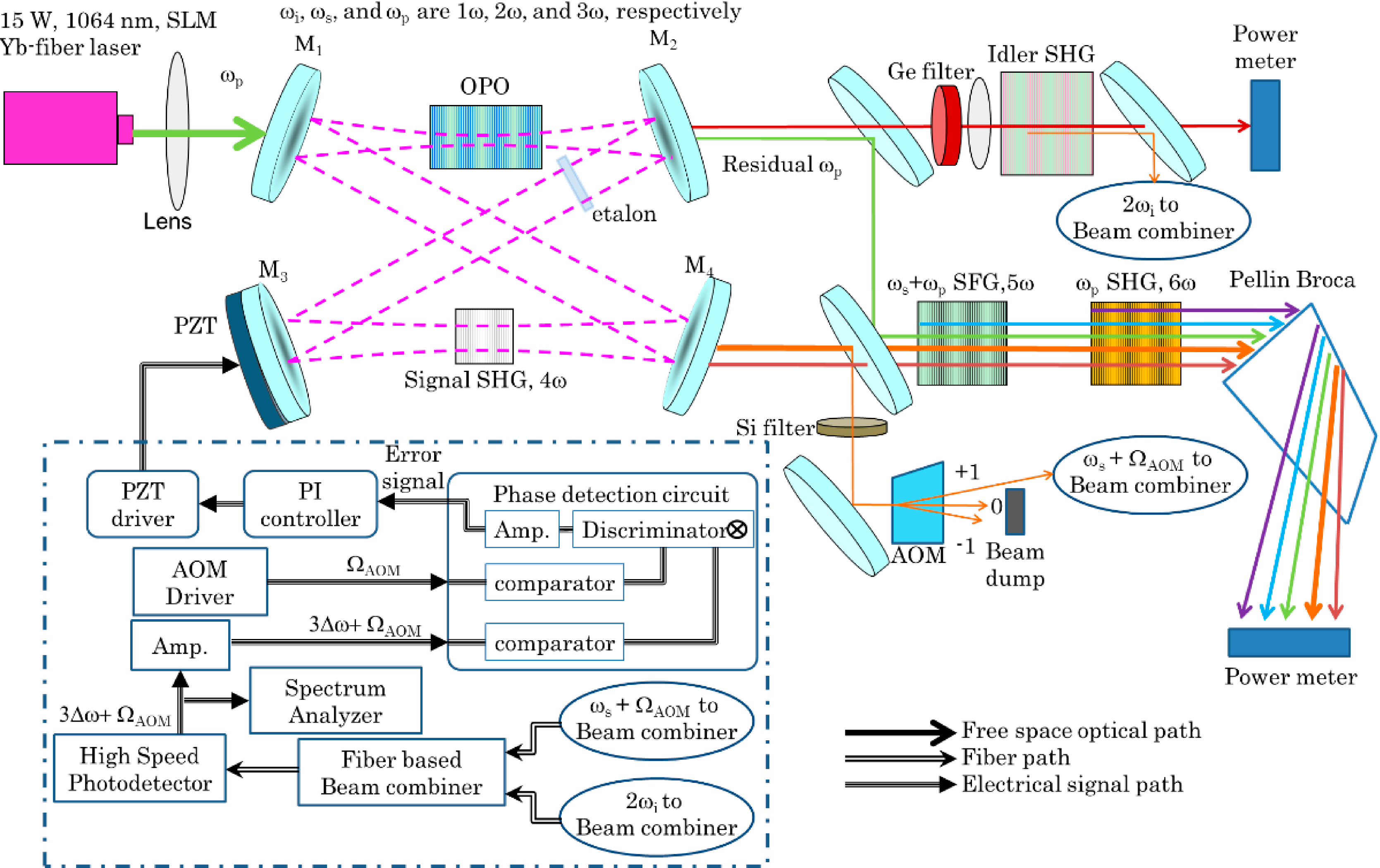
2. Experimental Section

The schematic of our multi-harmonic optical comb is shown in Figure 1. The watt-level frequency division-by-three singly resonant optical parametric oscillator (SRO) cavity is a bow-tie ring cavity consisting of two curved mirrors (M1 and M2) with a 100 mm radius of curvature, a flat mirror (M3), and an output coupler (M4). The OPO crystal is a 5 mol % MgO-doped PPLN crystal (from HC Photonics) with a length of 40 mm. The total cavity length is 500 mm. The pump, signal, and idler waves are designed to correspond to the 3rd harmonic wave, the 2nd harmonic wave, and the fundamental wave of a multi-harmonic optical comb. M1 and M2 have reflectance of <2%, >99.9%, and <5% at the pump, signal and idler wavelengths, respectively. M3 has reflectance of >99.9% at the signal wavelength. Output coupler mirror M4 has a 0.6% output coupling at the signal wavelength.
Figure 1. Multi-harmonic optical comb based on a frequency division-by-three singly resonant optical parametric oscillator. The optical parametric oscillator generates the fundamental wave (idler), the 2nd harmonic wave (signal), and the 3rd harmonic wave (pump) of the multi-harmonic optical comb. The 4th harmonic to 6th harmonic are generated by intracavity second harmonic generation (SHG), external cavity single-pass sum frequency generation (SFG), and external cavity single-pass SHG, respectively. The idler (the fundamental wave) SHG and a small portion of the 2nd harmonic wave are combined to produce an error signal for frequency control by tweaking the cavity length that is based on a home-made phase detection circuit, a commercial high-speed proportional integrating (PI) controller (New Focus LB1005) and a high voltage PZT driver (Physik Instruments E-501.621) shown inside the dashed box.
Applsci 04 00515 g001
The two end faces of the MgO:PPLN crystal are optically polished and antireflection-coated with <1%, <0.2%, and <5% reflectance at pump, signal, and idler wavelengths. The OPO crystal has a period of 30.8 µm and generates radiation at 1596-nm (signal) and at 3192-nm (idler) at 92.8 °C when pumped at 1064 nm. The pump laser is a cw linearly polarized, single-frequency Yb-doped fiber laser amplifier which is seeded by a single-mode mW-level DFB diode laser that has <0.1 MHz linewidth at 1064 nm from IPG Photonics. The pump laser is capable of producing ~15-W power with TEM00 mode and a M2 < 1.05. The cavity is designed to resonate at the signal wave that has a focusing parameter ξ = L/b of 1 (L is the crystal length and b is the confocal parameter). The pump beam is focused to a beam waist radius of 60 µm to mode-match to the cavity mode of the signal beam. The pump and idler exit the cavity from M2 and the signal output is at M4. The pump and idler are separated by a dichroic mirror for their power measurements. The idler wave is immediately focused into a 25 mm long MgO:PPLN crystal of period 34.25 µm for SHG of the idler to produce a beat signal with the signal wave. The purpose of the beat signal is to lock the length of the SRO cavity. This beat signal which is detected by a fast photodiode (EOT ET-3010) is sent to a cavity stabilization feedback circuit shown enclosed in the dash box in Figure 1. Locking the cavity length in turn fixes the wavelength of the signal to one of the cavity modes. A 250-µm thick intracavity fused silica etalon is inserted between M2 and M3 to maintain single-longitudinal-mode operation at high pump power.
The 4th harmonic to 6th harmonic waves can be generated by either intracavity or external cavity configurations. Intracavity frequency conversion could provide higher conversion efficiency, but the dynamic of the SRO cavity becomes more complicated and the cavity mirrors’ coatings are more susceptible to damage. So only the 4th harmonic comb component is generated by intracavity SHG from the 2nd harmonic wave (SRO signal wave). The nonlinear crystal for 4th harmonic wave generation is a 20.58 µm period MgO:PPLN crystal with a 10-mm length. The 5th and 6th harmonic waves are generated by single pass sum-frequency generation (SFG) of the 2nd harmonic wave and the 3rd harmonic wave (SRO signal and pump), and SHG of the 3rd harmonic wave (SRO pump) respectively. The specifications of these two nonlinear crystals are a 12.05 µm period MgO:PPLN crystal with 25 mm in length and a 7.97 µm period MgO:PPSLT crystal with 30 mm in length, respectively.

3. Results and Discussion

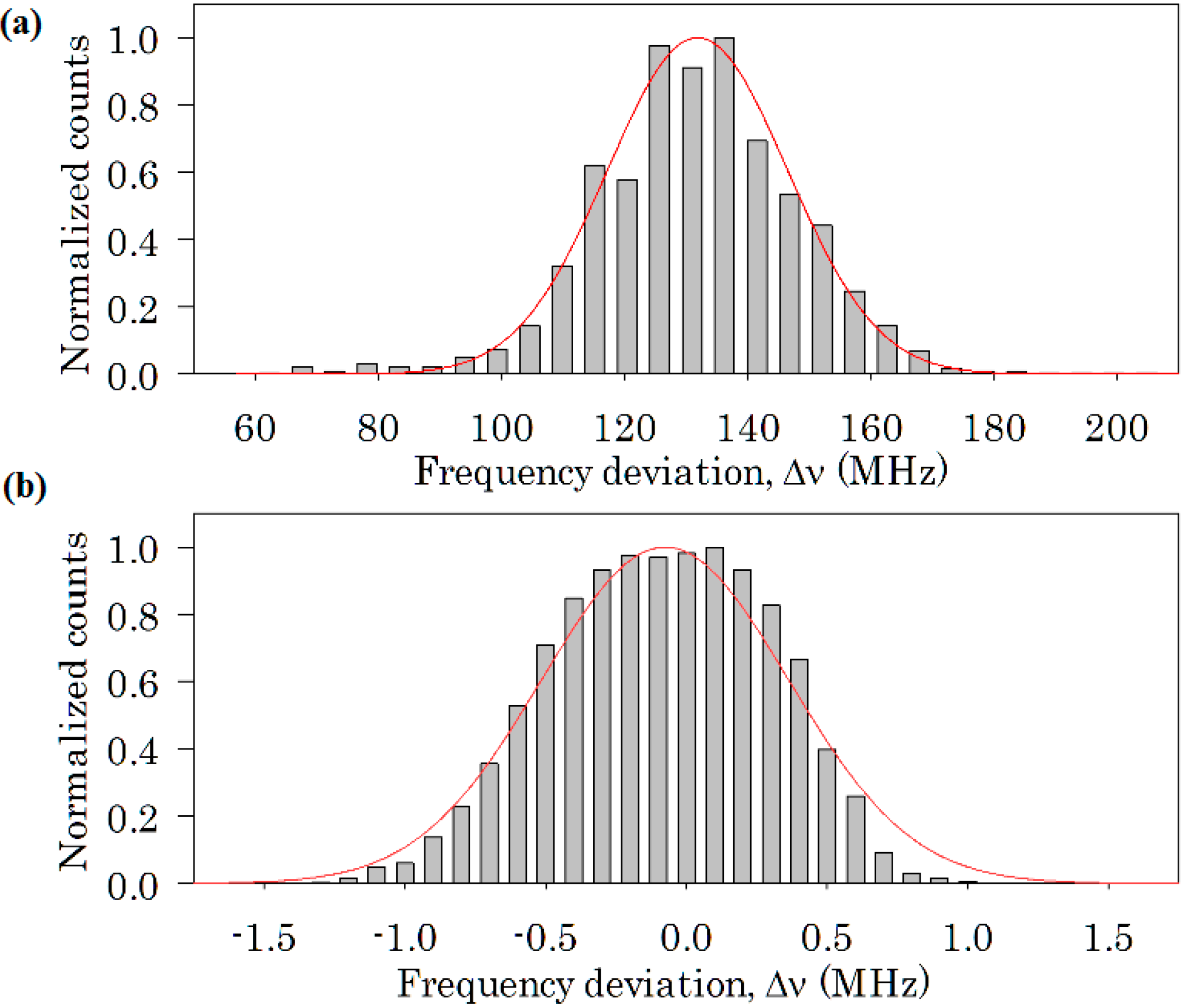
3.1. Frequency Control of Division-by-Three OPO

When the optical parametric oscillator is operating, the frequencies of signal and idler are 2ω + Δω and ω − Δω where Δω is the deviation in frequency from the fundamental (idler) of the exact division-by-three frequency of the SRO where the pump is at 3ω. Ideally Δω is to be equal to zero. For the SRO, zeroing Δω is done by adjusting the temperature of the gain crystal, the intracavity etalon, and the length of the cavity. The primary source of non-zero Δω is thermal and mechanical fluctuation of the SRO cavity length. Therefore it is necessary to track and stabilize the cavity length. Here a cavity stabilization feedback circuit is introduced to control the free spectral range of the SRO cavity to eliminate or minimize the frequency deviation. In our experiment, the frequency deviation is deduced from the interference beat signal between the frequency-doubled idler wave and the signal wave. This beat signal is equal to {2ω + Δω minus 2 × (ω − Δω)} to give 3Δω. According to standard practice in cavity stabilization, we give this beat signal an offset frequency ΩAOM of +54 MHz by passing the SRO signal beam through an acousto-optic modulator before mixing with the idler’s second harmonic. With this offset it is then possible to track the deviation Δω on both sides of Δω = 0 readily. The main ICs employed in our phase detection circuit are two ultrafast comparators (Analog Device AD96685), one phase discriminator (Analog Device AD9901) and one differential receiver amplifier (Analog Device AD8130). The error signal from our phase detection circuit is sent into the high-speed proportional integrating controller. Finally, the PZT driver adjusts a PZT (mounted on M3) in accordance to output from the proportional controller.
The quality of the stabilization control is monitored by recording the beat signal thus produced using a radio frequency (RF) spectrum analyzer (Rohde & Schwarz FSL3) with 100 kHz resolution bandwidth. The frequency of the recorded beat signal is 3Δω + ΩAOM. Histograms of the recorded frequency deviation over a 30 min period are shown in Figure 2 with and without cavity stabilization when the temperature of the OPO crystal was set to 92.8 °C to achieve phase-matching in the frequency division-by-three cw SRO. Figure 2a shows the frequency deviation, Δv = Δω/2π, without cavity stabilization. The recorded deviation Δω centers at 131.8 MHz with a ±14.7-MHz random drift (one standard deviation). With the stabilization circuit turned on, the frequency deviation is reduced to centering at −76 kHz with a ±437-kHz random drift. The solid red lines in Figure 2a,b are Gaussian fits of the distribution indicating that the source of the drifts are randomly distributed. The drift width in Figure 2b of 437 kHz is comparable to the frequency stability of the seed DFB diode laser of the fiber amplifier, implying that the seed laser’s drifts may be determining the width of the stabilized source. This result shows that by locking the seed laser to a stabilized reference-frequency comb linked to a primary frequency standard Δω can be reduced to less than one Hz and phase-stabilized eventually for waveform synthesis.
Figure 2. The histograms of frequency deviation from 30-min beat-wave signal recording by a radio frequency (RF) spectrum analyzer. The solid red line is fitting curve based on Gaussian distribution (a) without cavity stabilization. The frequency deviation centers at 131.8 MHz with a 14.7-MHz standard deviation; (b) with cavity stabilized feedback circuit functioning properly. The center is at −76 kHz with a 437-kHz standard deviation.
Applsci 04 00515 g002

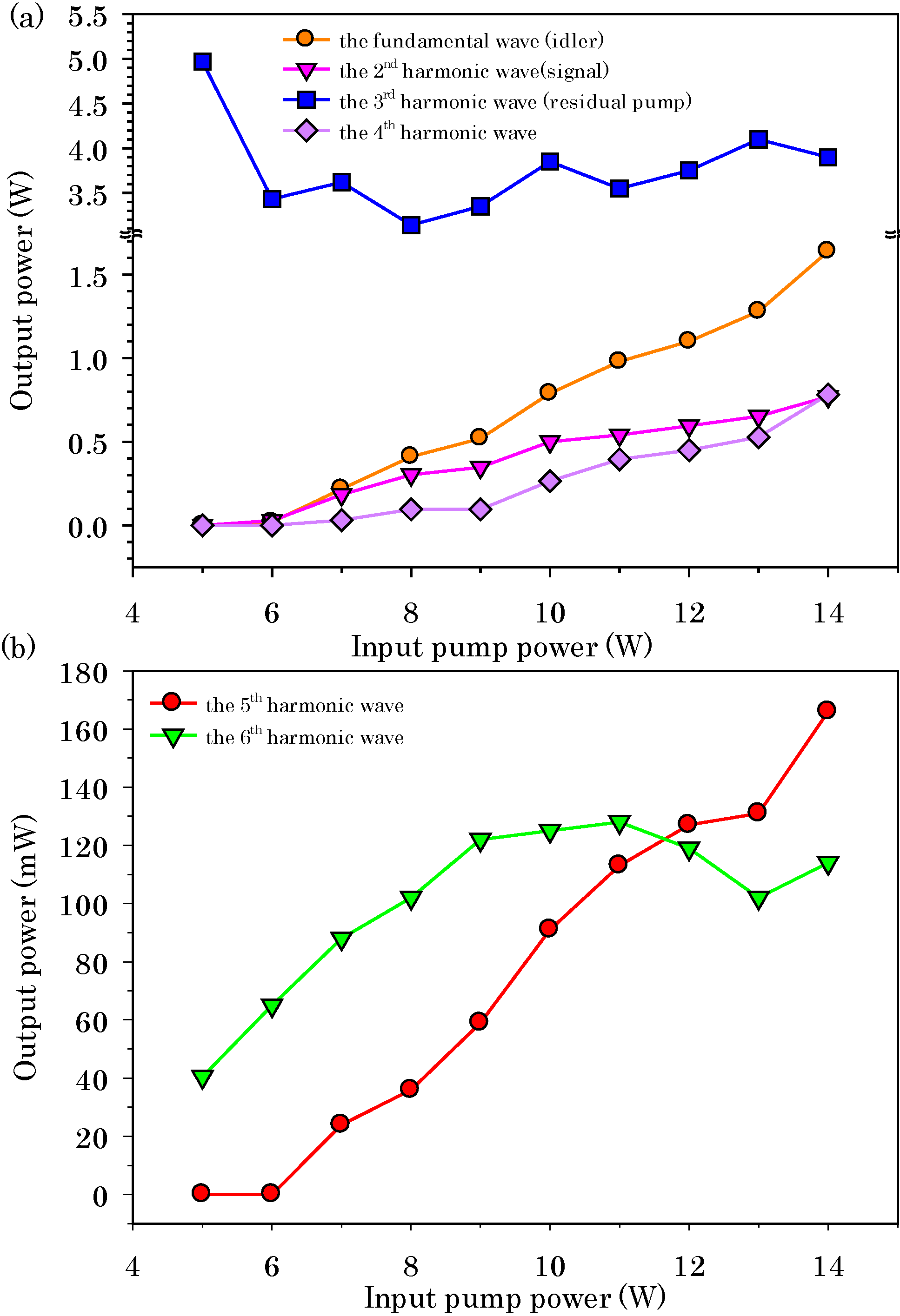
3.2. Power of Harmonic Comb Components

For a pump wavelength of 1064 nm, the generated harmonics are at 3192 nm, 1596 nm, 1064 nm, 798 nm, 638.4 nm, and 532 nm. Output power from the SRO and subsequent harmonics produced are measured with a broadband thermopile detector (Coherent P10). The idler power at 3192 nm is determined after its transmission through the SHG crystal and a dichroic mirror used to block out the second harmonic and any residual pump power. The third harmonic (residual pump) is combined with the second, fourth, fifth and sixth harmonics that are collinear after their generation. A Pellin Broca prism is used to disperse these harmonics before sending each into the power meter. The harmonics power is measured as a function of the input pump power. The results are shown in Figure 3.
Figure 3. The measured power of the multi-harmonic optical comb after Pellin Broca prism and the dichroic mirror after idler SHG in Figure 1. Here, (a) shows the power of the fundamental wave (idler), the 2nd harmonic wave (signal), the 3rd harmonic wave (residual pump power), and the 4th harmonic wave which were generated from the frequency divided-by-three SRO and the intracavity second harmonic generation for the 4th harmonic wave; (b) shows the power of 5th harmonic wave and the 6th harmonic wave. The 5th harmonic wave and the 6th harmonic wave are generated from single pass sum frequency generation and second harmonic generation, respectively.
Applsci 04 00515 g003
Figure 3a shows the power of the fundamental wave (idler), the 2nd harmonic wave (signal), the 3rd harmonic wave (residual pump power), and the 4th harmonic wave in the multi-harmonic optical comb. The SRO’s lasing threshold is at 6 W. This relatively high threshold is because the length of the SRO nonlinear crystal adopted in this experiment is shorter than used in previous experiments, and the insertion loss from the etalon and the intracavity SHG crystal. Without these extra optics, the SRO threshold drops to about 2 W. The maximum fundamental wave (idler), and the 2nd harmonic wave (signal) power are 1.64 W and 0.77 W, respectively at an input pump power of 14 W. The residual pump power (the 3rd harmonic wave) at this input is 3.9 W. For an output coupling of 0.6% the estimated circulating signal power in the cavity is as much as 128 W. This accounts for a respectable cw SHG conversion of the signal to the 4th harmonic which is measured to be 0.78 W without correcting for losses. The 5th harmonic and the 6th harmonic are obtained by single pass wavelength mixing. Figure 3b indicates the maximum powers obtained of the 5th harmonic wave and the 6th harmonic wave are 166 mW and 114 mW, respectively.
The power achieved for the frequency division-by-three SRO is at least ten times higher than previously reported in the literature [17]. This is the first time a cw harmonic comb of up to six harmonics has been reported. The total harmonic comb power of 7.4 W is unprecedented. High cw power is needed for effective phase and amplitude management of the comb components in waveform synthesis [19] and its subsequent applications. The multiwatt comb power that has been achieved is expected to be sufficient for this purpose.

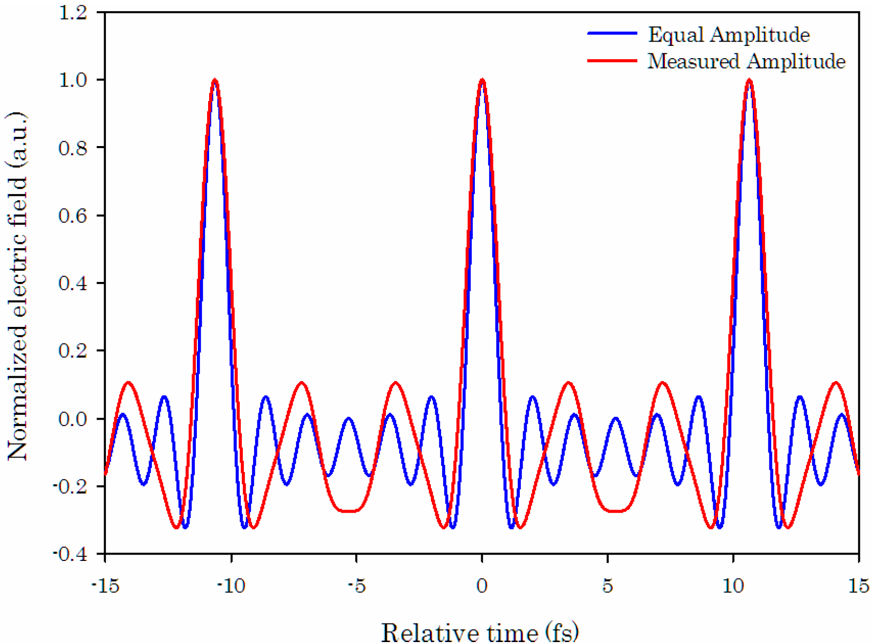
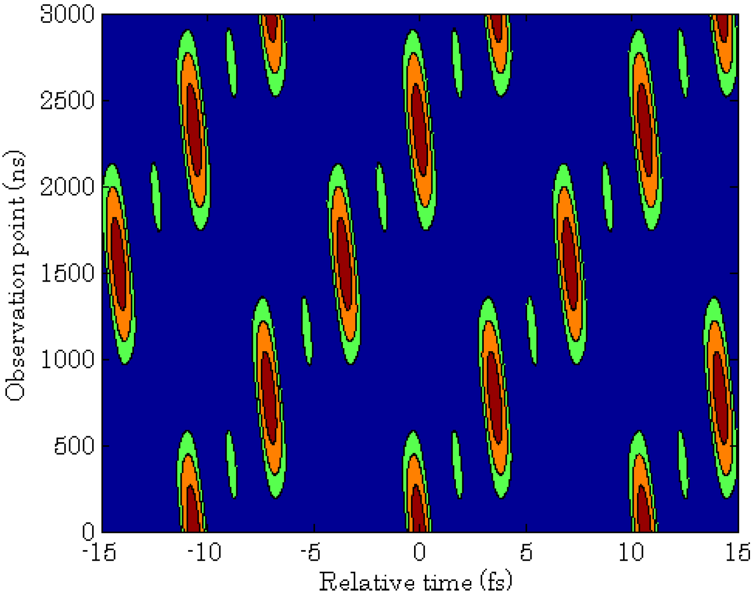
3.3. Simulated Waveform Synthesis with cw Harmonic Comb

The harmonic comb that is reported here has a fundamental wavelength of 3192 nm. The relative phase relationship of the harmonic comb is critical during waveforms synthesis. A fixed phase relationship in phase-matched three wave mixing process is ϕa = ϕb + ϕc − π/2, where subscripts a, b, and c represent the identities of the three optical waves [20]. Since all components of the cw harmonic comb in this work are generated from three wave mixing process; the deduced phase of ωn is ϕn = 1 − (n − 1)π/2, where ϕ1 = (ϕ3 + π)/3. In this harmonic comb, the phase of the pump, ϕ3 is the only unchangeable parameter in the system. The other components’ phase will follow the phase of pump based on the deduced relation. By managing the phase and amplitude of each comb component periodic field waveforms of arbitrary shape could be synthesized. The calculated repetition rate of the synthesized pulse train with this comb is ~94 THz, and has an equivalent period spacing of 10.6 fs. The shortest pulse synthesized within each period will be a transform-limited sub-cycle cosine pulse that has an electric field FWHM of 942 attoseconds. The FWHM of the intensity envelope of this cosine pulse is 1.59 fs. The simulated waveforms, synthesized with the comb produced in this experiment and when the spectral phases are adjusted to be equal, are plotted and shown as the red curve in Figure 4. By adjusting the amplitudes of the comb components to be equal, the narrowest pulses obtainable with this comb are plotted in blue in the figure.
For a comb produced with a perfect divided-by-three cw SRO this pulse train will be continuous. In reality the SRO is not perfect and there is a frequency deviation Δω as described in Section 3.1 above. The time duration in which the pulses in the train will remain intact is dependent on this frequency deviation Δω of the SRO. With Δω at one standard deviation of the present case the period of repetition of the pattern of synthesized pulses is ~2288 ns, corresponding to the time inverse of Δω of 437 kHz. Figure 5 shows the evolution of the synthesized waveform at this frequency deviation over a time span of 3000 ns, clearly indicating the pattern repeats itself every 2288 ns. Allowing for a drop of 10% in the maximum field strength as the criteria, then according to the numerical simulations, the sub-cycle cosine electric field maintains its strength for over 376 ns in every cycle. Since this is for a one standard deviation of the frequency deviation, 86% of the time this waveform has this shape for 376 ns or longer.
Figure 4. Synthesized waveforms calculated for the six component comb obtained in this experiment (red curve) and for the case where the components are reduced to equal amplitude (blue curve) for the zero detuning case. This will produce a continuous train of pulses of the calculated shape shown here.
Applsci 04 00515 g004
Figure 5. Numerical simulations of a subcycle cosine pulse electric field generated by this multi-harmonic optical comb with a frequency deviation of 437 kHz. The vertical scale is the time evolution of the pulse train from 0 to 3000 ns. The horizontal scale is the local time of the waveform displayed for about three cycles. The field pattern shifts with a phase shift of 2π/3 every 1/3 of a period by repeats and replicates itself in approximately 2288 ns which corresponds to the inverse of the frequency deviation used in the simulation. Normalized electric field strength shown here is color-coded to assist in recognition of the evolution of the field pattern as follows: dark red regions represent the value is from 0.8 to 1.0; orange regions represent the value is from 0.5 to 0.8; green regions represent the value is from 0.253 to 0.5 and blue regions represent the value is from 0.0 to 0.253.
Applsci 04 00515 g005
We pointed out in Section 3.1 that the residual frequency deviation is due to the drift of the seed laser. Hence we believe that this duration can be extended to over 1000 ns by actively stabilizing the seed laser of the pump in this experiment.

4. Conclusions

We have demonstrated a broadband cw multi-harmonic optical comb based on a frequency divided-by-three optical parametric oscillator. The frequency deviation is centered at −76 kHz with a fluctuation of 437-kHz in one standard deviation. According to our numerical simulation, a stable subcycle cosine electric field pulse can last for more than 376 ns at 437-kHz frequency deviation, which is two orders of magnitude longer than in any synthesizing schemes that have been reported. The output powers of the spectral components in this cw optical comb are 1.64 W, 0.77 W, 3.9 W, 0.78 W, 0.17 W, and 0.11 W which correspond to the fundamental wave to the 6th harmonics wave. The bandwidth of this multi-harmonic comb is ~470 THz. The results show that this cw multi-harmonic optical comb can be a useful light source of a stable optical waveform function generator.

Acknowledgments

We thank Shou-Tai Lin, Chia-Chen Hsu, Jin-Long Peng, Shang-Da Yang, Chen-Bin Huang, and Yuan-Yao Lin for helpful discussions. We acknowledge financial support by the Ministry of Science and Technology of Taiwan, Grants 101-2120-M-007-002, 101-2112-M-001-008, 101-2221-E-007-105 and 102-2221-E-007-111, the Academia Sinica of Taiwan, the Ministry of Education of Taiwan and the National Tsing Hua University.

Author Contributions

Drafting of manuscript: Yen-Yin Lin; Acquisition of data: Po-Shu Wu, Hsiu-Ru Yang; Analysis and interpretation of data: Po-Shu Wu, Hsiu-Ru Yang, Yen-Yin Lin; Critical revision: Yen-Yin Lin, A. H. Kung; Planning and supervision of the research: Yen-Yin Lin, Jow-Tsong Shy, A. H. Kung.

Conflicts of Interest

The authors declare no conflict of interest.

References

  1. Hänsch, T.W.; Walther, H. Laser Spectroscopy and Quantum Optics. Rev. Mod. Phys. 1999, 71, S242. [Google Scholar] [CrossRef]
  2. Hänsch, T.W. A Proposed Sub-Femtosecond Pulse Synthesizer Using Separate Phase-Locked Laser Oscillators. Opt. Commun. 1990, 80, 71–75. [Google Scholar] [CrossRef]
  3. Yavuz, D.D. Toward Synthesis of Arbitrary Optical Waveforms. Science 2011, 331, 1142–1143. [Google Scholar] [CrossRef] [PubMed]
  4. Chan, H.-S.; Hsieh, Z.-M.; Liang, W.-H.; Kung, A.H.; Lee, C.-K.; Lai, C.-J.; Pan, R.-P.; Peng, L.-H. Synthesis and Measurement of Ultrafast Waveforms from Five Discrete Optical Harmonics. Science 2011, 331, 1165–1168. [Google Scholar] [CrossRef] [PubMed]
  5. Goulielmakis, E.; Yakovlev, V.S.; Cavalieri, A.L.; Uiberacker, M.; Pervak, V.; Apolonski, A.; Kienberger, R.; Kleineberg, U.; Krausz, F. Attosecond Control and Measurements: Lightwave Electronics. Science 2007, 317, 769–775. [Google Scholar] [CrossRef] [PubMed]
  6. Serebryannikov, E.E.; Goulielmakis, E.; Zheltikov, A.M. Generation of Supercontinuum Compressible to Single-Cycle Pulse Widths in an Ionizing Gas. New J. Phys. 2008, 10, 093001. [Google Scholar] [CrossRef]
  7. Chin, S.L. Femtosecond Laser Filamentation; Springer-Verlag: New York, NY, USA, 2009. [Google Scholar]
  8. Harris, S.E.; Sokolov, A.V. Subfemtosecond Pulse Generation by Molecular Modulation. Phys. Rev. Lett. 1998, 81, 2894–2897. [Google Scholar] [CrossRef]
  9. Nazarkin, A.; Korn, G.; Wittman, M.; Elsaesser, T. Group-Velocity-Matched Interactions in Hollow Waveguide: Enhanced High-Order Raman Scattering by Impulsively Excited Molecular Vibrations. Phys. Rev. 2002, 65, 041802. [Google Scholar] [CrossRef]
  10. Kawano, H.; Hirakawa, Y.; Imasaka, T. Generation of More than 40 Rotational Raman Lines by 336 Picosecond and Femtosecond Ti:sapphire Laser for Fourier Synthesis. Appl. Phys. B Lasers Opt. 1997, 65, 1–4. [Google Scholar] [CrossRef]
  11. McCracken, R.A.; Sun, J.; Leburn, C.G.; Reid, D.T. Broadband Phase Coherence between an Ultrafast Laser and an OPO using Lock-to-Zero CEO Stabilization. Opt. Express 2012, 20, 16269–16274. [Google Scholar] [CrossRef]
  12. Huang, S.W.; Cirmi, G.; Moses, J.; Hong, K.H.; Bhardwaj, S.; Birge, J.R.; Chen, L.J.; Li, E.; Eggleton, B.J.; Cerullo, G.; et al. High-Energy Pulse Synthesis with Sub-Cycle Waveform Control for Strong-Field Physics. Nat. Photonics 2011, 5, 475–479. [Google Scholar] [CrossRef]
  13. Wirth, A.; Hassan, M.T.; Grguraš, I.; Gagnon, J.; Moulet, A.; Luu, T.T.; Pabst, S.; Santra, R.; Alahmed, Z.A.; Azzeer, A.M.; et al. Synthesized light transients. Science 2011, 334, 195–200. [Google Scholar] [CrossRef] [PubMed]
  14. Manzoni, C.; Huang, S.W.; Cirmi, G.; Farinello, P.; Moses, J.; Kärtner, F.X.; Cerullo, G. Coherent synthesis of ultra-broadband optical parametric amplifiers. Opt. Lett. 2012, 37, 1880–1882. [Google Scholar] [CrossRef] [PubMed]
  15. Green, J.T.; Weber, J.J.; Yavuz, D.D. Continuous-Wave Light Modulation at Molecular Frequencies. Phys. Rev. 2010, 82, 011805. [Google Scholar] [CrossRef]
  16. Ulvila, V.; Phillips, C.R.; Halonen, L.; Vainio, M. Frequency Comb Generation by a Continuous-Wave-Pumped Optical Parametric Oscillator Based on Cascading Quadratic Nonlinearities. Opt. Lett. 2013, 38, 4281–4284. [Google Scholar] [CrossRef] [PubMed]
  17. Douillet, A.; Zondy, J.-J.; Santarelli, G.; Makdissi, A.; Clairon, A. A Phase-Locked Frequency Divide-by-3 Optical Parametric Oscillator. IEEE Tran. Instrum. Meas. 2001, 50, 548–551. [Google Scholar] [CrossRef]
  18. Lee, D.-H.; Klein, M.E.; Meyn, J.-P.; Richard, W.R.; Gross, P.; Boller, K.-J. Phase-Coherent All-Optical Frequency Division by Three. Phys. Rev. 2003, 67, 013808. [Google Scholar] [CrossRef]
  19. Hsieh, Z.-M.; Lai, C.-J.; Chan, H.-S.; Wu, S.-Y.; Lee, C.-K.; Chen, W.-J.; Pan, C.-L.; Yee, F.-G.; Kung, A.H. Controlling the Carrier-Envelope Phase of Raman-Generated Periodic Waveforms. Phys. Rev. Lett. 2009, 102, 213902. [Google Scholar] [CrossRef] [PubMed]
  20. Armstrong, J.A.; Bloembergen, N.; Ducuing, J.; Pershan, P.S. Interactions between light waves in a nonlinear dielectric. Phys. Rev. 1962, 127, 1918–1939. [Google Scholar] [CrossRef]

