
Combined Operation of Electrical Loads, Air Conditioning and Photovoltaic-Battery Systems in Smart Houses


1
Dept. Industrial Engineering, University of Salerno, Fisciano (SA) 84084, Italy
2
Dept. Management & Innovation Systems, University of Salerno, Fisciano (SA) 84084, Italy
*
Author to whom correspondence should be addressed.
Appl. Sci. 2017, 7(5), 525; https://0-doi-org.brum.beds.ac.uk/10.3390/app7050525
Submission received: 11 April 2017
/
Revised: 9 May 2017
/
Accepted: 11 May 2017
/
Published: 18 May 2017
(This article belongs to the Special Issue Smart Home and Energy Management Systems)
Abstract
:In this paper, a novel Energy Management System (EMS) is proposed for a hybrid energy system with photovoltaic (PV) and energy storage system for a smart house. The EMS is designed to control the shiftable loads, the air conditioning and the electric storage system. The aim is to reduce the electrical energy consumption cost without compromising the end-user comfort. Monte Carlo Simulation (MCS) is used to estimate the optimal size of the hybrid system considering energy saving and investment costs. Simulations results confirm the effectiveness of the proposed EMS in decreasing the electrical energy consumption and costs. The proposed method for the sizing of the hybrid system is also able to select the best size of the PV-battery system in smart houses.
1. Introduction
Sizing of Distributed Generation (DG), Energy Storage Systems (ESSs), Smart house holds applications, and Demand Response (DR) strategies are all widely discussed issues, and analyzed in a large number of recent studies [1]. With reference to these areas, several studies address the problem of residential energy management. New challenges are emerging due to increasing photovoltaic (PV) generation, so that Energy Storage Systems (ESS) with distributed PV generators have been developed in different papers. However, a high diffusion of PV may cause critical issues (voltage rise) in a distribution system, thus different coordinated control systems are proposed [2,3].
In order to minimize electricity customer cost, the management of power flow becomes a fundamental issue. In [4], an energy management system for a grid-connected PV-battery hybrid system is proposed, so that customers can benefit of demand response and a control method is developed to schedule the power flow.
Numerous works evaluate these problems in terms of “micro-grid systems”. In [5], some design considerations are presented for distributed micro-storage systems in residential applications. In this paper, the term “micro-storage” refers to small residential energy storage units with a capacity of few kilowatt-hours, and different micro-storage system architectures as well as analysis of system sizing are discussed.
Other authors propose a DC micro-grid with a multilayer control and smart grid communications [6]. The control design permits a better DC micro-grid integration by avoiding undesired injection, mitigating fluctuations in the power grid and reducing grid peak consumption.
Some studies focus on the characteristics of the converters in the micro-grid systems with the aim of improving the conversion efficiency. In [7], a hybrid system consisting of a PV array and rechargeable battery integrated to the distribution grid is presented. The system performs load sharing with the distribution grid by controlling the voltage source inverter (VSI), the boost and the buck-boost converters. The cost–benefits problem of solar PV technology is analyzed in [8,9]. In [8], the authors propose a system with given PV modules and EES based on bank capacities to solve the daily energy flow control problem. Furthermore, in order to facilitate intensive penetration of PV production into the grid, a method is proposed in [9]. Peak shaving is realized with the minimal cost and power fluctuations on the grid are reduced by using a power supervisor based on a predictive power scheduling algorithm. A basic analysis study of stand-alone solar PV micro-grid power system is presented in [10]. The system is designed on the basis of residential load profile and solar exposure level in a particular area. In order to improve the integration of PV and energy storage systems, a power management strategy is designed to manage power flows between PV systems and an ultra-capacitor (UC) [11].
A numerical model that computes an optimized capacity of energy consumption is proposed in [12]. This model is based on weekly forecast with the aim of providing a stable energy that is insulated from the instability of weather change. The system is able to increase the energy consumption in normal days while maintaining minimum stable energy in bad weather conditions.
To increase the use of PV energy in the residential applications, some researchers suggest a control of power flow and a selection of MPPT parameters for grid-connected PV systems with battery storage [13]. Other works discuss these issues in terms of innovative converter features for PV-battery systems [14]; a reconfigurable solar converter (RSC) is presented to perform dc/ac and dc/dc operations, by using a single-stage three phase grid-tie solar PV converter.
A control method for the power electronic converters is discussed in [15]: the potential of utilizing battery energy storage for participating in primary frequency regulation of the grid is investigated. The charging/discharging rate of the battery is controlled based on the frequency droop characteristic. In [16], the authors propose a power transfer strategy (PTS) by which, through a specific EMS, output fluctuation of renewable energy, load demand, state of the grid, peak load period and state of charge (SOC) of the battery are taken into account to effectively operate the grid-connected hybrid system.
Numerous models are developed by considering multiple sources of power [17,18,19]. Sizing of components in distributed renewable energy systems are analyzed in [17], while in [18,19], methods that regulate the power generation units and the energy storage are proposed, with reference to the state of energy storage. In these studies, PV/Wind/Battery systems are considered. In [19], particularly, a Hybrid Power System (HPS) for residential applications is analyzed. The system is characterized by two PV panels inclined in two different directions, one Wind Generation System (WGS) and Battery Storage (BS) connected to a DC bus and then to the AC side through pulse width modulation inverter.
In addition to the solar-batteries technology, an efficient residential Energy Management System has to consider Demand Response (DR) potential. DR encourages the interaction and responsiveness of the customers by offering a broad range of benefits on system operation and on market efficiency. In [20,21,22,23,24,25,26,27,28,29,30,31,32], these issues are analyzed and different solutions are proposed, with particular reference to the benefits in a smart grid and to the market efficiency.
A probabilistic methodology for evaluating the impact of residential DR choices is proposed, by using a combination of Monte Carlo Simulation (MCS) and Real Time (RT) distribution market simulation based on Distribution Locational Marginal Price (D-LMPs) in [20,25]. Real-time pricing (RTP) at the residential level is considered in combination with small-scale Distributed Generation (DG), in order to suggest an energy scheduling solution [23]. In [26,30,31], electrical and thermal appliances are jointly scheduled, considering the residents’ consumption behavior, seasonal probability and other aspects. The economic aspects related to the installation of distributed energy storage systems designed to reduce the electricity cost for a customer-side application, are discussed in [32], by considering flexible electricity tariffs. In these works, the economic benefits of matching the load demand to power supply are evaluated; furthermore, objectives like peak shaving and reduction of energy costs are focused with the aim of not harming the comfort of residents. The aim of this paper is to highlight, based on the literature described above, the features that an efficient energy management system must have in order to optimize the aspects of cost saving, comfort and efficient utilization of renewable sources and storage systems. To this end, the proposed system develops, in an innovative way, the simultaneous management of the shiftable loads, the storage of electric power and the PV system considering the real-time price acquisition.
2. Modeling of the System
2.1. Modeling of the Energy Management System
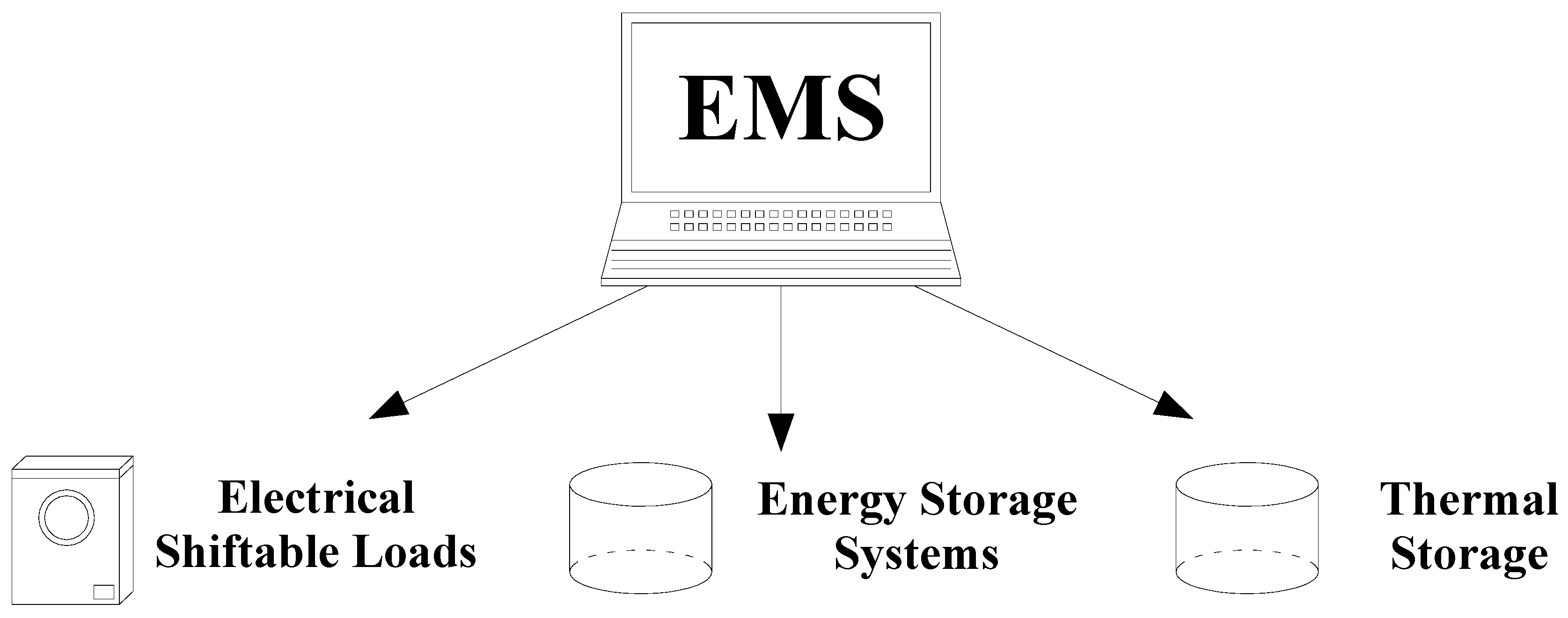
In this paper, an Energy Management System (EMS) is developed, with the aim of managing the electric power demand of a residential user (Smart-Home). The objective is to optimize the use of electric power produced on site from renewable sources, by assuming a rational behavior of end-users and by considering energy cost variations in the distribution energy market. The EMS considers a PV generation and an energy storage system (battery). Concerning the mode of operation, the control is based on different main aspects, as in the following list and as shown in Figure 1:
- Control of shiftable loads;
- Control of the air conditioning (thermal storage);
- Control of the electric storage system.
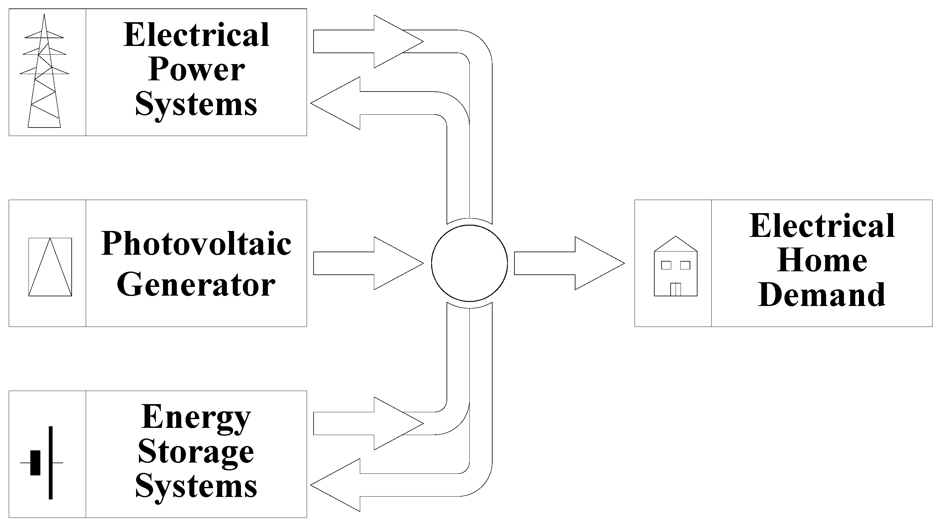
To obtain a complete and effective management of the devices in a smart-home, an ICT infrastructure is an essential requirement allowing the EMS to communicate with devices in order to vary the user power demand. The EMS control logic selects the energy source and establishes the energy flow as shown in Figure 2. As regards the AC-DC coupling, different system configurations are possible, for example [5,7,13,14,15].
EMS output signals have the following functions:
- Enable controllable devices, such as shiftable loads and air conditioning, thus modifying their power demand; and
- Absorb the necessary amount of power from available sources to guarantee the energy requirements of the households.
EMS input signals provide information on the operational state of the devices; at the same time, load power demand and environmental variables, such as temperature, lighting and presence of people are monitored. Furthermore, signals from the user interface named Human Interface Device (HID) can be acquired in order to satisfy the end-user needs and preferences, regarding the mode of operation of the system. In particular, the input data can be classified as:
- External to the Smart-Home, such as energy price, and outdoor temperature;
- Internal to the Smart-Home, such as indoor temperature, presence of people, and State Of Charge (SOC) of the energy storage system;
- Data from a local generation system: PV production;
- Data set by the end-user: temperature set-point, priority list of programmable electrical loads, and presence of not programmable electrical loads.
Air conditioning, shiftable loads, PV generator and energy storage system are all controlled by a specific logic implemented according to designed mathematical model of computation based on state machines. The EMS is designed by using a state machine method and implemented using Matlab-Stateflow. The model considers the following implemented functions:
- Shiftable loads;
- Battery storage charging and selection of energy sources; and
- Thermal storage of electrical PV energy.
The objective of the shiftable loads function is to plan the use of shiftable loads in order to minimize their energy cost [24,26]. The decision about the period of operation related to shiftable loads requires the knowledge of the following information: the list of priorities by which the user requests the operation; the electric characteristics such as absorbed electrical power and operating time; the hourly price of the energy that will be purchased and absorbed from the grid.
As regards with the battery storage charging and selection of energy sources, the designed model involves the use of the storage system to mainly feed the air conditioning system. The control system managing the storage system ensures the real time compliance with the battery characteristics and the technical constraints, also related to the state of charge (SOC) limits [9,23]. The control logic enables the charging or discharging of the energy storage system by considering the energy consumption of the air conditioning system, the availability of energy from the PV system, the price of energy from the grid, the available power from the grid, and the value of the SOC.
As regards the thermal storage, the electrical power absorbed by the air conditioning system is normally taken from the grid. The electrical power to the air conditioning system is directly provided from the PV generator when it generates energy. It may be necessary to feed, at the same time, the air conditioning system from both the grid and the PV generator or, in another operation mode, to feed it from both the battery and the PV generator. Alternative to the electrical grid, in some cases, it may be more convenient to absorb the necessary energy only by the energy storage system.
2.2. Modeling of the Smart House with the Photovoltaic-Battery Systems
A thermal model of the smart-home is considered, able to calculate the electric energy required by air conditioning [26]. In consideration of the operating mode (summer or winter) and of the temperature set point chosen by the user, the control system adjusts the electrical power necessary for the air conditioning system so that the temperature inside the house reaches the desired value.
In view of the widespread penetration of PV systems as part of distributed generation in a smart-home, it is assumed the presence of a PV generation. The production of the PV system, as known, depends on many factors, some of which are related to the constructive characteristics and to the type and place of installation; other factors, such as weather conditions, may be considered as random variables [2,9]. In the used model, these stochastic variables are used to properly model the PV production, evaluated through the data pattern detected by the Joint Research Centre (JRC) in Ispra (Italy). This method allows treating the PV generator as a random variable in the implementation of the Monte Carlo Simulation (MCS).
The electrical Energy Storage System (ESS) is connected to the air conditioning system and it is rechargeable both from the PV generator and from the grid. The characteristics of the storage system are determined basing on the configurations that optimize the overall cost of the energy consumption in the smart-home. Five possible sizes of storage capacity are considered: from 4 kWh to 8 kWh in steps of 1 kWh. Charging and discharging of the battery are controlled by EMS, taking into account the cost of energy from the grid, the power availability of PV system and the current SOC. The ESS model, in terms of power and storage capacity, is designed considering the current technologies of the batteries. In fact, the stored or delivered energy depends on the maximum (SOCmax) and minimum (SOCmin) charge level; consequently, the SOC is continuously monitored. In addition, in this model, to different structural characteristics it corresponds a different cost of investment.
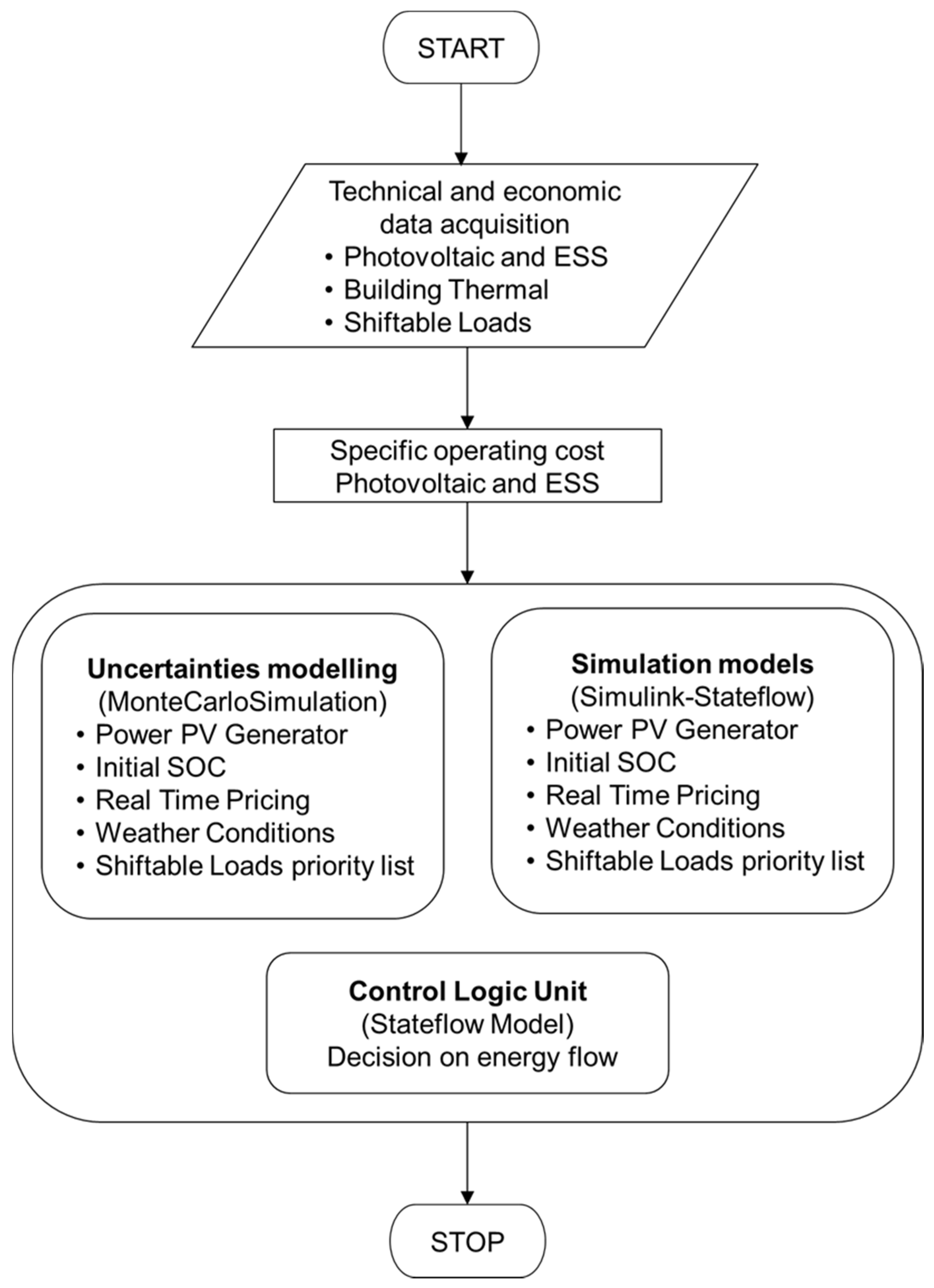
The EMS’s overall operation can be synthesized through a flowchart to make the strategy of the proposed study more straightforward. The description of the algorithm can be exemplified by the following steps, as also shown in Figure 3.
- 1.
- Data Acquisition
- -
- PV Generator: technical characteristics and initial investment;
- -
- Energy Storage System (ESS): technical characteristics and initial investment;
- -
- Building thermal characteristics; and
- -
- Shiftable Loads.
- 2.
- Calculation of the specific operating cost of the PV-battery hybrid system.This parameter allows deciding if it is more convenient to use the PV system or the grid to charge the battery. It also determines whether it is best, inside the smart-house, to absorb energy from the PV system or from the battery rather than to absorb it from the grid.
- 3.
- Monte Carlo Simulation
- -
- Generating stochastic variables: PV-Power, Initial SOC, Real Time Pricing, and Weather Conditions; and
- -
- Simulation of Simulink and Stateflow models: economic, thermal, PV and ESS, control logic.
- 4.
- Output results: energy and cost values.
The model for the calculation of the economic parameters such as Total Savings Cost (TSC) and Discontinued Payback Period (DPP) is then developed. The innovative proposed control logic considers the ability to manage the available energy sources, both electrically and thermally, in order to change the demand by optimizing the Total Saving Cost (TSC). To this end, the control logic is able to control the energy flows by allowing different combinations of available energy sources and by giving priority to the most economically advantageous one. The EMS, taking into account the comparison between the real-time tariff (related to energy absorbed from the grid) and the specific cost of the PV-battery hybrid system, decides among the following:
- -
- Feeding the electrical loads from the grid, from PV system or ESS. If the first power source is not enough, the EMS also decides to use the next one so that the balance between the power required by the loads and the power supplied by the electric sources is respected.
- -
- Charging the battery through the grid or the PV system;
- -
- Saving the excess energy produced by the PV system, transforming it into thermal energy and storing it as thermal storage by changing the temperature set point, which implies an increase in the power absorbed by the air conditioning system;
- -
- Returning the thermal energy stored in the smart-house: this action implies a reduction in the power absorbed by the air conditioning system; and
- -
- Injecting to the grid the excess energy from the PV system.
3. Economic Model
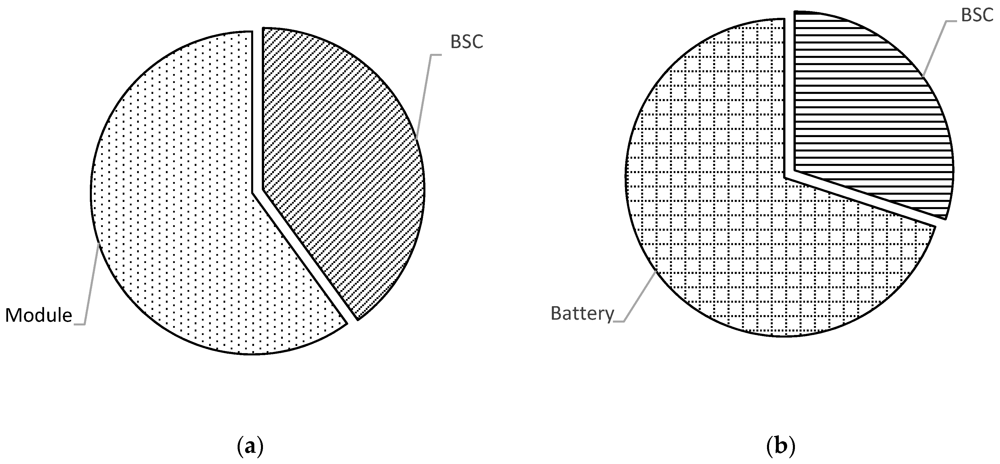
The EMS takes into account the different cost items related to the energy storage system, the PV system, and energy bought and sold in the electricity market [32]. The cost of the energy storage system (CESS) is modeled by considering two components. The first one, the Balance of System Cost (CBSC), is a function of the characteristics of the power electronics components, drivers and control logic for battery charge/discharge but it does not take into account the capacity of the battery. The second component is a cost that depends directly on the battery storage capacity (CBat).
The total cost is defined as follows:
The cost of the PV Generator (CPVG) is a function of the installed power and depends on the following factors: the number of PV modules; the installation cost of the modules on the roof; the inverter cost; and inclusive of the control logic. As in the previous case, these cost items can be divided into Balance of System Cost (CBSC) and PV Modules cost (CPVM) as follows:
The hardware cost for the EMS system control logic is included in BSC costs of the storage system and PV generator. The cost of the electricity absorbed from the grid (CEGrid) is calculated by considering a time-variable rate with 15-minute intervals as follows:
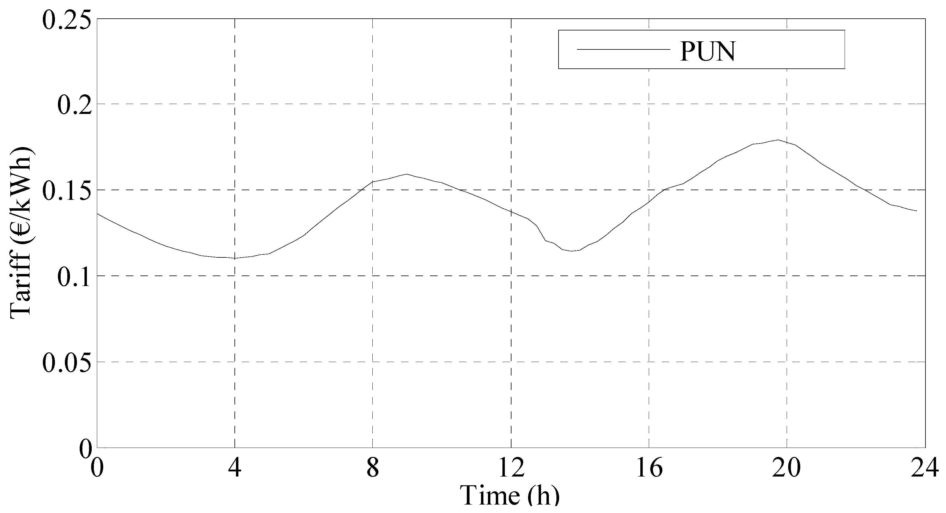
The case of the Italian Power Exchange (IPEx) is considered, with particular reference to the “Mercato del Giorno Prima” (day ahead auction market) and to the “Prezzo Unico Nazionale” (PUN), i.e., the National Single Price during the year 2015 as shown in Figure 4.
In this market, the accepted demand bids related to consuming units belonging to Italian geographical zones, are valued at the PUN; this price is equal to the average of the prices of the geographical zones, weighted for the quantities purchased in those zones. The end user can buy the energy through a market participant that realizes its profits by selling energy at a higher price considering a price plus fee. The total price of the acquired energy considers the use of the national electricity grid both for the services provided by the Distribution System Operator (DSO) and for those provided by the Transmission System Operator (TSO), in addition to state taxes.
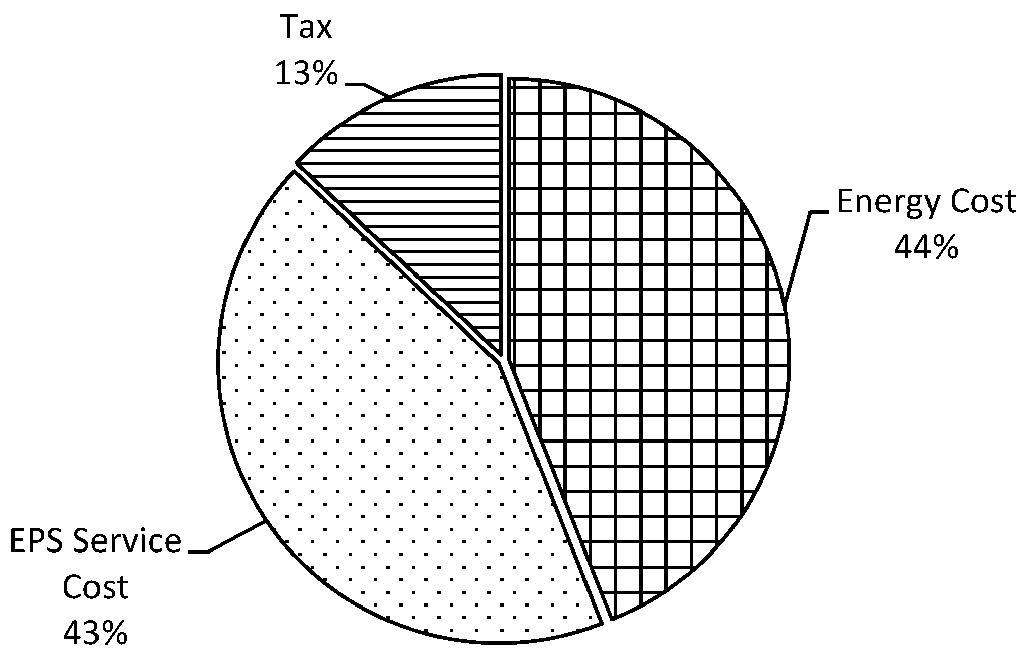
In summary, and by simplifying the complex structure of the Italian electricity bill, for a typical residential user, the cost of electrical energy consists of different parts, generally contributing as follows to the electricity bill, as also shown in Figure 5:
- 44% electrical power from the grid (CEGrid);
- 43% electricity power system services by DSO and TSO (CPSS); and
- 13% government taxes (Tax).
In addition to the cost of electricity from the grid (CEGrid), the cost components related to the services of the electrical distribution system (CPSS) are analytically calculated and expressed as a total cost of power system services as:
For each energy range EGrid, there is a certain value of CPSS. Then, the total cost of energy from the grid is shown in Equation (5):
Figure 6 shows the hardware cost considered in the Economic Model.
The energy fed by the PV system into the grid (ESSP) is sold to the DSO, and is regulated by the Authority “Autorità per l’Energia Elettrica, il Gas e il Sistema Idrico” (AEEGSI, Electricity, Gas and Water System Regulator) through a sale contract called “Scambio Sul Posto” (SSP, Net Metering Service). The electricity sold remuneration (PSSP) is determined through a sale rate (TSSP), based on the values applied for 2015:
4. Simulation Results
To validate the effectiveness of the implemented control functions, a comparative analysis is made by considering a reference case study, characterized by the presence of fixed and variable loads, as well as of the air conditioning system, and without local distributed generation and energy storage systems. Simulations are performed to determine the consumption of electrical energy and the associated costs; in particular, in the MCS, stochastic variables are independently generated until the convergence of consumption and costs.
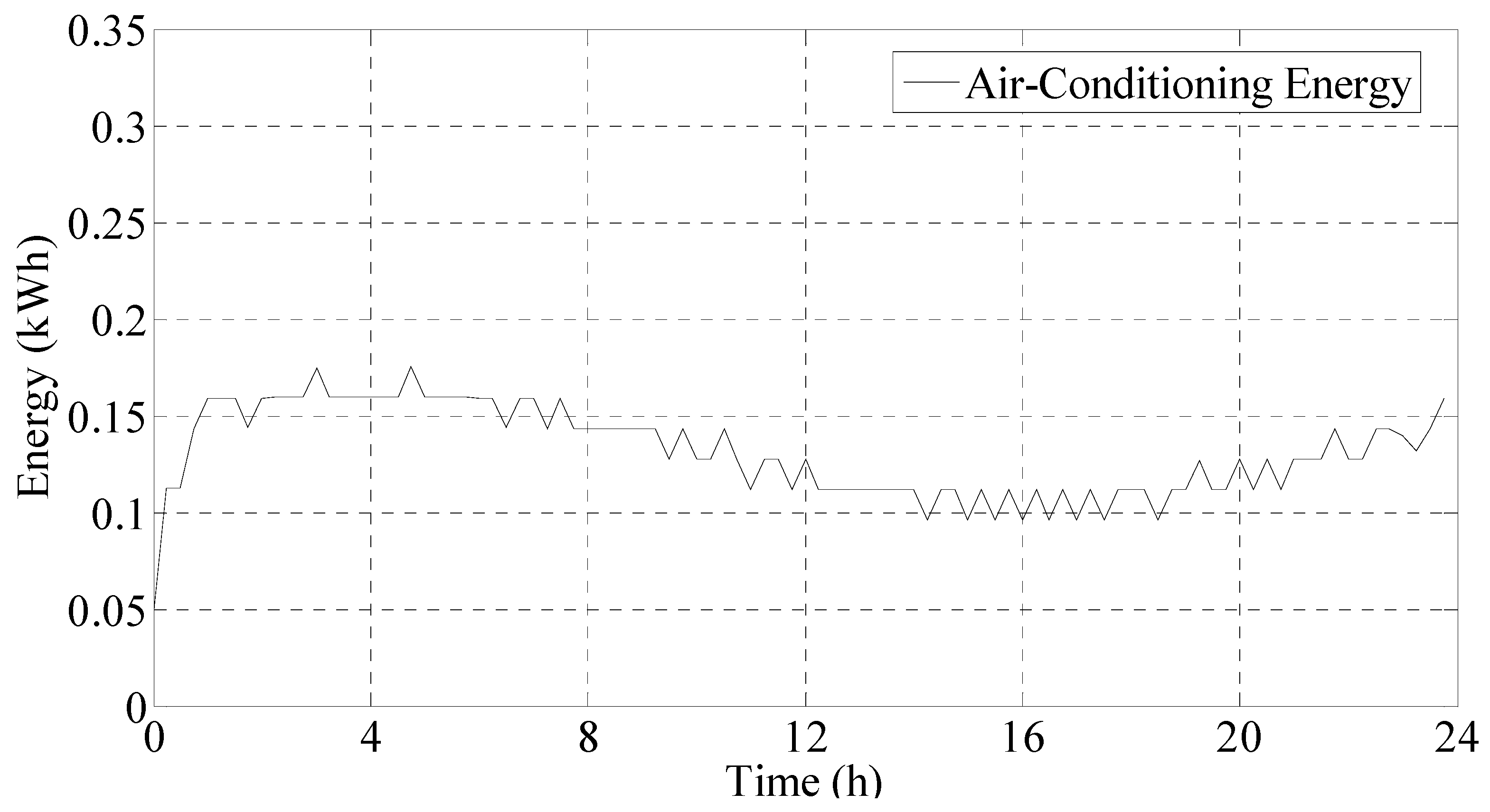
Some of the simulation results are shown in the following figures. The case study is analyzed in a generic winter day, characterized by an assigned energy required by the conditioning system, shown in Figure 7, and by some electrical appliances.
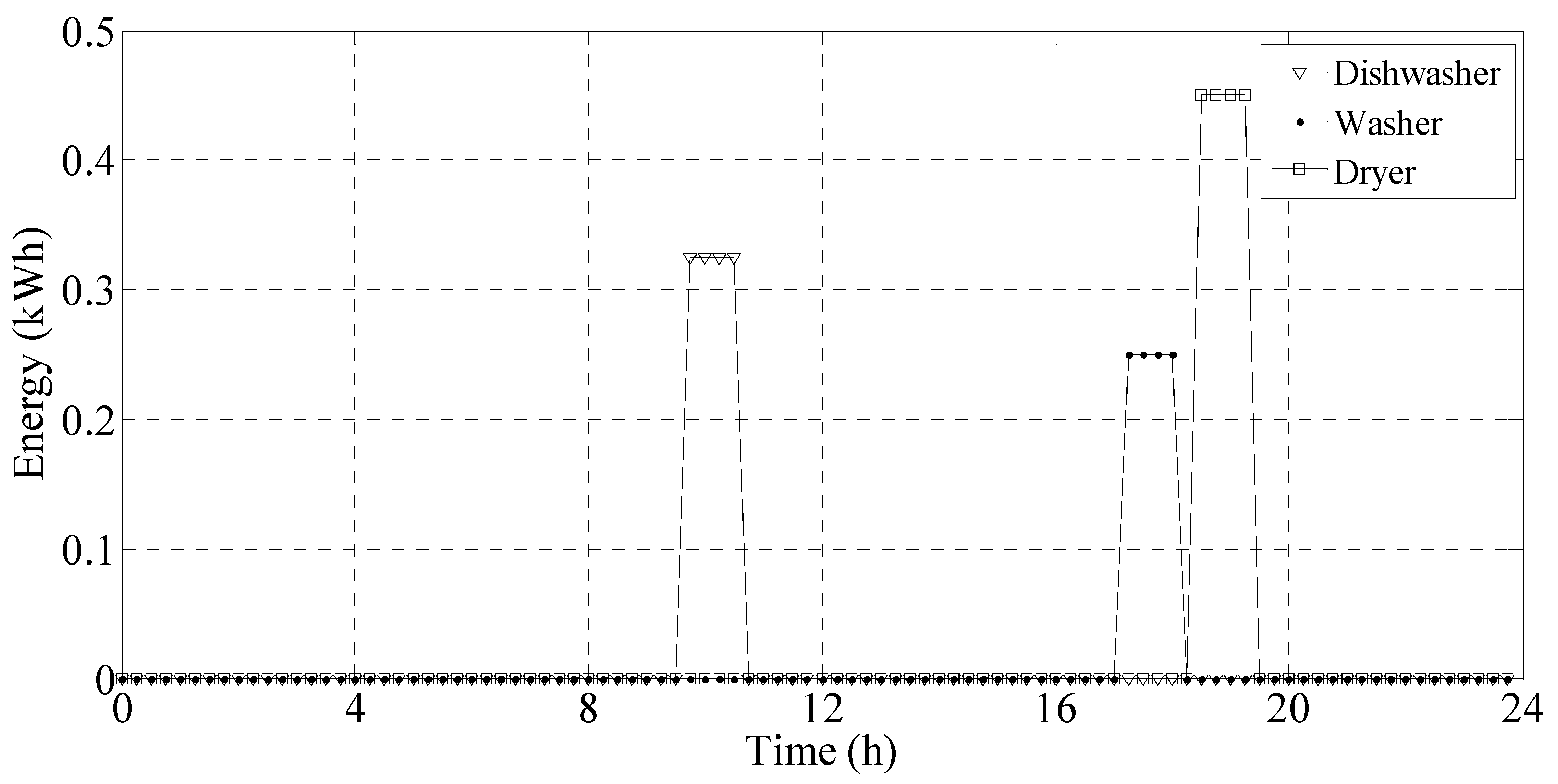
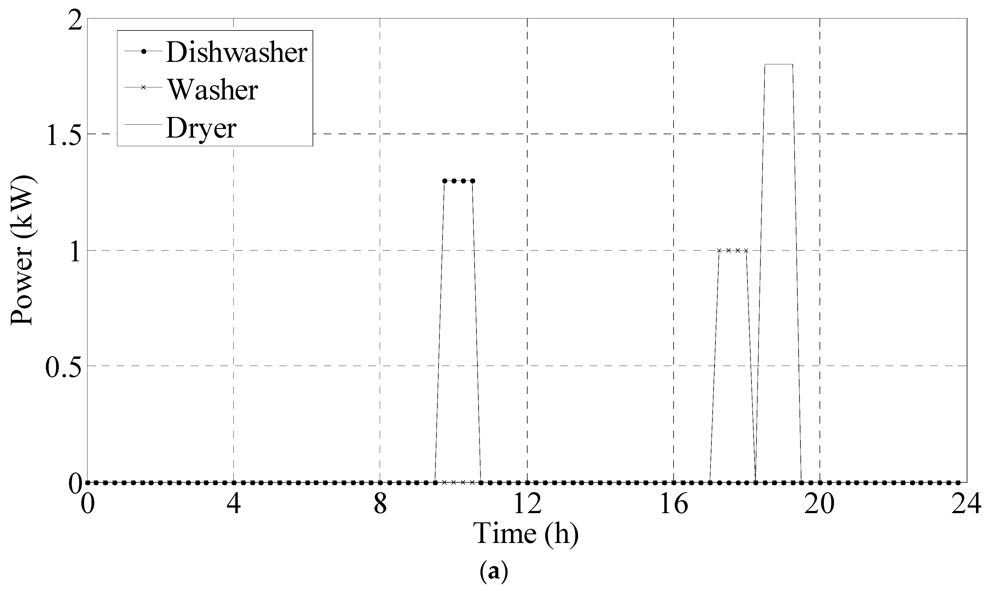
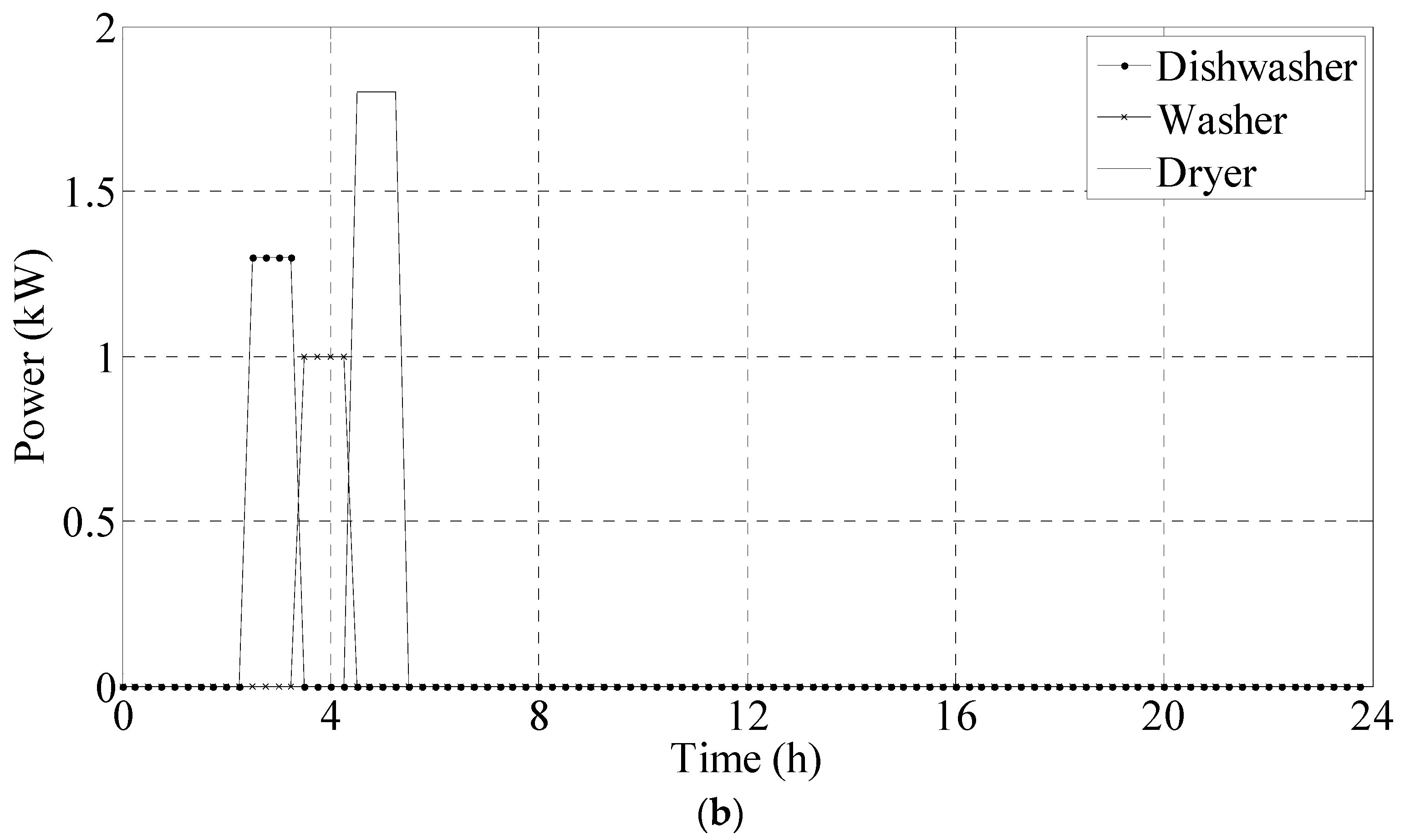
The appliances considered in the simulation are dishwasher, washing machine and dryer, as shown in Figure 8. They have precise characteristics of power consumption and operating time. The sequence and time of their use are determined by user’s choice.
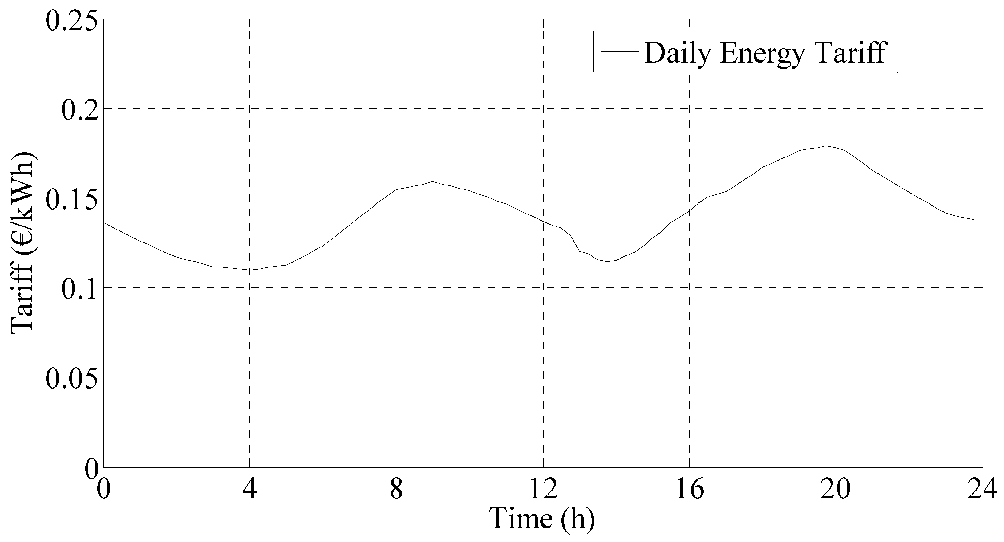
The electricity cost (CEGrid) is calculated considering an energy real time tariff (TEGrid) [21,22] for domestic use, derived from the Italian electricity market in 2015, as shown in Figure 9.
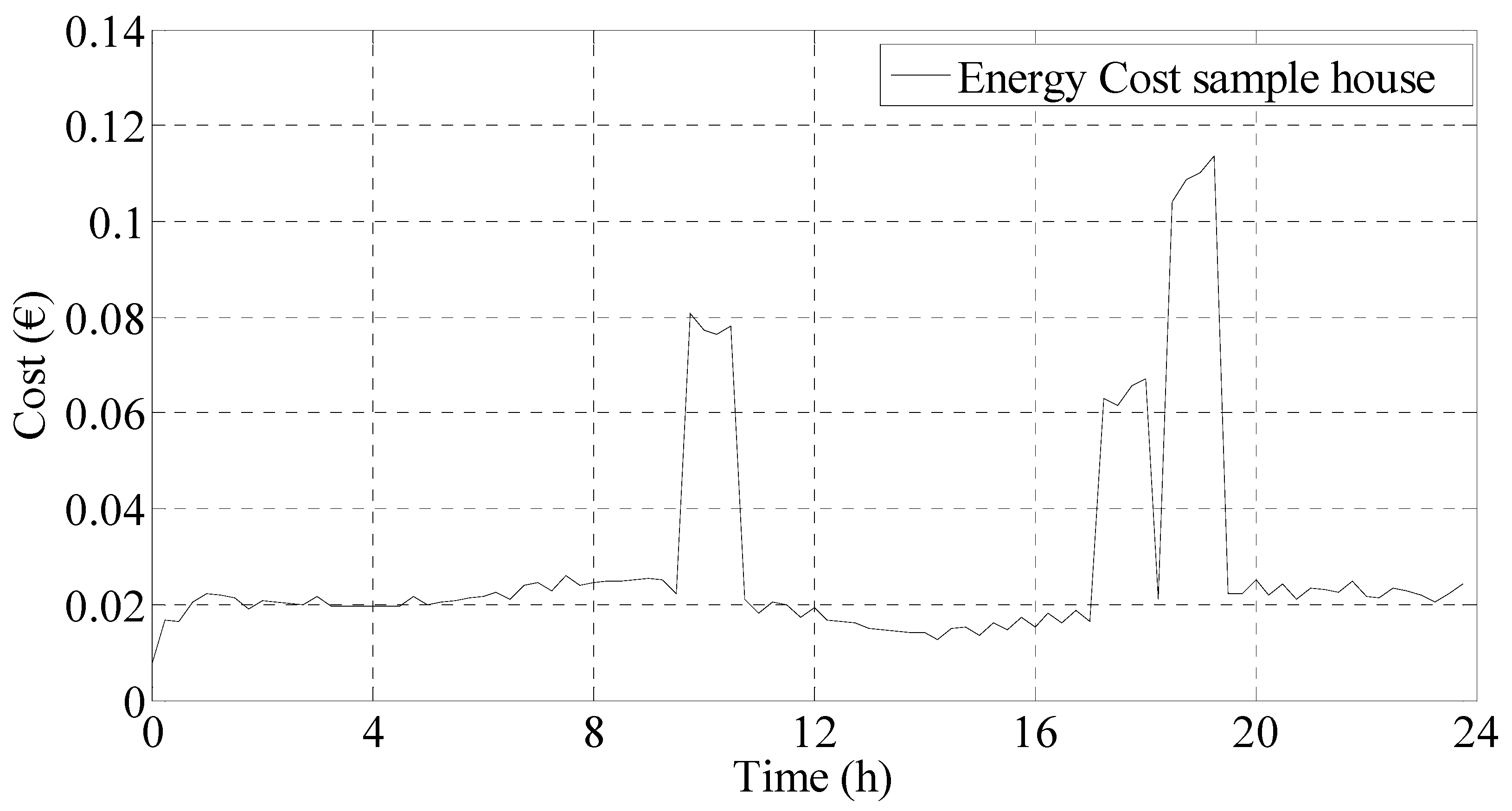
The total daily cost CEGrid (CGrid without grid-dependent additional cost components) is shown in Figure 10.
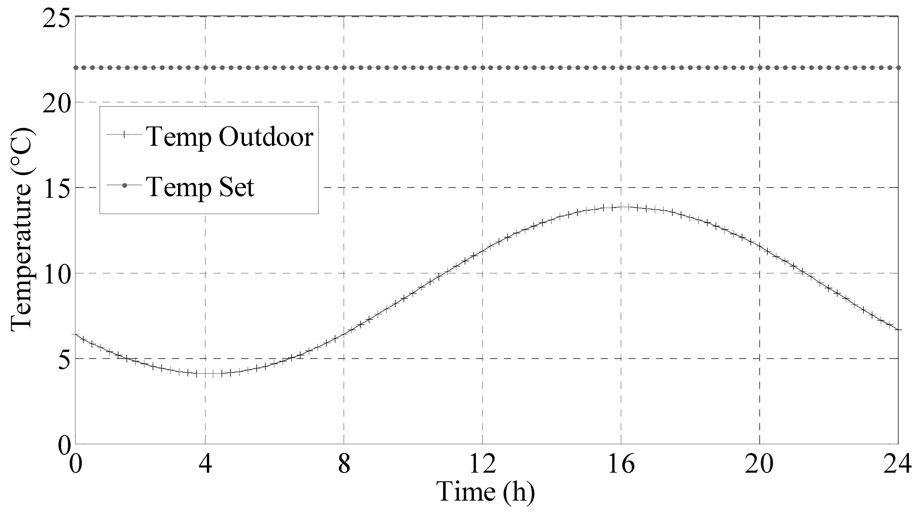
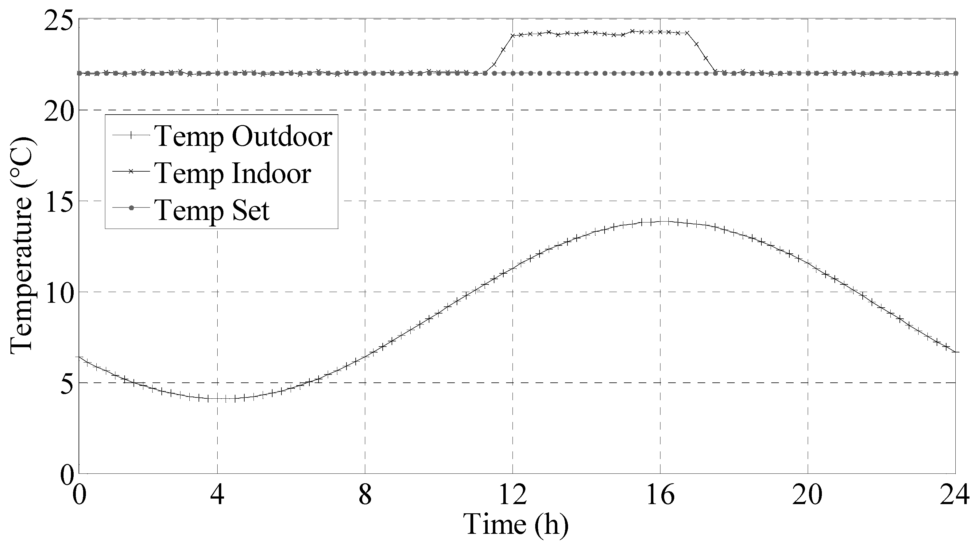
In this case, the user’s preferences are crucial for the operation of the air conditioner; in fact, the desired value of the internal temperature has been assumed equal to 22 °C, while the outside temperature varies as shown in Figure 11.
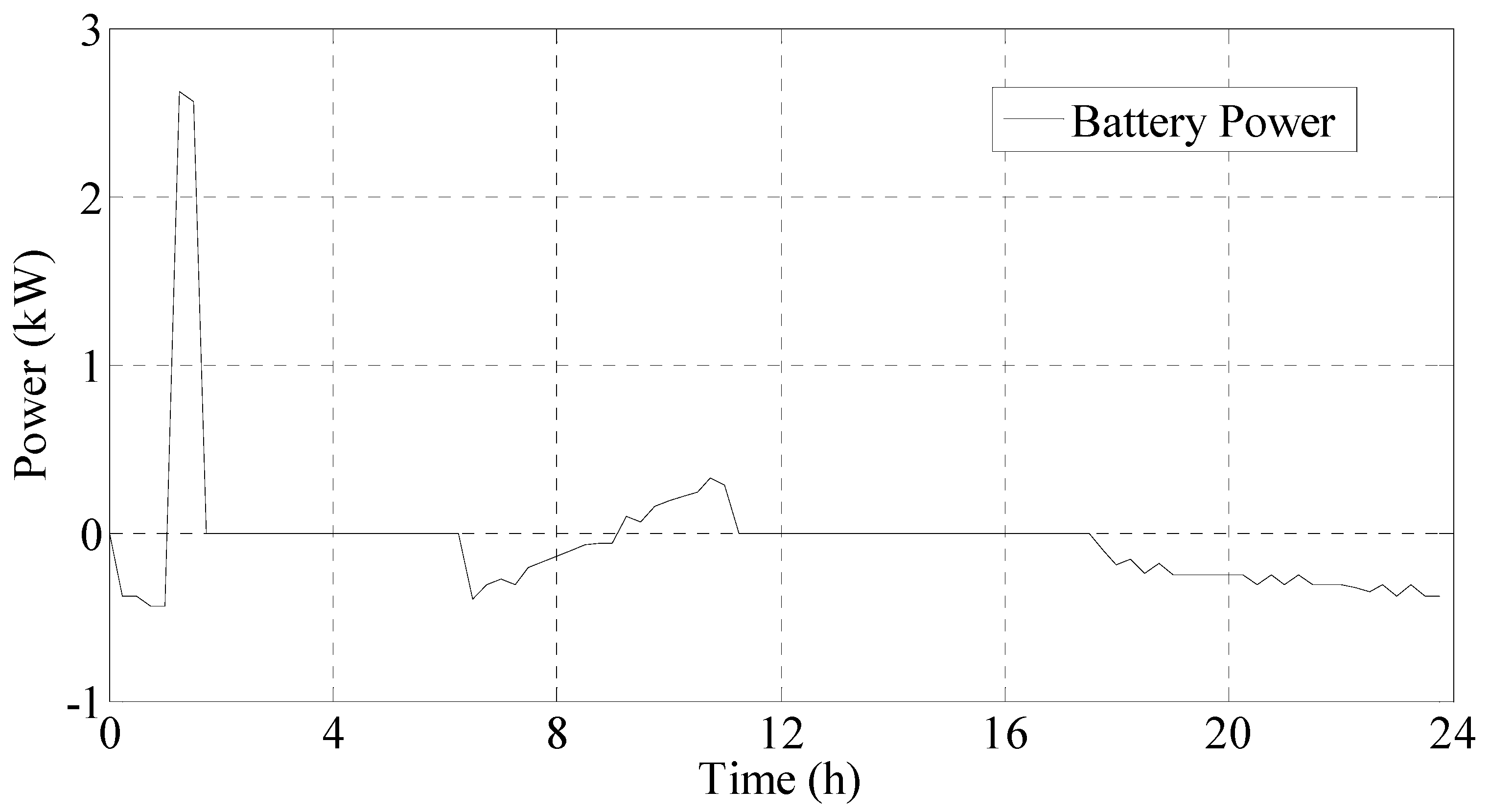
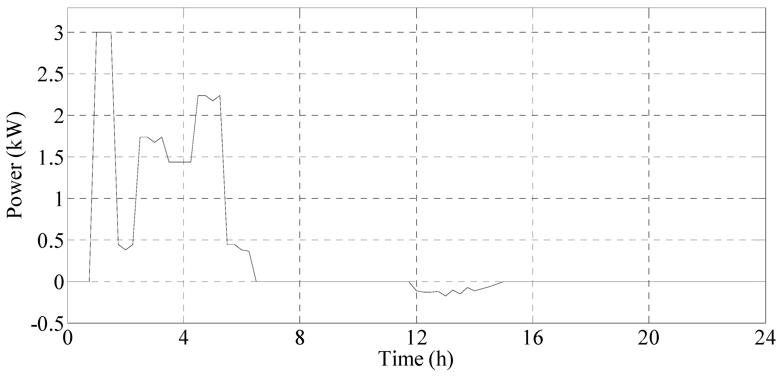
The battery control unit continuously works and the EMS decides if the storage system can be enabled to work as load (as state of re-charging) or as a generator. When the storage system is re-charged, it absorbs energy from the grid or from the PV generator (see Figure 13).
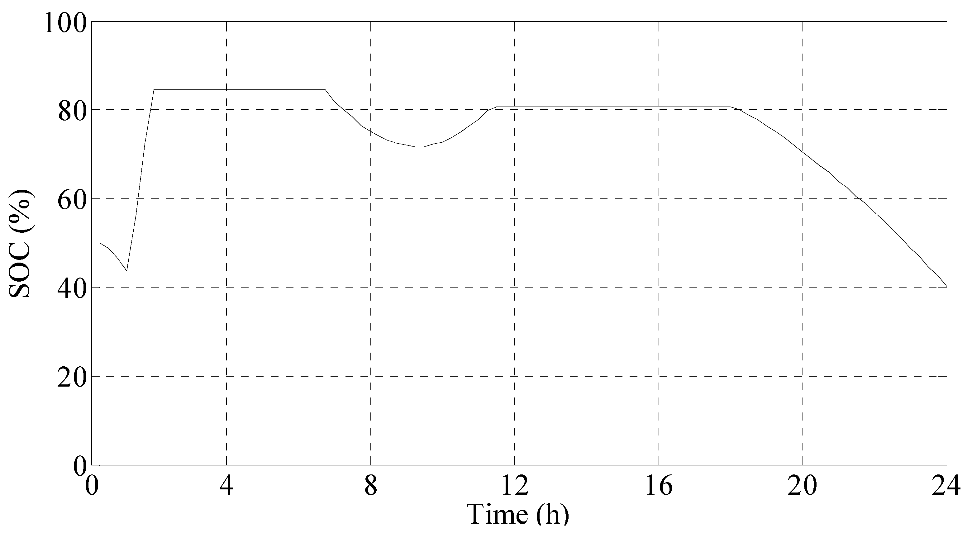
During the re-charging, if the energy is absorbed from the grid the EMS also performs a control action to constrain the maximum power consumption for residential users according to the contractual limit (typically 3 kW). Furthermore, the EMS monitors the State Of Charge (SOC) of the energy storage system to ensure the limit of the operating conditions such as the maximum and minimum charge level (for example SOCmin = 20% and SOCmax = 80%). To guarantee a long battery life, the system is dimensioned to perform one charge–discharge cycle per day (Figure 14).
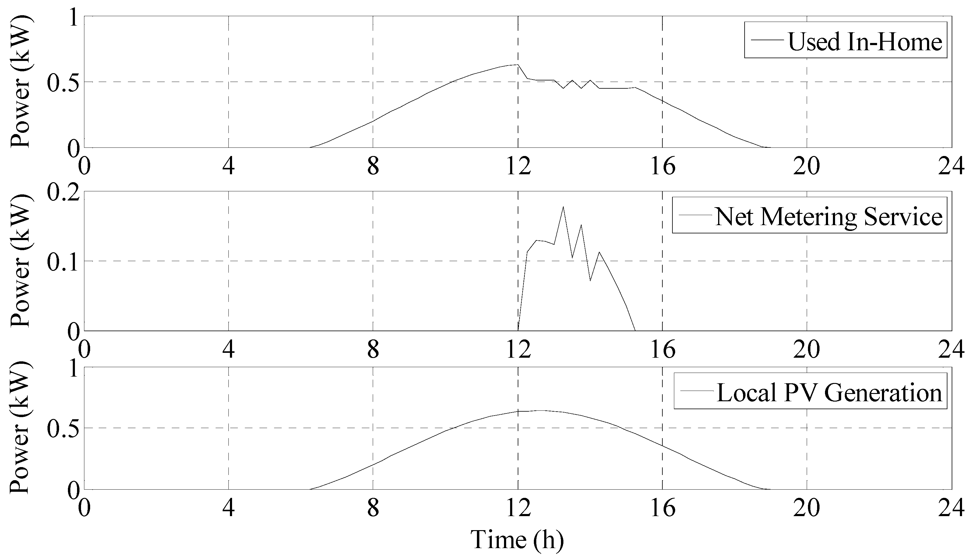
The PV generation is used to feed the electrical loads as well as to re-charge the battery. In some cases, the PV generation can exceed the amount of the maximum allowable electrical energy demand consisting of the local electrical energy demand, the battery storage capability and the thermal storage capability of the house. In this case, the EMS allows the PV Generator injecting electrical power into the grid as shown in Figure 15. This energy is sold under the contract “Net Metering Service”.
The use of the energy produced by the PV generator is optimized by the EMS with the purpose of minimize the energy costs. This amount of energy is mainly used by the local electrical loads or stored in the battery [1].
With the battery charged, the EMS control logic enables the function “thermal storage” by controlling the temperature set point (Temp Set), as shown in Figure 16. The house behaves as a reservoir for thermal energy in a measure dependent on the thermal characteristics of the building materials.
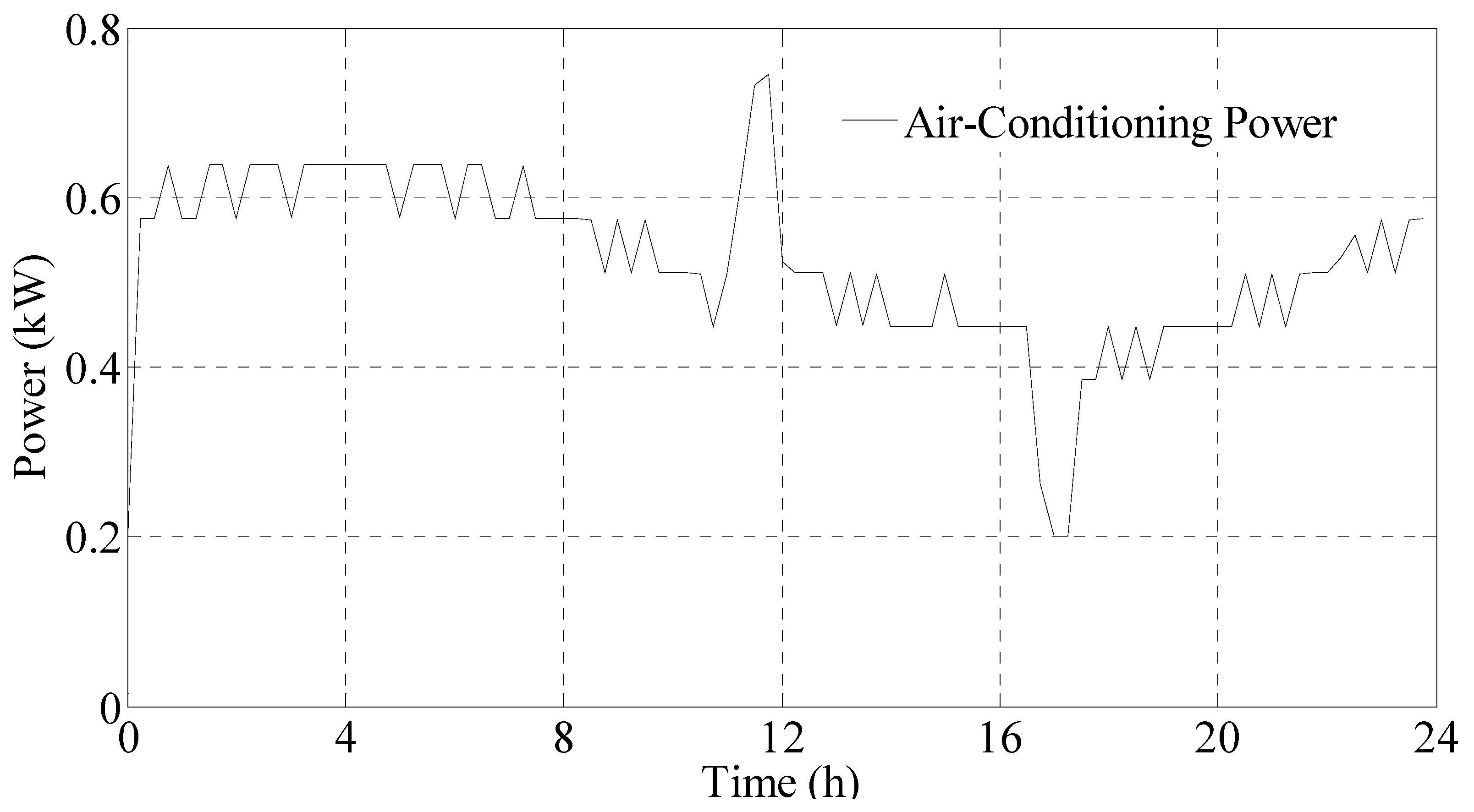
The “Thermal Storage” function adjusts the air conditioning system operating mode, by changing of its electricity demand, as shown in Figure 17.
The energy profile of the house is thus modified by the EMS as well as with the allocation of “shiftable loads” at times when the cost of electric energy is lower. Figure 18 shows the total electric power absorbed/injected from/to the grid during the day.
It is worth noting that the overall electricity demand decreases and a surplus of the energy generated by the PV system is injected into the grid only during the peak of PV power production.
In a standard configuration, without considering the EMS, the PV Generator and the storage system, the electrical energy demand of the house is equal to 11.48 kWh/day, and is all provided by the grid. Considering the presence of the EMS, a PV generator of 1 kWp and an energy storage system of 4 kWh, the electric power absorbed from the grid is equal to 8.35 kWh/day, with an energy saving of 3.13 kWh. Moreover, 0.32 kWh are injected into the grid.
To evaluate the benefits of the EMS, the Monte Carlo Simulation method is applied [26]. Specific function generators are designed to simulate the non-deterministic variables, in particular:
- Energy real time price;
- Outdoor temperature;
- Initial indoor temperature;
- Set-point temperature;
- Initial State Of Charge (SOC); and
- PV electrical energy production.
Five possible levels of storage capacity are considered, from 4 kWh to 8 kWh in steps of 1 kWh, and these can be combined with two possible sizes of the PV generator: 1 kWp or 2 kWp. For each specific configuration of the PV-battery hybrid system, many simulations are performed.
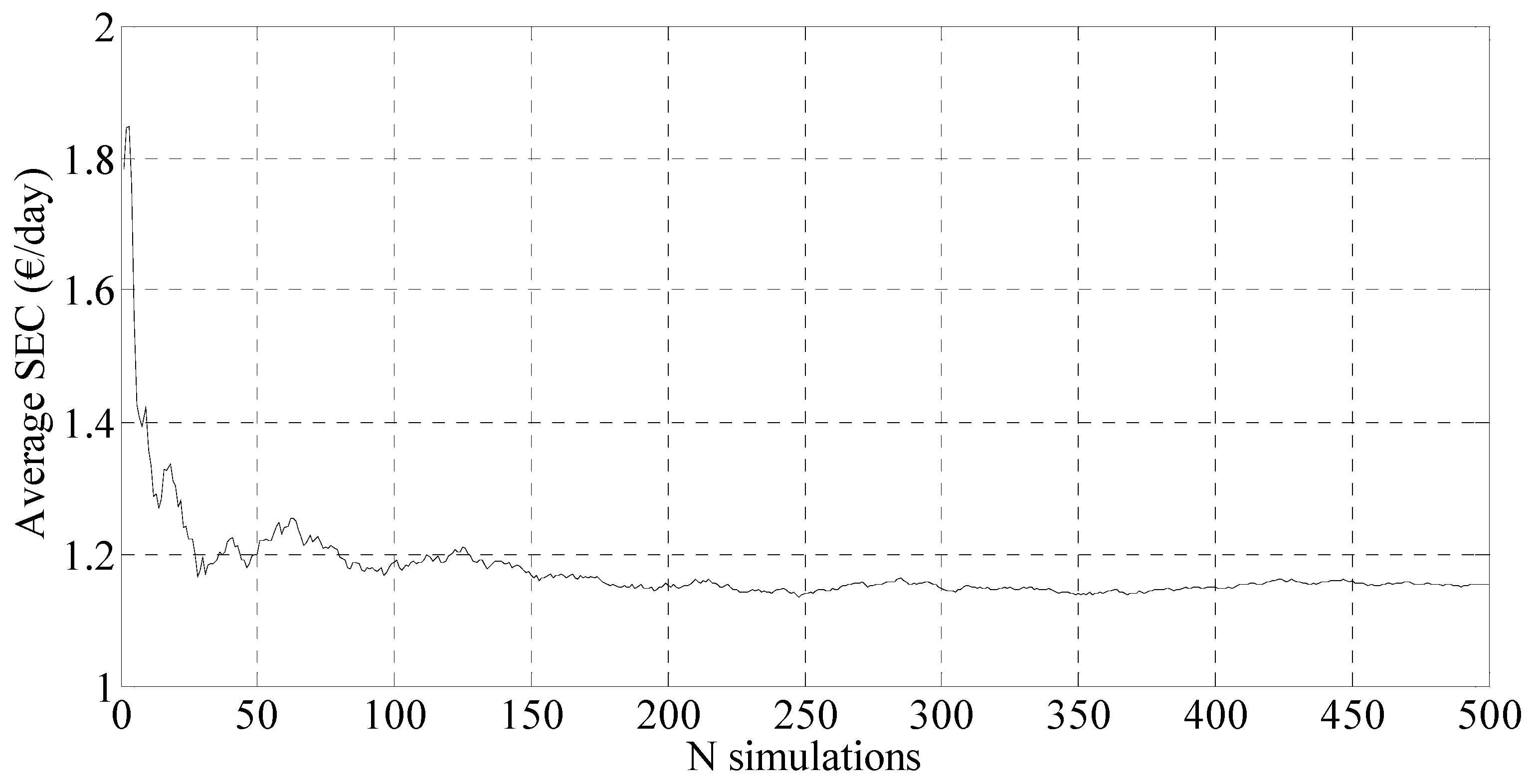
As it is known, in the MCS method, which is used to study the trend of results obtained from multiple independent simulations, a control variable should be identified to determine when the solution converges to an acceptable value. The number of iterations “N” depends on the accepted tolerance “ε” that is selected based on the trade-off between accuracy and computing time. In particular, a specified tolerance “ε” is imposed as follows:
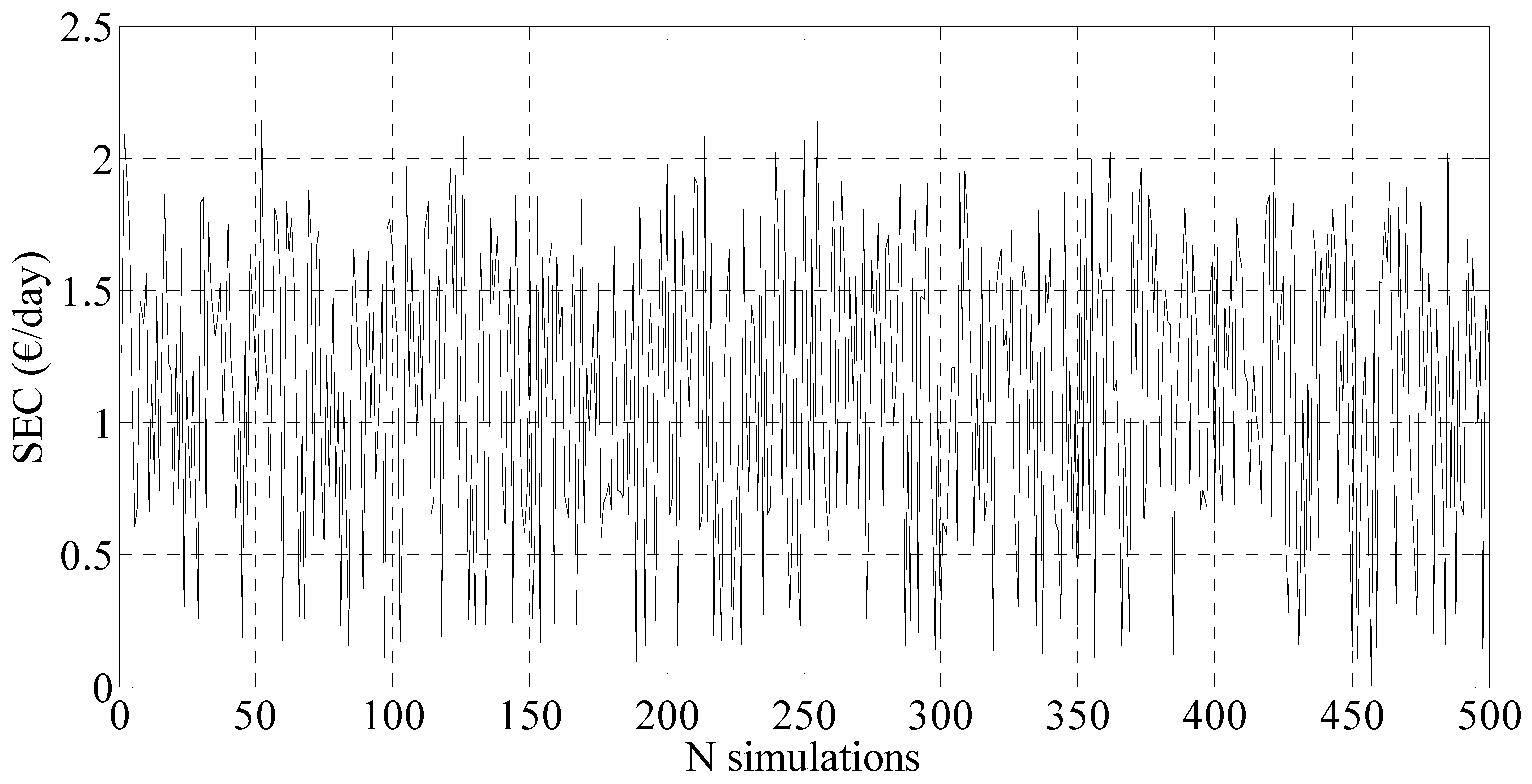
where E(X) is the mean value of the control variable of MCS sampling, σ(X) its standard deviation. A comparison between the cost with and without the hybrid PV-battery system and EMS is obtained by using the MCS [20,26]. Simulation results are shown in next figures to evidence the difference in terms of Saved Energy Cost (SEC) [4,8,26,32], considering a winter day (Figure 19).
The number of simulations (N) guarantees the convergence of the results, as shown by the moving average in Figure 20.
The proposed method is applied to obtain the Hybrid PV-Energy Storage System optimal configuration. This economic evaluation considers only the cost components dependent on the energy absorbed from the grid (EGrid). The initial cash outflow of the investment (I0) (Table 1) for each configuration system is considered, such as the cost of the PV Generator (CPVG) and the cost of the energy storage system (CESS).
The total annual cost saving is achieved considering the reduction of costs related to:
- Electricity Power System Services Cost (CPSS);
- Taxes (Tax); and
- Net Metering Service (PSSP).
For each system configuration, and for every “n” of the N simulations, the annual Total Savings Cost (TSC) [4,8] is calculated as follows:
The evaluation of the optimal configuration is based on the Discounted Payback Period (DPP) method. The DPP is the time in which the initial cash outflow of an investment (I0) is expected to be recovered from the cash inflows generated by the investment [1,32]. The advantage of this approach is that it considers the present value of money through discounting the cash inflows.
The value of the DPP, for each configuration of the hybrid system installed, is calculated as follows:
where k is the interest rate (%), Io is the hybrid system installation cost (at the year zero); CF(y) is the cash flow at the year y defined as:
TSC in Equation (10) is assumed to be equal to the mean value of the TSC for N simulations and for each configuration system.
Simulation results, shown in Table 2 and Table 3, evidence that, for both sizes of the PV system, the DPP grows with the increase the capability of the ESS. Lower DPPs can be observed for a PV-Generator size equal to 2 kW.
The most advantageous configuration of the hybrid system is therefore shown in Table 4.
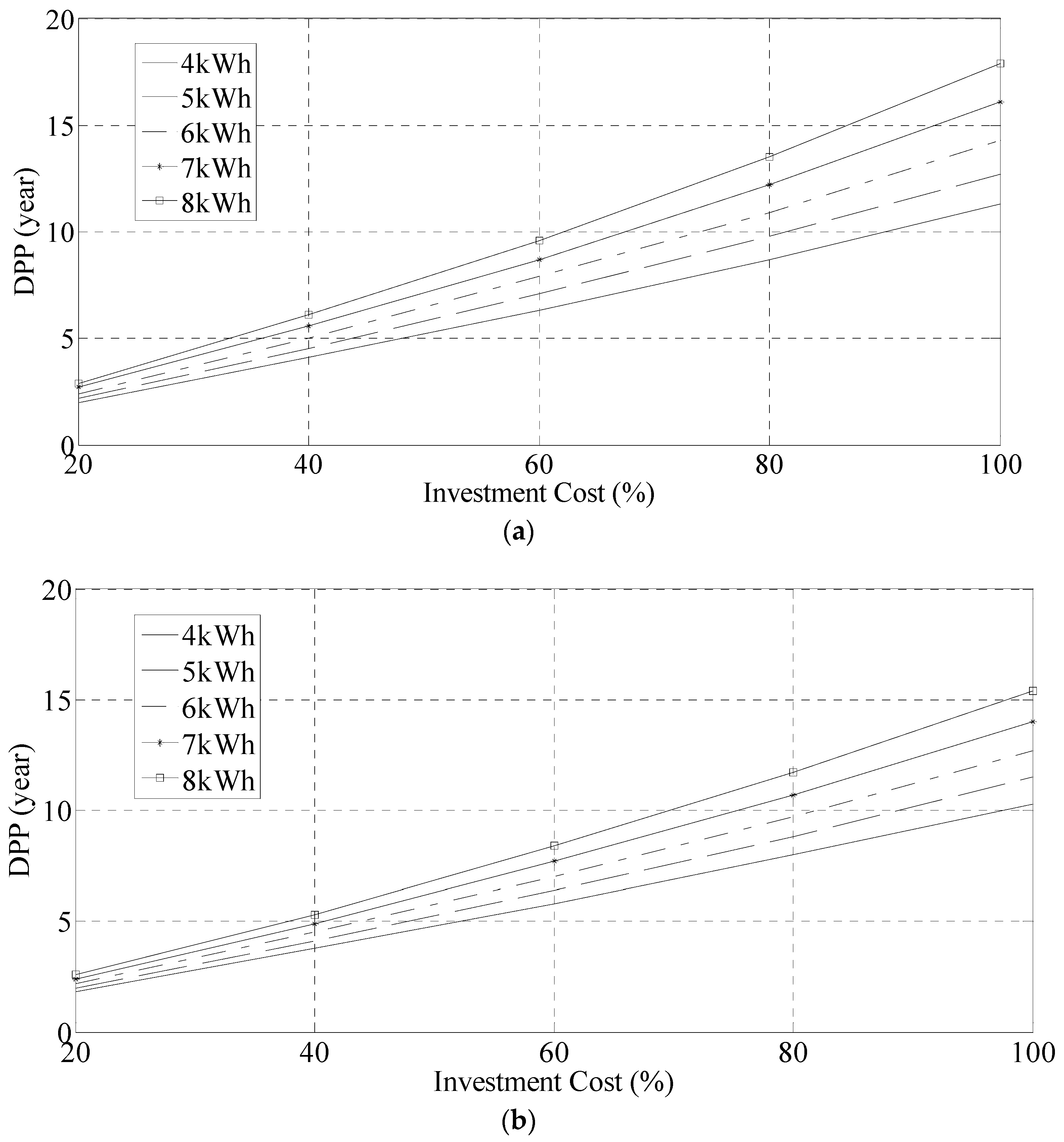
In view of market developments in the electronic components for renewable energy and energy storage systems, future scenarios, where the initial investment cost decreases to 20%, 40%, 60%, or 80% of the current cost, are considered [32]. Figure 21 shows the DPP for these feature scenarios for each configurations of the hybrid system.
It is useful to compare these results with those related to other energy management models. Specifically, in [26], the proposed system provides for control of shiftable loads and people presence-windows states, without considering the PV-battery hybrid system. The EMS proposed in this paper, combining the control strategies for shiftable loads and storage system with renewable energy, achieves a better management in terms of energy savings and end-user comfort.
5. Conclusions
In this paper a novel EMS has been proposed to manage the electrical energy in smart houses endowed with an hybrid PV-Storage Energy System and air condition systems, by considering the advantages deriving by local energy self-consumption and both electrical and thermal energy storage opportunities. Simulation results evidenced the effectiveness of the proposed EMS in decreasing both the electrical energy absorbed from the electrical grid and the costs related to electrical energy. A MCS was then proposed to find the optimal configuration of the hybrid system to achieve the best discounted payback period from the point of view of a customer willing to invest in such a system.
An evolution of the proposed EMS uses a micro-computer system that controls the shiftable loads, the hybrid PV-battery system and the energy consumption through a set of sensors connected via Z-Wave technology. The implementation of this system, already in advanced testing phase, can produce an improvement both in the electrical-thermal storage management and in the user comfort.
Author Contributions
All the authors contributed in the same way to the work reported.
Conflicts of Interest
The authors declare no conflict of interest. There are no funding sponsors supporting this article.
References
- Erdinc, O.; Paterakis, N.G.; Pappi, I.N.; Bakirtzis, A.G.; Catalão, J.P.S. A new perspective for sizing of distributed generation and energy storage for smart households under demand response. Appl. Energy 2015, 143, 26–37. [Google Scholar] [CrossRef]
- Iwafune, Y.; Ikegami, T.; Fonseca, J.G.S., Jr.; Oozeki, T.; Ogimoto, K. Cooperative home energy management using batteries for a photovoltaic system considering the diversity of households. Energy Convers. Manage. 2015, 96, 322–329. [Google Scholar] [CrossRef]
- Deeba, S.R.; Sharma, R.; Saha, T.K. Coordinated control of multi-functional battery energy storage system in an unbalanced network. IEEE Power Eng. Conf. 2014, 1, 1–6. [Google Scholar]
- Wu, Z.; Tazvinga, H.; Xia, X. Demand side management of photovoltaic-battery hybrid system. Appl. Energy 2015, 148, 294–304. [Google Scholar] [CrossRef]
- Hussein, A.A.H.; Harb, S.; Kutkut, N.; Shen, J.; Batarseh, I. Design considerations for distributed micro-storage systems in residential applications. IEEE Telecommun. Energy Conf. 2010, 1, 1–6. [Google Scholar]
- Wang, B.; Sechilariu, M.; Locment, F. Intelligent DC microgrid with smart grid communications: Control strategy consideration and design. IEEE Trans. Smart Grid 2012, 3, 2148–2156. [Google Scholar] [CrossRef]
- Tan, K.T.; So, P.L.; Chu, Y.C.; Kwan, K.H. Modeling, control and simulation of a photovoltaic power system for grid-connected and stand-alone applications. IEEE IPEC 2010, 1, 608–613. [Google Scholar]
- Zhu, D.; Wang, Y.; Chang, N.; Pedram, M. Optimal design and management of a smart residential PV and energy storage system. IEEE Des. 2014, 1, 1–6. [Google Scholar]
- Riffonneau, Y.; Bacha, S.; Barruel, F.; Ploix, S. Optimal power flow management for grid connected PV systems with batteries. IEEE Trans. Sustain. Energy 2011, 2, 309–320. [Google Scholar] [CrossRef]
- Arangarajan, V.; Oo, A.M.T.; Shafiullah, G.M.; Seyedmahmoudian, M.; Stojcevski, A. Optimum design and analysis study of stand-alone residential solar PV microgrid. IEEE Power Eng. Conf. 2014, 1, 1–7. [Google Scholar]
- Cho, J.H.; Hong, W.P. Power control and modeling of a solar-ultra capacitor hybrid energy system for stand-alone applications. IEEE Control Autom. Syst. 2010, 1, 811–814. [Google Scholar]
- Shah, A.S.M.; Ishikawa, Y.; Odakura, S.; Kakimoto, N. Power control modelling for future energy management based on photovoltaic integrated system with lithium-ion storage batteries. IEEE Model. Symp. 2014, 1, 187–192. [Google Scholar]
- Chokchai, C. Power flow control and MPPT parameter selection for residential grid-connected PV systems with battery storage. IEEE Power Electron. Conf. 2014, 1, 3789–3795. [Google Scholar]
- Kim, H.; Parkhideh, B.; Bongers, T.D.; Gao, H. Reconfigurable solar converter: A single-stage power conversion PV-battery system. IEEE Trans. Power Electron. 2013, 28, 3788–3797. [Google Scholar] [CrossRef]
- Ranaweera, I.; Sanchez, S.; Midtgard, O.M. Residential photovoltaic and battery energy system with grid support functionalities. IEEE Power Electron. Distrib. Gener. Syst. 2015, 1, 1–7. [Google Scholar]
- Choi, S.C.; Sin, M.H.; Kim, D.R.; Won, C.Y.; Jung, Y.C. Versatile power transfer strategies of PV-battery hybrid system for residential use with energy management system. IEEE Power Electron. Conf. 2014, 1, 409–414. [Google Scholar]
- Clark, J.D.; Stark, B.H. Component sizing for multi-source renewable energy systems. IEEE Ind. Inf. 2009, 1, 89–94. [Google Scholar]
- Qi, Z. Coordinated control for independent wind-solar hybrid power system. IEEE Power Energy Eng. Conf. 2012, 1, 1–4. [Google Scholar]
- Al-Falahi, M.D.A.; Wanik, M.Z.C. Modeling and performance analysis of hybrid power system for residential application. IEEE Power Eng. Conf. 2015, 1, 1–6. [Google Scholar]
- Siano, P.; Sarno, D. Assessing the benefits of residential demand response in a real time distribution energy market. Appl. Energy 2016, 161, 533–551. [Google Scholar] [CrossRef]
- Siano, P. Demand response and smart grids-a survey. Renew. Sustain. Energy Rev. 2014, 30, 461–478. [Google Scholar] [CrossRef]
- Shariatzadeha, F.; Mandalb, P.; Srivastavac, A.K. Demand response for sustainable energy systems: A review, application and implementation strategy. Renew. Sustain. Energy Rev. 2015, 45, 343–350. [Google Scholar] [CrossRef]
- Ruan, B.; Yang, Q.; Fang, X.; Yan, W. Demand response under real-time pricing for domestic energy system with DGs. IEEE Power Syst. Technol. 2014, 1, 3103–3110. [Google Scholar]
- Siano, P.; Graditi, G.; Atrigna, M.; Piccolo, A. Designing and testing decision support and energy management systems for smart homes. J. Ambient Intell. Humaniz. Comput. 2013, 4, 651–661. [Google Scholar] [CrossRef]
- Lamina, P.; Romano, R.; Sarno, D.; Siano, P.; Zakariazadeh, A. A model for wind turbines placement within a distribution network acquisition market. IEEE Trans. Ind. Inf. 2015, 11, 210–219. [Google Scholar] [CrossRef]
- Acone, M.; Romano, R.; Piccolo, A.; Siano, P.; Loia, F.; Ippolito, M.G.; Zizzo, G. Designing an energy management system for smart houses. Environ. Electr. Eng. 2015, 1, 1677–1682. [Google Scholar]
- Molderink, A.; Bakker, V.; Bosman, M.G.C.; Hurink, J.L.; Smit, G.J.M. Management and control of domestic smart grid technology. IEEE Trans. Smart Grid 2010, 1, 109–119. [Google Scholar] [CrossRef]
- Korkas, C.D.; Baldi, S.; Michailidis, I.; Kosmatopoulos, E.B. Occupancy-based demand response and thermal comfort optimization in microgrids with renewable energy sources and energy storage. Appl. Energy 2016, 163, 93–104. [Google Scholar] [CrossRef]
- Wang, X.; Palazoglu, A.; El-Farra, N.H. Operational optimization and demand response of hybrid renewable energy systems. Appl. Energy 2015, 143, 324–335. [Google Scholar] [CrossRef]
- Paterakis, N.G.; Erdinç, O.; Bakirtzis, A.G.; Catalão, J.P.S. Optimal household appliances scheduling under day-ahead pricing and load-shaping demand response strategies. IEEE Trans. Ind. Inf. 2015, 11, 1509–1519. [Google Scholar] [CrossRef]
- Shirazi, E.; Zakariazadeh, A.; Jadid, S. Optimal joint scheduling of electrical and thermal appliances in a smart home environment. Energy Convers. Manage. 2015, 106, 181–193. [Google Scholar] [CrossRef]
- Graditi, G.; Ippolito, M.G.; Telaretti, E.; Zizzo, G. Technical and economical assessment of distributed electrochemical storages for load shifting applications: An Italian case study. Renew. Sustain. Energy Rev. 2016, 57, 515–523. [Google Scholar] [CrossRef]
Figure 1.
EMS (Energy Management System) control logic.

Figure 2.
Energy flow model.

Figure 3.
EMS model flowchart.

Figure 4.
Energy Price based on “Prezzo Unico Nazionale” (PUN) during the year 2015.

Figure 5.
Cost components of the Italian electricity bill.

Figure 6.
Hardware cost in economic model: (a) PV-Generator; and (b) energy storage system.

Figure 7.
Air-conditioning energy consumption in a generic winter day.

Figure 8.
Load appliances energy consumption.

Figure 9.
Energy real time tariff for domestic use (Italian electricity market, 2015).

Figure 10.
Daily energy cost, CEGrid.

Figure 11.
Indoor and outdoor temperatures.

Figure 12.
Shiftable Loads Power: (a) without EMS; and (b) with EMS.


Figure 13.
Storage system power.

Figure 14.
State Of Charge of the battery (SOC).

Figure 15.
Use of the photovoltaic generated power.

Figure 16.
Indoor, outdoor and set point temperatures.

Figure 17.
Electrical energy absorbed by the air conditioning system.

Figure 18.
Power grid with EMS.

Figure 19.
Saved energy cost with the EMS and hybrid PV-ESS system.

Figure 20.
Moving average of the safe energy cost with EMS.

Figure 21.
DPP versus Investment (% of I0) in future scenarios for different configurations: (a) 1 kW/4–8 kWh; and (b) 2 kW/4–8 kWh.
Figure 21.
DPP versus Investment (% of I0) in future scenarios for different configurations: (a) 1 kW/4–8 kWh; and (b) 2 kW/4–8 kWh.


Table 1.
Initial investment cost (I0) (€).
| PV | ESS | ESS | ESS | ESS | ESS |
|---|---|---|---|---|---|
| 4 kWh | 5 kWh | 6 kWh | 7 kWh | 8 kWh | |
| 1 kW | 5556 | 6256 | 6956 | 7656 | 8356 |
| 2 kW | 6556 | 7256 | 7956 | 8656 | 9356 |
Table 2.
Analysis of the Discontinued Payback Period (DPP) for the configurations 1 kW/4–8 kWh.
| PV (kW) | ESS (kWh) | Io (€) | k (%) | TSC (€/y) | DPP (year) |
|---|---|---|---|---|---|
| 1 | 4 | 5556 | 3 | 586.04 | 11.3 |
| 1 | 5 | 6256 | 3 | 598.06 | 12.7 |
| 1 | 6 | 6956 | 3 | 603.81 | 14.3 |
| 1 | 7 | 7656 | 3 | 606.66 | 16.1 |
| 1 | 8 | 8356 | 3 | 608.97 | 17.9 |
Table 3.
Analysis of the Discontinued Payback Period (DPP) for the configurations 2 kW/4–8 kWh.
| PV (kW) | ESS (kWh) | Io (€) | k (%) | TSC (€/y) | DPP (year) |
|---|---|---|---|---|---|
| 2 | 4 | 6556 | 3 | 747.10 | 10.3 |
| 2 | 5 | 7256 | 3 | 757.04 | 11.5 |
| 2 | 6 | 7956 | 3 | 762.66 | 12.7 |
| 2 | 7 | 8656 | 3 | 766.15 | 14.0 |
| 2 | 8 | 9356 | 3 | 767.88 | 15.4 |
Table 4.
Optimal configuration hybrid PV-storage system for case study
| PV (kW) | ESS (kWh) | Io (€) | k (%) | TSC (€/y) | DPP (year) |
|---|---|---|---|---|---|
| 2 | 4 | 6556 | 3 | 747.10 | 10.3 |
© 2017 by the authors. Licensee MDPI, Basel, Switzerland. This article is an open access article distributed under the terms and conditions of the Creative Commons Attribution (CC BY) license (http://creativecommons.org/licenses/by/4.0/).
Share and Cite
MDPI and ACS Style
Romano, R.; Siano, P.; Acone, M.; Loia, V. Combined Operation of Electrical Loads, Air Conditioning and Photovoltaic-Battery Systems in Smart Houses. Appl. Sci. 2017, 7, 525. https://0-doi-org.brum.beds.ac.uk/10.3390/app7050525
AMA Style
Romano R, Siano P, Acone M, Loia V. Combined Operation of Electrical Loads, Air Conditioning and Photovoltaic-Battery Systems in Smart Houses. Applied Sciences. 2017; 7(5):525. https://0-doi-org.brum.beds.ac.uk/10.3390/app7050525
Chicago/Turabian StyleRomano, Roberto, Pierluigi Siano, Mariano Acone, and Vincenzo Loia. 2017. "Combined Operation of Electrical Loads, Air Conditioning and Photovoltaic-Battery Systems in Smart Houses" Applied Sciences 7, no. 5: 525. https://0-doi-org.brum.beds.ac.uk/10.3390/app7050525
Note that from the first issue of 2016, this journal uses article numbers instead of page numbers. See further details here.