Generalized Singularity Analysis of Snake-Like Robot


1
Department of Advanced Machinery Engineering, School of Engineering, Tokyo Denki University, Tokyo 120-8551, Japan
2
Department of Robotics and Mechatronics, School of Science and Technology for Future Life, Tokyo Denki University, Tokyo 120-8551, Japan
*
Author to whom correspondence should be addressed.
Appl. Sci. 2018, 8(10), 1873; https://0-doi-org.brum.beds.ac.uk/10.3390/app8101873
Submission received: 13 September 2018
/
Revised: 1 October 2018
/
Accepted: 2 October 2018
/
Published: 10 October 2018
(This article belongs to the Special Issue Advanced Mobile Robotics)
Abstract
:The purpose of this paper is to elucidate a generalized singularity analysis of a snake-like robot. The generalized analysis is denoted as analysis of singularity of a model which defines all designable parameters such as the link length and/or the position of the passive wheel as arbitrary variables. The denotation is a key point for a novelty of this study. This paper addresses the above new model denotation, while previous studies have defined the designable parameters as unique one. This difference makes the singularity analysis difficult substantively. To overcome this issue, an analysis method using redundancy of the snake-like robot is proposed. The proposed method contributes to simplify singularity analysis concerned with the designable parameters. The singular configurations of both the model including side-slipping and the one with non side-slipping are analyzed. As the results of the analysis, we show two contributions. The first contribution is that a singular configuration depends on designable parameters such as link length as well as state values such as relative angles. The second contribution is that the singular configuration is characterized by the axials of the passive wheels of all non side-slipping link. This paper proves that the singular configuration is identified as following two conditions even if the designable parameters are chosen as different variables and the model includes side-slipping link. One is that the axials of passive wheels of all non side-slipping links intersect at a common point. Another one is that axials of passive wheels of all non side-slipping links are parallel.
1. Introduction
A real snake has simple figure like a string, and can locomote by using difference between friction in the propulsive direction and one in the normal direction. It can locomote not only flatland but also irregular terrain such as desert, wildland and grassland, by choosing its motion and posture depending on environments/tasks. Moreover, it can realize skilled locomotions such as swimming, climbing, and squeezing. That is, the real snake possesses highly adaptability corresponding to the environments/tasks. A snake-like robot mimics such highly adaptability of the real snake, and is expected to be an adaptable robot corresponding to the environments/tasks.
Many literatures have reported with respect to locomotion controls of snake-like robots. Hirose, who is a pioneer of the studies for snake-like robots, has found that a curvature of a snake changes sinusoidally along its body axis. He has named it “Serpenoid Curve”, and applied it to a trajectory generation for snake-like robots [1]. Endo et al. have implemented a propulsive locomotion control of snake-like robots by using the Serpenoid Curve [2]. As studies extending the Serpenoid Curve, Yamada et al. have proposed the kinematics to stabilize head direction during tracking the robot to the Serpenoid Curve, and have implemented the kinematics on the robot [3]. Ma et al. have implemented slope climbing control by adjusted amplitude of the Serpenoid Curve via a simulator [4]. In our previous study, we have designed a servo control system for tracking to the Serpenoid Curve [5]. Relative researches with respect to propulsive control use difference of the friction forces between the propulsive direction and the normal direction also have been reported [6,7]. In our previous study, a head position control [8,9,10], a force control [11] and a slope climbing control [12] have been designed.
These researches [6,7,8,9,10,11,12] have been based on a dynamical model of the snake-like robot. The discussions on it has been reported in order to avoid singular configurations as well. In these researches, the model is generally assumed to install non side-slipping passive wheels on its links. Prautsch et al. have derived the dynamical model of the snake-like robot without side-slipping, and have proven some theories and lemmas regarding the dynamics [13,14]. As one of the results of the analyses, they have referred the snake-like robot takes the singular configuration as long as it poses either straight line or arc shape. The result has been shared by a lot of researchers. For example, Date et al. have also reported that the snake-like robot becomes singular when the robot poses straight line or arc shape [15,16,17]. In addition, Ye et al. have also stated that straight line or arc shape are singular [18]. Matsuno et al. [19] and Tanaka et al. [20,21,22] also have mentioned that the postures of straight line or arc shape are the singular configuration as well. They [15,16,17,18,19,20,21,22] have led the same results based on the analysis by Prautsch et al. [13,14]. In addition, Dear et al. [23,24] and Guo et al. [25] have reported the snake-like robot is the singular configuration when all relative angles are equivalent. It indicates the posture under this situation is either straight line or arc shape. Liljebäck et al. have addressed a dynamical model supposing the snake-like robot with side-slipping, and have derived the model with viscous friction forces working at the center of each link. They have analyzed nonlinear controllability of the models, and finally have also proven that straight line and arc shape are singular configurations [26,27,28,29].
While these studies [13,14,15,16,17,18,19,20,21,22,23,24,25,26,27,28] have addressed the either fully non side-slipping or fully side-slipping model, Tanaka et al. have addressed a model including both side-slipping and non side-slipping links [30]. They have referred that either the straight line or the arc shape are still the singular configuration with respect to the fully non side-slipping model based on Prautsch’s analysis [14]. Nevertheless, they have concluded that following two conditions are the singular configuration regarding to the model including side-slipping.
Condition
- Axials of passive wheels of all non side-slipping links intersect at a common point.
- Axials of passive wheels of all non side-slipping links are parallel.
These researches [13,14,15,16,17,18,19,20,21,22,23,24,25,26,27,28,29,30] have a common assumption that the robot has either the passive wheel or the center of gravity located at the center of each link. This common assumption means link length and/or position of the passive wheel are defined as common variable. Hence, the common assumption contributes the analysis simple, because each element of its Jacobian matrix can be factorized by link length or position of passive wheel as common variable. Accordingly, each element is able to be formulated by summation of the trigonometric functions with link length or position of passive wheel as the common variable. For example, Tanaka et al. have defined the length from a front joint to a passive wheel and the one from a passive wheel to hind joint as a same variable for all link. To satisfy this definition, they have supposed that the link length of lifted links is not changed by limiting lifting height infinitesimally, even though their robot allows to lift up it to enough height [30]. Thus, the analyses of previous studies subject to the limitation regarding to the common variable, although these variables could be designable. Conversely, effects of link position of the passive wheel and/or length to its behavior have never discussed yet.—i.e., the analysis without any limitation has never been discussed.
This paper elucidates a generalized singularity analysis of the snake-like robot. The generalized analysis is denoted as analysis of singularity of a model which defines all designable parameters such as the link length and/or the position of the passive wheel as arbitrary variables. From a viewpoint of system design, revealing a relationship between the designable parameters and system behavior affects behavior of the whole system including the locomotion control system as well. In the case of the inverted pendulum for example, it has been reported that changing its designable parameters such as link length results in extending stability margin of the system [31,32,33]. In another instance, the Jansen linkage mechanism, a representative example of closed link mechanism, is capable of transitioning its gaits significantly by changing length ratio of all link [34,35]. In addition, its characteristic influences robot’s morphology as well [36]. The snake-like robot is a kind of non-holonomic system, and its non-holonomic constraints come from the characteristic of the non side-slipping passive wheels. Hence, the position of the passive wheel affects the system behavior. Thus, discussion on effect of the designable parameters is expected to provide some advantages in this area as well.
This paper addresses two main issues. The first main issue is to elucidate dependent relationship between the singular configuration of the snake-like robot and the designable parameters such as link length and position of the passive wheel. As discussed above, the previous studies have identified that the singular configuration of the snake-like robot is either straight line or arc shape. This identification is equivalent to that the singular configuration depends on only its state vector. Tanaka et al. have referred that the postures of straight line or arc shape are the singular configuration regarding to the model with non side-slipping while they have referred that the Conditions are the singular configuration regarding to the model including side-slipping [30]. In addition, they have defined all link length as unique parameter. On the other hand, this paper addresses the model which defines the designable parameters as non-unique variables in order to reveal the relation between the singular configuration and the designable parameters. This difference of the assumptions results in a substantial increase of the analysis complexity, because the link length and the position of the passive wheel defined as different parameters are unable to factorized as common variables.
Therefore, in this paper, an analysis method using redundancy of the snake-like robot is proposed. The singular configuration of the snake-like robot is analyzed based on the method. The proposed method contributes to simplify singularity analysis concerned with the designable parameters such as link length. An epitomization of the method is to resolve the snake-like robot into subsystems every three links. Applying the same analysis to all subsystem leads to singularity analysis of whole system. Since the subsystem is absolutely smaller than the whole system, the epitomization reduces complexity coming from different parameters. The subsystem is also able to be composed corresponding to the model including side-slipping as well as the one with non side-slipping. Consequently, the singular configurations of both the model including side-slipping and the one with non side-slipping are analyzed in this paper.
The second main issue is to characterize the singular configuration of the snake-like robot by the axials of the passive wheels of all non side-slipping link. Tanaka et al. [30] have proven that the singular configuration is characterized by the axials of the passive wheels as the Conditions. The Conditions is novel characteristic to identify the singular configuration. However, they had a limitation for maintaining the uniform link length. By clearing the limitation, this paper proves effectiveness of the novel characteristic even if the designable parameters are defined as different values and the model includes side-slipping links.
This paper is organized as follows: Section 3 derives both kinematics and Jacobian matrices of the snake-like robot. Four kinds of kinematics around a joint are derived corresponding to side-slipping patterns. The Jacobian matrices of both the snake-like robot including side-slipping and the one with non side-slipping are formulated by composing the four kinds of kinematics redundantly. By applying the analysis method using redundancy, Section 4 analyzes the singular configuration of the snake-like robot. Two theories and one lemma are proven with respect to the model with non side-slipping. Also, two theories and two lemmas are proven with respect to the model including side-slipping. Section 5 visualizes the analysis results via two numerical simulations. Section 6 concludes this paper.
2. Notation
Notations used in this paper are defined here for simplicity of description. The first is regarding to representation of side-slipping on schematic figures of the snake-like robot. The second is regarding to product of matrices. The last one is regarding to a relative angle.
Notation 1.
Notation 2.
In this paper, production of matrices is represented as follows:
where, , .
Notation 3.
The relative angle of adjacent ith link and th link is represented as follow:
Whereas, the relative angle of non adjacent ith link and jth link is represented as follow:
3. Kinematics of the Snake-Like Robot
A kinematics of n-link snake-like robot including some side-slipping links is formulated in this section by deriving velocity relations around each joint. Since the snake-like robot is a kind of redundant robots, its kinematics is also able to be represented by redundant relation. Thus, to derive the kinematics of n-link snake-like robot is equivalent to derive it between adjacent links. In particular, a kinematics around a joint between adjacent non side-slipping links is derived, also, ones including side-slipping link is derived from the derived kinematics. Finally, Jacobian matrices of both the n-link snake-like robot including side-slipping and the one with non side-slipping are formulated, respectively.
3.1. Kinematics around a Joint Adjacent Two Links with Non Side-Slipping
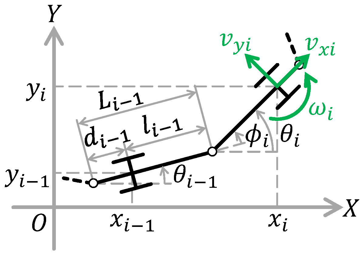
A schematic figure of a joint between adjacent non side-slipping links is shown in Figure 2. Physical parameters and state variables are denoted in Table 1 and Table 2, respectively.
From Figure 2, the passive wheel, which represents that the link is non side-slipping, is installed on arbitrary position of each link. represents absolute angle of each link, represents relative angle between ith link and th link, and represent position of the passive wheel of each link on generalized coordinate. Also, and represent length from extremity to center of gravity (COG) and length from COG to end, respectively.
The generalized coordinate and the quasi-velocity coordinate are defined. From Figure 2, the generalized coordinate of the system is defined as:
Also, the quasi-velocity of the system is defined as:
From Figure 2, the velocity transform matrix transforms the generalized coordinate to the quasi-velocity coordinate as below:
Its derivations are:
By transforming (2) to the quasi-velocity coordinate using the velocity transform matrix , and we obtain:
Please note that the relative angle of each link is defined as (Notation 3). Then,
where,
Since adjacent link is supposed non side-slipping, . Hence,
Therefore, the kinematics around a joint of two adjacent links both non side-slipping is obtained as:
where, , and represents the identity matrix .
3.2. Kinematics around a Joint Adjacent Two Links with Side-Slipping
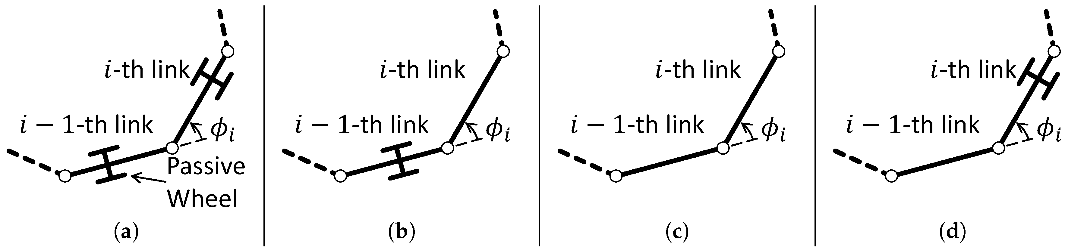
From (3) and its derivation process, the kinematics around a joint including side-slipping links are derived as well. In this paper, the passive wheel represents that the link is side-slipping or non side-slipping in order to distinguish clearly (Notation 1). Combinations of side-slipping of two adjacent link regarding around a joint are shown in Figure 3.
The kinematics of Figure 3 are formulated as follows:
Submatrices are defined as follows:
3.3. Jacobian Matrices
The Jacobian matrices of both the n-link snake-like robot including side-slipping and the one with non side-slipping are formulated by using (4)–(7) redundantly. First, the Jacobian matrix of the n-link snake-like robot with non side-slipping is formulated. A tangent speed is defined as:
The relative angular velocity vector is defined as:
Thus, the Jacobian matrix of n-link snake-like robot with non side-slipping is formulated as follow:
where, .
Next, the Jacobian matrix of the n-link snake-like robot including side-slipping is formulated. While combinations of side-slipping exist infinite on the n-link snake-like robot, the Jacobian matrix consists of (4)–(7) due to its redundancy, since product of the kinematics formulates it. We denotes a set of non side-slipping links as:
is decomposed into , where and are a relative angle vector of non side-slipping links and an one of side-slipping links respectively, and denoted as follows:
where , since is unable to be defined as angle. Subscripts with respect to the set of non side-slipping links are denoted as follow:
The Jacobian matrix of the n-link snake-like robot including side-slipping is formulated as follows:
where ∗ represents an element of the matrix.
This section has derived the kinematics around a joint corresponding to 4 patterns of side-slipping. By using the derived kinematics redundantly, the Jacobian matrices of both the n-link snake-like robot including side-slipping and the one with non side-slipping have been formulated as (9) and (8) respectively.
4. Singularity Analysis
This section analyzes singularity of n-link snake-like robot. Since elements of matrix to be analyzed is unable to factorize to summation of trigonometric function, it is inappropriate to analyze the singularity by the method of Tanaka et al. [30] in the case of the snake-like robot supposed to non-uniform designable parameters addressed in this paper. The key point of our proposed method is in redundancy of the system which is one of big reason to make the snake-like robot popular. Using redundancy results in avoidance of complexity as well as systematic solution. Our proposed method provides the analysis results as same as Tanaka’s analysis [30]. In addition, the singular configuration of the snake-like robot is identified as follows:
- Axials of passive wheel of all non side-slipping links intersect at a common point.
- Axials of passive wheel of all non side-slipping links are parallel.
The singular configuration of the snake-like robot with non side-slipping is analyzed first in order to propose our analysis method using redundancy as well as to prove that the analysis results in the above two conditions. The analysis proves as well that the singular configuration of the snake-like robot depends on the designable parameters. The singular configuration of the snake-like robot including side-slipping is analyzed next. The analysis also proves that the singular configuration of the snake-like robot is identified as the above two even if the side-slipping links are included.
4.1. Snake-Like Robot with non Side-Slipping
The singular configuration of the snake-like robot with non side-slipping is analyzed first. The previous studies have reported that the singular configuration is either straight line or arc shape—i.e., it depends on only state vector. This analysis proves that the singular configuration of the snake-like robot depends on the designable parameters (such as link length and/or the position of the passive wheel) as well as the state vector. With respect to the snake-like robot with non side-slipping, following 2 theories and 1 lemma are obtained.
Theorem 1.
Except for , (8) is rank deficient if and only if, ,
Proof.
From (8), since , rank of (8) drops when rank, and the snake-like robot poses the singular configuration. Row vectors of (8) are denoted as . Since (8) possesses one independent row vector when rank = 1, it can be written by using arbitrary constants as follows:
where, . Rank of (12) equals 1 even if any 2 row vectors are chosen.—i.e., if submatrices , consisting of adjacent two row vectors, satisfy ∀rank = 1, rank = 1 and is rank deficient. is
From
since is rank safficient,
By finding rank deficient conditions of , that is, solving , the conditions of which the snake-like robot poses the singular configuration are identified.
Please note that if , it might be able to rank rank = 2 even if ∀rank = 1 in (12). In particular, when
rank = 2, if and are linear independent. However, it is determined as rank deficient in above mentioned condition, because rank = rank = 1. Since , only when . Because
as long as . Furthermore, as long as even if .
Equation (11) clearly shows that the singular configuration of the snake-like robot depends on the designable parameters as well as the state vector. Thus, it is limited into neither straight line nor arc shape. Equation (11) indicates to be unable to factorize to summation of trigonometric function due to different coefficients in the premise of different parameter definition. Furthermore, complexity of is more apparent than (11). This predisposition points difficulty of analyzing the Jacobian matrix at a time, and the method using redundancy has an advantage for avoiding the complexity.
Lemma 1.
, —i.e., if and only if the axials of the passive wheel overlap.
Proof.
In (13),
and equation in parentheses equals x coordinate of jth link corresponding to th link. Hence, the wheels of jth link and th link overlap when . Thus, the axials of the passive wheel clearly overlap if . □
The proposed analysis method is capable of analyzing simply even though the designable parameters of each link are defined as different ones. On the other hand, it has been shown the analysis method outputs uncertain result if the special condition () is satisfied. It also has been proven that the condition is satisfied when the axials of the adjacent passive wheels overlap. Since it is pose of which the links wholly overlaps, the actual snake-like robot generally never take that pose.
Theorem 2.
The snake-like robot is singular if and only if the axials of all passive wheel intersect at a common point or are parallel.
Proof.
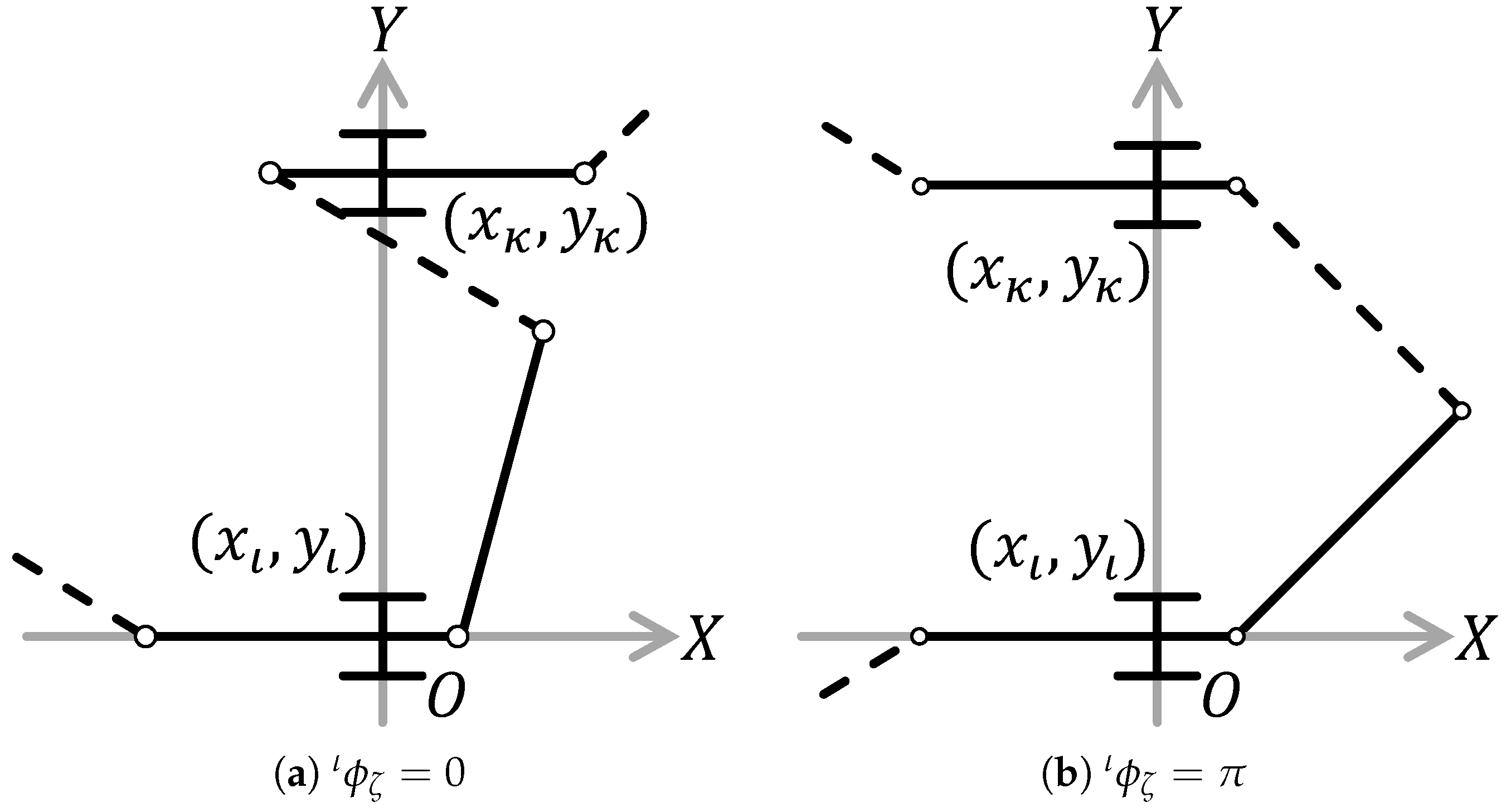
ith link is focused on. A coordinate is set the origin at position of the passive wheel of ith link, and let the X axis and the Y axis are on its propulsive direction and normal direction of the passive wheel respectively. Let and are an intercept of the axial of the passive wheel of th link and the one of th link respectively. The axials of the passive wheels of all th, ith and th link intersect at a common point, if . It is proven that equations of the intercepts on that situation equals to (11). Figure 4 depicts the axials of all th, ith and th link.
The position of the passive wheel of th link is
Since a slope of the th link equals , a slope of the axial of the passive wheel is follow:
Hence, the intercept of the passive wheel of the th link is
Also, the intercept of the passive wheel of the th link is
If ,
By multiplying to the both side,
4.2. Snake-Like Robot with Side-Slipping
The singular configuration of the snake-like robot including side-slipping is analyzed next. It also analyzed as same as the one with non side-slipping as well. An analysis result shows that it satisfies the two conditions mentioned at beginning of this section. With respect to the snake-like robot including side-slipping, following 2 theories and 2 lemmas are obtained.
Theorem 3.
Except for , (9) is rank deficient if and only if ,
Proof.
From (9), since columns after 3rd column are clearly rank sufficient and , rank of (9) drops and the snake-like robot is singular, when rank. (10) is analyzed as well as (8). Thus, conditions of which rank drops are formulated. Where,
is expanded with supposing as the most complex case.
Thus,
is transformed as:
Equation (15) also indicates as well as (11) that the singular configuration of the snake-like robot depends on the designable parameters as well as the state vector.
Lemma 2.
is singular if and only if the joint of next non side-lipping link is placed on a axial of the passive wheel of current non side-slipping link (see Figure 5).
Proof.
In (16),
and an equation in the parentheses equals the x coordinate of the joint of th link corresponding to th link. □
Lemma 3.
if and only if the axials of both current and next non side-slipping link overlap (see Figure 6).
Proof.
Thus,
An equation in the parentheses equals x coordinate of the passive wheel of next non side-slipping link (th link) of when . Hence, the axials of the passive wheel of both current and next non side-slipping link overlap. □
Theorem 4.
The snake-like robot is singular if and only if the axials of passive wheel of all non side-slipping links intersect at a common point or are parallel.
Proof.
th link is focused on. A coordinate is set the origin at position of the passive wheel of th link, and let the X axis and the Y axis are on its propulsive direction and normal direction of the passive wheel respectively. Let and are an intercept of the axial of the passive wheel of th link and the one of th link respectively. The axials of the passive wheels of all th, th and th link intersect at a common point, if . It is proven that equations of the intercepts on that situation equals to (15). Figure 7 depicts the axials of all th, th and th link.
The position of the passive wheel of th link is
Since a slope of the th link equals , a slope of the axial of the passive wheel is follow:
Hence, the intercept of the passive wheel of the th link is
Also, the intercept of the passive wheel of the th link is
If ,
By multiplying to the both side,
5. Numerical Simulation
It has been so far identified as following two conditions. One is that the axials of all passive wheel intersect at a point. Another is that the axials of all passive wheel are parallel. To show the singular configuration particularly, this section visualizes the singular configuration via two simulations. According to the analysis process in this paper, first simulation verifies that the singaular configuration of the snake-like robot depends on the designable parameters as well as the state vector. Second simulation verifies that the singular configuration of the snake-like robot is able to be characterized by axials of the passive wheels of all non side-slipping links. Both simulations analyze both the snake-like robot including side-slipping and the one with non side-slipping, and performed by MaTX VC version 5.3.45 [37]. The designable parameters used in the both simulations is shown in Table 3.
The first simulation visualizes the state vectors of the singular configuration in the state coordinate space. The state vectors of the singular configuration of the both 3-link and 4-link snake-like robot with non side-slipping are calculated by solving (11). In addition, the state vectors of the singular configuration of the 4-link snake-like robot including side-slipping are calculated by solving (15).
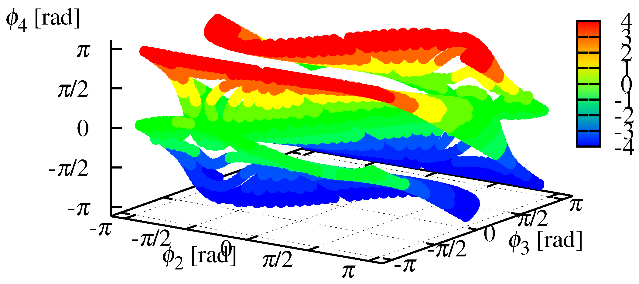
Figure 8 and Figure 9 show the relative angles on the singular configuration in the state coordinate space. Red shows singular configuration with m and m (Case 1 in Table 3). This configuration has been defined as singular configuration in the previous studies. In fact, red shows state values of either straight line or arc shape. If the singular configuration is either straight line or arc shape—i.e., it depends on the state values only, the relative angles in the state coordinate space are unchanged even if the designable parameters are changed. However, green and blue in both Figure 8 and Figure 9 are absolutely discord. That is, Figure 8 and Figure 9 clearly show that the singular configuration of the snake-like robot depends on the designable parameters as well as the state values. Figure 10 and Figure 11 show the relative angles on the singular configuration including side-slipping in the state coordinate space, and these are absolutely discord. Hence, Figure 10 and Figure 11 also clearly show that the singular configuration of the snake-like robot depends on the designable parameters as well as the state values. Thus, the designable parameters affect dynamics of the snake-like robot.
Second simulation shows the axials of the passive wheel of all non side-slipping links intersect at a common point when the snake-like robot is singular. The singular configuration of 4-link snake-like robot is analyzed. Case 2 and Case 3 in Table 3 are chosen as the designable parameters. Let rad for Case 2 and for Case 3, and the intercepts of the axials of the passive wheel and the singular configurations are obtained by solving (11) and (14). Simulation results are shown in Figure 12, Figure 13, Figure 14 and Figure 15.
Figure 12, Figure 13, Figure 14 and Figure 15 shows that the axials of the passive wheel intersect at a common point, when the snake-like robot is singular. Since rad and rad in Figure 12, rad and rad in Figure 13, rad in Figure 14 and rad in Figure 15, the singular configuration of the snake-like robot is not limited to either straight line or arc shape.
This two simulations has proven that the singular configuration of the snake-like robot depends on the designable parameters as well as the state values, and it is characterized by the intersection of the axials rather than the state values.
6. Conclusions
This paper has elucidated the generalized singularity analysis of the snake-like robot affected by the designable parameters such as the link length and/or the position of the passive wheel. This paper has addressed the model installing the passive wheel on arbitrary position, while the previous studies had addressed the model installing the wheel on the center of each link.
By applying the method using redundancy of the snake-like robot, we have reduced high complexity due to different set-up corresponding to the non-unique designable parameters such as link length and/or the position of the passive wheel. First, the kinematics around a joint of two adjacent links installing the passive wheel on arbitrary position have been derived corresponding to four patterns of side-slipping. By composing the joint kinematics redundantly, the kinematics of whole snake-like robot is formulated. Second, the Jacobian matrices of both the one including side-slipping and the one with non side-slipping have been formulated by using the kinematics. Finally, the rank deficient conditions of the Jacobian matrices—i.e., the singular configuration of the snake-like robot have been analyzed.
The analysis creates two contributions. The first contribution is that the singular configuration depends on the designable parameters such as link length and/or the position of the passive wheel as well as the state vector consisted of the relative angles. Theorem 1 and 3 have revealed the relation between the singular configuration of the snake-like robot and the designable parameters, while the previous studies have reported that the singular configuration depends on only the state vector. The second contribution is that the singular configuration of the snake-like robot is able to be characterized by the axials of the passive wheel of all non side-slipping link. Theorem 2 and 4 have proven that the singular configuration of the snake-like robot is identified as the following two conditions regardless of whether the side-slippings actually exist.
- Axials of passive wheels of all non side-slipping links intersect at a common point.
- Axials of passive wheels of all non side-slipping links are parallel.
These analyses lead shows discussions on the system design in the previous studies was insufficient. Conversely, this paper has shown importance, necessity and possibility of the discussion with respect to the system design including the locomotion control system as well as the designable parameters in the area of the snake-like robot. The discussion of the system design has a lot of possibilities to be a new index of mechanical design. For example in the area of the snake-like robot, we will be able to design a robot which is unlikely to result in the singular configuration as well as a novel locomotion control system. For another instance, the discussion will lead to invent a novel snake-like robot which can control the position of passive wheels actively. Also for another robotic system, the discussion helps robot’s mechanical design corresponding to its intended use. Especially for unstable system, the discussion contributes to maximize its stability region.
Author Contributions
S.N., M.I. and H.I. conceptualized the paper. S.N. conceived and proofed the theorems and the lemmas. S.N. performed the numerical simulations. S.N., M.I. and H.I. wrote the paper.
Funding
This research received no external funding.
Conflicts of Interest
The authors declare no conflict of interest.
References
- Hirose, S. Biologically Inspired Robots: Snake-Like Locomotors and Manipulators; Oxford University Press: Oxford, UK, 1993. [Google Scholar]
- Endo, G.; Togawa, K.; Hirose, S. Study on self-contained and terrain adaptive active cord mechanism. In Proceedings of the IEEE/RSJ International Conference on Intelligent Robots and Systems IROS’99, Kyongju, Korea, 17–21 October 1999; Volume 3, pp. 1399–1405. [Google Scholar]
- Yamada, H.; Mori, M.; Hirose, S. Stabilization of the head of an undulating snake-like robot. In Proceedings of the IEEE/RSJ International Conference on Intelligent Robots and Systems, San Diego, CA, USA, 29 October–2 November 2007; pp. 3566–3571. [Google Scholar]
- Ma, S.; Tadokoro, N. Analysis of creeping locomotion of a snake-like robot on a slope. Auton. Robots 2006, 20, 15–23. [Google Scholar] [CrossRef]
- Nansai, S.; Iwase, M. Tracking control of snake-like robot with rotational elastic actuators. In Proceedings of the 2012 12th International Conference on Control, Automation and Systems (ICCAS), JeJu Island, Korea, 17–21 October 2012; pp. 678–683. [Google Scholar]
- Yamakita, M.; Hashimoto, M.; Yamada, T. Control of locomotion and head configuration of 3D snake robot (SMA). In Proceedings of the IEEE International Conference on Robotics and Automation, ICRA’03, Taipei, Taiwan, 14–19 September 2003; Volume 2, pp. 2055–2060. [Google Scholar]
- Matsuno, F.; Sato, H. Trajectory tracking control of snake robots based on dynamic model. In Proceedings of the IEEE International Conference on Robotics and Automation, ICRA 2005, Barcelona, Spain, 18–22 April 2005; pp. 3029–3034. [Google Scholar]
- Watanabe, K.; Iwase, M.; Hatakeyama, S.; Maruyama, T. Control strategy for a snake-like robot based on constraint force and its validation. In Proceedings of the 2007 IEEE/ASME International Conference on Advanced Intelligent Mechatronics, Zurich, Switzerland, 4–7 September 2007; pp. 1–6. [Google Scholar]
- Watanabe, K.; Iwase, M.; Hatakeyama, S.; Maruyama, T. Control strategy for a snake-like robot based on constraint force and verification by experiment. Adv. Robot. 2009, 23, 907–937. [Google Scholar] [CrossRef]
- Yanagida, T.; Kasahara, M.; Iwase, M. Locomotion Control of Snake-like Robot on Geometrically Smooth Surface. IFAC-PapersOnLine 2015, 48, 162–167. [Google Scholar] [CrossRef]
- Nansai, S.; Elara, M.R.; Iwase, M. Dynamic Hybrid Position Force Control using Virtual Internal Model to realize a cutting task by a snake-like robot. In Proceedings of the 2016 6th IEEE International Conference on Biomedical Robotics and Biomechatronics (BioRob), Singapore, 26–29 June 2016; pp. 151–156. [Google Scholar]
- Tashiro, K.; Nansai, S.; Iwase, M.; Hatakeyama, S. Development of snake-like robot climbing up slope in consideration of constraint force. In Proceedings of the IECON 2012-38th Annual Conference on IEEE Industrial Electronics Society, Montreal, QC, Canada, 25–28 October 2012; pp. 5422–5427. [Google Scholar]
- Prautsch, P.; Mita, T. Control and analysis of the gait of snake robots. In Proceedings of the 1999 IEEE International Conference on Control Applications, Kohala Coast, HI, USA, 22–27 August 1999; Volume 1, pp. 502–507. [Google Scholar]
- Prautsch, P.; Mita, T.; Iwasaki, T. Analysis and control of a gait of snake robot. IEEJ Trans. Ind. Appl. 2000, 120, 372–381. [Google Scholar] [CrossRef]
- Date, H.; Hoshi, Y.; Sampei, M. Locomotion control of a snake-like robot based on dynamic manipulability. In Proceedings of the IEEE/RSJ International Conference on Intelligent Robots and Systems, Takamatsu, Japan, 31 October–5 November 2000; Volume 3, pp. 2236–2241. [Google Scholar]
- Date, H.; Hoshi, Y.; Sampei, M.; Nakaura, S. Locomotion control of a snake robot with constraint force attenuation. In Proceedings of the American Control Conference, Arlington, VA, USA, 25–27 June 2001; Volume 1, pp. 113–118. [Google Scholar]
- Date, H.; Sampei, M.; Nakaura, S. Control of a snake robot in consideration of constraint force. In Proceedings of the 2001 IEEE International Conference on Control Applications (CCA’01), Mexico City, Mexico, 7 September 2001; pp. 966–971. [Google Scholar]
- Ye, C.; Ma, S.; Li, B.; Wang, Y. Locomotion control of a novel snake-like robot. In Proceedings of the 2004 IEEE/RSJ International Conference on Intelligent Robots and Systems (IROS 2004), Sendai, Japan, 28 September–2 October 2004; Volume 1, pp. 925–930. [Google Scholar]
- Matsuno, F.; Sato, H. Trajectory tracking control of snake robots based on dynamic model. In Proceedings of the 2005 IEEE International Conference on Robotics and Automation, ICRA 2005, Barcelona, Spain, 18–22 April 2005; pp. 3029–3034. [Google Scholar]
- Tanaka, M.; Tanaka, K. Climbing and descending control of a snake robot on step environments based on kinematics. In Proceedings of the 2013 IEEE/RSJ International Conference on Intelligent Robots and Systems (IROS), Tokyo, Japan, 3–7 November 2013; pp. 3285–3290. [Google Scholar]
- Tanaka, M.; Matsuno, F. Modeling and control of head raising snake robots by using kinematic redundancy. J. Intell. Robot. Syst. 2014, 75, 53–69. [Google Scholar] [CrossRef]
- Tanaka, M.; Tanaka, K. Control of a snake robot for ascending and descending steps. IEEE Trans. Robot. 2015, 31, 511–520. [Google Scholar] [CrossRef]
- Dear, T.; Kelly, S.D.; Travers, M.; Choset, H. Locomotive analysis of a single-input three-link snake robot. In Proceedings of the 2016 IEEE 55th Conference on Decision and Control (CDC), Las Vegas, NV, USA, 12–14 December 2016; pp. 7542–7547. [Google Scholar]
- Dear, T.; Kelly, S.D.; Travers, M.; Choset, H. The three-link nonholonomic snake as a hybrid kinodynamic system. In Proceedings of the American Control Conference (ACC), Boston, MA, USA, 6–8 July 2016; pp. 7269–7274. [Google Scholar]
- Guo, X.; Ma, S.; Li, B.; Wang, M.; Wang, Y. Modeling and optimal torque control of a snake-like robot based on the fiber bundle theory. Sci. China Inf. Sci. 2015, 58, 1–13. [Google Scholar] [CrossRef]
- Liljebäck, P.; Pettersen, K.Y.; Stavdahl, Ø.; Gravdahl, J.T. Controllability analysis of planar snake robots influenced by viscous ground friction. In Proceedings of the IEEE/RSJ International Conference on Intelligent Robots and Systems, St. Louis, MO, USA, 10–15 October 2009; pp. 3615–3622. [Google Scholar]
- Liljebäck, P.; Pettersen, K.Y.; Stavdahl, Ø.; Gravdahl, J.T. Stability analysis of snake robot locomotion based on averaging theory. In Proceedings of the 2010 49th IEEE Conference on Decision and Control (CDC), Atlanta, GA, USA, 15–17 December 2010; pp. 1977–1984. [Google Scholar]
- Liljebäck, P.; Pettersen, K.Y.; Stavdahl, Ø.; Gravdahl, J.T. Controllability and stability analysis of planar snake robot locomotion. IEEE Trans. Autom. Control 2011, 56, 1365–1380. [Google Scholar]
- Pettersen, K.Y.; Liljebäck, P.; Stavdahl, Ø.; Gravdahl, J.T. Snake Robots From Biology to Nonlinear Control. IFAC Proc. Volumes 2013, 46, 110–115. [Google Scholar] [CrossRef]
- Tanaka, M.; Tanaka, K. Singularity analysis of a snake robot and an articulated mobile robot with unconstrained links. IEEE Trans. Control Syst. Technol. 2016, 24, 2070–2081. [Google Scholar] [CrossRef]
- Onishi, Y.; Izutu, M.; Iwase, M. Link lengths search using genetic algorithm for stabilization of quintuple inverted pendulum. In Proceedings of the 2011 SICE Annual Conference (SICE), Tokyo, Japan, 13–18 September 2011; pp. 739–744. [Google Scholar]
- Shiraishi, D.; Oonishi, Y.; Izutsu, M.; Hatakeyama, S. Study of system structure with controllability matrix. In Proceedings of the 54th Japan Joint Automatic Control Conference, Tokyohashi, Japan, 19–20 November 2011; Volume 54, p. 29. [Google Scholar]
- Nagaki, K.; Izutsu, M.; Hatakeyama, S.; Iwase, M. Structure evaluation applying stabilizable space for physical parameter. In Proceedings of the IECON 2016-42nd Annual Conference of the IEEE Industrial Electronics Society, Florence, Italy, 23–26 October 2016; pp. 642–647. [Google Scholar]
- Nansai, S.; Rojas, N.; Elara, M.R.; Sosa, R. Exploration of adaptive gait patterns with a reconfigurable linkage mechanism. In Proceedings of the 2013 IEEE/RSJ International Conference on Intelligent Robots and Systems (IROS), Tokyo, Japan, 3–7 November 2013; pp. 4661–4668. [Google Scholar]
- Nansai, S.; Rojas, N.; Elara, M.R.; Sosa, R.; Iwase, M. On a Jansen leg with multiple gait patterns for reconfigurable walking platforms. Adv. Mech. Eng. 2015, 7. [Google Scholar] [CrossRef] [Green Version]
- Nansai, S.; Rojas, N.; Elara, M.R.; Sosa, R.; Iwase, M. A novel approach to gait synchronization and transition for reconfigurable walking platforms. Digit. Commun. Netw. 2015, 1, 141–151. [Google Scholar] [CrossRef]
- Koga, M. MaTX/RtMaTX: A Freeware for Integrated CACSD. In Proceedings of the 1999 IEEE International Symposium on Computer Aided Control System Design, Kohala Coast, HI, USA, 27 August 1991; pp. 452–456. [Google Scholar]
Figure 1.
The distinction between a side-slipping link and a non side-slipping link. (a): a non side-slipping link. (b): a side-slipping link.
Figure 1.
The distinction between a side-slipping link and a non side-slipping link. (a): a non side-slipping link. (b): a side-slipping link.

Figure 2.
The schematic figure of the joint of two adjacent links both without side-slipping.

Figure 3.
Combinations of side-slipping of ith link and th link. (a): Both adjacent links are non side-slipping. (b): Only hind link is side-slipping. (c): Both adjacent links are side-slipping. (d): Only front link is side-slipping. A link with the passive wheel represents a non side-lipping link.
Figure 3.
Combinations of side-slipping of ith link and th link. (a): Both adjacent links are non side-slipping. (b): Only hind link is side-slipping. (c): Both adjacent links are side-slipping. (d): Only front link is side-slipping. A link with the passive wheel represents a non side-lipping link.

Figure 4.
Schematic figure of the axials of the passive wheels in th and th link, when ith link is focused on.
Figure 4.
Schematic figure of the axials of the passive wheels in th and th link, when ith link is focused on.

Figure 5.
An example of singularity of .

Figure 6.
Examples of configurations of .

Figure 7.
Schematic figure of the axials of the passive wheels in th and th link, when th link is focused on.
Figure 7.
Schematic figure of the axials of the passive wheels in th and th link, when th link is focused on.

Figure 8.
Singular configuration of the 3-link snake-like robot with non-sideslipping. Red: Singular configuration with m and m (Case 1 in Table 3). This configuration has been defined as singular configuration in the previous studies. Green: Singular configuration with m and m (Case 2 in Table 3). Blue: Singular configuration with m and m (Case 3 in Table 3).

Figure 9.
Singular configuration of the 4-link snake-like robot with non-sideslipping. Red: Singular configuration with m and m (Case 1 in Table 3). This configuration has been defined as singular configuration in the previous studies. Green: Singular configuration with m and m (Case 2 in Table 3). Blue: Singular configuration with m and m (Case 3 in Table 3).

Figure 10.
Singular configuration of the 4-link snake-like robot including side-slipping with m and m (Case 2 in Table 3). The third link is supposed as slipping link.
Figure 10.
Singular configuration of the 4-link snake-like robot including side-slipping with m and m (Case 2 in Table 3). The third link is supposed as slipping link.

Figure 11.
Singular configuration of the 4-link snake-like robot including side-slipping with m and m (Case 3 in Table 3). The third link is supposed as slipping link.
Figure 11.
Singular configuration of the 4-link snake-like robot including side-slipping with m and m (Case 3 in Table 3). The third link is supposed as slipping link.

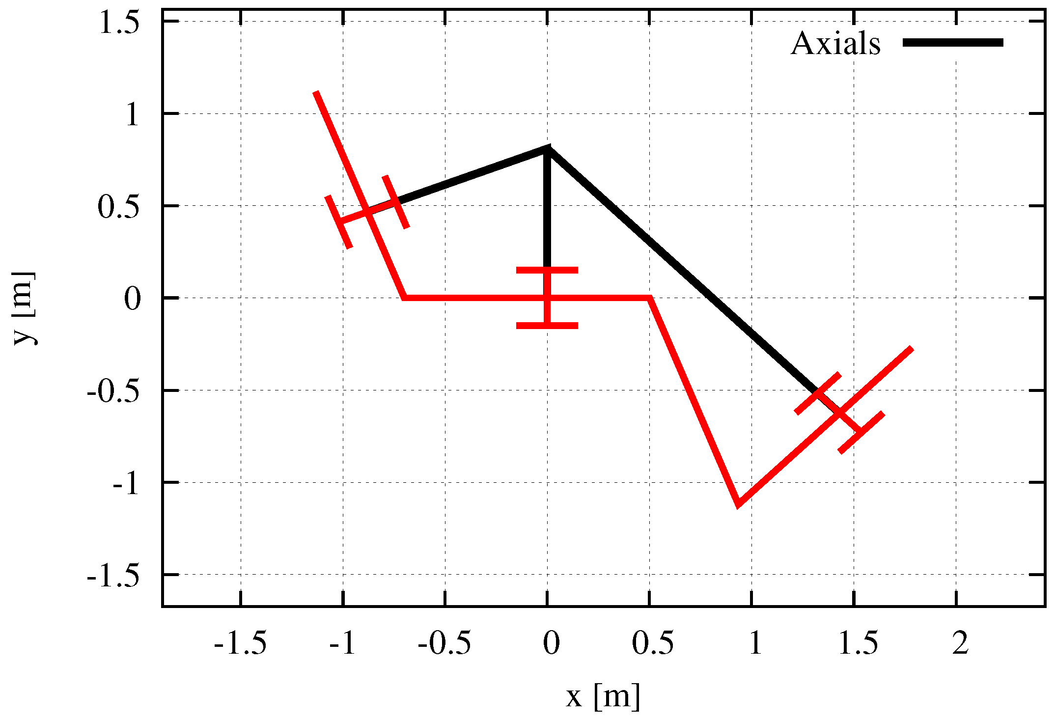
Figure 12.
Case 2: The singular configuration of 4-link snake-like robot without side-slipping when setting rad, m and m. rad and rad on this situation. Brack: The axial of the passive wheel. The posture is not arc shape, however, these intersect at a point.
Figure 12.
Case 2: The singular configuration of 4-link snake-like robot without side-slipping when setting rad, m and m. rad and rad on this situation. Brack: The axial of the passive wheel. The posture is not arc shape, however, these intersect at a point.

Figure 13.
Case 3: The singular configuration of 4-link snake-like robot without side-slipping when setting rad, m and m. rad and rad on this situation. Brack: The axial of the passive wheel. The posture is not arc shape, however, these intersect at a point.
Figure 13.
Case 3: The singular configuration of 4-link snake-like robot without side-slipping when setting rad, m and m. rad and rad on this situation. Brack: The axial of the passive wheel. The posture is not arc shape, however, these intersect at a point.

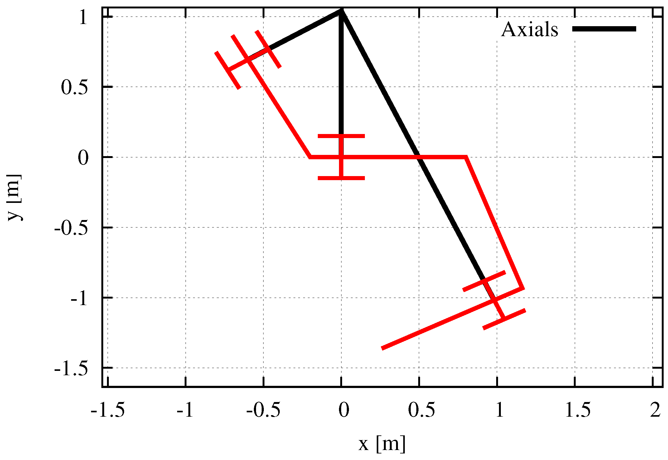
Figure 14.
Case 2: The singular configuration of 4-link snake-like robot including side-slipping when setting rad, rad as slipping link, m and m. rad on this situation. Brack: The axial of the passive wheel. The posture is not arc shape, however, these intersect at a point.
Figure 14.
Case 2: The singular configuration of 4-link snake-like robot including side-slipping when setting rad, rad as slipping link, m and m. rad on this situation. Brack: The axial of the passive wheel. The posture is not arc shape, however, these intersect at a point.

Figure 15.
Case 3: The singular configuration of 4-link snake-like robot including side-slipping when setting rad, rad as slipping link, m and m. rad on this situation. Brack: The axial of the passive wheel. The posture is not arc shape, however, these intersect at a point.
Figure 15.
Case 3: The singular configuration of 4-link snake-like robot including side-slipping when setting rad, rad as slipping link, m and m. rad on this situation. Brack: The axial of the passive wheel. The posture is not arc shape, however, these intersect at a point.


Table 1.
Physical Parameters .
| Parameters | Notation |
|---|---|
| Link length | [m] |
| Length from COG to end | [m] |
| Length from extremity to COG | [m] |
Table 2.
State Variables .
| Variables | Notation |
|---|---|
| Position in x-coordinate | [m] |
| Position in y-coordinate | [m] |
| Absolute angle of each link | [rad] |
| Relative angle between ith link and th link | [rad] |
| Velocity in the propulsive direction | [m/s] |
| Velocity in the normal direction | [m/s] |
| Angular velocity of each link | [rad/s] |
Table 3.
Parameters in Numerical Simuations ().
| Parameters | Case 1 | Case 2 | Case 3 |
|---|---|---|---|
| [m] | 1.0 | 0.7 | 0.2 |
| [m] | 1.0 | 0.5 | 0.8 |
© 2018 by the authors. Licensee MDPI, Basel, Switzerland. This article is an open access article distributed under the terms and conditions of the Creative Commons Attribution (CC BY) license (http://creativecommons.org/licenses/by/4.0/).
Share and Cite
MDPI and ACS Style
Nansai, S.; Iwase, M.; Itoh, H. Generalized Singularity Analysis of Snake-Like Robot. Appl. Sci. 2018, 8, 1873. https://0-doi-org.brum.beds.ac.uk/10.3390/app8101873
AMA Style
Nansai S, Iwase M, Itoh H. Generalized Singularity Analysis of Snake-Like Robot. Applied Sciences. 2018; 8(10):1873. https://0-doi-org.brum.beds.ac.uk/10.3390/app8101873
Chicago/Turabian StyleNansai, Shunsuke, Masami Iwase, and Hiroshi Itoh. 2018. "Generalized Singularity Analysis of Snake-Like Robot" Applied Sciences 8, no. 10: 1873. https://0-doi-org.brum.beds.ac.uk/10.3390/app8101873
Note that from the first issue of 2016, this journal uses article numbers instead of page numbers. See further details here.