Quantification of the Transmission Properties of Anisotropic Metasurfaces Illuminated by Finite-Size Beams


1
Département d’Optique, Institut FEMTO-ST, Unité Mixte de Recherche (UMR) Centre National de la Recherche Scientifique (CNRS) 6174, Université Bourgogne Franche-Comté, 25030 Besançon, France
2
Département de Physique, Ecole Normale Supérieure de Kouba B.P. 92, 16050 Algiers, Algeria
3
Department of Electrical and Computer Engineering, University of California San Diego, La Jolla, CA 92093-0407, USA
*
Author to whom correspondence should be addressed.
Appl. Sci. 2018, 8(10), 2001; https://0-doi-org.brum.beds.ac.uk/10.3390/app8102001
Submission received: 4 September 2018
/
Revised: 30 September 2018
/
Accepted: 18 October 2018
/
Published: 22 October 2018
(This article belongs to the Special Issue Sub-wavelength Optics)
Abstract
:The aim of this paper is to present an analytical method to quantitatively address the influence of a focusing illumination on the optical response properties of a metasurface illuminated by a finite-size beam. Most theoretical and numerical studies are performed by considering an infinite periodic structure illuminated by a plane wave. In practice, one deals with a finite-size illumination and structure. The combination of the angular spectrum expansion with a monomodal modal method is used to determine the beam size needed to acquire efficient properties of a metasurface that behaves as an anisotropic plate. Interesting results show that the beam-size can be as small as periods to recover the results of a plane wave. Other results also show that the beam-size can be used as an extrinsic parameter to enhance the anisotropic metasurface performance and to adjust its expected properties finely (birefringence and/or transmission coefficient). These findings are important for the design of real (finite) structures and can be adapted for experimental conditions to achieve optimized results and take full advantage of the metamaterial properties.
More often than not, theoretical studies dealing with the design of a periodic metamaterial exhibiting unique properties (extraordinary or enhanced transmission, large anisotropy, enhanced nonlinearity, chirality, etc.) involve an infinite periodic structure illuminated by a plane wave [1,2,3,4]. This approach is questionable when dealing with finite-size optical beams and/or finite-size structures. This becomes critical when the properties of the metamaterial are very sensitive to the illumination angle of incidence. This happens especially when surface plasmon resonances are involved. In the latter case, it was found that a structure larger than the propagation length of the surface plasmon is generally needed to recover the properties of an infinitely-sized structure [5]. Guizal et al. [6] studied the propagation of a finite-size beam through a 2D metamaterial (slabs). They showed that the group velocity direction can be non-collinear with the orthogonal to the iso-frequency curves of the dispersion diagram due to a collective contribution of the evanescent waves that are excited inside and at the edges of the beam. Unfortunately, there are only a few studies where extensive numerical simulations are performed using commercial software by considering finite-size structure and/or beams [7,8,9,10]. These simulations are generally essential to model non-periodic metamaterials [11,12]. However, there are simpler methods to treat the case of periodic structures. A.Roberts [13] studied the transmission of different polarization state beams through an array of coaxial apertures engraved into a perfectly conducting screen. An angular spectrum expansion was used in that study; however, the mean beam propagation direction was restricted to normal incidence, and only near-field transmitted beam distributions were calculated. We propose to combine the angular spectrum expansion with a monomodal modal method to determine the transmission properties of a specific metasurface behaving as a half-wave or quarter-wave plate [14]. The main objective of this work is to show that this method can provide the optimal experimental conditions (structure and beam dimensions, angle of incidence) for which the structure operates effectively.
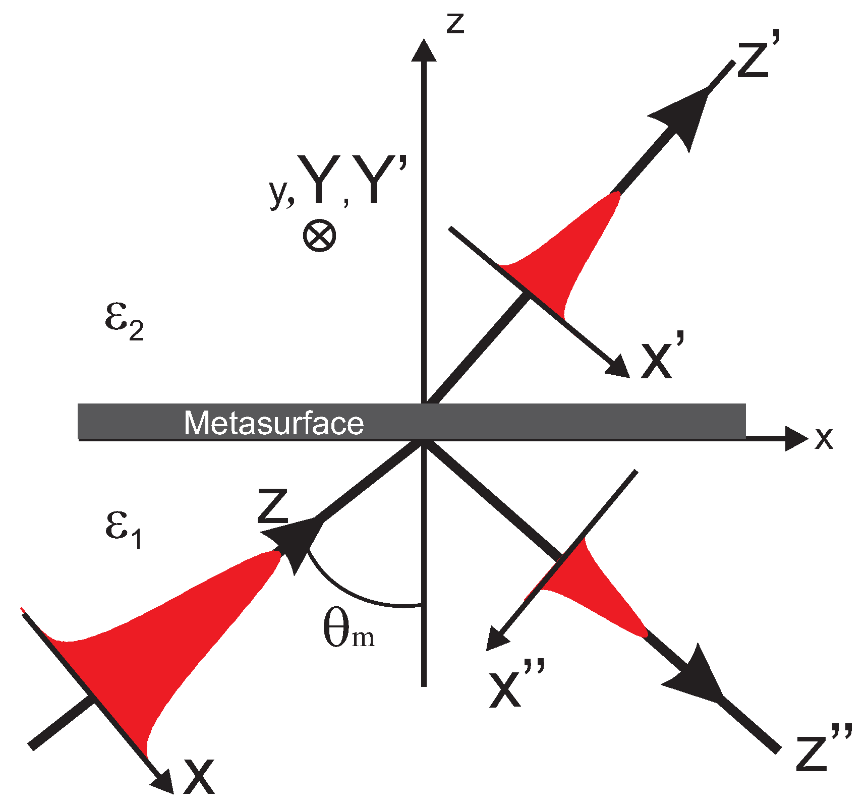
On the one hand, the incident beam (Gaussian, Hermite–Gaussian, Laguerre–Gaussian, etc.) is known through its angular spectrum expansion given in its frame, namely the frame (see Figure 1) corresponding to an average propagation direction along the direction. Generally, the angle of incidence on the metasurface is arbitrary. It is named , as shown in Figure 1.
On the other hand, the monomode modal method, explained in more detail in [14], allows the determination of the transmission and reflection Jones matrices in the basis for any illumination direction characterized by the angle of incidence and the azimuthal angle . For the transmission, we have:
This matrix provides the transmission (amplitude and phase) for any incident plane wave illuminating the metasurface. To determine the transmitted beam, we combine the angular spectrum expansion with the Jones formalism through a variable change allowing the expression of all variables in the metasurface frame () in which the Euler angles and ) are defined (see Figure 2). This implies a variable change to express the angular spectrum in this frame.
First, we need to express the Jones matrix of each plane wave as a function of its wave-vector components through the relations between the latter and the angles and given by:
with , is the tangential component of the wave vector () and is the wave-vector modulus in vacuo.
Second, a basis change from is necessary to determine the transmitted angular spectrum components in the frame of the metasurface:
The operator is the transpose matrix operator, and ℘ is the basis change matrix given by:
The transmitted electric far-field of the whole beam in a plane located at is then calculated by Fourier transform of the transmitted angular spectrum. This leads to the following expression:
Thus, injecting Equation (4) into Equation (3) and the latter into Equation (5) allows the determination of the transmitted beam, providing the knowledge of the angular spectrum of the incident beam .
We propose here to employ this formalism to point out the transmission properties of anisotropic metasurfaces. Consequently, we will define a criterion to evaluate the deviation of the transmitted beam properties from those of an incident plane wave. This is achieved through the determination of three parameters that will help to quantify the transmitted beam properties and are, as well, directly related to experimental considerations. These parameters are:
(1) The transmission coefficient T defined as the ratio of the transmitted total power divided by the incident one.
This parameter is obviously very important and must be maximized () in order to build efficient optical components.
(2) The average phase change induced between the two transverse components of the transmitted beam. This parameter depends on the awaited metasurface properties. In our case, we are dealing with a () plate, so we expect a target value of () between the two transverse components of the electric field directed along the plate axes ( and ). Thus, we define this parameter as:
where the integration is numerically restricted over a surface (S) corresponding to the set of points () in the plane such that . For a Gaussian beam, this corresponds to of the total energy. The frame is related to the transmitted field and is the same as when . Otherwise, a frame change (rotation induced by the light refraction) is required. As defined by Equation (7), the numerical value of the phase shift is determined between and . Thus, we have to be careful when making the sum of all values by assuming a continuous spatial phase change (unwrapping the results before making the summation).
(3) The polarization degree of the transmitted beam P quantified as the spatial average of the polarization degree of each plane wave and given by [15]:
where J is the polarization matrix or the coherency matrix defined by [16]:
is the matrix J determinant.
The value of P is real positive . corresponds to a completely unpolarized beam, while the latter is entirely polarized (linear, circular or elliptical) when . Moreover, we are looking for an anisotropic metasurface that modifies the polarization direction ( plate) or the polarization nature ( plate). In both cases, the transmitted beam must be completely polarized whatever the polarization of the incident beam. This means that the value of P must be close to one.
According to these parameters ( and P) and for anisotropic plates, we define a Figure-Of-Merit () function that corresponds to the total deviation between the response of a plane wave from that of the Gaussian beam by:
where is the phase change expected to be introduced by the anisotropic metasurface and the operator denotes the deviation with respect to the plane wave case. Consequently, we assume that a maximum value of is allowed to recover the plane wave behavior. This value can be seen as an onerous condition. Nevertheless, we will see in the following that this criterion can be easily fulfilled in the case of lossless materials (perfect conductors for instance).
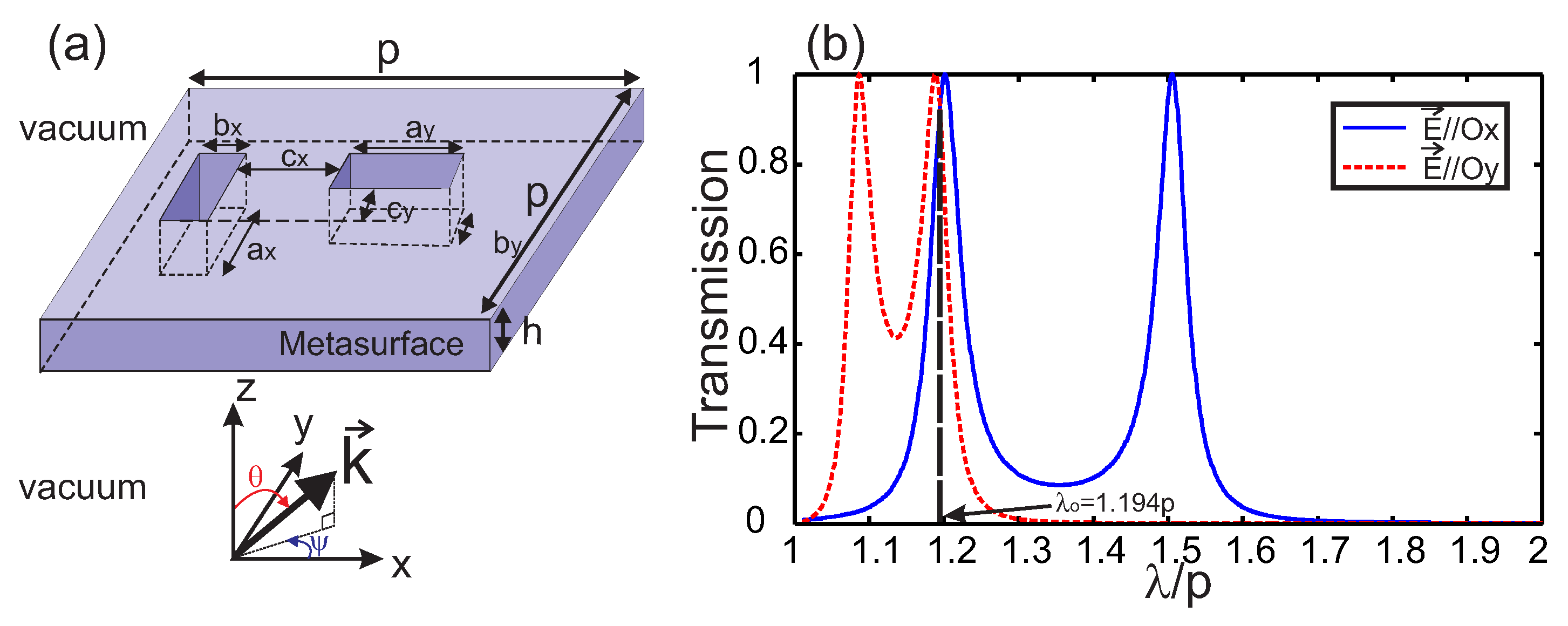
As mentioned earlier, our application deals with the illumination by a finite-size beam of the two anisotropic metasurfaces studied in Figure 4a,b of [14] corresponding to a half-wave and a quarter-wave plate, respectively. The general schema of such an anisotropic metasurface is depicted in Figure 2 and consists of a bi-periodic grating (period p along both x- and y-directions) of two rectangular apertures engraved within an h-thick layer of a perfect electric conductor. All the geometrical parameters are explicitly given in the caption and in the insets of Figure 4a,b of [14]. Nonetheless, they will be reminded below for each case.
The incident beam is set to be a plain Gaussian beam, which is commonly used in experiments. For the three fundamental polarization states (circular, elliptical or linear), its angular spectrum expansion can be expressed in the reference frame related to the metasurface (see Figure 1) by:
where is the Fourier amplitude of the plane wave characterized by its transverse wave vector components expressed in the proper frame of the Gaussian beam (). , and are the same components in the frame of the anisotropic metasurface; is the maximum amplitude of the electric incident field; and is the beam-waist defined as the beam width at of its amplitude . and are given by:
where and a are two parameters that define the polarization state of the incident beam as:
- linear directed along the angle measured from the X-axis with (TEfor and TMfor )
- circular with and
- elliptical with the major to minor axis ratio equal to and (ellipse axes along the x- and y-directions).
This formulation is general and can be applied to any illumination direction provided that the plan of incidence is parallel to . Otherwise, a simple change of variables (rotation around the axis) is needed (see Figure 1).
The first case consists of a half-wave plate where , and (see Figure 2). For an illumination by a plane wave at normal incidence, the transmission coefficient, the phase change and the polarization degree are , and , respectively, at the operation wavelength . As shown in Figure 2b, this wavelength corresponds to an intersection between the transmission spectra of x- and y-polarized incident plane waves.
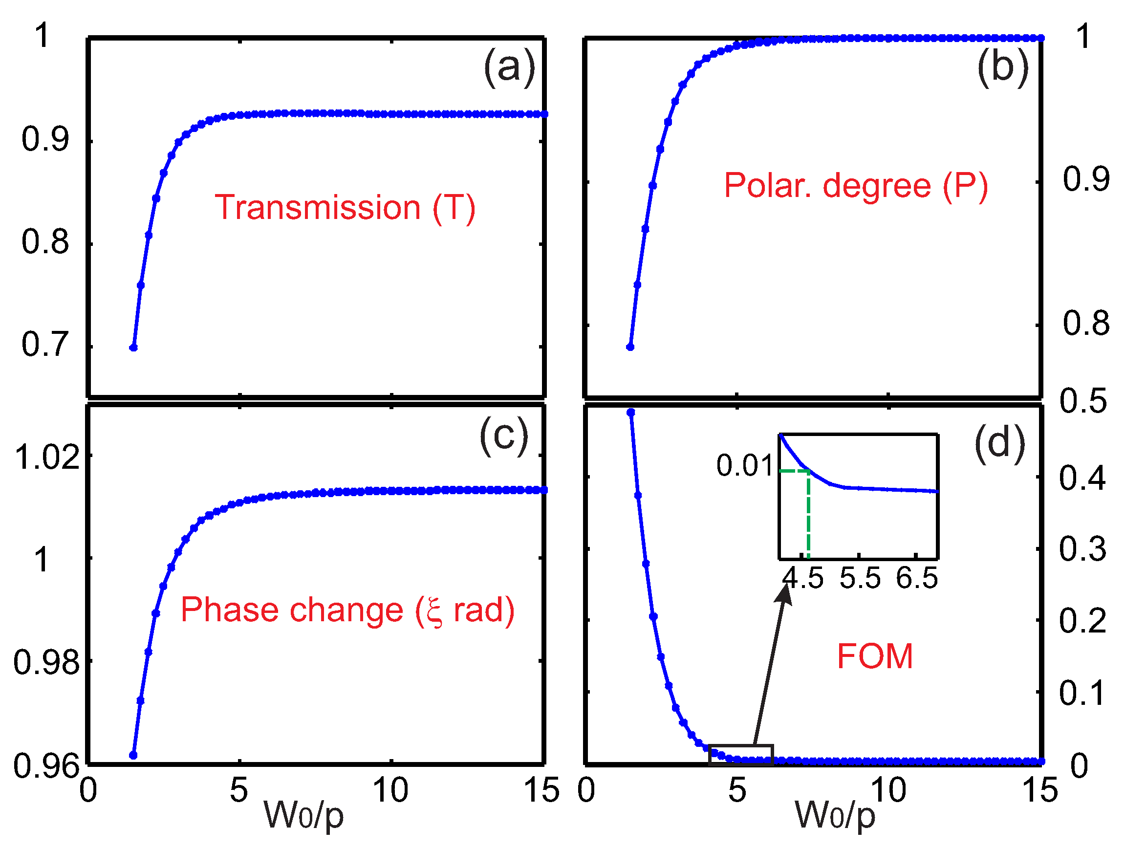
Figure 3 presents the variations of the three parameters T in (a), in (b) and P in (c) and the as a function of the beam-waist when this anisotropic metasurface ( plate) is illuminated by a linearly-polarized Gaussian beam. Due to the structure anisotropy, these parameters will depend on the polarization of the incident beam especially for highly focused beams (small ). To account for this anisotropy, we choose the polarization of the incident beam to be directed along the bisector of by setting 1 and 45 in Equations (12) and (13), respectively.
As we can see from Figure 3a–c, all three parameters tend asymptotically to the value corresponding to a plane wave illumination. A of is reached for a beam-waist (see the inset of Figure 3d). The latter corresponds to a polarization degree of , a phase change of and a transmission efficiency of . This result demonstrates the robustness of the structure with respect to the beam-size. In fact, one might qualitatively expect this outcome because the underlying physical effect (the phase change) is not a collective effect, but results from the excitation of two guided modes inside the apertures with different phase velocity.
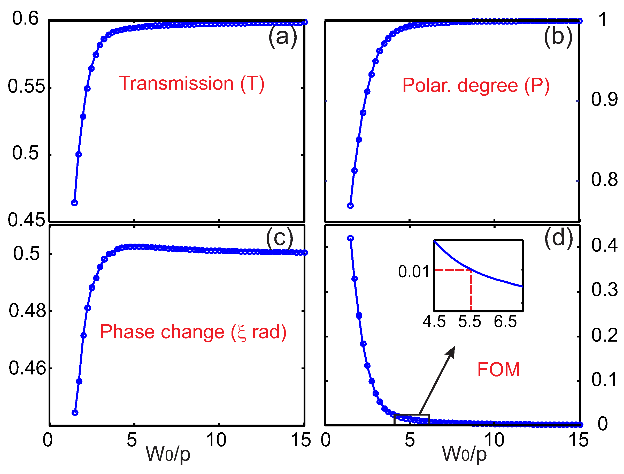
The quarter-wave plate is obtained in [14] by only modifying the dimensions of one rectangular aperture. Thus, after optimizing the transmission coefficient, we set here instead of in that reference. All the other geometrical parameters are kept the same as for the half-wave plate. The operation wavelength is now equal to . This small modification of the parameter leads to a more efficient transmission coefficient of instead of and to and for a plane wave illumination under normal incidence. Figure 4 shows the variations of the three parameters , P and of the as a function of the beam-waist value when this anisotropic metasurface ( plate) is illuminated by a linearly-polarized Gaussian beam. The criterion of is met for a minimum beam-waist of . The condition is quite similar to the half-wave plate’s, demonstrating again the high robustness of such a metasurface to act as anisotropic plates in the domain of THz or microwave.
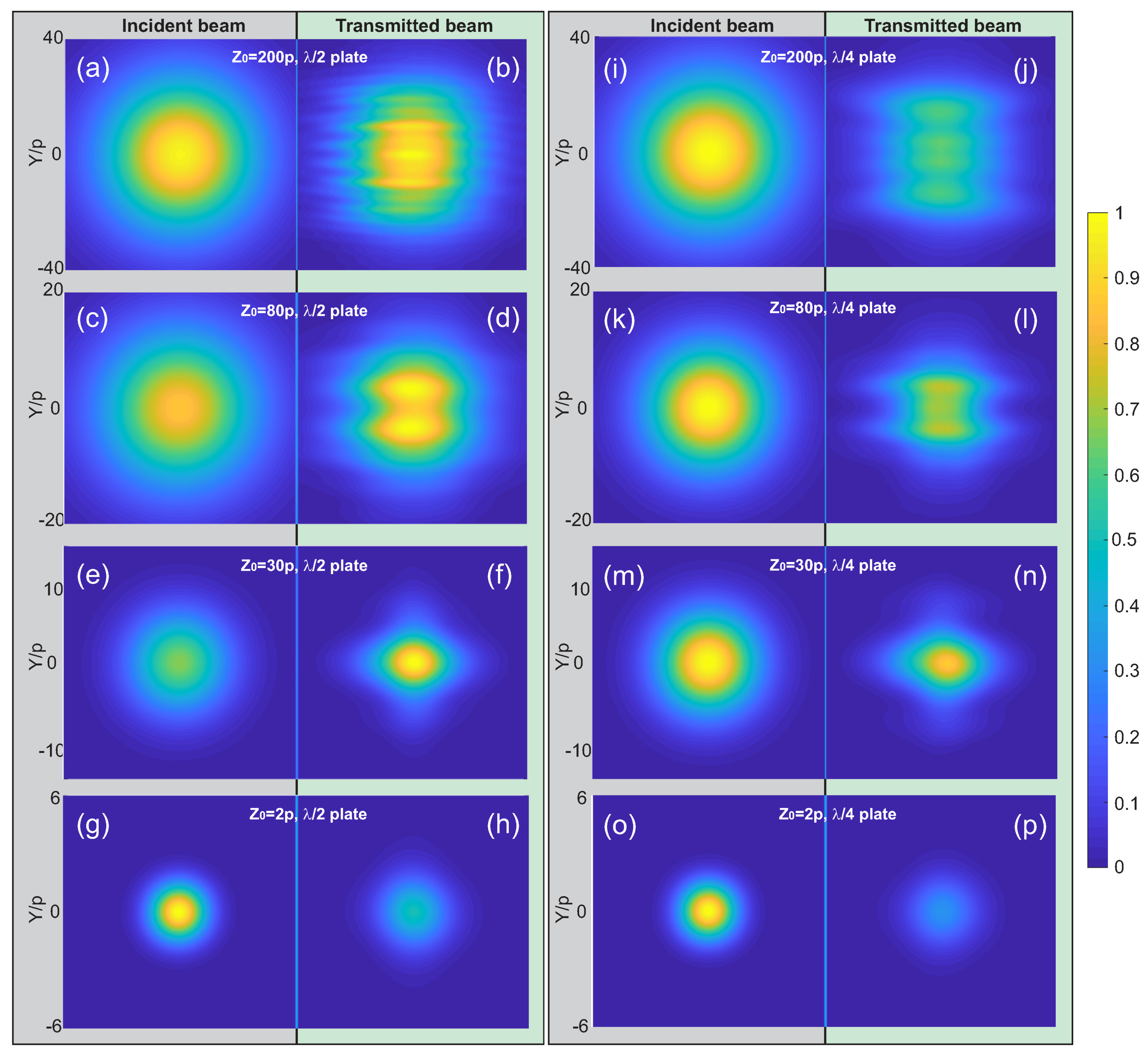
To illustrate the angular filtering effect that can occur for a highly focused Gaussian beam (), we present in Figure 5 the spatial distribution of the incident electric intensity () in comparison with the transmitted electric field intensity () calculated at different distances from the output side of the anisotropic metasurface for a half-wave plate (Figure 5a–h) and for a quarter-wave plate (Figure 5i–p). For both cases, the transmitted beam is distorted and does not exhibit a 2D Gaussian shape. Nevertheless, for certain distances, the transmitted beam provides more intensity (up to a -fold increase as in Figure 5f) at its maximum than the incident beam even if the total whole transmission coefficient is less than one (here, ). This means that the anisotropic metasurface behaves as a focusing lens for distances estimated as approximatively. The same behavior is obtained within the plate except that the transmission coefficient is smaller (see Figure 5i,n). For the two plates, and for distances larger than , the transmitted beam presents more than one maximum resulting from an interference pattern between all the transmitted plane waves after being affected differently (in amplitude) by the structure. Note that the intensity distributions of both incident and transmitted beams were normalized for each value of the distance in Figure 5.
In conclusion, we have developed an original tool that allows us to test the robustness of a metasurface with respect to its transmission, reflection, anisotropy, etc., by adapting the definition of the . This tool is very versatile and can be used to study the effect of any physical parameter such as the angle of incidence, the spatial shape of the beam or the azimuthal angle. The cases of an anisotropic metasurface made in a perfect electric conductor behaving as a or plate are studied to point out the robustness of the transmission properties (efficiency and anisotropy) with respect to beam size. Fortunately, we find that these anisotropic metasurfaces are suitable to operate in both free-propagation and guided-propagation regimes because only a few periods () are needed to recover the full properties of a plane-wave illumination. The FOM can be adapted to the properties of the studied metasurface, replacing, for example, the transmission T by the reflection of the absorption (if energy harvesting is studied) or replacing the phase change by beam steering or chirality (polarization direction angle). The methodology presented here is general and can be applied to beams with arbitrary polarizations and angular spectrum distributions, and it is essential for the design of structures before manufacturing.
Author Contributions
M.B. was involved in numerical simulations, validation and writing of the original draft. A.N. was concerned by the visualization, writing and review editing while F.I.B. made formal analysis, methodology and he supervised the study.
Funding
This research received no external funding.
Acknowledgments
We acknowledge financial support by the EIPHIGraduate School (contract “ANR-17-EURE-0002”). We are grateful to D. Van Labeke for a fruitful discussion and help in the implementation of the monomodal method.
Conflicts of Interest
The authors declare no conflicts of interest.
References
- Martín-Moreno, L.; García-Vidal, F.J.; Lezec, H.J.; Degiron, A.; Ebbesen, T.W. Theory of highly directional emission from a single subwavelength aperture surrounded by surface corrugations. Phys. Rev. Lett. 2003, 90, 167401. [Google Scholar] [CrossRef] [PubMed]
- Popov, E.; Nevière, M.; Enoch, S.; Reinisch, R. Theory of light transmission through subwavelength periodic hole arrays. Phys. Rev. B 2000, 16100–16108. [Google Scholar] [CrossRef]
- Cao, Q.; Lalanne, P. Negative role of surface plasmon in the transmission of metallic gratings with very narrow slits. Phys. Rev. Lett. 2002, 88, 057403. [Google Scholar] [CrossRef] [PubMed]
- Baida, F.I.; Van Labeke, D. Light transmission by subwavelength annular aperture arrays in metallic films. Opt. Commun. 2002, 209, 17–22. [Google Scholar] [CrossRef]
- Przybilla, F.; Degiron, A.; Genet, C.; Ebbesen, T.W.; de Léon-Pérez, F.; Bravo-Abad, J.; García-Vidal, F.J.; Martín-Moreno, L. Efficiency and finite effects in enhanced transmission through suwavelength apertures. Opt. Express 2008, 16, 9571–9579. [Google Scholar] [CrossRef] [PubMed]
- Felbacq, D.; Guizal, B. What is the direction followed by a beam in a photonic medium? Opt. Lett. 2008, 33, 998–1000. [Google Scholar] [CrossRef] [PubMed]
- Boye, R.R.; Kostuk, R.K. Investigation of the effect of finite grating size on the performance of guided-mode resonance filters. Appl. Opt. 2000, 39, 3649–3653. [Google Scholar] [CrossRef] [PubMed]
- Lin, L.; Goh, X.M.; McGuinness, L.P.; Roberts, A. Plasmonic lenses formed by two-dimensional nanometric cross-shaped aperture arrays for fresnel-region focusing. Nano Lett. 2010, 10, 1936–1940. [Google Scholar] [CrossRef] [PubMed]
- Della Giovampaola, C.; Engheta, N. Digital metamaterials. Nat. Mater. 2014, 13, 1115–1121. [Google Scholar] [CrossRef] [PubMed] [Green Version]
- Kivijarvi, V.; Nyman, M.; Karrila, A.; Grahn, P.; Shevchenko, A.; Kaivola, M. Interaction of metamaterials with optical beams. New J. Phys. 2015, 17, 063019. [Google Scholar] [CrossRef] [Green Version]
- Verslegers, L.; Catrysse, P.B.; Yu, Z.; White, J.S.; Barnard, E.S.; Brongersma, M.L.; Fan, S. Planar lenses based on nanoscale slit arrays in a metallic film. Nano Lett. 2009, 9, 235–238. [Google Scholar] [CrossRef] [PubMed]
- Khorasaninejad, M.; Chen, W.T.; Oh, J.; Capasso, F. Super-dispersive off-axis meta-lenses for compact high resolution spectroscopy. Nano Lett. 2016, 16, 3732–3737. [Google Scholar] [CrossRef] [PubMed]
- Roberts, A. Beam transmission through hole arrays. Opt. Express 2010, 18, 2528–2533. [Google Scholar] [CrossRef] [PubMed]
- Baida, F.I.; Boutria, M.; Oussaid, R.; Van Labeke, D. Enhanced-transmission metamaterials as anisotropic plates. Phys. Rev. B 2011, 84, 035107. [Google Scholar] [CrossRef]
- Wolf, E. Coherence properties of partially polarized electromagnetic radiation. Nuovo Cim. 1959, 13, 1165–1181. [Google Scholar] [CrossRef]
- Al-Qasimi, A.; Korotkova, O.; James, D.; Wolf, E. Definitions of the degree of polarization of a light beam. Opt. Lett. 2007, 32, 1015–1016. [Google Scholar] [CrossRef] [PubMed]
Figure 1.
Schematic of the model with the different frames involved in the theoretical model: the metasurface frame, the incident beam frame, the reflected beam frame and the transmitted beam frame. is the angle of incidence.
Figure 1.
Schematic of the model with the different frames involved in the theoretical model: the metasurface frame, the incident beam frame, the reflected beam frame and the transmitted beam frame. is the angle of incidence.

Figure 2.
(a) Schema of a unit cell of the anisotropic metasurface. The rectangular apertures are engraved in a perfectly electric conductor layer of thickness h. The two rectangle dimensions are different in order to induce artificial anisotropy. (b) Typical transmission spectra for the two orthogonal polarization states along and when in the case of an incident plane wave.

Figure 3.
Variations of (a) the transmission efficiency T, (b) the polarization degree P, (c) the phase change and (d) the defined by Equation (10) in the case of the half-wave plate operating at as a function of the illumination Gaussian beam size . The beam is impinging the structure under normal incidence and is polarized at 45 from the x-axis in order to get transmission across the two perpendicular rectangles. The angular spectrum expansion of the beam is described with harmonics. The inset in (d) corresponds to a zoom made around .

Figure 4.
Same study as in Figure 3, but for the quarter-wave plate operating at .
Figure 4.
Same study as in Figure 3, but for the quarter-wave plate operating at .

Figure 5.
Incident (a) and transmitted electric field intensities in a transversal plane located at from the anisotropic metasurface in the case of (b) and (c) plates. Figures (a,b) to (g,h) refer to the plate while figures (i,j) to (o,p) are attributed to the plate. The total dimension of each figure is . The waist of the beam is located at , and its value is fixed to .

© 2018 by the authors. Licensee MDPI, Basel, Switzerland. This article is an open access article distributed under the terms and conditions of the Creative Commons Attribution (CC BY) license (http://creativecommons.org/licenses/by/4.0/).
Share and Cite
MDPI and ACS Style
Boutria, M.; Ndao, A.; Baida, F.I. Quantification of the Transmission Properties of Anisotropic Metasurfaces Illuminated by Finite-Size Beams. Appl. Sci. 2018, 8, 2001. https://0-doi-org.brum.beds.ac.uk/10.3390/app8102001
AMA Style
Boutria M, Ndao A, Baida FI. Quantification of the Transmission Properties of Anisotropic Metasurfaces Illuminated by Finite-Size Beams. Applied Sciences. 2018; 8(10):2001. https://0-doi-org.brum.beds.ac.uk/10.3390/app8102001
Chicago/Turabian StyleBoutria, Mohamed, Abdoulaye Ndao, and Fadi I. Baida. 2018. "Quantification of the Transmission Properties of Anisotropic Metasurfaces Illuminated by Finite-Size Beams" Applied Sciences 8, no. 10: 2001. https://0-doi-org.brum.beds.ac.uk/10.3390/app8102001
Note that from the first issue of 2016, this journal uses article numbers instead of page numbers. See further details here.