Pursuing High Quality Phase-Only Liquid Crystal on Silicon (LCoS) Devices
by
 ,
,
Huang-Ming Philip Chen
1,*, 
Jhou-Pu Yang
1,
Hao-Ting Yen
1,
Zheng-Ning Hsu
1,
Yuge Huang
2 and
Shin-Tson Wu
2 1
Department of Photonics, College of Electrical and Computer Engineering, National Chiao Tung University, Hsinchu 30010, Taiwan
2
College of Optics and Photonics, University of Central Florida, Orlando, FL 32816, USA
*
Author to whom correspondence should be addressed.
Appl. Sci. 2018, 8(11), 2323; https://0-doi-org.brum.beds.ac.uk/10.3390/app8112323
Submission received: 31 October 2018
/
Revised: 12 November 2018
/
Accepted: 14 November 2018
/
Published: 21 November 2018
(This article belongs to the Special Issue Liquid Crystal on Silicon Devices: Modeling and Advanced Spatial Light Modulation Applications)
Abstract
:Fine pixel size and high-resolution liquid crystal on silicon (LCoS) backplanes have been developed by various companies and research groups since 1973. The development of LCoS is not only beneficial for full high definition displays but also to spatial light modulation. The high-quality and well-calibrated panels can project computer generated hologram (CGH) designs faithfully for phase-only holography, which can be widely utilized in 2D/3D holographic video projectors and components for optical telecommunications. As a result, we start by summarizing the current status of high-resolution panels, followed by addressing issues related to the driving frequency (i.e., liquid crystal response time and hardware interface). LCoS panel qualities were evaluated based on the following four characteristics: phase linearity control, phase precision, phase stability, and phase accuracy.
1. Introduction
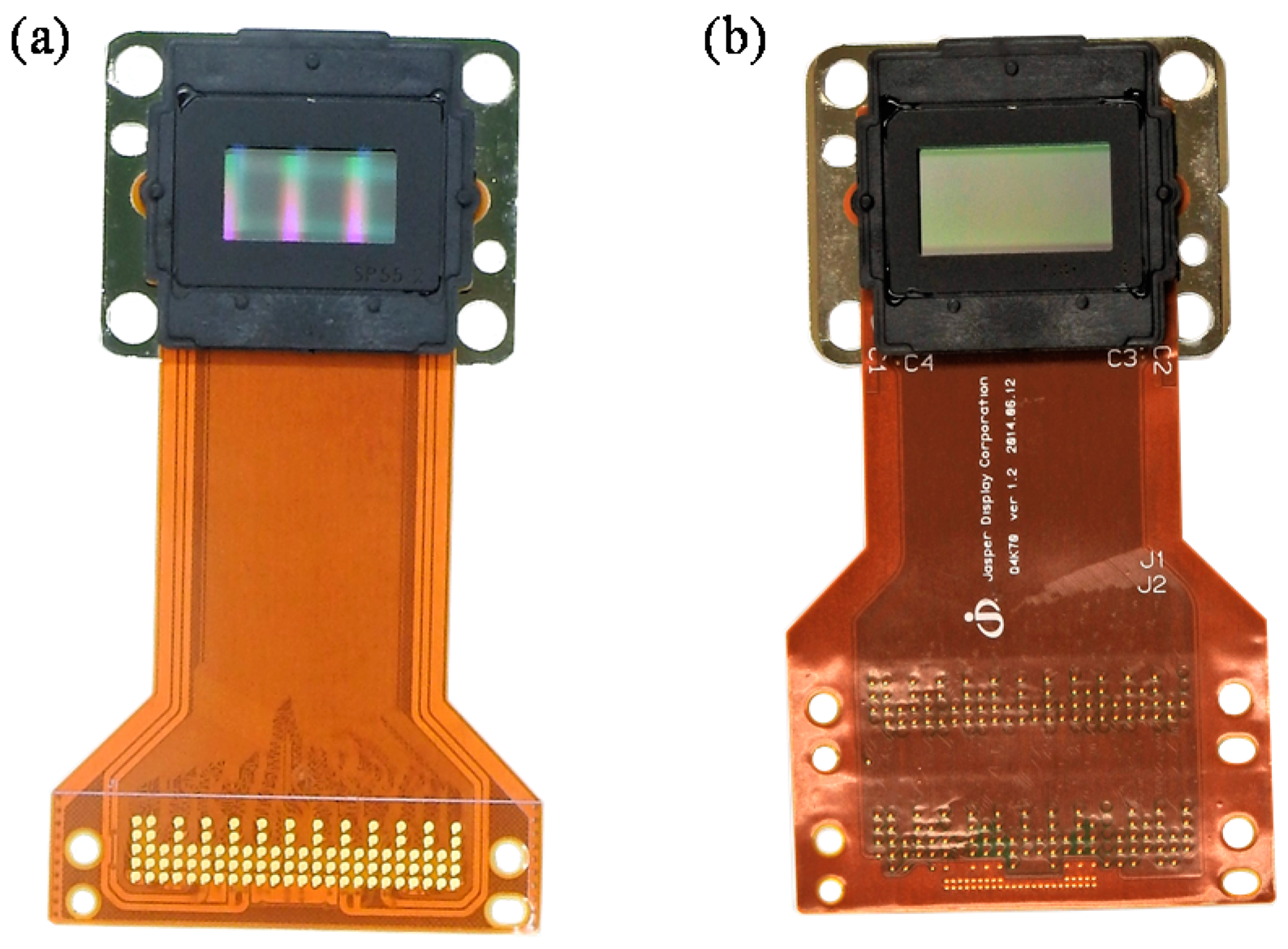
Photo-activated liquid crystal on zinc-sulfide (ZnS) [1], cadmium-sulfide (CdS) [2], and active-matrix addressed liquid-crystal-on-silicon (LCoS) [3] were first introduced by Hughes Research Laboratories for display applications in the early 1970s. Later, this approach was extended to the reflective spatial light modulator (SLM) [4,5]. The LCoS-based SLM panel resolution increased from 16 × 16 to 176 × 176 pixels, as was reported by the University of Edinburgh (Edinburgh, UK), in the period 1986–1989 [6]. In 1993, resolution was further increased to a 254 × 254 pixel array by DisplayTech (now CITIZEN FINEDEVICE (CFD) Co., LTD, Yamanashi, Japan). Their panel adopted the fast-switching ferroelectric liquid crystal (FLC) and implemented the field-sequential color system to generate a full color display. The ferroelectric-LCoS remains their distinctive product until today [7]. The projection display technology using LCoS as the core optical engine is not able to compete with digital micro-mirror device (DMD) technology with a resolution of 720p due to the cost structure. However, a high-resolution LCoS panel with a small pixel size can be commercialized owing to the advancement in integrated circuit (IC) technology during the past 10 years. Since 2000, LCoS has evolved from 720p to not only 2K1K Full High Definition (FHD) but also 4K2K resolution. Photos shown in Figure 1 of high-resolution display products are provided by Jasper Display Corp.
Holographic near-eye displays using LCoS as a display panel opened a new era for virtual and augmented realities. Oculus Rift and HTC VIVE announced and demonstrated compelling 3D virtual reality (VR) experiences using JD5552 LCoS-SLM (Jasper Display Corp.; Hsinchu, Taiwan R.O.C.) in 2016 [8]. Microsoft demonstrated the HoloLens, its first self-contained augmented reality (AR) device, using PLUTO LCoS-SLM (Holoeye Photonics; AG, Berlin, Germany) in the same year [9]. In addition to Jasper Display Corp. and Holoeye Photonics, there are other worldwide providers of LCoS micro-displays, such as Hamamatsu Photonics, Meadowlark Optics, Santec Corp., and Himax. Each company has its own focus within its products. Jasper Display Corp. has its own digital drive 2K1K and 4K2K panels with corresponding drivers. Holoeye Photonics has a distinctive solution for 60 Hz 4K-SLM and computer-generated hologram (CGH) information input software development kit (SDK) interface design [10]. Hamamatsu provides pure-phase SLM solutions with high linearity and precision. It also provides SLMs for high-power laser applications [11]. Meadowlark Optics features the analog drive LCoS-SLM solution, which has a fast liquid crystal (LC) response time, a near-millisecond response, and a near-kHz picture frame rate [12]. Santec’s LCoS-SLM phase modulator can provide ultra-high flatness (i.e., high phase precision) and a 10-bit linear curve [13]. Table 1 summarizes their unique products.
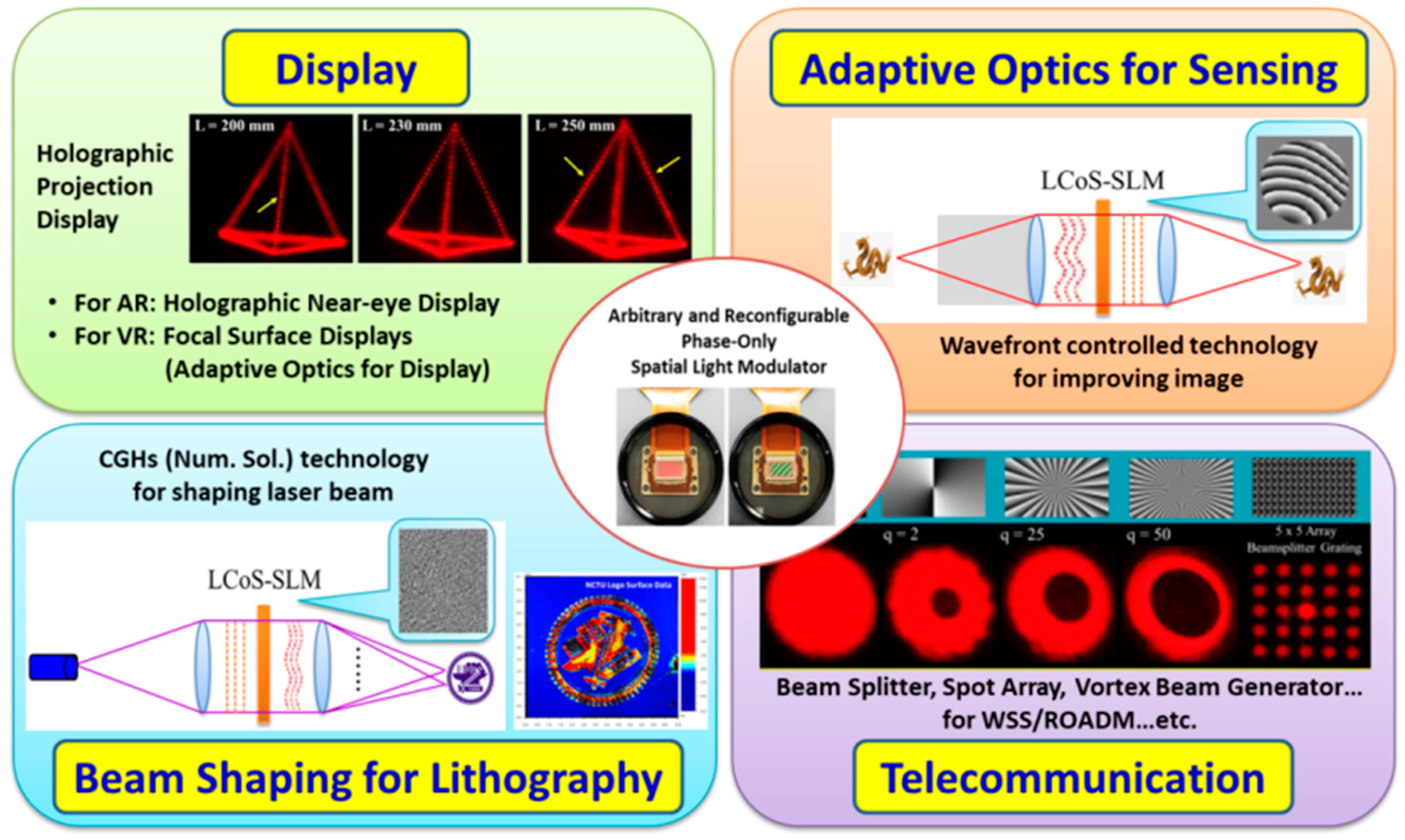
A phase-only spatial light modulator can be used as a key optical element for displays, adaptive optics for sensing, lithography, and telecommunication, as shown in Figure 2. The linearity of phase modulation, response time, phase precision, and phase stability are key characteristics for appraising or selecting phase-only LCoS-SLM panels for the applications designed. However, it is difficult to obtain a single LCoS possessing all the desired features for all applications. Their specification and performance optimization are application-driven. For example, response time is the current limitation in a holographic display. It may be more important than phase stability, because an excellent holographic image can still be achieved using a well linearly calibrated and high-phase precision LCoS-SLM panel. On the other hand, the phase stability of the LCOS-SLM is a vital property in the field of optical communication, because an instantaneous disturbance resulting from an unstable phase may cause misjudgment of the transmitted information [14]. Compared to fast response time, phase stability is much more important for optical communication applications.
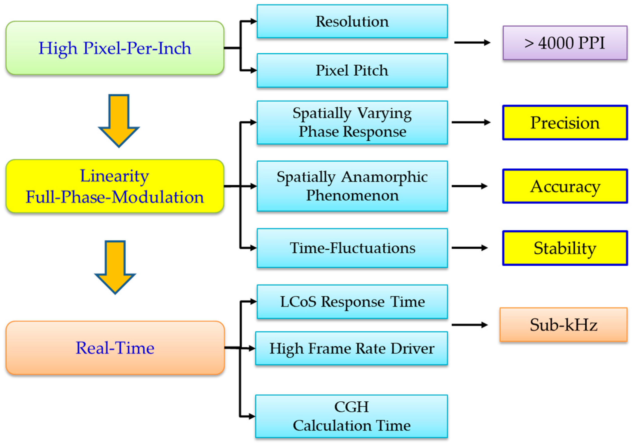
Other applications may require precise phase modulation, such as processing of laser materials [15,16] or controlling the wave front for an image enhancement application [17]. We summarize the quantitative assessment indicators for the LCoS-SLM panels in Figure 3. The high-resolution panel is a trend for future phase modulation. The linearity of phase modulation is not only convenient for data acquisition, but also fulfills linear modulation in the diffraction equations derived from the scalar diffraction theory. The phase precision, phase stability, and phase accuracy can be further evaluated based on a linear phase calibrated panel. Real-time modulation depends on the LC response time, driver latency, and the calculation time of CGHs. In this review, we reveal current progress and approaches in designing and developing high-quality phase-only LCoS-SLM with the assessment of following criteria: panel resolution, driving frequency (LC response time and hardware interface), phase linearity control, phase precision, phase stability, and phase accuracy.
2. High Resolution and High Pixel-Per-Inch (PPI)
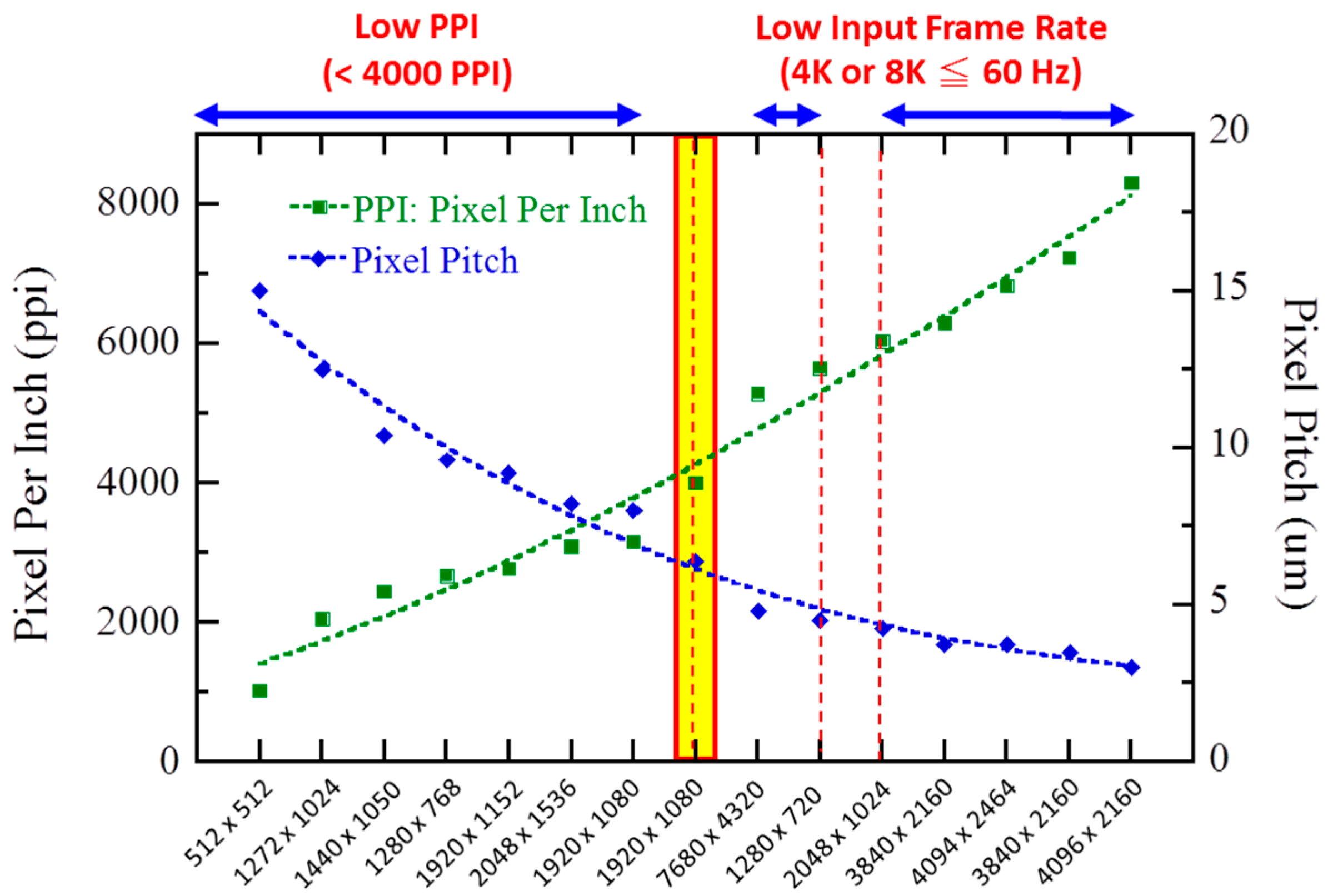
Achieving higher resolution with higher pixel density and smaller pixel pitch is a continuous goal of LCOS micro-displays, especially for near-eye VR display applications [18]. For holographic AR, higher diffraction, or larger image projection, a high-resolution panel is also required [19,20,21]. The small pixel size enables a large diffraction angle, and a large panel with high resolution empowers finer details of the projected image. The current resolution density in pixel per inch (ppi) and the pixel pitch of commercial LCoS-SLM panels are summarized in Figure 4. In particular, panels with high ppi (>5000) 4K2K or 8K4K LCoS possess a low input frame rate (≤60 Hz) or limited driving voltage (<3.3 V). In general, it is difficult to maintain a frame rate of 60 Hz in a 4K2K panel [22].
Several approaches to achieve high frame rates in high-resolution panels (≥4000 ppi) have been realized recently. Yang et al. demonstrated 4000 ppi in a 0.55-inch 1920 × 1080 IC backplane with a pixel pitch of approximately 6.4 μm [23]. Abeeluck et al. demonstrated a digital drive LCoS micro-display with a pixel pitch of 3 μm and a high fill factor of 93.5% in resolutions from 1080p to 4K [24]. Such a small panel size can be easily integrated into an optical machine or an embedded system. The advantage of a panel with small pixels is that a larger diffraction angle can be obtained. In addition, two commercial products listed in Figure 4—the 0.26 inch 1280 × 720 resolution (Holoeye HED2200) and the 0.37 inch 2048 × 1024 resolution IC back panels (Himax Display; Tainan, Taiwan R.O.C.)—are suitable for panels with a large diffraction angle, while maintaining a high picture frame rate.
3. Switching Time for Phase Modulation
There are four major issues for holographic display applications: (1) the slow liquid crystal response time; (2) the small field of view (FoV); (3) the laser speckle effect degrading the image quality when using lasers as a backlight unit; and (4) a reduction in the frame rate for achieving field-sequential color displays [25]. There are many studies where the aforementioned issues have been addressed, such as: (1) 3–4 ms phase-only panel response time of thin cell gap at λ = 633 nm to reduce the dynamic reconstruction holographic image blur [26]; (2) the time-division multiplexing method to increase the FoV [27]; and (3) reduction of the speckle effect in image projection using temporal averaging techniques [28]. The ultimate turn-key solution to these challenges is the SLM panel with a sub-millisecond response time and a sub-kHz input frame rate.
Ferroelectric liquid crystal (FLC) modulators [29,30] and digital micro-mirror devices (DMD) [31] are two commercial spatial light modulators capable of achieving sub-millisecond response times. Significant quantization noise lowers the diffraction efficiency due to binary phase modulation. Several approaches have been proposed to achieve a fast response time, such as dual frequency LC (DFLC) [32], polymer network LC [33,34], and polymer-stabilized blue phase LC [35]. High driving voltage (greater than 10 V) and light scattering in the visible region are the two major drawbacks of these LC material systems. In addition, limited driving voltage in a high-resolution backplane often results in a slower LC response time. Lately, Wu’s group reported that an average phase-to-phase response time of ~2 ms can be achieved using high Δn LCs in a thin cell gap of 1.7 μm at an operating voltage of 5 V at 40 °C [36,37]. The reported LCs can be used with 240 Hz frame rate without complicated overdrive or undershoot circuitries. Additionally, the effective birefringence of liquid crystals slightly decreases when the cell gap is below 1.8 μm due to the strong surface boundary effect of the alignment layers [38]. Thus, a higher birefringence LC material may be needed in order to achieve the calculated effective birefringence in an ultra-thin cell for a fast-response LCoS phase modulator. Thalhammer et al. utilized the overdrive approach to boost the LC response time to 1–2 ms for a low-resolution panel (256 × 256) with 500 Hz input frame rate and ~1.6 kHz data frame rate [39]. However, the input frame rate dropped to 30 Hz when using a High Definition Multimedia Iinterface (HDMI) controller in their high resolution (1920 × 1152) LCoS-SLM. Holoeye Photonics presented a HDMI 2.0 Field Programmable Gate Array (FPGA) driver to achieve 1920 × 1080 resolution (4000 ppi) for 240 Hz and 720 Hz data frame rates for high performance 3D sensing systems [40]. However, the driver scheme cannot support their LETO phase modulator (also 4000 ppi) due to the slow LC response time, which is not comparable with the sub-kHz input frame rates. Meadowlark Optics launched a new 1.8 ms response time phase-only 1920 × 1152 pixels (~2764 ppi) LCoS-SLM without overdrive. In 2018, the maximum frame rate reached has been 714 Hz by using a PCIe controller [41]. In the same year, Chen’s team announced their PCU-3-01 LCoS-SLM, capable of reaching 1.6 ms at 45 °C. The panel can be driven at 240 Hz input frame rate with the OCM-ASIC SDK driver (Jasper Display Corp.) and at 720 Hz data frame rate by using an HDMI controller [17]. Higher resolution of 4K2K or 8K4K LCoS panels (greater than 5000 ppi) is limited by low input frame rate (≤60 Hz) and low driving voltage (<3.3 V). Future electronic hardware updates are required to achieve full phase modulation. In summary, less than 2 ms LC response time is available for high-resolution LCoS-SLM panels, but the controller still needs to be updated to reach a frame rate over 500 Hz. The fast LC response of full phase modulation, high input frame rate, and driver interface are equally important to enable next-generation LCoS for holographic displays.
4. Phase Linearity
Phase linearity correction is an essential step for phase modulation panels. This is similar to the gamma correction for linear amplitude modulation in LC displays [42], but is a more complex process, covering the full 2 π radians phase. The linear phase response is a key criterion for satisfying computer-generated hologram (CGH) patterns calculated on the basis of the iterative Fourier transform algorithm (IFTA) or Fresnel (near-field)/Fraunhofer (far-field) diffraction equations, derived from scalar diffraction theory. The linear material for modulation is the main assumption of the theory. However, the intrinsic electro-optical response of liquid crystal is nonlinear. The measured intensity curve can be converted to phase based on following equation:
where I/I0 is the normalized intensity, χ is the angle between the polarizer and the analyzer, ϕ is the angle between the LC director and the polarizer, and δ is the phase retardation. A nonlinear phase curve containing the sine or cosine function is tuned to a linear phase response using the look-up table (LUT) method [43]. The CGH simulation cannot correctly project its result without linear correction of LCoS-SLM. To solve this issue, “Linear Phase Calibration” is the first step for LCoS-SLM. The ease of calibration is closely related to the driving scheme in the control circuit. The digital driving scheme uses pulse width modulation (PWM) to generate the gray scale that can be divided into finer 0- and 1-bit planes. This makes programming of linear calibration much easier than the backplane using analog driving scheme. The average phase accuracy error (APAE%) and the root mean square (RMS) methods can be applied to evaluate the phase linearity of all gray levels:
where GL is gray level, LUT is look-up table, and δ is the measured phase value. Let us take our PCM-2-01-633 LCoS-SLM panels with 1920 × 1080 resolution and 60–144 Hz picture frame rate as an example. A design with high-programmed pulse switching at ΔV = 5 V of the IC backplane was applied to reach a liquid crystal response within 4 ms. The phase linearity can be adjusted down to 1.08% (APAE%) and 0.024 π radians (RMS). In general, achieving ideal phase linearity in an analog driving LCoS-SLM is more difficult than in a digital driving scheme without additional optical compensation [44]. The Meadowlark Optics LCoS-SLM can achieve high-speed response (2–5 ms) while maintaining a certain degree of linearity in a low-resolution panel (256 × 256) using analog driving [45], but not in their higher resolution (HSP512 and HSP1920) LCoS panels. The LCoS panel with an analog drive from Hamamatsu Photonics can achieve ultra-high linearity (0.03 π radians (RMS)) at a lower resolution (792 × 600) and 60 Hz picture frame rate. However, to maintain ultra-high phase linearity, a thicker LC cell gap and lower operation voltage are required. The drawback of this setup is a slower response time (>30 ms).
5. Phase Precision
Besides the linear phase response in all gray scales, another issue is the phase precision over the entire active area. Phase precision has been discussed in many different forms, such as “spatially varying phase response” (SVPR) [46], “spatially resolved phase response” (SRPR) [47], “multipoint phase modulation” [48,49,50,51], “uniformity metrology” [52,53,54,55], “wavefront distortion” [56], “optical flatness”, etc. The phase precision quality of an LCoS-SLM panel can be defined by using the above-mentioned evaluation methods. The current four major LCoS SLM manufacturers provide the following phase precision standards: (1) the latest 4K2K GAEA-2 from Holoeye Photonics—the optical flatness can be adjusted from λ/6.6 to λ/10 (RMS) after phase compensation; (2) the high phase precision LCoS panel from Hamamatsu Photonics—the phase precision has to be λ/50 mean standard deviations (mSTD) after phase compensation; (3) the latest HSP1920 from Meadowlark Optics—the phase precision can be adjusted from λ/7 to λ/20 (RMS); and (4) the latest SLM-200 from Santec Corp.—its wavefront distortion is greater than λ, but can be reduced to λ/40 after compensation. We adopt the mSTD from 256 (8 bits) gray scales to evaluate the phase precision before compensation, defined as:
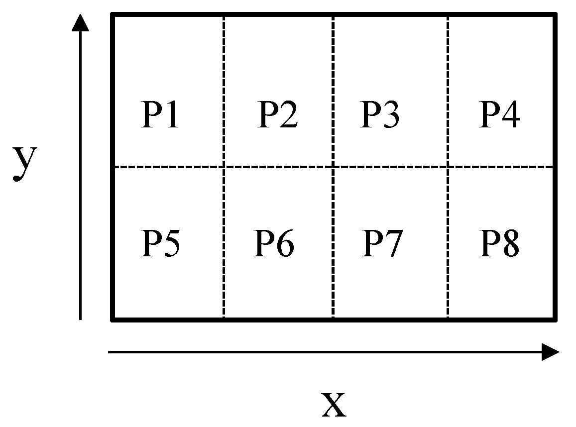
where δ is the phase measurement based on the LUT at different gray levels, and x and y refer to the specific area measured over the whole panel as shown in Figure 5. Fewer or more sections of mxy is dependent on the beam size or characterization method.
The following formula represents various factors that affect phase modulation:
Factors that can affect the output wavefront (δtotal) of an SLM can be attributed to modulated terms (Δδ) and non-modulated terms (δo). The modulated terms (Δδ) can be rewritten as follows to specify the effects on LC birefringence (Δn) and cell gap (d):
In the non-modulated term, unevenness may arise due to the surface flatness of LCoS IC-backplane after the chemical mechanical polishing (CMP) process [57], the surface flatness of LC alignment layer, or other components like Indium Tin Oxide (ITO)cover glass. The main source of imprecision of the SLM phase is the modulation term. The three factors can be recognized across the entire LCoS panel (x, y) as following: (1) the cell gap uniformity (d); (2) the temperature effect (T) of the SLM panel, and (3) the voltage uniformity (V) from pixels. The uniformity of the LC layer is the most important parameter for the output wavefront. It requires a high assembly precision to control the cell gap uniformity error of ~1% over the entire active area in the liquid crystal assembly (LCA) process (assuming no internal damage to the IC backplane during LCA). This becomes more difficult if the cell gap is below 1.6 μm. The problem of rising temperature may be caused by either a high-power light source or the thermal effect from IC backplane. The output wavefront unevenness could result from non-uniform backplane temperature due to poor heat dissipation design in the optical system. This effect can be minimized if the operating temperature of the LCoS-SLM backplane can be evenly controlled at a constant temperature. Most of the problems that affect the phase precision of the panel are mainly due to the non-uniform LC cell gap and the uneven output voltage at each pixel. The non-uniform voltage occurs mainly on the analog drive’s LCoS panel because the analog drive uses a dynamic random access memory (DRAM) capacitive method to supply different voltages for different gray levels. By contrast, different gray levels in the LCoS panel with digital drive are generated by the static random access memory (SRAM) to determine the voltage difference (ΔV = Vw − Vb, in which Vw is Vwhite, and Vb is Vblack) in conjunction with different time sequences (namely, pulse width) driving design. As a result, the digital driving scheme has the DC balance characteristic, which has fewer problems with voltage non-uniformity. In addition, the data addressing speed of the digital drive chip is very fast (ns ~ μs). This will not be the main cause of the unevenness and inaccuracy of the spatial phase, even if the digital driver adopts the time sequential driving scheme. The major problem associated with digital time sequential driving design is “phase flicker”, which will be discussed in more detail in Section 6, which is devoted to phase stability.
The default setting may be off or not satisfied for the design applications after receiving the SLM panel from the venders. As a result, phase linearity calibration and phase precision compensation have been hot topics for SLM research. Various reported phase compensation methods can be roughly divided into two categories: one is by electronic compensation method, and the other is by optical compensation method. Most of the LCoS-SLM driver board settings are not open to users. As a result, the electronic compensation method may only be available to original manufacturers. Most SLM users applied optical algorithms to achieve high-quality wavefronts by correcting wavefront aberration using the Zernike polynomials algorithm. The algorithm can correct the most serious wavefront distortions, but is limited to a circular aperture due to the principle of Zernike polynomials. The compensation is inappropriate for square or rectangular apertures, such as the LCoS-SLM panel. For example, P512 series products from Boulder Nonlinear Systems (BNS), have wavefront distortion value of 1.2 λ before compensation. They can be optically compensated to λ/4 [58] but not up to the high phase precision standard (<λ/50). Their latest product, HSP1920, adopted electronic compensation for square sub-apertures in 2018. The wavefront distortion value can be greatly enhanced from λ/7 to λ/20 (RMS). Even though Zernike polynomials are not fully applicable to a square aperture to correct high-end aberrations, other research teams continue to improve or seek alternative optical algorithms for phase compensation. Xu et al. proposed to use the Zernike polynomials method plus least mean square fitting to adjust the LCoS uniformity of 1 × 12,288 pixels. Their result suggested that the RMS value of the inherent wave-front distortion can be suppressed approximately to λ/34 [59]. Engström et al. proposed using the principle of 7th-order 3D polynomials to compensate for the phase uniformity of the HSPDM512 product of BNS in the form of 64 × 64 pixels. It uses the peak-to-valley value as an evaluation method for wavefront distortion. It was shown that the maximum error amount can be corrected from 0.6–0.8 π to 0.3 π [46]. This method effectively corrects the error, but increases the overall computation time for the CGH phase compensation. The computation time can be accelerated up to 0.13 ms per CGH by using the Compute Unified Device Architecture (CUDA) encoding program. This result may not affect real-time operation on its panel, but will significantly prolong the computation time when using higher resolution (>4K2K) SLM with a high frame rate (>240 Hz). Either internal compensation using a chip circuit, or external compensation using an FPGA or Application Specific Integrated Circuit (ASIC) driver board are the better solutions to avoid extra load of computing the compensation algorithm in CGHs. In addition, it is possible to divide the active area into several unit blocks. The phase correction look-up table of each unit block (LUT(x, y)) can be performed individually to achieve high-precision modulation of the wavefront.
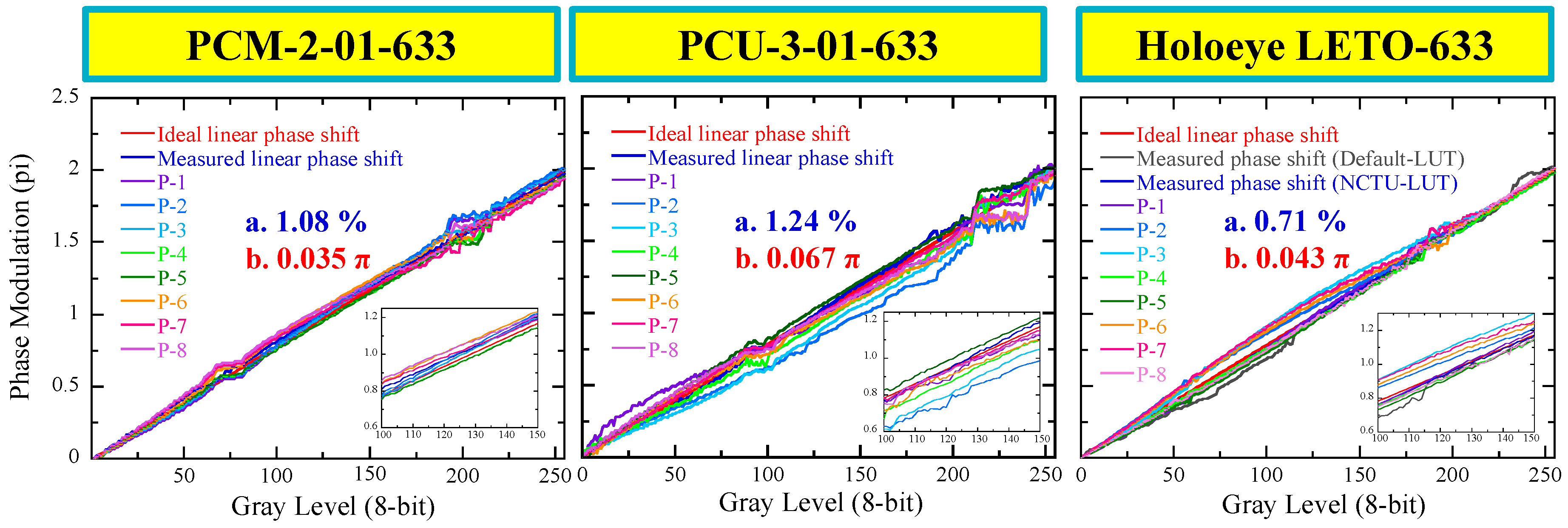
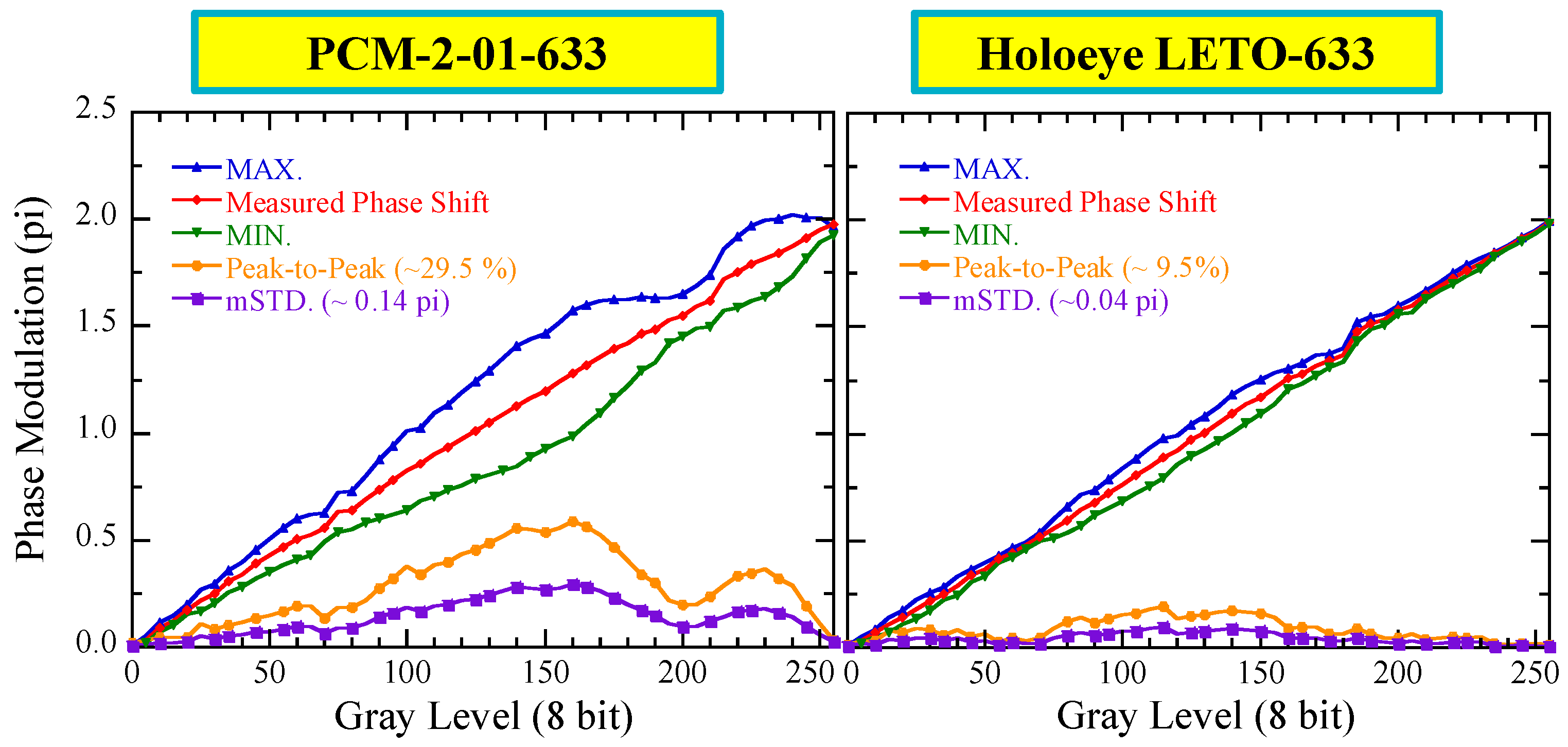
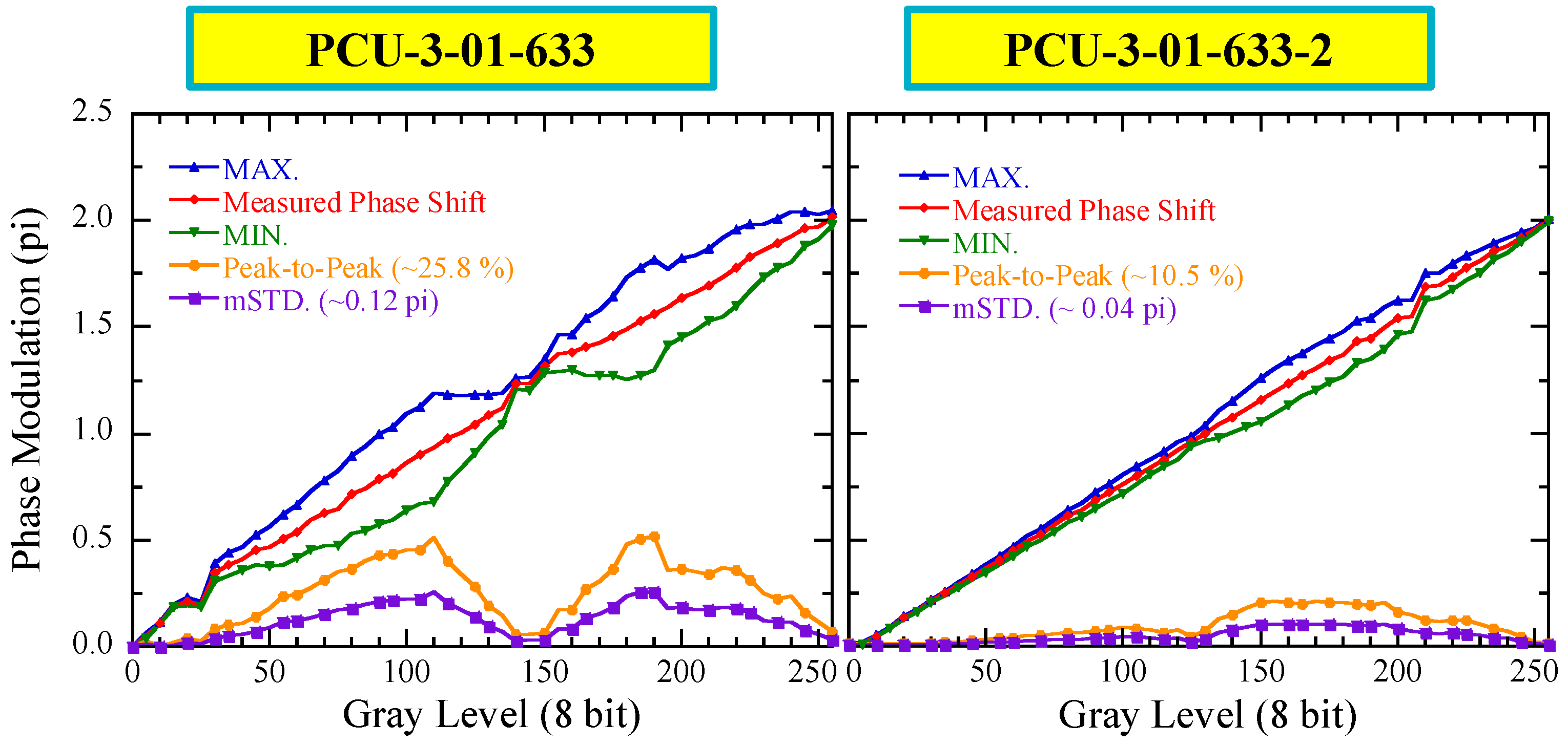
To demonstrate the phase precision measurements, we compare three LCoS-SLM at λ = 633 nm, PCM-2-01-633, PCU-3-01-633 (prepared in house), and LETO (Holoeye), under the same digital driving scheme at a controlled temperature T = 35 °C. The phase linearity errors (APAE%) under the global LUT of the PCM-2-01 and PCU-3-01 are 1.08% and 1.24%, respectively. The phase linearity error (APAE%) of the LETO panel can be tuned from 2.20% to 0.71% by using our driving calibration instead of the default setting for production. The spatially varying phase responses (SVPR) of the three different LCoS-SLM panels are measured after the phase linearity error of the global phase response is adjusted to around 1.0%. On each LCoS-SLM panel, a phase shift is estimated from eight different sections (P-1 to P-8 as shown in Figure 5) covering the entire panel’s active area, as shown in Figure 6. The mSTD of phase precision error from PCM-2-01-633 and LETO are 0.035 π radians (λ/57) and 0.043 π radians (λ/47), respectively. For the PCU-3-01-633 panel, it is 0.067 π (λ/30). The cell gap uniformity errors of PCM-2-01-633 and PCU-3-01-633 panels are 0.68% and 0.99%, respectively, which are evaluated at 12 points using white light spectroscopy (Lambda 950 from Perkin Elmer). This rules out the panel thickness variation issue of these two panels. The problem of uniformity in data addressing is further evaluated by DAC (digital-to-analog converter) and BGP (background pixel) data driving modes. The measurement of DAC mode bypasses dynamic data addressing in pixel memory. It only fixed the IC backplane electrode voltage (V0, V1) and adjusted the voltage different of VITO (VITO-H − VITO-L). The DAC mode, in short, simply provides the Vrms of full panel as one large single pixel. The BGP mode is implanted in the linear global LUT data addressing in the SRAM. The phase precision errors from PCM-2-01-633 and PCU-3-01-633 panels are 0.035 and 0.039 π radians under DAC mode, but 0.035 and 0.067 π radians with BGP mode, respectively. It is clear that the non-uniform data addressing in pixel level is the cause of larger SVPR value in the PCU-3-01-633 LCoS-SLM panel.
6. Phase Stability
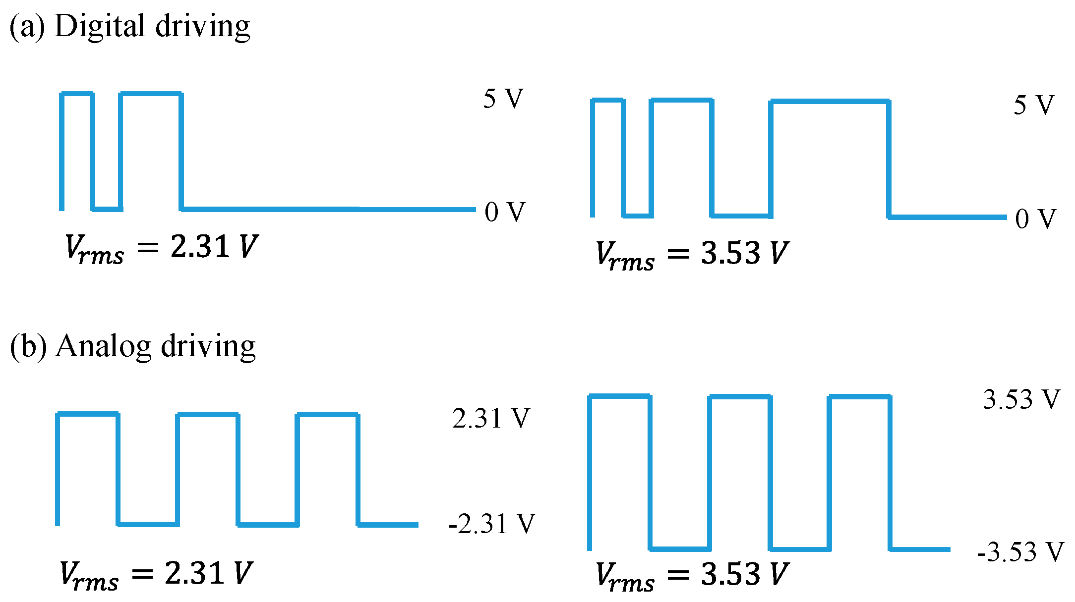
Phase stability in terms of time-fluctuation is the major weakness in PWM devises [60,61,62]. The different working principles of digital and analog driving schemes are shown in Figure 7 [63].
Vrms can be calculated between the voltages (v1 and v2) applied in a short period of time (t1 and t2), as shown in the following equation:
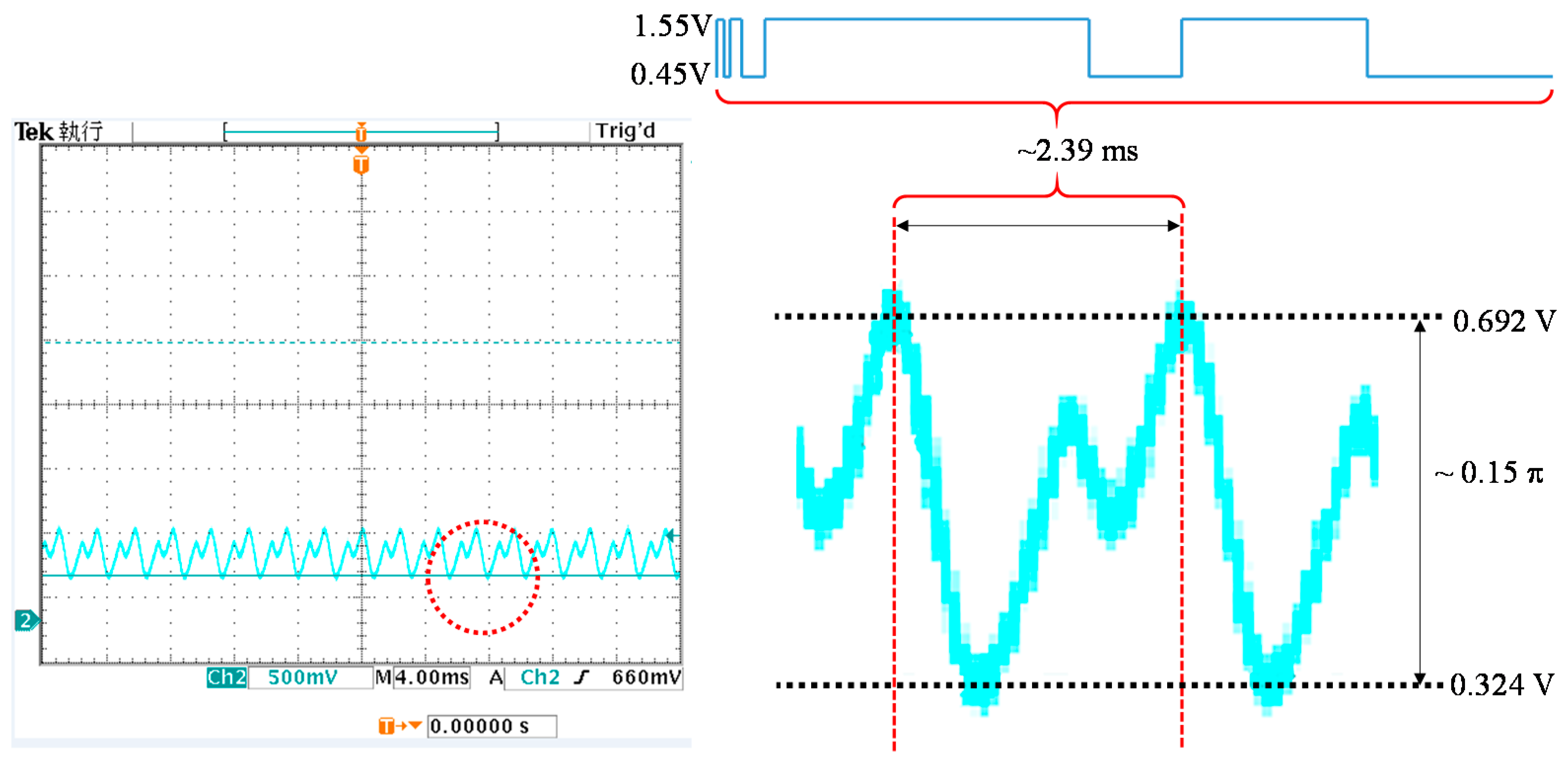
Briefly, the digital driving scheme maintains a constant voltage (ΔV) while changing the pulse width to achieve the various Vrms values. The flicker yields from charging and discharging phenomenon within the sub-millisecond because the instantaneous voltage recognized by liquid crystal is the time ratio between the pulses at constant voltage (ΔV) in the driving cycle. On the other hand, the analog driving scheme achieves its Vrms values by changing the applied voltages at constant frequency. There is no obvious flicker in the analog driving scheme because the instantaneous voltage resembling Vrms is perceived by the liquid crystals without a noticeable charging and discharging phenomenon. Figure 8 shows the phase flicker generated from digital drive at gray level 70 using a LETO panel.
Two measurements with different photodetector settings are performed to show the phase shift and phase flicker in each gray scale. The digital color light sensor (TCS-3404 from TAOS) is adopted as a photodetector for the phase linearity and phase precision measurements. The data are taken every 100 ms for each gray level, which is presented as a red line for measured phase shift in Figure 9 and Figure 10. Temporal fluctuation is measured by a polarization interferometer (PIF) with a polarizer and an analyzer aligned at 45 ° with respect to the rubbing direction. The photodetector is connected to a high-resolution oscilloscope (300 MHz 2.5 GS/s from Tektronix TDS3034B). The data are taken every few μs for each gray level. The phase flicker is determined by the maximum and minimum phase values of each gray level. The ΔV values of these three panels are 5.00V, 2.12V and 1.10V for PCM-2-01-633, PCU-3-01-633, and LETO, respectively. Their LC response times are 3.8, 2.8, and 20.7 ms, and their resulting mean standard deviations (mSTD) are 0.14 π, 0.12 π, and 0.04 π, respectively. The small ΔV setting in the digital driving scheme is able to minimize the flicker, as suggested in the data. To validate the assumption, the thicker cell gap of PCU-3-01-633 LCoS-SLM filled with the same LC was prepared to achieve 2π radius phase shift at lower ΔV = 1.04 V. The mSTD of the thicker LCoS-SLM (named PCU-3-01-633-2) is only 0.04 π. The response time, regrettably, slows considerably from 2.8 to 9.6 ms. To summarize the phase stability in the digital drive LCoS-SLM, it is able to minimize the flicker when smaller ΔV is applied for 2 π radius phase shift modulation. The slower LC response, however, is inevitable with this approach.
7. Phase Accuracy
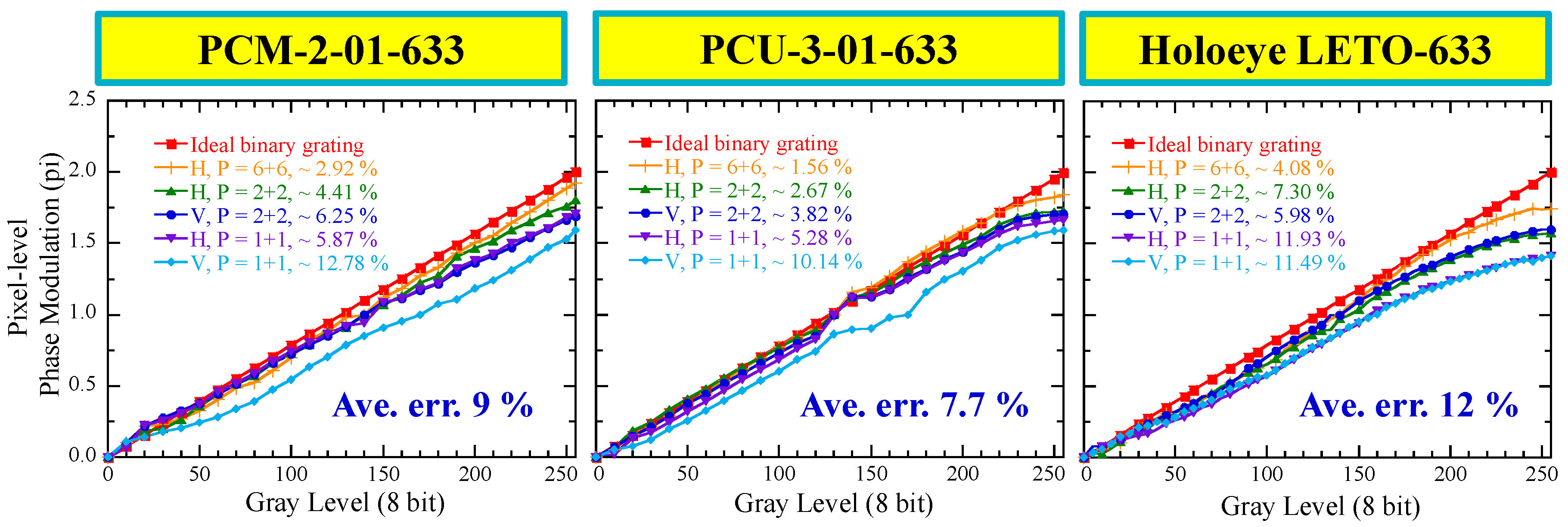
Phase accuracy is determined by the projected image. The pixel-level spatially anamorphic phenomenon provides a way to appraise the phase accuracy from a linear phase calibrated panel [64,65,66,67]. The phase error is quantified by employing various spatial frequencies and grating directions deviating from an ideal crenel-like binary grating. The deviation from the ideal binary grating is related to the non-desired LC fringing field and reverse-tilt effects [67]. To measure phase modulation, a 0th gray level (GL-0) is defined as 100% of the intensity of the light reflected from the panel. The ±1st-order light intensity is determined by the spatial frequency and orientation of the binary grating. The binary-grating differences are created by changing the corresponding gray-level pairs, in which the gray level of the reference pixel is fixed as GL-0 and changed 5–255 gray levels (GL-5-255) in the counterpart. The PCM-2-01-633, PCU-3-01-633, and LETO LCoS-SLM panels, possessing the same backplane design, are compared regarding their pixel-level spatially anamorphic phenomenon at λ = 633 nm. In Figure 11, H and V represented horizontal and vertical grating, and P is the binary grating pairs at different periods: 1 + 1, 2 + 2, and 6 + 6 pixels/grating, which correspond to spatial frequencies of 76.8, 38.4, and 12.8 lines/mm, respectively. The average error of the pixel-level phase accuracy of the horizontal and vertical grating is 9% for PCM-2-01-633, 7.7% for PCU-3-01-633, and 12% for LETO. This result suggests that PCU-3-01-633 with a small cell gap can effectively suppress the pixel-level phase accuracy error. However, the 1 + 1 in vertical grating still has 10% error. Small average phase-accuracy errors in both horizontal and vertical grating directions are necessary at the same time to minimize the error for the application of 2D CGH patterns.
8. Conclusions
LCoS technology has been developed for nearly four decades. However, due to its higher production cost and lower performance than DMD, the latter continues to dominating the present-day projection display market. Recently, high-resolution and fine pixel size LCoS backplanes have been produced by several vendors, and appear to offer more promising spatial light modulation than full high definition displays. Techniques for assessing various characteristics of high-resolution LCoS SLMs have been discussed in this review. The physics and modeling of LCs in parallel aligned LCoS were not discussed in detail due to the limited length and scope of this paper. The physics and electro-optical effects of tilted LCs, and addressed digital driving in the parallel aligned LCoS, have been thoroughly discussed by Francés et al. and Martínez, et al. [68,69,70]. During the course of developing high quality SLM panels, the phase precision, phase stability, and output phase accuracy need to be meticulously adjusted on a linearly calibrated phase panel. The novel high-quality and well-calibrated panels can generate phase-only holography and project faithful CGH design, which can be useful for 2D/3D holographic video projectors and optical telecommunications. The high phase precision, fast response time, good phase stability, and high phase accuracy of LCoS panels opens more possibilities for various applications, as discussed above. Though the benefits of LCoS panels are many, endeavors should be made to offer them at a competitive price to the public in the near future.
Author Contributions
Conceptualization: H.-M.P.C. and J.-P.Y.; writing—original draft preparation, J.-P.Y. and H.-M.P.C.; writing—review and editing, H.-M.P.C. and S.-T.W.; experimental work, J.-P.Y., H.-T.Y., Z.-N.H. and Y.H.; supervision, H.-M.P.C. and S.-T.W.
Funding
The financial support is provided by the Ministry of Science and Technology of the Republic of China under Grant Nos. 105-2622-E-009-012-CC2, 105-2221-E-009-090, and MOST 106-2221-E-009-111; and is partially supported by the Research Team of Photonic Technologies and Intelligent Systems at NCTU within the framework of the Higher Education Sprout Project by the Ministry of Education (MOE) in Taiwan.
Acknowledgments
The authors are grateful for the LCoS photos listed in Figure 1 provided by Jasper Display.
References
- Margerum, J.D.; Nimoy, J.; Wong, S.-Y. Reversible ultraviolet imaging with liquid crystals. Appl. Phys. Lett. 1970, 17, 51–53. [Google Scholar] [CrossRef]
- Beard, T.D.; Bleha, W.P.; Wong, S.-Y. Ac liquid-crystal light valve. Appl. Phys. Lett. 1973, 22, 90–92. [Google Scholar] [CrossRef]
- Ernstoff, M.N.; Leupp, A.M.; Little, M.J.; Peterson, H.T. Liquid crystal pictorial display. Int. Electron. Devices Meet. 1973, 548–551. [Google Scholar] [CrossRef]
- Efron, U.; Braatz, P.O.; Little, M.J.; Schwartz, R.N.; Grinberg, J. Silicon liquid crystal light valves: Status and issues. Opt. Eng. 1983, 22, 682–686. [Google Scholar] [CrossRef]
- Efron, U.; Wu, S.T.; Bates, T.D. Nematic liquid crystals for spatial light modulators: Recent studies. J. Opt. Soc. Am. B. 1986, 3, 247–252. [Google Scholar] [CrossRef]
- Johnson, K.M.; McKnight, D.J.; Underwood, I. Smart Spatial Light Modulators Using Liquid Crystals on Silicon. IEEE J. Quantum Electron. 1993, 29, 699–714. [Google Scholar] [CrossRef]
- Vettese, D. Liquid crystal on silicon. Nat. Photonics 2010, 4, 752–754. [Google Scholar] [CrossRef]
- Maimone, A.; Georgiou, A.; Kollin, J.S. Holographic Near-Eye Displays for Virtual and Augmented Reality. ACM Trans. Graph. 2017, 36, 85. [Google Scholar] [CrossRef]
- Matsuda, N.; Fix, A.; Lanman, D. Focal Surface Displays. ACM Trans. Graph. 2017, 36, 86. [Google Scholar] [CrossRef]
- Lazarev, G.; Gädekea, F.; Luberek, J. Ultrahigh-resolution phase-only LCOS spatial light modulator. In Proceedings of the Emerging Liquid Crystal Technologies XII, San Francisco, CA, USA, 28 January–2 February 2017. [Google Scholar]
- Inoue, T.; Tanaka, H.; Fukuchi, N.; Takumi, M.; Matsumotoa, N.; Hara, T.; Yoshida, N.; Igasaki, Y.; Kobayashi, Y. LCOS spatial light modulator controlled by 12-bit signals for optical phase-only modulation. In Proceedings of the Emerging Liquid Crystal Technologies II, San Jose, CA, USA, 9 February 2007. [Google Scholar]
- Linnenberger, A. Advanced SLMs for Microscopy. Proc. SPIE 2018, 10502, 1050204. [Google Scholar]
- Santec. Available online: http://www.santec.com/en/products/components/slm (accessed on 29 October 2018).
- Wang, M.; Zong, L.; Mao, L.; Marquez, A.; Ye, Y.; Zhao, H.; Vaquero, F.J. LCoS SLM Study and Its Application in Wavelength Selective Switch. Photonics 2017, 4, 22. [Google Scholar] [CrossRef]
- Vizsnyiczai, G.; Kelemen, L.; Ormos, P. Holographic multi-focus 3D two-photon polymerization with real-time calculated holograms. Opt. Express 2014, 22, 24217–24223. [Google Scholar] [CrossRef] [PubMed]
- Beck, R.J.; Parry, J.P.; Shephard, J.D.; Hand, D.P. Compensation for time fluctuations of phase modulation in a liquid-crystal-on-silicon display by process synchronization in laser materials processing. Appl. Opt. 2011, 50, 2899–2905. [Google Scholar] [CrossRef] [PubMed]
- Toyoda, H.; Inoue, T.; Mukozaka, N.; Hara, T.; Wu, M.H. Advances in Application of Liquid Crystal on Silicon Spatial Light Modulator (LCOS-SLM). SID Int. Symp. Dig. Tech. 2014, 45, 559–562. [Google Scholar] [CrossRef]
- Vieri, C.; Lee, G.; Balram, N.; Jung, S.H.; Yang, J.Y.; Yoon, S.Y.; Kang, I.B. An 18 megapixel 4.3” 1443 ppi 120 Hz OLED display for wide field of view high acuity head mounted displays. J. Soc. Inf. Disp. 2018, 26, 314–324. [Google Scholar] [CrossRef]
- Lee, H.S.; Jang, S.; Jeon, H.; Choi, B.S.; Cho, S.H.; Kim, W.T.; Song, K.; Chu, H.Y.; Kim, S.; Jo, S.C.; et al. Large-area Ultra-high Density 5.36” 10Kx6K 2250 ppi Display. Proc. SID Symp. Dig. Tech. 2018, 49, 607–609. [Google Scholar] [CrossRef]
- Wakunami, K.; Hsieh, P.Y.; Oi, R.; Senoh, T.; Sasaki, H.; Ichihashi, Y.; Okui, M.; Huang, Y.P.; Yamamoto, K. Projection-type see-through holographic three-dimensional display. Nat. Commun. 2016, 7, 12954. [Google Scholar] [CrossRef] [PubMed] [Green Version]
- Kim, Y.H.; Hwang, C.Y.; Choi, J.H.; Pi, J.E.; Yang, J.H.; Cho, S.M.; Cheon, S.H.; Kim, G.H.; Choi, K.; Kim, H.O.; et al. Development of high-resolution active matrix spatial light modulator. Opt. Eng. 2018, 57, 061606. [Google Scholar] [CrossRef]
- Holoeye. Available online: https://holoeye.com/spatial-light-modulators/gaea-4k-phase-only-spatial-light-modulator/ (accessed on 29 October 2018).
- Yang, J.P.; Chen, H.M.P.; Huang, Y.; Wu, S.T.; Hsu, C.; Ting, L.; Hsu, R. Sub-KHz 4000-PPI LCoS Phase Modulator for Holographic Displays. Proc. SID Symp. Dig. Tech. 2018, 49, 772–775. [Google Scholar] [CrossRef]
- Abeeluck, A.K.; Iverson, A.; Goetz, H.; Passon, E. High-Performance Displays for Wearable and HUD Applications. Proc. SID Symp. Dig. Tech. 2018, 49, 768–771. [Google Scholar] [CrossRef]
- Zeng, Z.; Zheng, H.; Yu, Y.; Asund, A.K.; Valyukh, S. Full-color holographic display with increased-viewing-angle. Appl. Opt. 2017, 56, F112–F120. [Google Scholar] [CrossRef] [PubMed]
- Yang, J.P.; Chen, H.M.P. A 3-msec Response-Time Full-Phase-Modulation 1080p LCoS-SLM for Dynamic 3D Holographic Displays. Proc. SID Symp. Dig. Tech. 2017, 48, 1073–1076. [Google Scholar] [CrossRef]
- Inoue, T.; Takaki, Y. Table screen 360-degree holographic display using circular viewing-zone scanning. Opt. Express 2015, 23, 6533–6542. [Google Scholar] [CrossRef] [PubMed]
- Ko, S.B.; Park, J.H. Speckle reduction using angular spectrum interleaving for triangular mesh based computer generated hologram. Opt. Express 2017, 25, 29788–29797. [Google Scholar] [CrossRef] [PubMed]
- Fourth Dimension Displays. Available online: https://www.forthdd.com/products/spatial-light-modulators/ (accessed on 29 October 2018).
- Lin, C.W.; Chen, H.M.P. Defect-free half-V-mode ferroelectric liquid-crystal device. J. Soc. Inf. Disp. 2010, 18, 976–980. [Google Scholar] [CrossRef]
- Turtaev, S.; Leite, I.T.; Mitchell, K.J.; Padgett, M.J.; Phillips, D.B.; Čižmár, T. Comparison of nematic liquid-crystal and DMD based spatial light modulation in complex photonics. Opt. Express 2017, 25, 29874–29884. [Google Scholar] [CrossRef] [PubMed]
- Xianyu, H.; Wu, S.T.; Lin, C.L. Dual frequency liquid crystals: A review. Liq. Cryst. 2009, 36, 717–726. [Google Scholar] [CrossRef]
- Peng, F.; Xu, D.; Chen, H.; Wu, S.T. Low voltage polymer network liquid crystal for infrared spatial light modulators. Opt. Express 2015, 23, 2361–2368. [Google Scholar] [CrossRef] [PubMed]
- Sun, J.; Chen, Y.; Wu, S.T. Submillisecond-response and scattering-free infrared liquid crystal phase modulators. Opt. Express 2012, 20, 20124–20129. [Google Scholar] [CrossRef] [PubMed]
- Peng, F.; Lee, Y.H.; Luo, Z.; Wu, S.T. Low voltage blue phase liquid crystal for spatial light modulators. Opt. Lett. 2015, 40, 5097–5100. [Google Scholar] [CrossRef] [PubMed]
- Huang, Y.; He, Z.; Wu, S.T. Fast-response liquid crystal phase modulators for augmented reality displays. Opt. Express 2017, 25, 32757–32766. [Google Scholar] [CrossRef]
- Chen, R.; Huang, Y.; Li, J.; Hu, M.; Li, J.; Wu, S.T.; An, Z. High-frame-rate liquid crystal phase modulator for augmented reality displays. Liq. Cryst. 2018. [Google Scholar] [CrossRef]
- Wu, S.T.; Efron, U. Optical properties of thin nematic liquid crystal cells. Appl. Phys. Lett. 1986, 48, 624–626. [Google Scholar] [CrossRef]
- Thalhammer, G.; Bowman, R.W.; Love, G.D.; Padgett, M.J.; Ritsch-Marte, M. Speeding up liquid crystal SLMs using overdrive with phase change reduction. Opt. Express 2013, 21, 1779–1797. [Google Scholar] [CrossRef] [PubMed]
- Lazarev, G.; Bonifer, S.; Engel, P.; Höhne, D.; Notni, G. High-resolution LCOS microdisplay with sub-kHz frame rate for high performance, high precision 3D sensor. Proc. SPIE Dig. Opt. Technol. 2017, 10335. [Google Scholar] [CrossRef]
- Meadowlark Optics. Available online: https://www.meadowlark.com/1920-1152-spatial-light-modulator-p-119?mid=18#.W34yX84zYdU (accessed on 29 October 2018).
- Xiao, K.D.; Fu, C.Y.; Dimosthenis, K.; Wuerger, S. Visual gamma correction for LCD displays. Displays 2011, 32, 17–23. [Google Scholar] [CrossRef]
- Yang, L.; Xia, J.; Chang, C.; Zhang, X.; Yang, Z.; Chen, J. Nonlinear dynamic phase response calibration by digital holographic microscopy. Appl. Opt. 2015, 54, 7799–7806. [Google Scholar] [CrossRef] [PubMed]
- Strauß, J.; Häfner, T.; Dobler, M.; Heberle, J.; Schmidt, M. Evaluation and calibration of LCoS SLM for direct laser structuring with tailored intensity distributions. Phys. Procedia 2016, 83, 1160–1169. [Google Scholar] [CrossRef]
- Zhang, H.; Zhou, H.; Li, J.; Qiao, Y.J.; Si, J.; Gao, W. Compensation of phase nonlinearity of liquid crystal spatial light modulator for high-resolution wavefront correction. J. Eur. Opt. Soc.-Rapid 2015, 10, 15036. [Google Scholar] [CrossRef]
- Engström, D.; Persson, M.; Bengtsson, J.; Goksör, M. Calibration of spatial light modulators suffering from spatially varying phase response. Opt. Express 2013, 21, 16086–16103. [Google Scholar] [CrossRef] [PubMed]
- Reichelt, S. Spatially resolved phase-response calibration of liquid-crystal-based spatial light modulators. Appl. Opt. 2013, 52, 2610–2618. [Google Scholar] [CrossRef] [PubMed]
- Otón, J.; Ambs, P.; Millán, M.S.; Cabré1, E.P. Multipoint phase calibration for improved compensation of inherent wavefront distortion in parallel aligned liquid crystal on silicon displays. Appl. Opt. 2007, 46, 5667–5679. [Google Scholar] [CrossRef] [PubMed]
- Otón, J.; Ambs, P.; Millán, M.S.; Cabré1, E.P. Dynamic calibration for improving the speed of a parallel-aligned liquid-crystal-on-silicon display. Appl. Opt. 2009, 48, 4616–4624. [Google Scholar] [CrossRef] [PubMed]
- Lu, Q.; Sheng, L.; Zeng, F.; Gao, S.; Qiao, Y. Improved method to fully compensate the spatial phase nonuniformity of LCoS devices with a Fizeau interferometer. Appl. Opt. 2016, 55, 7796–7802. [Google Scholar] [CrossRef] [PubMed]
- Xia, J.; Chang, C.; Chen, Z.; Zhu, Z.; Zeng, T.; Liang, P.Y.; Ding, J. Pixel-addressable phase calibration of spatial light modulators: A common-path phase-shifting interferometric microscopy approach. J. Opt. 2017, 19, 125701. [Google Scholar] [CrossRef]
- Gelder, R.V.; Melnik, G. Uniformity metrology in ultra-thin LCoS LCDs. J. Soc. Inf. Disp. 2006, 14, 233–239. [Google Scholar] [CrossRef]
- Zhang, Z.; Chapman, A.M.J.; Collings, N.; Pivnenko, M.; Moore, J.; Crossland, B.; Chu, D.P.; Milne, B. High Quality Assembly of Phase-Only Liquid Crystal on Silicon (LCOS) Devices. J. Disp. Technol. 2011, 7, 120–126. [Google Scholar] [CrossRef]
- Zhang, Z.; Yang, H.; Robertson, B.; Redmond, M.; Pivnenko, M.; Collings, N.; Crossland, W.A.; Chu, D.P. Diffraction based phase compensation method for phase-only liquid crystal on silicon devices in operation. Appl. Opt. 2012, 51, 3837–3846. [Google Scholar] [CrossRef] [PubMed]
- Zhang, Z.; Pivnenko, M.; Salazar, I.M.; You, Z.; Chu, D.P. Advanced die-level assembly techniques and quality analysis for phase-only liquid crystal on silicon devices. Proc IMechE Part B J Eng. Manuf. 2016, 230, 1659–1664. [Google Scholar] [CrossRef]
- Čižmár, T.; Mazilu, M.; Dholakia, K. In situ wavefront correction and its application to micromanipulation. Nat. Photonics 2010, 4, 388–394. [Google Scholar] [CrossRef]
- Serati, S.; Xia, X.; Mughal, O.; Linnenberger, A. High-resolution phase-only spatial light modulators with submillisecond response. In Proceedings of the Optical Pattern Recognition XIV, Orlando, FL, USA, 6 August 2003. [Google Scholar]
- Harriman, J.; Linnenberger, A.; Serati, S. Improving spatial light modulator performance through phase compensation. In Proceedings of the Advanced Wavefront Control: Methods, Devices, and Applications II, Denver, CO, USA, 12 October 2004. [Google Scholar]
- Xu, J.; Qin, S.; Liu, C.; Fu, S.; Liu, D. Precise calibration of spatial phase response nonuniformity arising in liquid crystal on silicon. Opt. Lett. 2018, 43, 2993–2996. [Google Scholar] [CrossRef] [PubMed]
- Collings, N.; Christmas, J.L. Real-Time Phase-Only Spatial Light Modulators for 2D Holographic Display. J. Disp. Technol. 2015, 11, 278–284. [Google Scholar] [CrossRef]
- Lizana, A.; Márquez, A.; Lobato, L.; Rodange, Y.; Moreno, I.; Iemmi, C.; Campos, J. The minimum Euclidean distance principle applied to improve the modulation diffraction efficiency in digitally controlled spatial light modulators. Opt. Express 2010, 18, 10581–10593. [Google Scholar] [CrossRef] [PubMed]
- Márquez, J.G.; López, V.; Vega, A.G.; Noé1, E. Flicker minimization in an LCoS spatial light modulator. Opt. Express 2012, 20, 8431–8441. [Google Scholar] [CrossRef] [PubMed]
- Moore, J.R.; Collings, N.; Crossland, W.A.; Davey, A.B.; Evans, M.; Jeziorska, A.M.; Komarˇcevic´, M.; Parker, R.J.; Wilkinson, T.D.; Xu, H. The Silicon Backplane Design for an LCOS Polarization-Insensitive Phase Hologram SLM. IEEE Photonics Technol. Lett. 2008, 20, 60–62. [Google Scholar] [CrossRef]
- Bouvier, M.; Scharf, T. Analysis of nematic-liquid-crystal binary gratings with high spatial frequency. Opt. Eng. 2000, 39, 2129–2137. [Google Scholar] [CrossRef]
- Márquez, A.; Iemmi, C.; Moreno, I.; Campos, J.; Yzuel, M.J. Anamorphic and spatial frequency dependent phase modulation on liquid crystal displays. Optimization of the modulation diffraction efficiency. Opt. Express 2005, 13, 2111–2119. [Google Scholar] [CrossRef] [PubMed] [Green Version]
- Cuypers, D.; Smet, H.D.; Calster, A.V. Electronic Compensation for Fringe-Field Effects in VAN LCOS Microdisplays. SID Symp. Dig. Tech. 2008, Papers 39, 228–231. [Google Scholar] [CrossRef]
- Lobato, L.; Lizana, A.; M´arquez, A.; Moreno, I.; Iemmi, C.; Campos, J.; Yzuel, M.J. Characterization of the anamorphic and spatial frequency dependent phenomenon in liquid crystal on silicon displays. J. Eur. Opt. Soc. 2011, 6, 11012S. [Google Scholar] [CrossRef]
- Francés, J.; Márquez, A.; Martínez-Guardiola, F.J.; Bleda, S.; Gallego, S.; Neipp, C.; Pascual, I.; Beléndez, A. Simplified physical modeling of parallel-aligned liquid crystal devices at highly non-linear tilt angle profiles. Opt. Express 2018, 26, 12723–12741. [Google Scholar] [CrossRef] [PubMed] [Green Version]
- Martínez, F.J.; Márquez, A.; Gallego, S.; Francés, J.; Pascual, I.; Beléndez, A. Effective angular and wavelength modeling of parallel aligned liquid crystal devices. Opt. Laser Eng. 2015, 74, 114–121. [Google Scholar] [CrossRef] [Green Version]
- Martínez, F.J.; Márquez, A.; Gallego, S.; Francés, J.; Ortuño, M.; Francés, J.; Beléndez, A.; Pascual, I. Electrical dependencies of optical modulation capabilities in digitally addressed parallel aligned liquid crystal on silicon devices. Opt. Eng. 2014, 53, 067104. [Google Scholar] [Green Version]
Figure 1.
Photos of (a) 2K1K and (b) 4K2K panels from Jasper Display Corp.

Figure 2.
Schematic of various applications of phase-only liquid crystal on silicon spatial light modulator (LCoS-SLM).
Figure 2.
Schematic of various applications of phase-only liquid crystal on silicon spatial light modulator (LCoS-SLM).

Figure 3.
Quantitative assessment indicators for LCoS-SLM.

Figure 4.
Pixel density and pixel pitch specifications for current LCoS-SLM integrated circuit (IC) backplanes.
Figure 4.
Pixel density and pixel pitch specifications for current LCoS-SLM integrated circuit (IC) backplanes.

Figure 5.
The scheme of eight different sessions (mxy) over the entire active area in the Equation (4).
Figure 5.
The scheme of eight different sessions (mxy) over the entire active area in the Equation (4).

Figure 6.
The phase precision measurements of 3 different LCoS-SLMs. The inserts are the enlarged figure from gray level 100 to 150. The values in a. is the phase linearity error (APAE%); and b. is the mSTD of phase precision error.
Figure 6.
The phase precision measurements of 3 different LCoS-SLMs. The inserts are the enlarged figure from gray level 100 to 150. The values in a. is the phase linearity error (APAE%); and b. is the mSTD of phase precision error.

Figure 7.
The schemes of digital and analog driving waveforms.

Figure 8.
The digital drive waveform and its corresponding phase flicker measured in the high-resolution oscilloscope.
Figure 8.
The digital drive waveform and its corresponding phase flicker measured in the high-resolution oscilloscope.

Figure 9.
The phase stability measurements of PCM-2-01-633, and LETO LCoS-SLMs at 633 nm.

Figure 10.
The phase stability measurements of PCU-3-01-633 with two different cell gap LCoS-SLMs at 633 nm.
Figure 10.
The phase stability measurements of PCU-3-01-633 with two different cell gap LCoS-SLMs at 633 nm.

Figure 11.
The phase accuracy measurements of three different LCoS-SLMs at 633 nm.


Table 1.
Four main LCoS phase modulator providers and their unique products.
| HOLOEYE Photonics AG | Hamamatsu Photonic | Meadowlark Optics | Santec Corp. |
|---|---|---|---|
| Products | Products | Products | Products |
| 1. PLUTO-2: VIS-014, VIS-016, VIS-020, VIS-056 2. LETO: LETO-only 3. GAEA-2: VIS-036 | 1. X-10468: -01, -02, -03 2. X-13138:-01, -02, -03 | 1. P512: P-, PDM-, HSP-, HSPDM-, ODP-, ODPDM 2. P1920: P-, HSP- | 1. SLM-100: -01 2. SLM-200: -01 |
| Features | Features | Features | Features |
| 1. UHD 4K-Panel (7000 ppi) 2. Driver Interface Up to 600 MHz(HDMI 2.0) 3. SDK Solution | 1. Pure, Linear and Precise Phase Control 2. High-Power-Use | 1. Analogy Driving Scheme 2. Fast LC Response Time 3. Sub-KHz PCIe Interface | 1. Super Flatness Available: λ/40 2. 10-bit LUT |
| * Only List for VIS Light-Region-Use LCoS-SLM (Top. = 35 °C) * BNS LCoS-SLM is acquired by Meadowlark Optics in 2014 | |||
© 2018 by the authors. Licensee MDPI, Basel, Switzerland. This article is an open access article distributed under the terms and conditions of the Creative Commons Attribution (CC BY) license (http://creativecommons.org/licenses/by/4.0/).
Share and Cite
MDPI and ACS Style
Chen, H.-M.P.; Yang, J.-P.; Yen, H.-T.; Hsu, Z.-N.; Huang, Y.; Wu, S.-T. Pursuing High Quality Phase-Only Liquid Crystal on Silicon (LCoS) Devices. Appl. Sci. 2018, 8, 2323. https://0-doi-org.brum.beds.ac.uk/10.3390/app8112323
AMA Style
Chen H-MP, Yang J-P, Yen H-T, Hsu Z-N, Huang Y, Wu S-T. Pursuing High Quality Phase-Only Liquid Crystal on Silicon (LCoS) Devices. Applied Sciences. 2018; 8(11):2323. https://0-doi-org.brum.beds.ac.uk/10.3390/app8112323
Chicago/Turabian StyleChen, Huang-Ming Philip, Jhou-Pu Yang, Hao-Ting Yen, Zheng-Ning Hsu, Yuge Huang, and Shin-Tson Wu. 2018. "Pursuing High Quality Phase-Only Liquid Crystal on Silicon (LCoS) Devices" Applied Sciences 8, no. 11: 2323. https://0-doi-org.brum.beds.ac.uk/10.3390/app8112323
Note that from the first issue of 2016, this journal uses article numbers instead of page numbers. See further details here.