Control Requirements for Future Gas Turbine-Powered Unmanned Drones: JetQuads


Centre for Propulsion Engineering, School of Aerospace Transport and Manufacturing (SATM), Cranfield University, Cranfield MK43 0AL, UK
*
Author to whom correspondence should be addressed.
Appl. Sci. 2018, 8(12), 2675; https://0-doi-org.brum.beds.ac.uk/10.3390/app8122675
Submission received: 28 September 2018
/
Revised: 14 December 2018
/
Accepted: 15 December 2018
/
Published: 19 December 2018
(This article belongs to the Special Issue Gas Turbine Engine - towards the Future of Power)
Abstract
:The next generation of aerial robots will be utilized extensively in real-world applications for different purposes: Delivery, entertainment, inspection, health and safety, photography, search and rescue operations, fire detection, and use in hazardous and unreachable environments. Thus, dynamic modeling and control of drones will play a vital role in the growth phase of this cutting-edge technology. This paper presents a systematic approach for control mode identification of JetQuads (gas turbine-powered quads) that should be satisfied simultaneously to achieve a safe and optimal operation of the JetQuad. Using bond graphs as a powerful mechatronic tool, a modular model of a JetQuad including the gas turbine, electric starter, and the main body was developed and validated against publicly available data. Two practical scenarios for thrust variation as a function of time were defined to investigate the compatibility and robustness of the JetQuad. The simulation results of these scenarios confirmed the necessity of designing a compatibility control loop, a stability control loop, and physical limitation control loops for the safe and errorless operation of the system. A control structure with its associated control algorithm is also proposed to deal with future challenges in JetQuad control problems.
1. Introduction
Having recently reached the commercial mainstream, drones will be utilized in different aspects of human beings’ lifestyles in the future. New advanced delivery systems designed and being used to safely get packages to customers in 30 min or less using unmanned aerial vehicles have a great potential to enhance the services provided to millions of customers in the future. This system also will increase the overall safety and efficiency of the transportation system [1]. There is also wide interest in flying robots in the toy industry. The different types of quadrotors and toy drones will help children to be creative, excited, and familiarize themselves with this cutting-edge technology [2]. The use of unmanned aerial vehicles (UAVs) for capturing visual information in areas that are hard to reach or dangerous for humans is another interesting application of drones [3]. This application would bring a huge advantage in terms of time saving, cost, and human risk when it is necessary to inspect areas that are either dangerous or difficult to reach for humans, such as power lines, power plant boilers, bridges, tunnels, hydraulic dam walls, and pipelines [4,5]. The potential impacts of future aerial robots on other applications such as aerial photography and firefighting are also clear [6,7].
In the last two decades, quadcopters (also called quadrotor helicopters or quadrotors) have been considered to be the most practical form of aerial robots [8]. The modeling and simulation [9], control and stabilization [10,11], and dynamic behavior prediction [12] of these aerial robots have been widely studied and investigated in the literature. Thus, different aspects of performance prediction and optimization of these robots are completely understood. The main conclusion of the literature has been that for aerial robots to become a standard tool in everyday use, it is vital that they can be operated efficiently by a non-expert pilot and that the navigation system be robust enough to remain operational in rough, industrial conditions. Consequently, the most important challenge for the development phase of this technology is the control system. In other words, having an accurate and precise control strategy is a “must” for safe and efficient operation of all types of aerial robots. In order to design a reliable control structure, a dynamic model (a control-oriented model (COM)) is needed to simulate the behavior of the drone in different working conditions. This model should be reliable, precise, and accurate to enable control experts to develop an effective control strategy for this mechatronic product. This model should also be fast enough to be used in iterative procedures of control system design.
In 2016, a new type of aerial robots was introduced and patented: JetQuads (JQs). The JetQuad is a quadrotor in which the propellers are replaced with jet engines [13]. Thus, it is a jet engine-powered drone that could have a revolutionary impact in the next generation of aerial robots. The main advantage of using jet engines in drones is that the turbines can run on ordinary diesel fuel. As a result, the drone is mechanically simple and very powerful. The JetQuad outperforms conventional electrical drones in two aspects, energy density and power-to-weight ratio:
- The energy density measures energy storage in a unit mass. The JetQuad uses diesel fuel with an energy density of 40 MJ/kg, whereas electrical drones use solid lithium-based batteries that at most have an energy density of 1 MJ/kg. Thus, for the same on-board mass of fuel (or battery) storage, the JetQuad stores 40 times more energy than the equivalent electrical drone. Although jet engines are heavier than electrical motors, they have much higher power-to-weight ratios, so this penalty is insignificant. The U.S. Department of Energy (DOE) has recently initiated a five-year research project to develop next-generation battery technology. The DOE targets an energy density achievement of 3 MJ/kg energy density. This is still 1/10 of the energy density of diesel. As a result, the JetQuad will remain competitive for many years to come [13].
- The power-to-weight ratio determines how much power a given engine outputs for a given mass of that engine. Electrical drones have a large penalty in this regard. A brushless electrical motor, on its own, has a very large power-to-weight ratio. However, when added to the weight of propeller, electronic speed controllers, and batteries, this ratio is greatly decreased. Turbine-based engines, such as jet engines, do not suffer from this problem. More specifically, the JetQuad uses microturbines that have an ultrahigh rotation rate and lead to vast amounts of power produced from a small engine. In addition, electrical drones must limit current flow to prevent the overheating of electronics that support smooth motor operation. In contrast, fuel flow rate is the limiting factor for turbine-based engines. It gives jet-engine designers the flexibility to extract much more power from smaller motors [13].
However, the dynamic behavior and control requirements for the JQ are different from those of quadrotors. This topic has not been considered in the literature yet. Thus, the main contribution of this paper is to focus on control requirements and control mode identification of the JQ to enable researchers to focus on control system designs and optimization for this promising concept.
The JQ is a quad jet engine-powered drone proposed by FusionFlight in 2016 [13]. It is based on patented air booster (AB) technology that allows for stable and high-performance flight through the atmosphere. It will push the frontiers of drone technology to a whole new level in the future. The main structure of a JQ is shown in Figure 1. It is composed of a main body and four microjet engines. Each microturbine uses an electric starter as well.
The modeling and simulation of the JQ was presented and discussed in detail in References [14,15,16]. The bond graph as a graphical representation tool for physical dynamic systems was utilized to model and simulate the dynamic behavior of the JQ.
A bond graph is a very suitable approach to modeling mechatronic systems, as it allows the conversion of the system into state-space representation [17,18,19,20,21]. The bond graph has been used in turbomachinery applications widely: Gas turbine modeling and analysis [22,23,24], noise prediction and control [25,26], and surge prediction and control [27,28,29] are topics in which a bond graph has been successfully used. In previous studies by the authors, both propulsion and the main body of the JQ were modeled in a bond graph, and these models were then combined to predict the dynamic behavior of the system [14]. This model was used for this paper to generate more results in order to develop the control requirements for the JQ as well as to identify control modes that should be satisfied simultaneously for safe and optimal operation of the JQ.
For this purpose, a brief summary of the modeling approach is first presented, and the developed model is explained in detail. Two different scenarios for thrust profile are then defined to analyze the dynamic behavior of the JQ from compatibility and robustness points of view. Based on the simulation results, the Jet Quad control requirements are identified and prioritized, and essential control modes are defined. A control structure with its associated control algorithm to satisfy all control modes simultaneously is finally proposed.
2. JetQuad Modeling
As a case study, the JQ developed by FusionFlight, “AB4 JetQuad: Quad-Turbine Drone”, is used in this paper. The characteristics of the AB4 are shown in Table 1. As mentioned earlier, the model of the JQ was developed using a bond graph in previous studies by the authors. Full details about the modeling procedure can be found in References [14,15,16]. The main assumptions used in the modeling approach are as follows:
- Heat loss in components is negligible.
- Inlet pressure drop is negligible.
- The compressor mass flow rate is constant.
- The turbine mass flow rate is constant and has no effect on energy storage.
- The nozzle mass flow rate is constant, with no effect on energy storage.
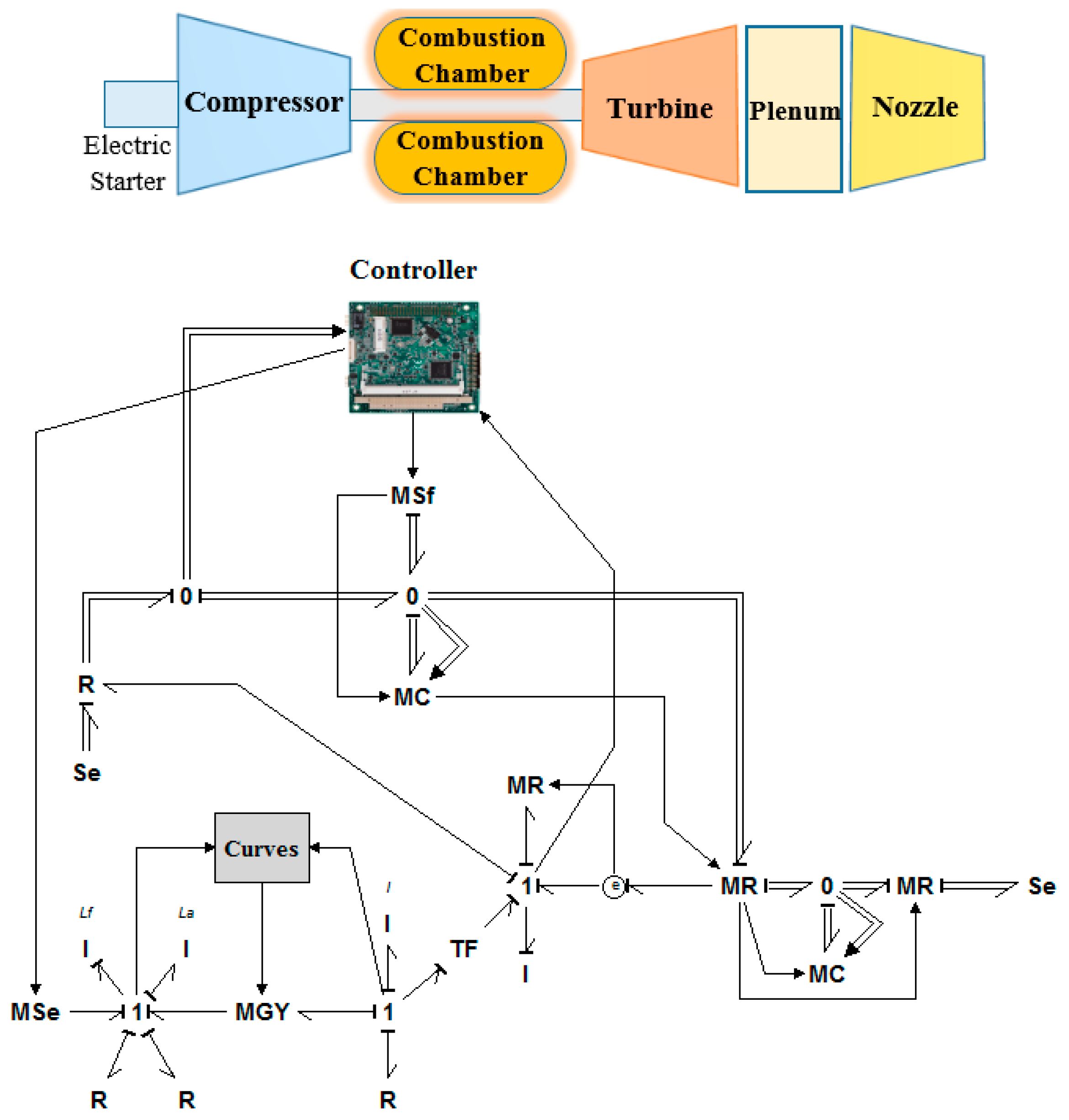
The schematic of the jet engine and the generated bond graph model are shown in Figure 2. The main parameters of the gas turbine, as well as the equations used to generate the bond graph model for jet engines, are listed in Table 2 and Table 3, respectively. The internal control system of the jet engine is an industrial min-max controller to regulate the fuel flow to the combustion chamber in order to follow the required thrust profile precisely. This controller was also discussed and simulated in detail in References [30,31,32]. This strategy is to satisfy all jet engine control modes simultaneously to protect the engine from malfunctions and physical limitations.
Figure 2 shows the complete dynamic model of the gas turbine engine after coupling the bond-graph submodels in which a one-to-one map between the components exists. This figure shows the modular modeling ability of the bond graph approach.
Here, 20-sim software was used to generate the bond graph model for the JQ: 20-sim is a modeling and simulation program for mechatronic systems in which you can enter a model graphically, similarly to drawing an engineering scheme. With these models, you can simulate and analyze the behavior of multidomain dynamic systems and create control systems. Moreover, bond graphs are a network-like description of physical systems in terms of ideal physical processes in which the system characteristics are split up into an (imaginary) set of separate elements. Each element describes an idealized physical process.
For jet engine modeling, the compressor, turbine, and nozzle are considered to be energy dissipater elements (resistance), and the combustion chamber and shaft dynamics are modeled as energy capacitor elements (i.e., capacitor and inertia). These elements are connected together by energy and information bonds, and zero and one junctions.
As can be seen in Table 3, there are two different types of equations for modeling purposes: algebraic equations and differential equations. It should be noted that combustion chamber, shaft dynamics, and plenum are modeled using differential equations, whereas compressors, turbines, and nozzle models use algebraic equations. The numerical solution starts with the differential equations to calculate inputs for algebraic equations in a predefined ambient condition, and the fuel flow is calculated by the controller. Then, the algebraic equations are solved to complete a time step and to prepare the data for the next step of differential equations. The procedure of the numerical method used for modeling purposes in this paper is shown in Figure 3.
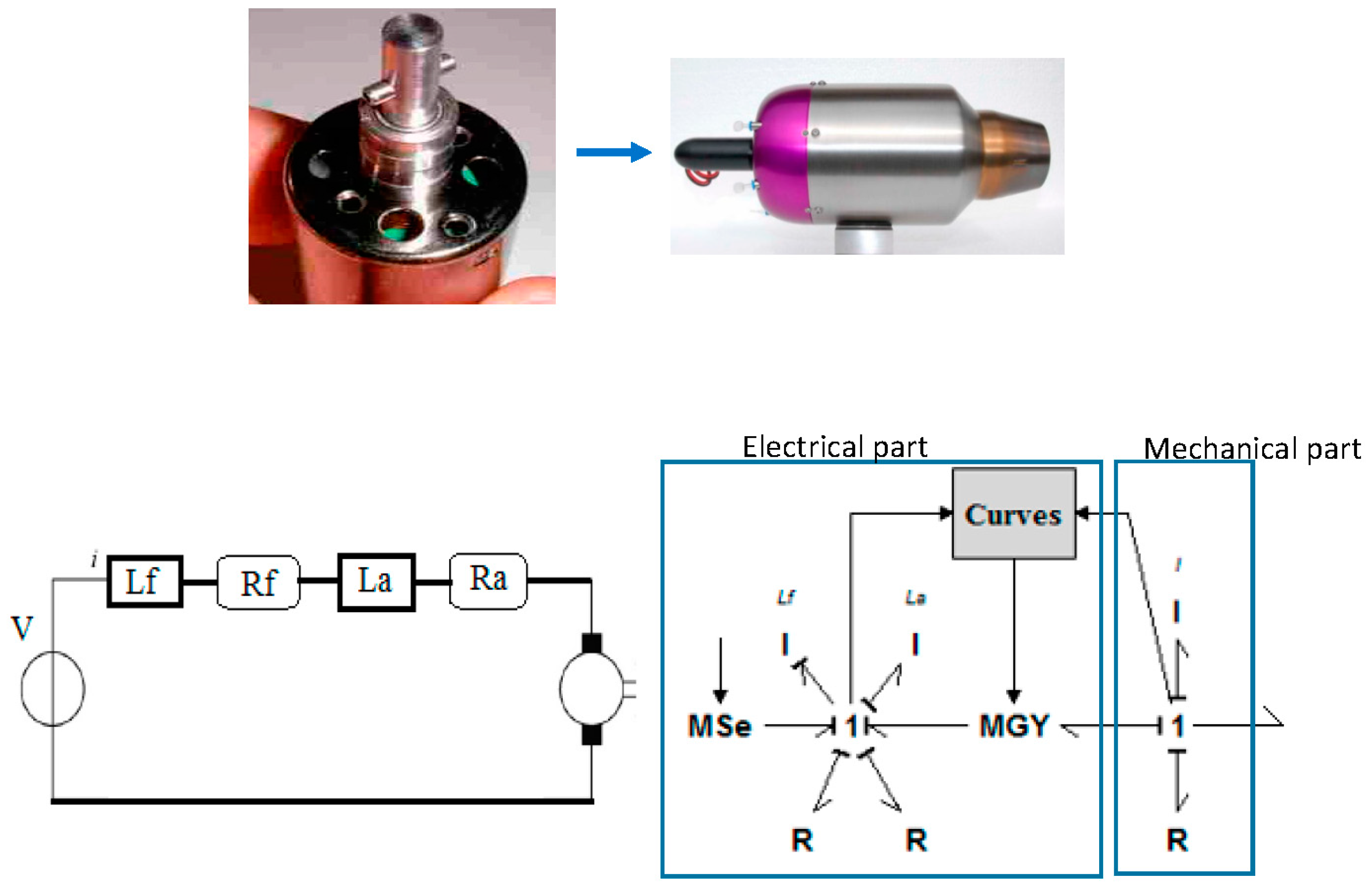
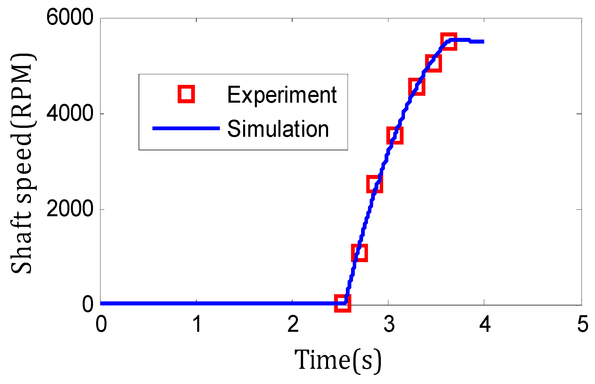
Moreover, the jet engines use a DC electric starter motor to operate. The starter motor model comprises electrical and mechanical parts. The electrical part includes stator windings and battery connections to convert the battery electrical energy to mechanical energy on the shaft. The mechanical part, which transfers the produced torque by the electrical part to the shaft, contains the shaft and the ball bearings. This device was also (both the mechanical part and electrical part) modeled in detail in References [14,15,16,21], and the results were validated against experimental data. The electric starter, its schematic, and the generated bond graph model are shown in Figure 4. The starter motor characteristics are shown in Table 4. In addition, Figure 5 confirms the validity of the model by comparing the results to experimental data.
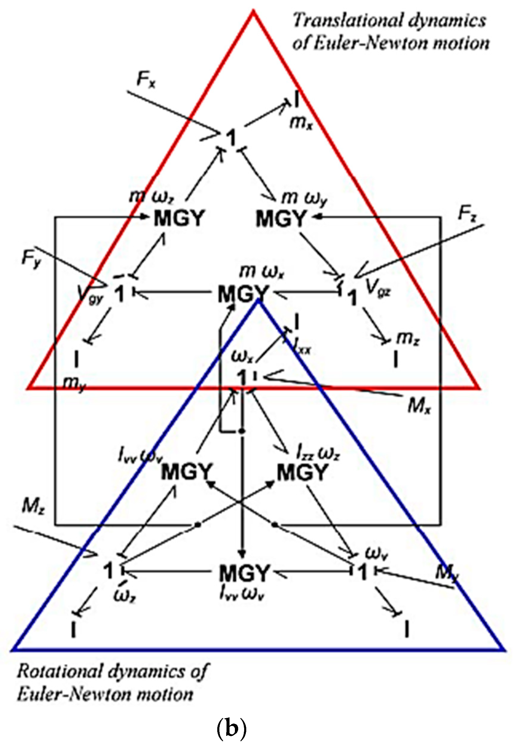
Finally, by combination of modular models of JQ components, the whole model is developed as shown in Figure 6. Figure 6a shows the jet engine model with different elements, as discussed earlier. The rigid body motion of the main body is defined by a set of Euler’s equations that are presented in Figure 6b. The combination of four jet engine models, electric starters, main body, and the controller are shown in Figure 6c. As shown in this figure, different components of the JetQuad model are combined together using zero and one junctions and by information and energy bonds. Just one of the jet engine models (on the right side of the figure) is expanded, and the three others are masked to keep the figure tidy. The engine control system is also an internal industrial min-max control strategy that regulates fuel flow into the jet engines to satisfy all engine control modes [30,31,32]. This model is able to predict the dynamic behavior of the JQ with any predefined thrust profile. Thus, different scenarios for thrust profiles could be inserted into the model to investigate the dynamics of the JQ.
3. JetQuad Simulation Results
In order to investigate the control requirements of the JQ, the generated model was then tested on two practical scenarios: (i) A compatibility test and (ii) a robustness test. For each case, a predetermined variation of thrust was specified as a function of time. The displacement, velocity, and acceleration of the whole system was simulated and discussed in each scenario to identify the requirements of the control system for the JQ.
3.1. Scenario (i): Compatibility Test
The first scenario examined the compatibility of the JQ system to manage the displacement and velocity in high and low thrust values and also in a transition between these two conditions. Figure 7 shows the prescribed variation of thrust over a duration of 150 s. This thrust profile was assumed to be the same for all four jet engines of the JQ. As can be seen from this figure, for t ≤ 70 s, the thrust value was constant at 61 N. It then decreased to the value of 51 N at t = 85 s and remained at this level for a further 15 s. Then it returned to the start value at t = 115 s and remained constant until the end of the simulation. The results of this compatibility simulation are shown in Figure 8 and Figure 9. Figure 8 shows the variation of the position of JQ in the x, y, and z directions. Figure 9a–d shows the variation in linear and angular velocities and accelerations of the JQ in different directions.
3.2. Discussion of Scenario (i) Results
As can be seen in Figure 1 (the architecture of the JQ), the inserted thrust to the JQ is in the z direction. Thus, it was expected that the displacement of the JQ to be only in the z direction and to be consistent with the thrust variation. However, Figure 8 shows that after changing the level of thrust, displacements in the y and x directions emerged and also increased after another change in the thrust profile at t = 115. This was caused by the structure of the JQ and the mutual effects between body and jet engines. This figure clearly confirms the necessity of having a controller for the whole JetQuad to set different thrust profiles for each jet engine to get a desired displacement from the JQ in different directions. Thus, the first control requirement is a compatibility control mode.
Figure 9a,b shows the variation of linear and angular velocities of the JQ in different directions. The linear velocity was related to the change of the position and is discussed in the Figure 8 results. However, the angular velocity means that there was an instability in the position of the JQ itself. In other words, angular velocity represented the rotation of the JQ around its axes, and it was not a desirable motion in a real-world application. Although the values of angular velocity and acceleration were low, it still confirmed the necessity of having a controller for a stability control mode. Figure 9c,d shows the variation of linear and angular acceleration of the JQ in different directions. Again, the variation in accelerations on the x and y axes confirmed that the stability control mode should be satisfied in the control structure design. However, with respect to the low values of angular velocity and acceleration, the stability control mode could be considered to be a lower priority than the compatibility control mode.
3.3. Scenario (ii): Robustness Test
The robustness of the JQ was then tested on its ability to react to the severe change of thrust as a function of time, as shown in Figure 10. The value of the thrust changed from a high value to lower values over 7 s. The objective of this change was to investigate the dynamic behavior of the JQ during sudden changes of the thrust, in other words to validate the robustness of the JQ in different operating conditions. The results of the robustness test simulation are shown in Figure 11, Figure 12, Figure 13 and Figure 14.
3.4. Discussion of Scenario (ii) Results
Figure 11 shows the variation of displacements of the JQ in the x, y, and z directions. As can be seen in this figure, the variation in the x and y displacements was negligible even with severe changes of thrust in a short time duration. It seems that the system performed robustly. However, the z direction displacement was very huge, and it might result in overspeed or integrity issues, as well as exceed regulations for drones. In order to investigate this matter more precisely, Figure 12, Figure 13 and Figure 14 show the variation in linear velocity and acceleration, as well as the angular velocity for the JQ. These results clearly confirmed the above conclusion. Figure 12 shows that the velocity of the JQ in the z direction increased up to 280 m/s, with a very high acceleration value (43 m/s2 from Figure 13). Thus, this confirmed the necessity of having a physical limitation control mode for the JQ to protect the system from overspeed, overacceleration, and other malfunctions. However, the velocity and acceleration values in other directions were very low and negligible. Therefore, the robustness control mode could be considered to be a lower priority than the physical limitation control mode.
4. JetQuad Control Requirements
From the above-mentioned analysis, the JQ control requirements could be summarized as follows:
- The compatibility test showed that a control loop is required to provide a compatible motion for the JQ with respect to a predefined thrust profile. The input of this control loop would be a predefined displacement (trajectory) for the JQ, and the output would be the thrust profile for each jet engine as a function of time.
- The criteria for testing the compatibility control mode would be the value of displacement, velocity, and acceleration of the JQ in different directions. For instance, if the target is a vertical movement, the value of the displacements and velocities on the x and y axes should be zero (or negligible).
- A stability control mode should also be considered for the JQ. However, with respect to the values of angular velocity and acceleration in the compatibility test, it could be considered to be a lower priority than the compatibility control mode.
- The necessity of the stability control mode depends on the application of the JQ. Thus, a control loop could be designed in this regard with a predefined angular velocity and acceleration profile as the input and the modification of the thrust profile as the output of the controller.
- The robustness test showed that the structure of the JQ was robust and performed well even with severe changes in thrust profile. Thus, the robustness control mode is not a “must” in the first version of the JQ controller.
- The robustness test also showed that there is a vital need for a physical limitation control mode to protect the JQ from overspeed and other malfunctions. The inputs of this control loop would be the maximum and minimum allowable values for the velocity and acceleration of the JQ, and the outputs of this loop should be compared to the compatibility control loop as constraints.
Taking the above-mentioned conclusions into account, the proposed control structure for the JQ is shown in Figure 15.
The proposed control algorithm would work as follows:
- First, the compatibility control loop calculates the appropriate thrust profile for each jet engine to minimize the error between the desired and actual trajectory of the JQ.
- The stability control loop then calculates the required modifications on the thrust profiles to minimize the instability parameters.
- The compatibility and stability control loops work together and have mutual effects on each other.
- The physical limitation control loops (e.g., maximum speed, maximum acceleration, and minimum speed) calculate the limitations for the thrust profile to protect the engine from malfunctions.
- The outputs of the physical limitation control loops are compared to the outputs of the compatibility control loop (modified by the stability control loop) in a selection mechanism, and an appropriate and safe thrust profile for each jet engine is generated as the final output of the controller.
- These thrust profiles satisfy all JQ control modes simultaneously (e.g., compatibility, stability, and physical limitations).
5. Conclusions
The control requirements for the JetQuad, a jet-powered aerial robot of the future, were identified and classified in this paper. The JQ model was generated using a bond graph as a powerful mechatronic tool. Two different scenarios were defined and tested on the model to investigate the compatibility and robustness of the system dynamic behavior. The results of these scenarios confirmed that the following control loops are required for the JQ:
- Compatibility control loop;
- Stability control loop;
- Physical limitation control loops.
Based on the results of the scenarios, a control structure for the JQ was designed and proposed to satisfy all control modes simultaneously. The proposed control algorithm starts with thrust profile development with respect to the desired trajectory for the JQ. These profiles are modified by the stability control mode. The modified profiles are compared to the outputs of the physical limitation control loops to protect the engine from malfunctions and to keep the integrity of the system. This structure could be considered to be the first step in the development of an advanced controller for JetQuads and other jet engine-powered drones in future studies.
Author Contributions
Conceptualization S.A.M-F, Methodology, Investigation, S.J., SAM-F and T.N.; Writing-Original Draft Preparation, S.J.; Writing-Review & Editing, T.N.
Funding
This research received no external funding
Conflicts of Interest
The authors declare no conflicts of interest.
Nomenclature
| constant pressure specific heat | |
| constant volume specific heat | |
| E | effort sensor |
| energy flow | |
| Fuel-to-air ratio | |
| GY | gyrator |
| enthalpy | |
| H | height |
| I | current of the voltage source |
| I | rotor inertia |
| La, Lf | the self-inductance coefficients of the armature and field windings |
| MGY | modulated gyrator |
| MSE | modulated source of effort |
| mass | |
| compressor torque | |
| mass flow rate | |
| rotational speed | |
| pressure | |
| R | the mechanical loss |
| Ra, Rf | the resistances of the armature and field |
| Se | source of effort |
| Temperature | |
| U | average velocity |
| V | voltage source |
| specific heat ratio | |
| Θ | nondimensional compressor inlet total temperature |
| Δ | nondimensional compressor inlet total pressure |
| efficiency | |
| Π | pressure ratio |
Subscripts
| C | compressor |
| D | downstream |
| Fric | friction |
| In | inlet |
| Is | isentropic |
| Mech | mechanical |
| Out | outlet |
| Ref | standard value (of pressure or temperature) |
| T | turbine |
| U | upstream |
References
- Prime Air. 2018. Available online: https://www.amazon.com/Amazon-Prime-Air/b?ie=UTF8&node=8037720011 (accessed on 18 December 2018).
- Best Robot Toys. 2016. Available online: http://bestrobotictoys.com/ (accessed on 18 December 2018).
- Omari, S.; Gohi, P.; Burri, M. Visual Industrial Inspection Using Aerial Robots. In Proceedings of the 2014 3rd International Conference on Applied Robotics for the Power Industry, Foz do Iguassu, Brazil, 14–16 October 2014. [Google Scholar] [CrossRef]
- Gohl, P.; Burri, M.; Omari, S.; Achtelik, M.; Siegwart, R. Towards Autonomous Mine Inspection. In Proceedings of the International Conference on Applied Robotics for the Power Industry (CARPI), Foz do Iguassu, Brazil, 14–16 October 2014. [Google Scholar]
- Nikolic, J.; Burri, M.; Rehder, J.; Leutenegger, S.; Huerzeler, C.; Siegwart, R. A UAV system for inspection of industrial facilities. In Proceedings of the IEEE Aerospace Conference, Big Sky, MT, USA, 2–9 March 2013. [Google Scholar]
- Le, P.H.; Wang, Z.; Hirai, S. Origami structure toward floating aerial robot. In Proceedings of the 2015 IEEE International Conference on Advanced Intelligent Mechatronics (AIM), Busan, Korea, 7–11 July 2015. [Google Scholar]
- Jimenez-Cano, A.E.; Martin, J.; Heredia, G.; Ollero, A.; Cano, R. Control of an aerial robot with multi-link arm for assembly tasks. In Proceedings of the 2013 IEEE International Conference on Robotics and Automation (ICRA), Karlsruhe, Germany, 6–10 May 2013. [Google Scholar]
- Hossain, M.R.; Rideout, D.G.; Krouglicof, D.N. Bond graph dynamic modeling and stabilization of a quad-rotor helicopter. In Proceedings of the 2010 Spring Simulation Multiconference, Orlando, FL, USA, 11–15 April 2010. [Google Scholar]
- Hossain, M.R.; Krouglicof, N. Multi-body dynamics modeling & control of quadrotor helicopter using bond graph. In Proceedings of the International Conference on Bond Graph Modeling and Simulation, Montreal, QC, Canada, 24–27 July 2016. [Google Scholar]
- Granda, J.J.; Montgomery, R.C. Automated Modeling and Simulation Using the Bond Graph Method for the Aerospace Industry; NASA: Washington, DC, USA, 2003.
- Mohammadi, V.; Ghaemi, S.; Kharrati, H. PSO tuned FLC for full autopilot control of quadrotor to tackle wind disturbance using bond graph approach. Appl. Soft Comput. 2018, 65, 184–195. [Google Scholar] [CrossRef]
- Chikhaoui, Z.; Gomand, J.; Malburet, F.; Pavel, M.; Barre, P. Towards an energetic modeling of rotorcraft using Bond-Graphs. In Proceedings of the AHS 69th Annual Forum, Phoenix, AR, USA, 21–23 May 2013. [Google Scholar]
- AB4 JetQuad. 2017. Available online: http://fusionflight.com/jetquad/ (accessed on 18 December 2018).
- Fashandi, S.A. l Montazeri-gh M. Modeling and simulation of JetQuad aerial robot. In Proceedings of the 2017 IEEE 4th International Conference on Knowledge-Based Engineering and Innovation (KBEI), Tehran, Iran, 22 December 2017; pp. 753–762. [Google Scholar] [CrossRef]
- Montazeri-Gh, M.; Fashandi, S.A.M. Application of Bond Graph approach in dynamic modelling of industrial gas turbine. Mech. Ind. 2017, 18, 410. [Google Scholar] [CrossRef]
- Montazeri-Gh, M.; Miran-F, S.A. Bond graph modeling of a jet engine with electric starter. Proc. Inst. Mech. Eng. Part G J. Aeros. Eng. 2018. [Google Scholar] [CrossRef]
- Paynter, H.M. ; The, M.I.T. Analysis and Design of Engineering Systems; The M.I.T. Press: Cambridge, MA, USA, 1961; ISBN 0-262-16004-8. [Google Scholar]
- Borutzky, W. Bond Graph Modelling of Engineering Systems; Springer: Berlin/Heidelberg, Germany, 2011; ISBN1 9783319474342 (online). ISBN2 9783319474342 (print). [Google Scholar]
- Montazeri-Gh, M.; Miran-F, S.A. Modeling and simulation of a two-shaft gas turbine propulsion system containing a frictional plate–type clutch. Proc. Inst. Mech. Eng. Part M J. Eng. Marit. Environ. 2018. [Google Scholar] [CrossRef]
- Montazeri-Gh, M.; Miran-F, S.A.; Abyaneh, S. Real-Time Simulation Test-bed For an Industrial Gas Turbine Engine’s Controller. Mech. Ind. 2018. [Google Scholar] [CrossRef]
- Montazeri-Gh, M.; Miran-F, S.A. Application of Bond-Graph Method in Microjet Engine Cold Start Modeling to Investigate the Idea of Injecting Compressed Air. Appl. Mech. Mater. 2015, 788–800, 890–894. [Google Scholar] [CrossRef]
- Krikelis, N.; Papadakis, F. Gas turbine modelling using pseudo-bond graphs. Int. J. Syst. Sci. 1988, 19, 537–550. [Google Scholar] [CrossRef]
- Movaghar, A.S.; Novinzadeh, A. Ideal Turbo charger Modeling and Simulation using Bond Graph Approach. In Proceedings of the ASME 2011 Turbo Expo: Turbine Technical Conference and Exposition: American Society of Mechanical Engineers, Vancouver, BC, Canada, 6–10 June 2011; pp. 871–879. [Google Scholar]
- Sanei, A.; Novinzadeh, A.; Habibi, M. Addition of momentum and kinetic energy effects in supersonic compressible flow using pseudo bond graph approach. Math. Comput. Model. Dyn. Syst. 2014, 20, 491–503. [Google Scholar] [CrossRef]
- Shoureshi, R.; Brackney, L. Applications of Active Adaptive Noise Control to Jet Engines; Technical Report; NASA: Washington, DC, USA, 1993.
- Diston, D.J. Unified Modelling of Aerospace Systems: A Bond Graph Approach; University of Glasgow: Glasgow, Scotland, 1999. [Google Scholar]
- Uddin, N.; Gravdahl, J.T. Bond graph modeling of centrifugal compression systems. Simulation 2015, 91, 998–1013. [Google Scholar] [CrossRef] [Green Version]
- Munari, E.; Morini, M.; Pinelli, M.; Spin, P.R. Experimental Investigation and Modeling of Surge in a Multistage Compressor. Energy Procedia 2017, 105, 1751–1756. [Google Scholar] [CrossRef]
- Uddin, N.; Gravdahl, J.T. Active compressor surge control system by using piston actuation: Implementation and experimental results. IFAC-PapersOnLine 2016, 49, 347–352. [Google Scholar] [CrossRef]
- Jafari, S.; Montazeri-Gh, M. Evolutionary optimization for gain tuning of jet engine min-max fuel controller. J. Propul. Power 2011, 27, 1015–1023. [Google Scholar] [CrossRef]
- Montazeri-Gh, M.; Fashandi, S.A.M.; Jafari, S. Theoretical and Experimental Study of a Micro Jet Engine Start-Up Behaviour. Tehnički Vjesnik 2018, 25, 839–845. [Google Scholar] [CrossRef]
- Montazeri-Gh, M.; Jafari, S.; Ilkhani, M.R. Application of particle swarm optimization in gas turbine engine fuel controller gain tuning. Eng. Optim. 2012, 44, 225–240. [Google Scholar] [CrossRef]
Figure 1.
Main structure of a JetQuad (JQ) [13].
Figure 1.
Main structure of a JetQuad (JQ) [13].

Figure 2.
Schematic of the JetQuad jet engines and the developed bond graph model.

Figure 3.
Numerical solution procedure for the modeling of jet engines.

Figure 4.
Electric starter, circuit, and the bond graph model [14].
Figure 4.
Electric starter, circuit, and the bond graph model [14].

Figure 5.
Validation of the starter motor performance model [16].
Figure 5.
Validation of the starter motor performance model [16].

Figure 6.
AB4 JetQuad bond graph model: (a) Bond graph model of jet engine; (b) bond graph representation of Euler equations; (c) combined bond graph model of the JQ.
Figure 6.
AB4 JetQuad bond graph model: (a) Bond graph model of jet engine; (b) bond graph representation of Euler equations; (c) combined bond graph model of the JQ.


Figure 7.
Prescribed variations of thrust in the compatibility scenario.

Figure 8.
Variation of displacements in the compatibility scenario.

Figure 9.
(a) Variations in linear velocities, (b) angular velocities, (c) linear accelerations, and (d) angular accelerations of the JQ in the compatibility scenario.
Figure 9.
(a) Variations in linear velocities, (b) angular velocities, (c) linear accelerations, and (d) angular accelerations of the JQ in the compatibility scenario.


Figure 10.
Prescribed variations of thrust in the robustness scenario.

Figure 11.
Variation of displacements in the robustness scenario.

Figure 12.
Variations in linear velocity in the robustness scenario.

Figure 13.
Variations in linear acceleration in the robustness scenario.

Figure 14.
Variations in angular velocity in the robustness scenario.

Figure 15.
Proposed control structure for the JetQuad.


Table 1.
JetQuad specifications.
| Main Characteristics of the AB4 JetQuad | ||
|---|---|---|
| 1 | Propulsion | Four identical microturbines each generate 25 horsepower. |
| 2 | Payload | Up to 30 lb. |
| 3 | Performance | With a 30-lb payload, the drone has an endurance of 8 min. |
| 4 | Geometry | Under 2 feet in diameter and about 2 feet tall. |
Table 2.
JetQuad specifications.
| Quantity | Value |
|---|---|
| Inlet air temperature (k) | 288 |
| Inlet air pressure (bar) | 1.01325 |
| Lower heating value (LHV) (KJ·Kg−1) | 43,323 |
| Compressor exhaust temperature (k) | 379.85 |
| Compressor isentropic efficiency | 0.76 |
| Turbine isentropic efficiency | 0.80 |
| Compressor pressure ratio | 3.78 |
| Turbine inlet gas temperature (k) | 1158.5 |
| Turbine pressure ratio | 2.024 |
| Turbine exhaust gas temperature (k) | 1015.9 |
| Combustion efficiency | 0.68 |
| Mechanical shaft efficiency | 0.99 |
Table 3.
Equations used to generate the bond graph model for the jet engine.
| Component | Equations |
|---|---|
| Compressor equations | |
| Combustion chamber model equations | |
| Turbine model equations | |
| Plenum model equations | |
| Nozzle equations | |
| Shaft model |
Table 4.
Characteristics of a DC starter motor.
| Quantity | Value |
|---|---|
| Power | 60 W |
| Efficiency | 67.6 |
| Laf | 0.002 H |
| Torque | 0.0955 N·m |
| V | 12 V |
| Ra | 0.3 ohm |
| La | 0.0005 H |
| Rf | 0.1 ohm |
| Lf | 0.001 H |
| J | 0.000015 kg·m2 |
| B | 0.00001 kg·m·s |
| I | 6.9 A |
| Nominal speed | 6000 rpm |
© 2018 by the authors. Licensee MDPI, Basel, Switzerland. This article is an open access article distributed under the terms and conditions of the Creative Commons Attribution (CC BY) license (http://creativecommons.org/licenses/by/4.0/).
Share and Cite
MDPI and ACS Style
Jafari, S.; Miran Fashandi, S.A.; Nikolaidis, T. Control Requirements for Future Gas Turbine-Powered Unmanned Drones: JetQuads. Appl. Sci. 2018, 8, 2675. https://0-doi-org.brum.beds.ac.uk/10.3390/app8122675
AMA Style
Jafari S, Miran Fashandi SA, Nikolaidis T. Control Requirements for Future Gas Turbine-Powered Unmanned Drones: JetQuads. Applied Sciences. 2018; 8(12):2675. https://0-doi-org.brum.beds.ac.uk/10.3390/app8122675
Chicago/Turabian StyleJafari, Soheil, Seyed Alireza Miran Fashandi, and Theoklis Nikolaidis. 2018. "Control Requirements for Future Gas Turbine-Powered Unmanned Drones: JetQuads" Applied Sciences 8, no. 12: 2675. https://0-doi-org.brum.beds.ac.uk/10.3390/app8122675
Note that from the first issue of 2016, this journal uses article numbers instead of page numbers. See further details here.