Article

An Early Study on Imaging 3D Objects Hidden Behind Highly Scattering Media: a Round-Trip Optical Transmission Matrix Method

1
Research Department of Information Photonics, Xi’an Institute of Optics and Precision Mechanics, Chinese Academy of Sciences, Xi’an 710119, China
2
University of Chinese Academy of Sciences, Beijing 100049, China
*
Author to whom correspondence should be addressed.
Submission received: 13 May 2018 / Revised: 13 June 2018 / Accepted: 23 June 2018 / Published: 25 June 2018
(This article belongs to the Special Issue Holography, 3D Imaging and 3D Display)

Abstract

:
Imaging an object hidden behind a highly scattering medium is difficult since the wave has gone through a round-trip distortion: On the way in for the illumination and on the way out for the detection. Although various approaches have recently been proposed to overcome this seemingly intractable problem, they are limited to two-dimensional (2D) intensity imaging because the phase information of the object is lost. In such a case, the morphological features of the object cannot be recovered. Here, based on the round-trip optical transmission matrix of the scattering medium, we propose an imaging method to recover the complex amplitude (both the amplitude and the phase) information of the object. In this way, it is possible to achieve the three-dimensional (3D) complex amplitude imaging. To preliminarily verify the effectiveness of our method, a simple virtual complex amplitude object has been tested. The experiment results show that not only the amplitude but also the phase information of the object can be recovered directly from the distorted output optical field. Our method is effective to the thick scattering medium and does not involve scanning during the imaging process. We believe it probably has potential applications in some new fields, for example, using the scattering medium itself as an imaging sensor, instead of a barrier.

1. Introduction

When imaging an object through a scattering medium, the transmitted light is consisted by the ballistic light and the scattered light [1]. The ballistic light that carries the object information migrates through the scattering medium without deviating from the forward direction. The scattered light that has been scattered randomly in all directions loses the object information and undermines the imaging quality [2]. Most methods only use the ballistic light for imaging, and the scattered light is suppressed by employing a short time gate based on nonlinear phenomena [3,4,5,6]. However, these methods are only effective for the weak scattering medium. When imaging through a highly scattering medium, almost all the light has been scattered randomly. In order to solve this problem, some methods that use the scattered light for imaging have recently been proposed. These include computational ghost imaging [7,8], wavefront shaping [9,10], speckle correlation [11,12,13], and optical transmission matrix (TM) [14,15,16,17].
Generally speaking, imaging 3D objects that are hidden behind scattering media is a challenging work. On one hand, compared with the traditional one-way imaging through a scattering medium where the light wave has only been distorted once, imaging an object that hidden behind scattering media is more difficult since the light wave has gone through a round-trip distortion: On the way in for the illumination and on the way out for the detection. In such a case, the information of the object seemingly cannot be recovered. On the other hand, two-dimensional (2D) imaging only needs to recover the intensity (amplitude) features of the object. Three-dimensional (3D) imaging is much more difficult, as both the intensity (amplitude) and the morphological (phase) features of the object should be recovered.
Although a lot of methods have ever been proposed, they are not effective for imaging 3D objects hidden behind highly scattering media. For example, the computational ghost imaging method cannot achieve round-trip imaging through scattering media because the information of the illumination wave is lost via the on-the-way-in distortion [18]. The wavefront shaping method only can image the 2D intensity object as the phase information of the object cannot be recovered, and due to the scanning process, its imaging speed is also restricted [19]. Similarly, the speckle correlation method relies on the inherent correlations in scattered speckle patterns, which makes it only applied to thin opaque layers, as the field-of-view is inversely proportional to the scattering medium thickness [12]. Different from the above methods, the optical transmission matrix (TM) can inherently characterize the scattering medium by giving the relationship between the input optical field and the output optical field [14]. Theoretically, it has the ability to recover the information of the object without loss and achieve the 3D complex amplitude imaging. Recently, this method has shown potential in focusing [15], delivering imaging [16], controlling transmitted energy [20], multispectral control [21], and acoustically modulated light [22]. However, generally speaking, they all belong to the cases working in the transmission imaging mode where the light is only distorted once. More recently, we also show that a 2D intensity object, which is completely hidden behind a scattering medium, can be imaged directly from the distorted output optical field [23]. Nevertheless, to the best of our knowledge, using the TM method to recover the complex amplitude information of the object that is hidden behind highly scattering media has not yet been reported.
In this paper, we show in principle that based on the round-trip TM, it is possible to recover the complex amplitude information of the object that is hidden behind scattering media. The imaging method and experiment setup are introduced, and a simple virtual complex amplitude object has also been constructed to verify the effectiveness of our method. The experiment results show that not only the amplitude but also the phase information of the object can be recovered.

2. Principle

As shown in Figure 1, when a target object is hidden behind a scattering medium, an active light is used to illuminate the object. In such a case, the incident plane wave has gone through a round-trip distortion, and the optical field reflected by the object can be expressed as
R ( ξ , η ) = S ( ξ , η ) O ( ξ , η ) ,
where the ‘*’ operation indicates that the corresponding ( ξ , η ) elements are multiplied. O ( ξ , η ) is the complex amplitude of the target object, and S ( ξ , η ) is the complex field distribution of the illumination wave which is seriously distorted due to the on-the-way-in process via the scattering medium. Based on these definitions, the final output optical field can be expressed as
E ( x , y ) = ξ , η K R E ( x , y ; ξ , η ) R ( ξ , η ) .
The K R E ( x , y ; ξ , η ) is a traditional one-way TM of scattering media, which has given the relationship between the reflected optical field R ( ξ , η ) and the output optical field E ( x , y ) [15].
As long as K R E ( x , y ; ξ , η ) is measured in advance, the reflected optical field R ( ξ , η ) can be recovered from E ( x , y ) directly [16]. Nevertheless, the object O ( ξ , η ) cannot be recovered yet since S ( ξ , η ) is still unknown. To overcome this problem, specially, we construct a new TM
T O E ( x , y ; ξ , η ) = K R E ( x , y ; ξ , η ) S ( ξ , η )
as the round-trip TM of the scattering medium. It can be seen from Equation (3) that, different from the traditional one-way TM K R E ( x , y ; ξ , η ) , this new TM T O E ( x , y ; ξ , η ) has additionally recorded the complex field distribution S ( ξ , η ) of the distorted illumination wave. In this way, Equation (2) can also be expressed as
E ( x , y ) = ξ , η T O E ( x , y ; ξ , η ) O ( ξ , η ) .
Now, once the T O E ( x , y ; ξ , η ) is measured, the relationship between O ( ξ , η ) and E ( x , y ) can be given directly.
Furthermore, for the convenience of calculation, the Equation (4) is converted to the matrix form as
E ( x , y ) = T O E ( x , y ; ξ , η ) × O ( ξ , η ) ,
where the ‘ × ’ represents a multiplication operation between two matrices. In this way, the object information O ( ξ , η ) can be recovered directly from the distorted output optical field E ( x , y ) by the inverse operation:
O rec ( ξ , η ) = T O E ( x , y ; ξ , η ) 1 × E ( x , y ) ,
where T O E ( x , y ; ξ , η ) - 1 is the inverse matrix (or pseudoinverse matrix for any ( ξ , η ) / ( x , y ) segments ratio) of .

3. Experimental Study

3.1. Measure the Round-Trip TM

Before imaging the object, the round-trip TM T O E ( x , y ; ξ , η ) of the scattering medium should be measured in advance.
The experimental setup is shown in Figure 2. A He-Ne laser with a wavelength of 632.8 nm is split into two by a beam splitter (BS1). The transmitted beam is reflected off by a mirror, after being reflected at a second beam splitter (BS2), the beam is distorted via the scattering medium to illuminate the DMD, then, the beam reflected by the DMD is distorted again via the scattering medium to generate the output wave. Meanwhile, the beam reflected by BS1, with the wave front being modulated by the LCVR, is used as the reference wave. At last, the output wave and the reference wave are combined to form an interference image at the CCD. In this way, the complex field distribution (both the amplitude and the phase) of the output wave can be acquired by using the phase-shifting digital holography technology [24].
To acquire the round-trip TM, we divide the DMD into 64 × 48 segments (the size of each segment: 219 μm × 219 μm) and turn on only one segment in sequence. The sketch map of the measured T O E ( x , y ; ξ , η ) are shown in Figure 3a,b for the amplitude part and the phase part, respectively (Two-dimensional input DMD segments ( ξ , η ) and output CCD segments ( x , y ) are both stretched to one-dimensional to facilitate the computation, and only part of the DMD segments and CCD segments are shown). What we want to emphasize is that the measured T O E ( x , y ; ξ , η ) has the ability to overcome the round-trip distortion simultaneously without information loss, which is owing to the fact that it not only has played the role of the one-way TM, but has also recorded the complex field distribution of the distorted illumination wave.

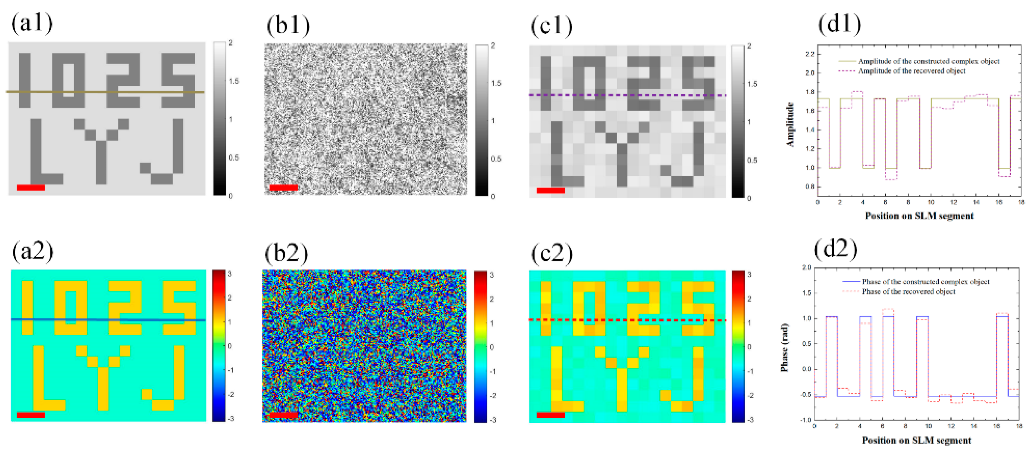
3.2. Imaging the Object

After the T O E ( x , y ; ξ , η ) is measured, the system is ready to image the target object. In order to test the imaging quality precisely, we don’t capture the image of a natural real object directly. Instead, a binary complex amplitude object which consists of the characters part and the background part, is constructed by a phase-only-modulation spatial light modulator (SLM: Meadowlark Optics, P1920-0635-HDMI, 1920 × 1152 pixels) using two phase masks O SLM ( 1 ) ( ξ , η ) and O SLM ( 2 ) ( ξ , η ) [15,16]. The mask O SLM ( 1 ) ( ξ , η ) is a plane phase whose amplitude = 1 and phase = π . The mask O SLM ( 2 ) ( ξ , η ) is obtained by flipping the phase of O SLM ( 1 ) ( ξ , η ) from π to 2π/3 for the characters part, and from π to -π/3 for the background part. As a result, a virtual 3D complex amplitude object O SLM ( 2 ) ( ξ , η ) O SLM ( 1 ) ( ξ , η ) can be constructed, which corresponds to the characters part with amplitude = 1 and phase = π / 3 [as shown in Figure 4a], as well as the background part with amplitude = 3 and phase = - π / 6 [as shown in Figure 4b], respectively.
Next, we will perform the imaging, and the SLM is located at the same place after removing the DMD. To match the size of the DMD segment (219 μm × 219 μm) used for measuring the round-trip TM of the scattering medium, the SLM is divided into 80 × 48 segments (the size of each segment 220 μm × 220 μm), and the central 18 × 14 segments are used to construct the complex amplitude object O SLM ( 2 ) ( ξ , η ) O SLM ( 1 ) ( ξ , η ) whose amplitude and phase are shown in Figure 5a1,a2, respectively. The corresponding output optical field E CCD ( 2 ) ( x , y ) E CCD ( 1 ) ( x , y ) is shown in Figure 5b1,b2 for the amplitude and the phase, respectively, where E CCD ( 1 ) ( x , y ) and E CCD ( 2 ) ( x , y ) are the output optical field correspond to the O SLM ( 1 ) ( ξ , η ) and O SLM ( 2 ) ( ξ , η ) , respectively. It can be seen from Figure 5b1,b2 that the information of the object O SLM ( 2 ) ( ξ , η ) O SLM ( 1 ) ( ξ , η ) has indeed been seriously destroyed, and it is impossible to image the object directly.
Finally, with the round-trip TM T O E ( x , y ; ξ , η ) being measured previously, according to Equation (6), the object information can be recovered directly from the distorted output optical field E CCD ( 2 ) ( x , y ) E CCD ( 1 ) ( x , y ) by the inverse operation:
O rec ( ξ , η ) = T O E ( x , y ; ξ , η ) 1 × [ E CCD ( 2 ) ( x , y ) E CCD ( 1 ) ( x , y ) ] .
The results are shown in Figure 5c1,c2 for the amplitude and the phase, respectively. The section profiles in Figure 5d1, corresponding to the lines in Figure 5a1,c1, show that the amplitude of the object can be recovered; Similarly, the section profiles in Figure 5d2, corresponding to the lines in Figure 5a2,c2, show that the phase of the object can also be recovered well.

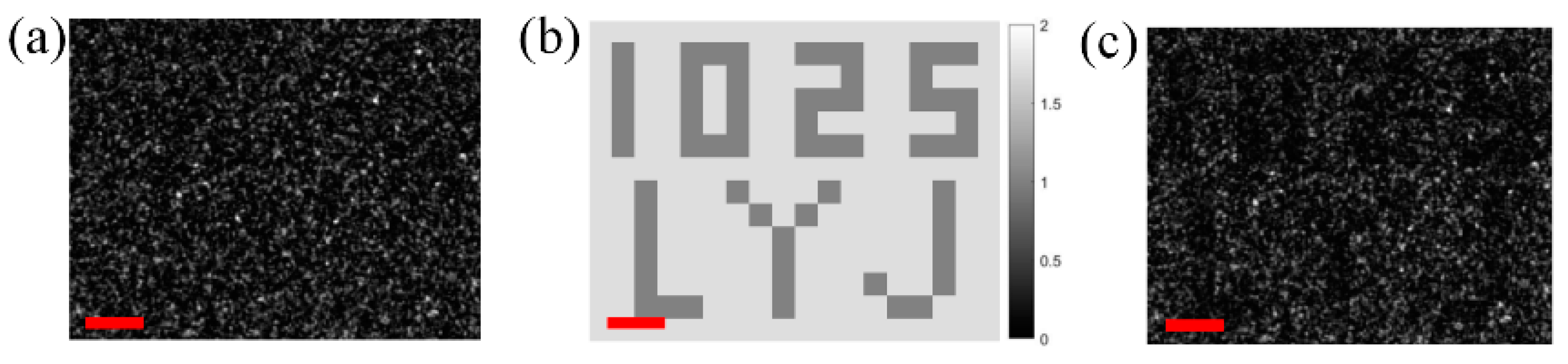
3.3. Verify the Effectiveness of the Round-Trip TM

In this part, to verify the effectiveness of our round-trip TM method, we will show that the illumination wave is indeed seriously distorted (for simplicity, only the amplitude is tested, and it can be predicted that the phase will get the same result). In such a case, the traditional one-way TM is ineffective.
Firstly, we have recorded the intensity (amplitude) distribution of the illumination wave (corresponding to S ( ξ , η ) in Figure 1) by placing a CCD in the place of the DMD, the result is shown in Figure 6a. It is seen that the originally uniformed incident light is seriously distorted due to the on-the-way-in process via the scattering medium. Furthermore, we multiply the amplitude of the object [shown in Figure 6b] by Figure 6a to indicate the amplitude of the reflected wave indirectly (corresponding to R ( ξ , η ) in Figure 1). The result is shown in Figure 6c. It is seen that the amplitude information of the object [ O ( ξ , η ) ] is completely submerged. This means that, even adopting the traditional one-way imaging method using the one-way TM, Figure 6c might be the best recovery result instead of the Figure 5c1 which could be obtained adopting our round-trip imaging method using the round-trip TM.

4. Discussion

The pre-processing of our method is relatively complicated, as the round-trip TM of a scattering medium should be measured prior to image the object, which will usually take a few minutes. However, this is just a one-time procedure, once calibrated, the TM is effective continuously as long as the medium has not been disturbed.
Our method is effective for imaging through the thick scattering medium, and it does not involve any scanning operations during the imaging process. Therefore, it probably has potential applications in some new fields. On one hand, one can monitor the target through an apparently opaque screen (used as a barrier), while it is incapable of being observed by it. On the other hand, instead of as a barrier which undermines the imaging ability, a scattering medium can also be used actively as an imaging sensor. For example, the single multimode optical fiber, as a scattering medium due to the mode dispersion, could potentially open up new, less invasive forms of endoscopy to perform high-resolution imaging of tissues out of reach of current conventional endoscopes [19,25,26].
At present, the preliminary result shows that our method has the ability to recover the complex amplitude information of the object. However, as an early study, no real 3D object has been tested yet. In fact, many problems should be further resolved when imaging a real 3D object. For example, the 2π ambiguity problem when there is an abrupt change in surface height of the object. This problem could can be solved if the size of the DMD segment that used to measure the TM is further reduced.

5. Conclusions

In conclusion, based on the round-trip TM, we have done some preliminary studies on imaging 3D objects hidden behind highly scattering media. A simple virtual complex amplitude object has been tested, and the results show that both the amplitude and the phase information of the object can be recovered. As an early study, this work may have potential reference value for the endoscopic imaging with more research.

Author Contributions

Funding acquisition, L.R. and Z.H.; Investigation, B.Z., C.X., Y.G., G.Z. and H.C.; Methodology, B.Z.; Supervision, L.R.; Validation, B.Z. and C.X.; Writing—original draft, B.Z.; Writing—review & editing, L.R.

Funding

This work was supported by the National Natural Science Foundation of China (Grant No. 61535015).

Conflicts of Interest

The authors declare no conflict of interest.

References

  1. Das, B.B.; Yoo, K.M.; Alfano, R.R. Ultrafast time-gated imaging in thick tissues: A step toward optical mammography. Opt. Lett. 1993, 18, 1092–1094. [Google Scholar] [CrossRef] [PubMed]
  2. Yoo, K.M.; Liu, F.; Alfano, R.R. Imaging through a scattering wall using absorption. Opt. Lett. 1991, 16, 1068–1070. [Google Scholar] [CrossRef] [PubMed]
  3. Sappey, A.D. Optical imaging through turbid media with a degenerate four wave mixing correlation time gate. Appl. Opt. 1994, 33, 8346–8354. [Google Scholar] [CrossRef] [PubMed]
  4. Ambekar, R.; Lau, T.-Y.; Walsh, M.; Bhargava, R.; Toussaint, K.C. Quantifying collagen structure in breast biopsies using second-harmonic generation imaging. Biomed. Opt. Exp. 2012, 3, 2021–2035. [Google Scholar] [CrossRef] [PubMed]
  5. Paciaroni, M.; Linne, M. Single-shot, two-dimensional ballistic imaging through scattering media. Appl. Opt. 2004, 43, 5100–5109. [Google Scholar] [CrossRef] [PubMed]
  6. Ren, Y.; Si, J.; Tan, W.; Zheng, Y.; Tong, J.; Hou, X. Speckle Suppression of OKG Imaging in Highly Turbid Medium Using SC-Assisted Fundamental Frequency. IEEE Photon. Technol. Lett. 2017, 29, 106–109. [Google Scholar] [CrossRef]
  7. Shapiro, J.H. Computational ghost imaging. Phys. Rev. A 2008, 78, 061802. [Google Scholar] [CrossRef]
  8. Bromberg, Y.; Katz, O.; Silberberg, Y. Ghost imaging with a single detector. Phys. Rev. A 2009, 79, 053840. [Google Scholar] [CrossRef]
  9. Vellekoop, I.M.; Mosk, A.P. Focusing coherent light through opaque strongly scattering media. Opt. Lett. 2007, 32, 2309–2311. [Google Scholar] [CrossRef] [PubMed]
  10. Horstmeyer, R.; Ruan, H.; Yang, C. Guidestar-assisted wavefront-shaping methods for focusing light into biological tissue. Nat. Photonics 2015, 9, 563–571. [Google Scholar] [CrossRef] [PubMed] [Green Version]
  11. Bertolotti, J.; van Putten, E.G.; Blum, C.; Lagendijk, A.; Vos, W.L.; Mosk, A.P. Non-invasive imaging through opaque scattering layers. Nature 2012, 491, 232–234. [Google Scholar] [CrossRef] [PubMed] [Green Version]
  12. Katz, O.; Heidmann, P.; Fink, M.; Gigan, S. Non-invasive real-time imaging through scattering layers and around corners via speckle correlations. Nat. Photonics 2014, 8, 784–790. [Google Scholar] [CrossRef]
  13. Wu, T.; Dong, J.; Shao, X.; Gigan, S. Imaging through a thin scattering layer and jointly retrieving the point-spread-function using phase-diversity. Opt. Exp. 2017, 25, 27182–27194. [Google Scholar] [CrossRef] [PubMed]
  14. Beenakker, C.W.J. Random-matrix theory of quantum transport. Rev. Mod. Phys. 1997, 69, 731–808. [Google Scholar] [CrossRef] [Green Version]
  15. Popoff, S.M.; Lerosey, G.; Carminati, R.; Fink, M.; Boccara, A.C.; Gigan, S. Measuring the transmission matrix in optics: an approach to the study and control of light propagation in disordered media. Phys. Rev. Lett. 2010, 104, 100601. [Google Scholar] [CrossRef] [PubMed]
  16. Popoff, S.; Lerosey, G.; Fink, M.; Boccara, A.C.; Gigan, S. Image transmission through an opaque material. Nat. Commun. 2010, 1, 81. [Google Scholar] [CrossRef] [PubMed]
  17. Choi, Y.; Yang, T.D.; Fang-Yen, C.; Kang, P.; Lee, K.J.; Dasari, R.R.; Feld, M.S.; Choi, W. Overcoming the diffraction limit using multiple light scattering in a highly disordered medium. Phys. Rev. Lett. 2011, 107, 023902. [Google Scholar] [CrossRef] [PubMed]
  18. Le, M.; Wang, G.; Zheng, H.; Liu, J.; Zhou, Y.; Xu, Z. Underwater computational ghost imaging. Opt. Exp. 2017, 25, 22859–22868. [Google Scholar] [CrossRef] [PubMed]
  19. Papadopoulos, I.N.; Farahi, S.; Moser, C.; Psaltis, D. High-resolution, lensless endoscope based on digital scanning through a multimode optical fiber. Biomed. Opt. Exp. 2013, 4, 260–270. [Google Scholar] [CrossRef] [PubMed]
  20. Kim, M.; Choi, Y.; Yoon, C.; Choi, W.; Kim, J.; Park, Q.-H.; Choi, W. Maximal energy transport through disordered media with the implementation of transmission eigenchannels. Nat. Photonics 2012, 6, 583–585. [Google Scholar] [CrossRef]
  21. Mounaix, M.; Andreoli, D.; Defienne, H.; Volpe, G.; Katz, O.; Grésillon, S.; Gigan, S. Spatiotemporal coherent control of light through a multiply scattering medium with the Multi-Spectral Transmission Matrix. Phys. Rev. Lett. 2016, 116, 253901. [Google Scholar] [CrossRef] [PubMed]
  22. Chaigne, T.; Katz, O.; Boccara, A.C.; Fink, M.; Bossy, E.; Gigan, S. Controlling light in scattering media non-invasively using the photoacoustic transmission matrix. Nat. Photonics 2013, 8, 58–64. [Google Scholar] [CrossRef] [Green Version]
  23. Zhuang, B.; Xu, C.; Geng, Y.; Zhao, G.; Chen, H.; He, Z.; Wu, Z.; Ren, L. Round-trip imaging through scattering media based on optical transmission matrix. Chin. Opt. Lett. 2018, 16, 041102. [Google Scholar] [CrossRef]
  24. Yamaguchi, I.; Zhang, T. Phase-shifting digital holography. Opt. Lett. 1997, 22, 1268–1270. [Google Scholar] [CrossRef] [PubMed]
  25. Choi, Y.; Yoon, C.; Kim, M.; Yang, T.D.; Fang-Yen, C.; Dasari, R.R.; Lee, K.J.; Choi, W. Scanner-Free and Wide-Field Endoscopic Imaging by Using a Single Multimode Optical Fiber. Phys. Rev. Lett. 2012, 109, 203901. [Google Scholar] [CrossRef] [PubMed]
  26. Psaltis, D.; Moser, C. Imaging with multimode fibers. Opt. Photonics News 2016, 27, 24–31. [Google Scholar] [CrossRef]
Figure 1. Schematic of imaging an object hidden behind a scattering medium.
Applsci 08 01036 g001
Figure 2. Experimental setup. Scattering medium (a 220-grit and a 1500-grit Thorlabs Optics ground-glass diffuser are stacked together to enhance the scattering ability), DMD: digital micromirror devices (ViALUX, V-7001VIS, 1024 × 768 pixels), LCVR: liquid crystal variable retarder (Meadowlark Optics, D5020), CCD (Hamamatsu, C13440-20CU, 2048 × 2048 segments (pixels), the central 400 × 300 segments are used for imaging), L#: lens, P#: polarizer, BS#: beam splitter, A: attenuation film, M: mirror.
Applsci 08 01036 g002
Figure 3. Sketch map of the measured round-trip TM T O E ( x , y ; ξ , η ) . Amplitude (a) and corresponding phase (b), respectively. Color bar: phase in radian.
Applsci 08 01036 g003
Figure 4. Complex amplitude object constructed by the SLM using two phase masks O SLM ( 1 ) ( ξ , η ) and O SLM ( 2 ) ( ξ , η ) . (a) amplitude = 1 and phase = π / 3 for the characters part, (b) amplitude = 3 and phase = - π / 6 for the background part.
Applsci 08 01036 g004
Figure 5. Imaging the complex amplitude object. (a1,a2) Amplitude and phase of the object O SLM ( 2 ) ( ξ , η ) O SLM ( 1 ) ( ξ , η ) , respectively. (b1,b2) Amplitude and phase of the corresponding output optical filed E CCD ( 2 ) ( x , y ) E CCD ( 1 ) ( x , y ) , respectively. (c1,c2) Amplitude and phase of the recovered object, respectively. (d1) Section profiles corresponding to the lines in (a1,c1); (d2) section profiles corresponding to the lines in (a2,c2). Scale bars indicate 400 µm in (b1,b2) and 600 μm in (a1,a2,c1,c2). Gray bar: amplitude. Color bar: phase in radian.
Applsci 08 01036 g005
Figure 6. (a) Intensity (amplitude) distribution of the illumination wave. (b) Amplitude of the object. (c) Amplitude of the reflected wave. Scale bar: 550 µm.
Applsci 08 01036 g006

