Solar Tower Power Plants of Molten Salt External Receivers in Algeria: Analysis of Direct Normal Irradiation on Performance

 , and
, and
Abstract
:1. Introduction
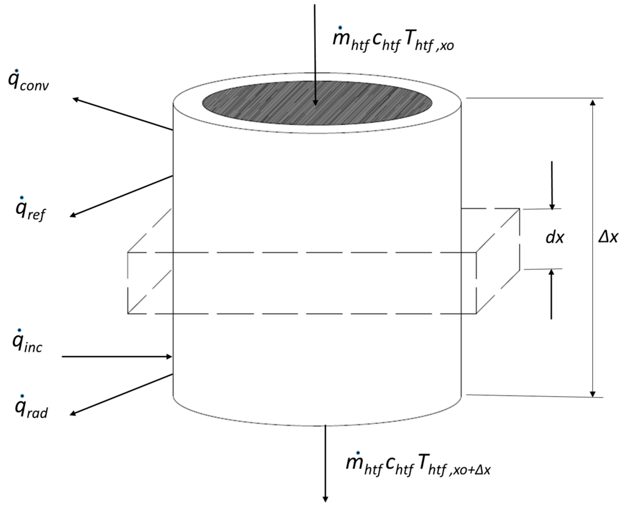
2. Methodology
3. Results
3.1. Region of Béchar
3.2. Region of El Oued
3.3. Region of Djelfa
3.4. Optimization of the Field of Heliostats
4. Discussion
5. Conclusions
Author Contributions
Funding
Acknowledgments
Conflicts of Interest
Nomenclature
| STPP | Solar tower power plants |
| DNI | Direct normal irradiation |
| DHI | Diffuse horizontal irradiation |
| GHI | Global horizontal irradiation |
| SAM | System advisor module |
| SM | Solar multiple |
| TES | Thermal energy storage (h) |
| CSP | Concentrated solar power |
| ΔR | Radial distance between heliostats (m) |
| ΔAZ | Azimuthal distance between heliostats (m) |
| θ | Receiver elevation angle from heliostat (°) |
| α | Heliostat loft angle in degree (°) |
| Ah | Surface heliostat (m²) |
| Id | Irradiation direct normal (W/m²) |
| Nh | Number of heliostats. |
| Nt | Total number of the receiver tube |
| Efficiency of the solar field | |
| Loss due to cosine effect | |
| Loss due to shading effect | |
| Loss due to blocking effect | |
| Loss due to overflow | |
| Loss due to reflection | |
| Losses due to dispersal | |
| CF | Capacity factor |
| Egp | Energy generated in part-time (W) |
| Egf | Energy generated in full-time (W) |
| TMY | Typical Meteorological Year |
| Qréc | Heat flow of the receiver (W) |
| Qinc | Incident heat flow (W) |
| qra | Loss of radiant heat flux (W) |
| qconv | Loss of convection heat flux (W) |
| qref | Loss of reflection flow (W) |
| qsf | Energy generated by the field of heliostats (W) |
| qpb | Energy required by the power block (W) |
| Qh | Heat flow of molten salt (W) |
| Si | Total surface/Surface total (m²) |
| USi | Heat transfer conductance coefficient (W/K) |
| mhtf | Molten salt flow rate (kg/s) |
| Chtf | Heat capacity of the molten salt fluid (kJ/kg·K) |
| Tst | Receiver temperature at the surface (K) |
| Thtf | Inlet temperature of the molten salt at x position (K) |
| Tic-air | Temperature of the air in the inner cavity (K) |
| Rconv | Heat transfer resistance by convection (K/W) |
| Rcond | Heat transfer resistance by conduction (K/W) |
| Dit | Inner diameter of the tube (m) |
| Dot | Outer diameter of the tube (m) |
| hhtf | Convection heat transfer of the molten salt (W/m²·K) |
| hconv | Convective heat losses from receiver tube (W/m2·K) |
| Kt | Thermal conductivity of the receiver tube (W/m·K) |
| Lt | Length of the tube (m) |
| TRY | Test Reference Year |
| EPW | Energy Plus Weather |
| CSV | Comma Separated Value |
| WM | Heliostat width meters |
| HM | Heliostat height meters |
| HTF | Heat transfer fluid |
References
- Boudghene, S.; Khiat, Z.; Flazi, S.; Kitamura, Y. A review on the renewable energy development in Algeria: Current perspective, energy scenario and sustainability issues. Renew. Sustain. Energy Rev. 2012, 16, 4445–4460. [Google Scholar] [CrossRef]
- Stambouli, A.B. Promotion of renewable energies in Algeria: Strategies and perspectives. Renew. Sustain. Energy Rev. 2011, 15, 1169–1181. [Google Scholar] [CrossRef]
- Energies Nouvelles, Renouvelables et Maitrise de l’Energie. Available online: http://www.energy.gov.dz/francais/index.php?page=energies-nouvelles-renouvelables-et-maitrise-de-l-energie (accessed on 22 May 2018).
- Medium Term RE Market Report, Agence Internationale de l’Energie. 2013. Available online: https://www.iea.org/publications/freepublications/publication/2013MTRMR.pdf (accessed on 22 May 2018).
- Ghezloun, A.; Chergui, S.; Oucher, N. Algerian energy strategy in the context of sustainable development (Legal framework). Energy Procedia 2011, 6, 319–324. [Google Scholar] [CrossRef]
- Portail Algériеn des Enеrgiеs Rеnouvе𝗅ab𝗅еs. Available online: https://portail.cder.dz/spip.php? article4446 (accessed on 22 May 2018).
- Imadojemu, H.E. Concentrating parabolic collectors: A patent survey. Energy Convers. Manag. 1995, 36, 225–237. [Google Scholar] [CrossRef]
- Hocine Moussa, B. Thermal Solar Power Plants in Algeria and Desertec Mega project. In Proceedings of the Le 1erés Journées d’Etudes de Mécaniques, Batna, Algeria, 29–30 November 2011. [Google Scholar]
- Rosen, M.A.; Dincer, I. Exergy–cost–energy–mass analysis of thermal systems and processes. Energy Convers. Manag. 2003, 4, 1633–1651. [Google Scholar] [CrossRef]
- Adinberg, R. Simulation analysis of thermal storage for concentrating solar power. Appl. Therm. Eng. 2011, 31, 3588–3594. [Google Scholar] [CrossRef]
- Wellmann, J.; Morosuk, T. Renewable Energy Supply and Demand for the City of El Gouna, Egypt. Sustainability 2016, 8, 314. [Google Scholar] [CrossRef]
- Annuaire de la Filière Française du Solaire Thermodynamique. 2011. Available online: http://www.enr.fr/userfiles/files/Annuaires/2011171733_annuairethermo2011.pdf (accessed on 22 May 2018).
- Ho, C.K.; Iverson, B.D. Review of high-temperature central receiver designs for concentrating solar power. Renew. Sustain. Energy Rev. 2014, 29, 835–846. [Google Scholar] [CrossRef]
- Boudaoud, S.; Khellaf, A.; Mohammedi, K.; Behar, O. Thermal performance prediction and sensitivity analysis for future deployment of molten salt cavity receiver solar power plants in Algeria. Energy Convers. Manag. 2015, 89, 655–664. [Google Scholar] [CrossRef]
- Behar, O.; Khellaf, A.; Mohammedi, K. A review of studies on central receiver solar thermal power plants. Renew. Sustain. Energy Rev. 2013, 23, 12–39. [Google Scholar] [CrossRef]
- Mihoub, S.; Chermiti, A.; Beltagy, H. Methodology of determining the optimum performances of future concentrating solar thermal power plants in Algeria. Energy 2017, 122, 801–810. [Google Scholar] [CrossRef]
- Quaschning, V. Technical and economical system comparison of photovoltaic and concentrating solar thermal power systems depending on annual global irradiation. Sol. Energy 2004, 77, 171–178. [Google Scholar] [CrossRef]
- Zhu, Y.; Zhai, R.; Yang, Y.; Reyes-Belmonte, M.A. Techno-Economic Analysis of Solar Tower Aided Coal-Fired Power Generation System. Energies 2017, 10, 1392. [Google Scholar] [CrossRef]
- Toro, C.; Rocco, M.V.; Colombo, E. Exergy and Thermoeconomic Analyses of Central Receiver Concentrated Solar Plants Using Air as Heat Transfer Fluid. Energies 2016, 9, 885. [Google Scholar] [CrossRef] [Green Version]
- Boukelia, T.E.; Mecibah, M.S. Parabolic trough solar thermal power plant: Potential, and projects development in Algeria. Renew. Sustain. Energy Rev. 2013, 21, 288–297. [Google Scholar] [CrossRef]
- Boudaoud, S.; Khellaf, A.; Mohammedi, K. Solar tower plant implementation in northern Algeria: Technico economic assessment. In Proceedings of the 2013 5th International Conference on Modeling, Simulation and Applied Optimization (ICMSAO), Hammamet, Tunisia, 28–30 April 2013; pp. 1–6. [Google Scholar]
- Larbi, S.; Bouhdjar, A.; Chergui, T. Performance analysis of a solar chimney power plant in the southwestern region of Algeria. Renew. Sustain. Energy Rev. 2010, 14, 470–477. [Google Scholar] [CrossRef]
- Viebahn, P.; Lechon, Y.; Trieb, F. The potential role of concentrated solar power (CSP) in Africa and Europe. A dynamic assessment of technology development, cost development and life cycle inventories until 2050. Energy Policy 2011, 39, 4420–4430. [Google Scholar] [CrossRef]
- Abbas, M.; Merzouk, N.K. Techno economic study of solar thermal power plants for centralized electricity generation in Algeria. In Proceedings of the 2012 2nd International Symposium on Environment Friendly Energies and Applications, Newcastle upon Tyne, UK, 25–27 June 2012. [Google Scholar]
- Freeman, J.M.; DiOrio, N.A.; Blair, N.J.; Neises, T.W.; Wagner, M.J.; Gilman, P.; Janzou, S. System Advisor Model (SAM) General Description (Version 2017.9.5); Technical Report for National Renewable Energy Laboratory: Golden, CO, USA, May 2018. [Google Scholar]
- Ouagued, M.; Khellaf, A.; Loukarfi, L. Estimation of the temperature, heat gain and heat loss by solar parabolic trough collector under Algerian climate using different thermal oils. Energy Convers. Manag. 2013, 75, 191–201. [Google Scholar] [CrossRef]
- Gilman, P.; Blair, N.; Mehos, M.; Christensen, C.; Janzou, S.; Cameron, C. Solar Advisor Model. User Guide for version 2.0; Technical report NREL/TP-670-43704; August 2008. Available online: https://www.nrel.gov/docs/fy08osti/43704.pdf (accessed on 22 may 2018).
- Kistler, B.L. A User’s Manual for DELSOL3. A Computer Code for Calculating the Optical Performance and Optimal System Design for Solar Thermal Central Receiver Plants. SAND86-8018. Unlimited release UC-62a. 1986. Available online: http://ciTESeerx.ist.psu.edu/viewdoc/download?doi=10.1.1.467.8372&rep=rep1&type=pdf (accessed on 22 May 2018).
- Ho, C.K. Overview of Concentrating Solar Power Research at Sandia (Feb 2017); Sandia National Lab.: Albuquerque, NM, USA, 2017. [Google Scholar]
- Huang, W. Development of an analytical method and its quick algorithm to calculate the solar energy collected by a heliostat field in a year. Energy Convers. Manag. 2014, 83, 110–118. [Google Scholar] [CrossRef]
- Wagner, M.J. Simulation and Predictive Performance Modeling of Utility Scale Central Receiver System Power Plants. Ph.D. Thesis, University of Wisconsin-Madison, Madison, WI, USA, January 2008. [Google Scholar]
- Romero-Álvarez, M.; Zarza, E. Concentrating solar thermal power. In Handbook of Energy Efficiency and Renewable Energy; CRC Press: Boca Raton, FL, USA, 2007. [Google Scholar]
- Modeling and Calculation of Heat Transfer Relationship for Concentrated Solar Power Receivers. Available online: https://search.library.wisc.edu/catalog/9910121576302121 (accessed on 30 May 2018).
- ReGrid: Concentrated Solar Power. (RENAC) Renewables Academy. Schonhauser Alee 10–11. 10119. Berlin, Germany. Available online: https://www.renac.de/en/projects/ (accessed on 22 May 2018).
- German Aerospace Centre (DLR). Available online: https://www.dlr.de/dlr/en/desktopdefault.aspx/tabid-10002/ (accessed on 30 May 2018).
- Centre de Developpement des Energies Renouvelables (CEDER). Algeria (2013). Available online: http://www.cder.dz/ (accessed on 2 June 2018).
- Siva Reddy, V.; Kaushik, S.C.; Ranjan, K.R.; Tyagi, S.K. State of the art of solar thermal power plants. A review. Renew. Sustain. Energy Rev. 2013, 27, 258–273. [Google Scholar] [CrossRef]
- Cheng, T.C.; Yang, C.K.; Lin, I. Biaxial-Type Concentrated Solar Tracking System with a Fresnel Lens for Solar-Thermal Applications. Appl. Sci. 2016, 6, 115. [Google Scholar] [CrossRef]
- Ohya, Y.; Wataka, M.; Watanabe, K.; Uchida, T. Laboratory Experiment and Numerical Analysis of a New Type of Solar Tower Efficiently Generating a Thermal Updraft. Energies 2016, 9, 1077. [Google Scholar] [CrossRef]
- Gregorio-Muñiz, J.M. El Mercado de las Energías Renovables en Argelia. Oficina Económica y Comercial de la Embajada de España en Argel. 2004. Available online: https://www.icex.es/icex/ (accessed on 2 June 2018).
- Owen, A.D. Renewable energy: Externality costs as market barriers. Energy Policy 2006, 34, 632–642. [Google Scholar] [CrossRef]
- Pitz-Paal, R.; Botero, N.B.; Steinfeld, A. Heliostat field layout optimization for high-temperature solar thermochemical processing. Sol. Energy 2011, 85, 334–343. [Google Scholar] [CrossRef]
- Zhang, H.L.; Baeyens, J.; Degrève, J.; Cacères, G. Concentrated solar power plants: Review and design methodology. Renew. Sustain. Energy Rev. 2013, 22, 466–481. [Google Scholar] [CrossRef]
- Candelario-Garrido, A.; García-Sanz-Calcedo, J.; Reyes, A.M. A quantitative analysis on the feasibility of 4D planning graphic systems versus conventional systems in building projects. Sustain. Cities Soc. 2017, 35, 378–384. [Google Scholar] [CrossRef]


| Parameter | Design Parameters | Djelfa | El Oued | Béchar |
|---|---|---|---|---|
| Location | DNI (W/m2) | 1050.00 | 750.00 | 700.00 |
| Latitude (°) | 34.68 | 33.50 | 31.50 | |
| Longitude (°) | 3.25 | 6.78 | −2.25 | |
| Elevation (m) | 1144.00 | 69.00 | 816.00 |
| Parameter | Design Parameters | Value |
|---|---|---|
| Field of heliostats | Surface of the heliostat (m²) | 144.00 |
| Tower and receiver | Diameter of pipes (mm) Thickness of pipes (mm) Type of pipe material (stainless steel) | 60.00 1.25 |
| Fluid | Heat transfer fluid (HTF) type | 60% NaNO3, 40% KNO3 |
| Coolant | Input temperature (°C) Output temperature (°C) | 565.00 290.00 |
| Power block | Design turbine output (MWe) Thermodynamic cycle efficiency (%) Operating pressure of the boiler (bar) Type of cooling capacitor | 820.00 37.00 100.00 Air |
| Energy storage | Type of storage Load storage in full hours | 2 tanks 0–12 h |
| Type of Parameter | Simulated Case, Scenario 1 [14] | Simulated Case, Scenario 2 [14] | Simulated Case, Study |
|---|---|---|---|
| Annual DNI (kWh/m2) | 1907.30 | 1907.30 | 2416.30 |
| Hybridization (%) | 0.00 | 15.00 | 0.00 |
| Net energy production (GWh/year) | 18.15 | 44.40 | 18.45 |
| Net energy production difference (%) | 1.60 (scenario 1.00 and study) | ||
| Annual capacity factor (%) | 10.60 | 26.00 | 10.50 |
© 2018 by the authors. Licensee MDPI, Basel, Switzerland. This article is an open access article distributed under the terms and conditions of the Creative Commons Attribution (CC BY) license (http://creativecommons.org/licenses/by/4.0/).
Share and Cite
Rouibah, A.; Benazzouz, D.; Kouider, R.; Al-Kassir, A.; García-Sanz-Calcedo, J.; Maghzili, K. Solar Tower Power Plants of Molten Salt External Receivers in Algeria: Analysis of Direct Normal Irradiation on Performance. Appl. Sci. 2018, 8, 1221. https://0-doi-org.brum.beds.ac.uk/10.3390/app8081221
Rouibah A, Benazzouz D, Kouider R, Al-Kassir A, García-Sanz-Calcedo J, Maghzili K. Solar Tower Power Plants of Molten Salt External Receivers in Algeria: Analysis of Direct Normal Irradiation on Performance. Applied Sciences. 2018; 8(8):1221. https://0-doi-org.brum.beds.ac.uk/10.3390/app8081221
Chicago/Turabian StyleRouibah, Abdelkader, Djamel Benazzouz, Rahmani Kouider, Awf Al-Kassir, Justo García-Sanz-Calcedo, and K. Maghzili. 2018. "Solar Tower Power Plants of Molten Salt External Receivers in Algeria: Analysis of Direct Normal Irradiation on Performance" Applied Sciences 8, no. 8: 1221. https://0-doi-org.brum.beds.ac.uk/10.3390/app8081221