Line Beam Scanning-Based Ultra-Fast THz Imaging Platform

1
Department of Information Physics & Engineering, Nanjing University of Science and Technology, Nanjing 210094, Jiangsu, China
2
Institute of Fluid Physics, China Academy of Engineering Physics, Mianyang 621900, Sichuan, China
3
School of Manufacturing Science and Engineering, Southwest University of Science and Technology, Mianyang 621010, Sichuan, China
*
Author to whom correspondence should be addressed.
Appl. Sci. 2019, 9(1), 184; https://0-doi-org.brum.beds.ac.uk/10.3390/app9010184
Submission received: 7 December 2018
/
Revised: 27 December 2018
/
Accepted: 2 January 2019
/
Published: 7 January 2019
(This article belongs to the Section Optics and Lasers)
Abstract
:Featured Application
The work could be applied to the field of human body security.
Abstract
In order to realize rapid THz detecting and imaging, a line beam scanning-based ultra-fast THz imaging platform is designed combining simple optical components and lightweight mechanical system. The designed THz imaging platform has the resolution of 12 mm, the scanning angle range of ±10.5°, the scanning speed of 0.17 s/frame, and the scanning range of 2 m × 0.8 m; moreover, it can realize rapid human body THz imaging and distinguish metallic objects. Considering its high-quality performance in THz imaging and detecting, it is believed the proposed line beam scanning-based ultra-fast THz imaging platform can be used in the future in various safe screening applications.
1. Introduction
In order to contain the increasing threat of terrorism, public security screening systems, especially at airports and railway stations, are becoming increasingly significant. Classical security screening systems include metal scanners for people and X-ray detectors for luggage and have been widely used [1,2,3,4]. Unfortunately, these traditional techniques are no longer capable of fulfilling the demands due to their low detection efficiency and high false alarm rate; therefore, developing rapid and precise security screening system is required [5,6].
Recently developed X-ray imaging can easily detect contraband, even concealed under cloths due to the strong X-ray absorption by metals [7,8,9]. However, considering its high photon energy and ionizing potential, it is harmful to human bodies and only suited for luggage detections. Different from X-ray imaging, THz imaging can also provide target details in another perspective [10,11,12,13,14,15,16]: After penetrating the cloths, THz wave is often absorbed by the human body but strongly reflected by metals; therefore, the received reflected THz wave marks the metallic objects [17]. Compared to X-ray, THz wave has a much lower frequency band, which is nonionizing and poses no known health risks [18,19,20,21,22], indicating that THz imaging is especially suitable for security screening for both people and luggage, though there is a lack of efficient sources and detectors [23,24,25]. The currently proposed THz imaging systems include two fundamental tactics based on synthetic aperture radar (SAR) [26,27] and multiple-input multiple-output (MIMO) [28,29,30,31], respectively. SAR-based THz imaging suffers from slow imaging efficiency for each scan, limiting their applications in high-speed security screening. In order to accelerate the efficiency, MIMO-based THz imaging can reduce the scanning time using parallel measurement with an entire array of transmitters and receivers, illustrating that MIMO-based THz imaging is preferred for high-speed security screening platform construction. Here, in order to further accelerate the THz imaging speed, as well as to simplify the system, a line beam scanning-based ultra-fast THz imaging platform is proposed. Its optical system is rather simple, only composed of a source/sensor chip for THz wave emitting and receiving, a cylindrical reflector for wavefront reshaping, and a scanning mirror for line beam scanning. To assemble the optical system, as well as to control the mirror for line beam scanning, a lightweight mechanical system is designed and fabricated. The designed THz imaging platform realizes human body scanning within 0.17 sec in a high resolution of 12 mm and easily distinguishes metallic objects, it is believed the proposed line scanning-based ultra-fast THz imaging platform is a potential tool for fast safe public screening applications.
2. Platform Design and Construction
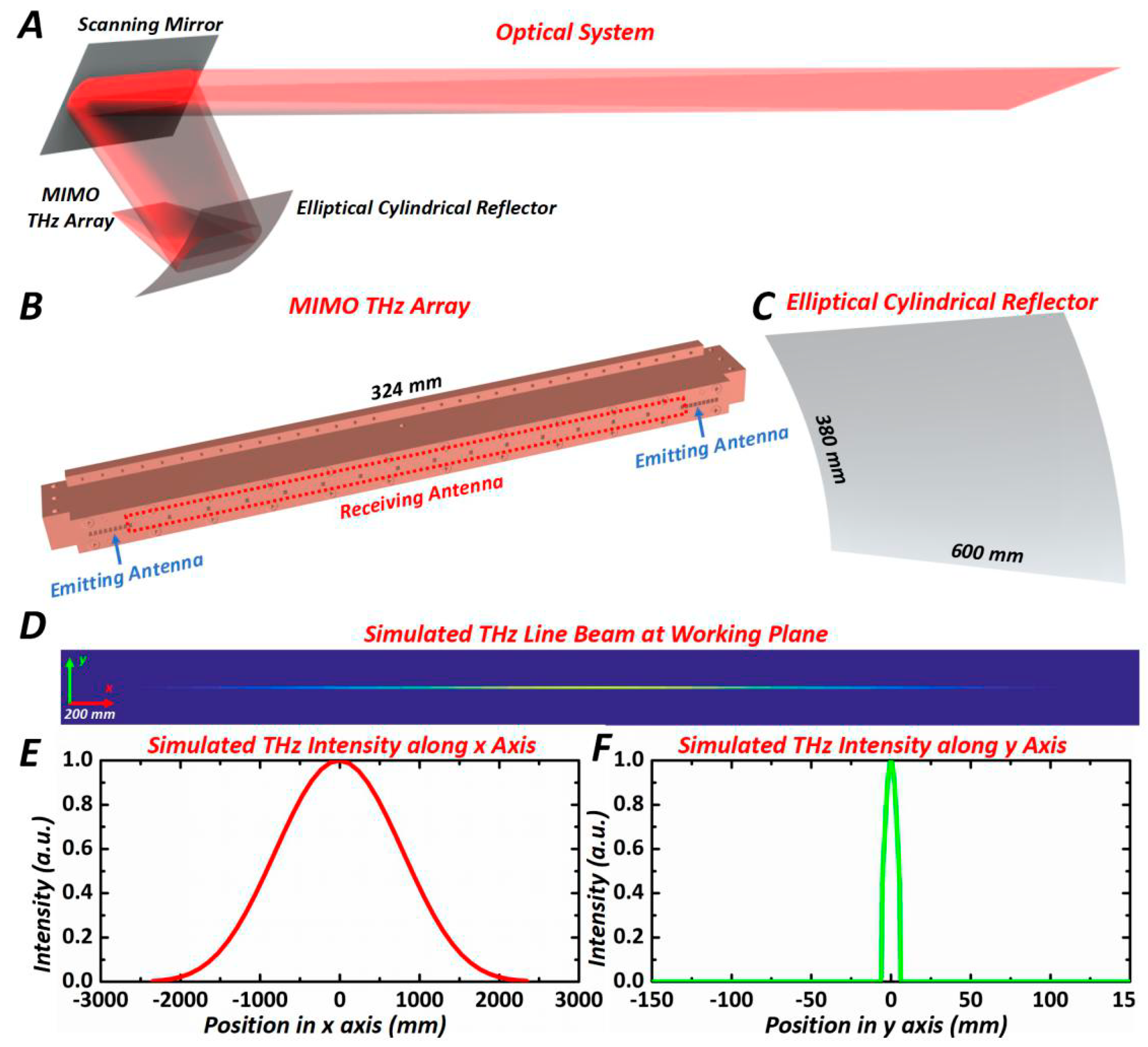
The optical system of the line beam scanning-based ultra-fast THz imaging platform shown in Figure 1A is rather simple, only composed of a source/sensor chip in Figure 1B, an elliptical cylindrical reflector in Figure 1C, and a scanning mirror in Figure 1A. The source/sensor chip not only emits THz spherical wavefront generated by the emitting antenna, but also detects the THz signals reflected from the target with the receiving antenna: The THz signal with the central frequency of 340 GHz, the bandwidth of 20 GHz, and the peak output power of 0.5 mW, is transmitted from the 4-Tx channels and generates a narrow beam line based on the optical system, and the reflected THz signal from the detecting sample is collected by all the 16-Rx channels. In our case, the THz wave is generated from microwave through frequency multiplication, in which the efficiencies are rather low in both emitting and receiving, much lower than the efficiencies of the THz generation based on photoconductive antenna [23,24,25], but a rather narrow wavelength band can often be maintained, which can hardly be achieved using photoconductive antenna. Moreover, an elliptical cylindrical reflector was used to reshape the spherical wavefront from the source into the cylindrical wavefront to generate the line beam, as well as to collect the reflected THz signals to the THz sensors. For the elliptical cylindrical reflector, two elliptical foci were conjugated, as the source/sensor chip was located at one focus, the line beam was well generated at another elliptical focus. Moreover, the scanning mirror can realize the line beam scanning with a rather large range and high speed. Considering the practical applications of the THz imaging platform, the distance between the working plane and the scanning mirror was set as 3 m, and the scanning range should reach 2 m × 0.8 m at the working plane. In order to optimize the optical system, ray tracing algorithm [32] was implemented: after inputting the parameters of the scanning mirror and the elliptical cylindrical reflector, as well as their positions, the THz intensity distribution can be estimated using multiple rays, and according to the numerically computed THz intensity distribution, the configuration of the elliptical cylindrical reflector was finally obtained: The optimized elliptical cylindrical reflector has the radius of the curvature of 554.1 mm and the Conic factor of −0.724. According to the optimized optical system, the intensity distribution at the working plane was then computed as shown in Figure 1D. It is shown that the length of the line beam can reach 0.8 m as provided by the central intensity distribution along the x-axis; besides, according to the central intensity distribution along the y-axis, the full width at half maximum (FWHM) reached 12 mm, indicating the resolution of the THz imaging platform. Via numerical simulations, it is proved that the designed optical system can achieve fast safe screening.
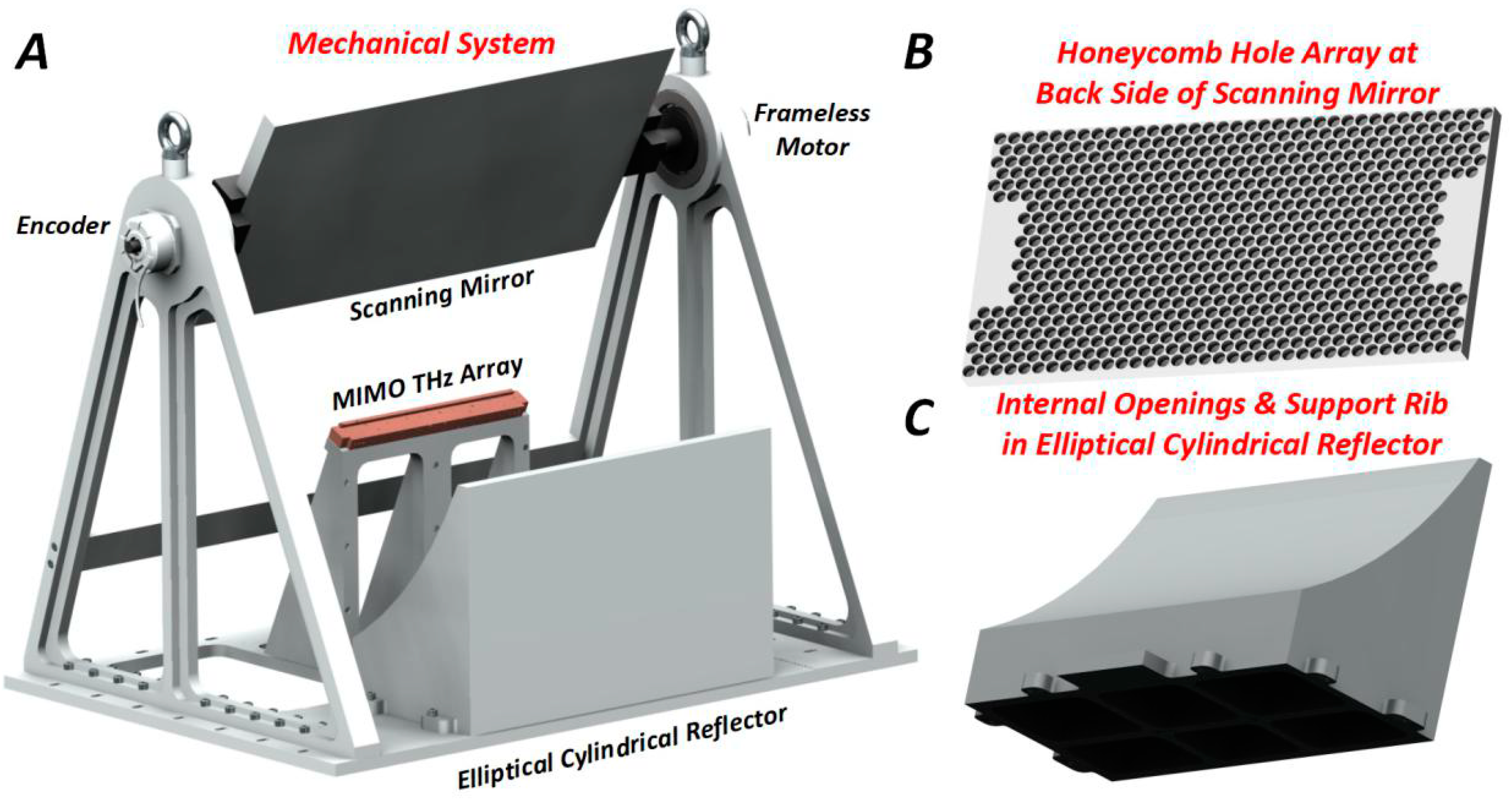
Next, the mechanical system of the line beam scanning-based ultra-fast THz imaging platform shown in Figure 2A was designed and constructed not only to assemble the optical system, but also to realize line beam scanning by controlling the scanning mirror. In order to realize lightweight design, super-hard aluminum alloy 7075 was used as the materials of both the mechanical system and the mirrors (including the elliptical cylindrical reflector and the scanning mirror); moreover, honeycomb hole array were drilled at the back side of the scanning mirror as shown in Figure 2B to further decrease its weight to 17 kg, which is 34% lighter than without hole drilling. Both the source/sensor chip and the elliptical cylindrical reflector with the size of 380 mm × 600 mm as shown in Figure 2C were fixed at the bottom of the mechanical system, and the scanning mirror with the size of 403 mm × 792 mm combining with the rotation motor (Kollmogen KBMS 43H03, USA, Radford) and the encoder (Heidenhain RCN 2380, Germany, Traunreut) was designed as the scanning section. The encoder chosen had 26-bit circular grating with a precision of ±5”; the rotation motor selected was frameless, which can obtain the rotation range larger than ±9°. Considering the weight of the scanning mirror was less than 250 N required by rotation motor, it is proved that the scanning section could realize the line beam scanning with high precision and a wide range. Moreover, with the quantitative analysis on the vibration mode of the whole mechanical system, its inherent frequency is around 47.7 Hz, much higher than that of the scanning mirror as 2.5 Hz; therefore, no resonance occurred during line beam scanning. In addition, the whole THz imaging platform including the source/sensor part and the mechanical part uses the power supply of 220 V AC, and the total power of the whole system is ~2500 W.
With the platform design and construction in both optical and mechanical systems, the main optimization on the THz imaging platform includes (1) optimizing the optical system composed of the elliptical cylindrical reflector and the scanning mirror to pursue high imaging resolution; (2) lightening the mechanical structure, and (3) precisely controlling the scanning using the rotation motor and the encoder to improve the mechanical system. After the design and construction of both the optical and mechanical systems, the performance of the line beam scanning-based ultra-fast THz imaging platform was tested, and it was then adopted for practical applications for safe screening on the human body, which are both described in the following section.
3. Experiments
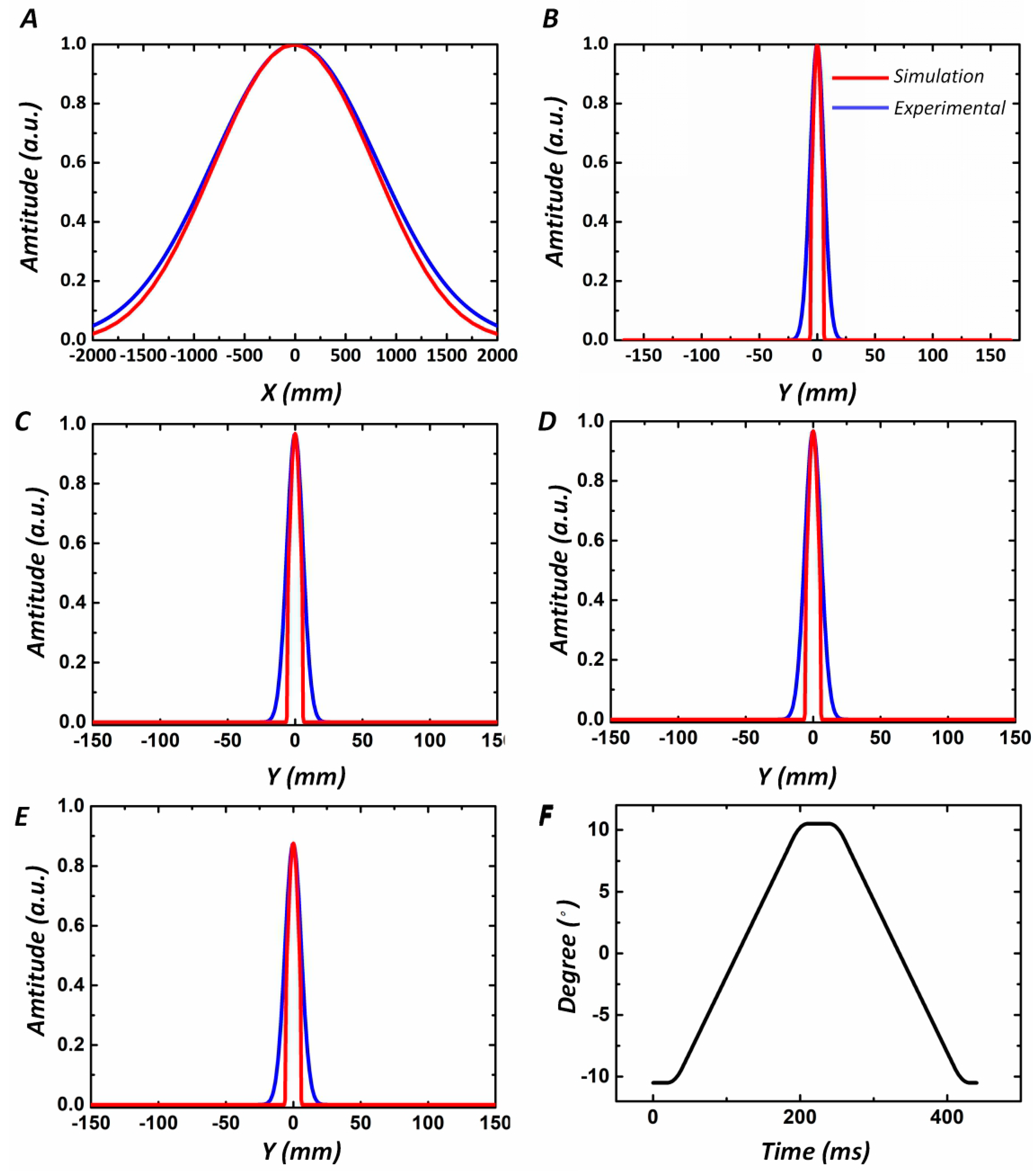
After designing and constructing the line beam scanning-based ultra-fast THz imaging platform, its performance was tested. The scanning mirror was adjusted to keep the optical axis parallel with the ground coordinate, and a Brunei tube working as a THz single point detector was scanned along the vertical direction to determine the optical axis position. The Brunei tube was scanned along the optical axis, since the intensity at the working plane should have the highest value, indicating that the distance between the working plane and the scanning mirror was 3.02 m. After the determination of the working plane, the Brunei tube was scanned in the working plane to measure the intensity distribution. The intensity distributions along the x and y axes (marked in Figure 1D) are shown in Figure 3A,B, respectively. There is a little difference between the numerically computed and practically measured results, it is often because the numerically calculated intensity distributions were obtained in the ideal condition which did not consider the aberration in the THz system caused by errors in the system fabrication and integration; however, these errors inevitably occurred in the designed THz imaging system, thus, broadening the THz intensity distribution; moreover, the noise of the THz detector also introduced background errors in THz intensity measurements, which also broadened the THz intensity distribution along the y-axis. Though intensity distribution broadened in the measured results, both the numerically computed and practically measured results are still close, via Gaussian fitting, it indicates that the FWHM of the measured line beam was 12.04 mm, close to the numerically evaluated FWHM as ~12 mm, proving the proposed THz imaging platform can reach the resolution of ~12 mm. Besides, both the numerically computed and practically measured intensity distributions along the y-axis with 200 mm, 300 mm, and 400 mm away from the central axis were also listed in Figure 3C–E, respectively. The coincidence between the numerically calculated and the practically measured results in Figure 3A–E proved the high-quality construction of the THz imaging platform. Since the line beam scanning-based THz imaging platform requires high-speed scanning for two-dimensional imaging, both the detecting region and the scanning speed were then measured. Figure 3F shows the scanning trajectory, indicating that the scanning speed could reach 170 ms/frame, the scanning range of the mirror was within ±10.5°, and the scanning range at the working plane could reach 2 m × 0.8 m, all satisfying the scanning requirements.
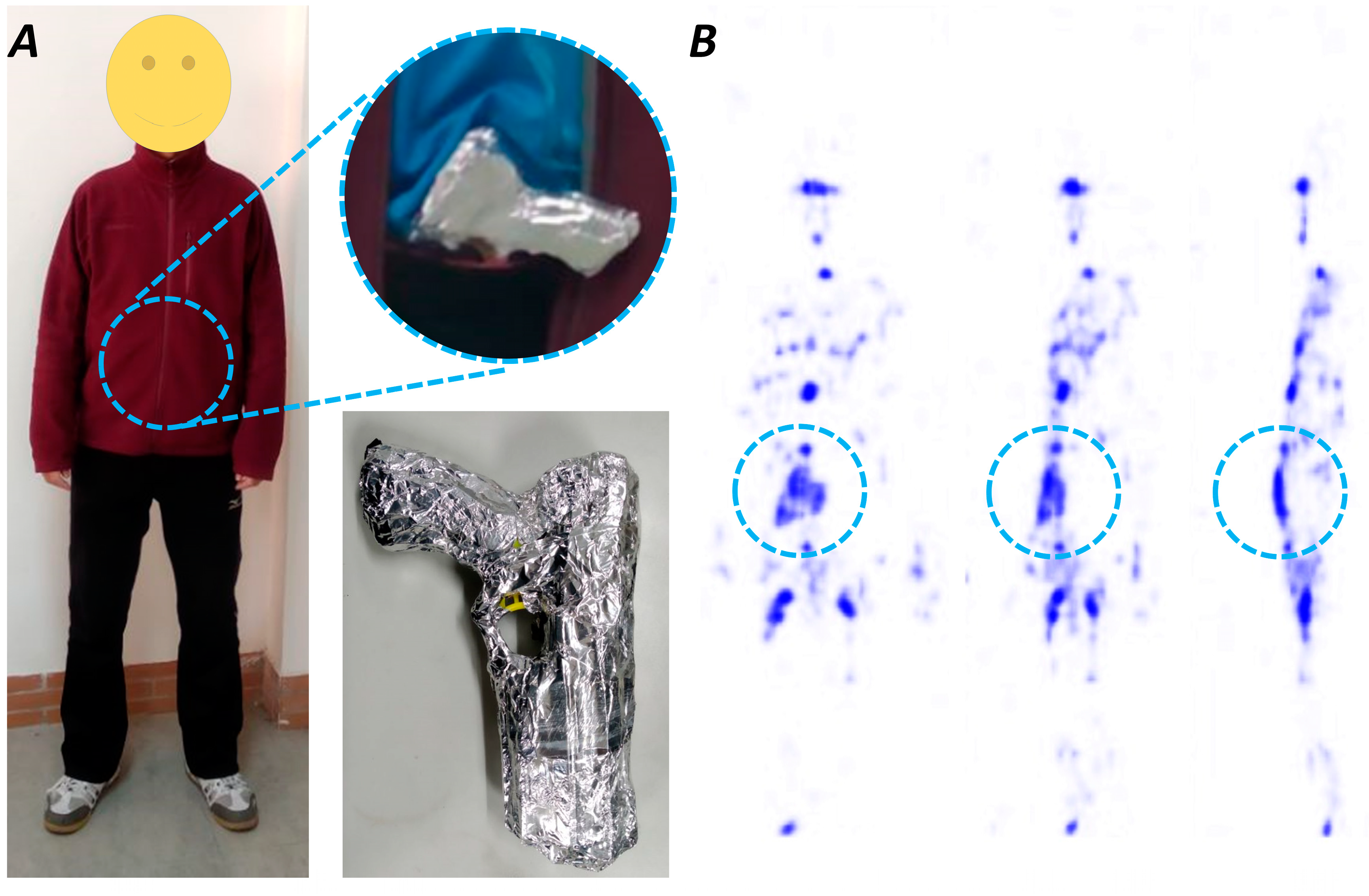
After the certification on the line beam scanning-based THz imaging platform, it was finally adopted in the safe screening of the human body THz imaging as shown in Figure 4. Both the images captured by the direct optical device and the proposed THz imaging platform provide information from different perspectives. With the reconstructed THz image, the metal fabricated objects as the metallic gun can be easily distinguished according to the high intensity of the collected THz signals as shown in Figure 4. However, besides the distinguished contraband, a few spots of high intensity still occurred in the THz image, some of them were generated by the THz signals reflected from the metallic parts such as the metallic zipper, and some of them were generated from the THz signals reflected from bones. However, with improved image processing methods [33,34], the contraband can be accurately distinguished according to their special configuration and reflectivity. Moreover, the line beam scanning-based ultra-fast THz imaging platform can realize complete human body imaging within 0.2 s, indicating high-speed scanning and imaging capability.
It is worth noting that the high relative humidity decreases the contrast in THz imaging due to the THz signal loss in the water vapor, therefore, high relative humidity affects the performance of the device. In our experiments, the THz imaging was implemented in an open environment with room temperature, and the image was captured with the relative humidity of ~60%, and the contrast is still satisfied since the metallic gun can be clearly distinguished, indicating that the proposed THz imaging platform can be adopted in practical applications.
Moreover, compared to the devices as PNNL [35,36], JPL [37,38], and TeraScreen [28,29], the proposed line beam scanning-based ultra-fast THz imaging platform still has high-quality performance in THz imaging. The scanning range of the proposed platform reaches 2 m × 0.8 m, which is comparable with the TeraScreen, but much larger than the 0.5 m × 0.5 m of JPL. The scanning speed of the proposed platform is 0.17 s/frame, a little lower than the 0.13 s/frame of TeraScreen, but still much faster than the 1 s/frame of JPL. According to its high-quality performance and practical application in safe screening of the human body, as well as the comparison with the existing systems, it is believed the proposed line beam scanning-based ultra-fast THz imaging platform can be adopted for THz imaging and detecting in various applications.
4. Conclusions
In order to realize ultra-fast THz detecting, a line beam scanning-based THz imaging platform has been designed and constructed in this paper. The optical system is rather simple only composing of a source/sensor chip for THz wave emitting and receiving, an elliptical cylindrical reflector for cylindrical wavefront reshaping and a scanning mirror for line beam scanning. Moreover, the mechanical system is fabricated not only to assemble the optical system, but also to realize line beam scanning rapidly and precisely by controlling the scanning mirror with the frameless rotation motor and the circular grating-based encoder. With the quantitative characterization on the line beam scanning-based ultra-fast THz imaging platform, it has the resolution of ~12 mm, the scanning speed of 0.17 s/frame, the scanning angle range of ±10.5° and the scanning range of 2 m × 0.8 m, proving its high-quality performance in THz imaging. Moreover, it is finally adopted in fast safe screening, indicating that the platform not only realizes rapid human body THz imaging within 0.2 s, but also accurately distinguishes metal fabricated objects. Considering its high-quality performance in THz imaging and successful adoption in fast safe screening, it is believed the proposed line beam scanning-based ultra-fast THz imaging platform can be used in various conditions such as contraband inspections and human body THz imaging.
Author Contributions
H.H., Z.L. (Zhenhua Li), and Z.L. (Zeren Li) conceived and designed the methodology and experiments; H.H. performed the experiments; H.H., Q.L., Y.Z., and L.Z. analyzed the data; H.H., Z.L. (Zhenhua Li) and Z.L. (Zeren Li) wrote and reviewed the paper.
Funding
This research was funded by the Natural Science Foundation of China, No. 81801748.
Conflicts of Interest
The authors declare no conflict of interest.
References
- Gao, H.; Zhang, L.; Chen, Z.-Q.; Xing, Y.-X.; Xue, H.; Cheng, J.-P. Straight-Line-Trajectory-Based X-Ray Tomographic Imaging for Security Inspections: System Design, Image Reconstruction and Preliminary Results. IEEE Trans. Nucl. Sci. 2013, 60, 3955–3968. [Google Scholar] [CrossRef]
- Miller, E.A.; White, T.A.; McDonald, B.S.; Seifert, A.; Flynn, M.J. Phase contrast x-ray imaging signatures for homeland security applications. IEEE Trans. Nucl. Sci. 2013, 60, 416–422. [Google Scholar] [CrossRef]
- Michel, S.; Mendes, M.; Ruiter, J.C.; Koomen, G.C.M.; Schwaninger, A. Increasing X-ray image interpretation competency of cargo security screeners. Int. J. Ind. Ergon. 2014, 44, 551–560. [Google Scholar] [CrossRef]
- Skorupski, J.; Uchronski, P. A fuzzy model for evaluating metal detection equipment at airport security screening checkpoints. Int. J. Crit. Infrastruct. Prot. 2017, 16, 39–48. [Google Scholar] [CrossRef]
- Feng, Q. On Determining Specifications and Selections of Alternative Technologies for Airport Checked-Baggage Security Screening. Risk Anal. 2007, 27, 1299–1310. [Google Scholar] [CrossRef]
- Martin, C.A.; Lovberg, J.A.; Dean, W.H.; Ibrahim, E. High-resolution passive millimeter-wave security screening using few amplifiers. In Proceedings of the Passive Millimeter-Wave Imaging Technology X, Orlando, FL, USA, 11 April 2007. [Google Scholar]
- Zentai, G. X-ray imaging for homeland security. In Proceedings of the IEEE International Workshop on Imaging Systems & Techniques, Chania, Greece, 10–12 September 2008. [Google Scholar]
- Miller, E.A.; White, T.A.; McDonald, B.S.; Seifert, A.; Flynn, M.J. Phase contrast x-ray imaging signatures for homeland security applications. In Proceedings of the IEEE Nuclear Science Symposuim & Medical Imaging Conference, Knoxville, TN, USA, 30 October–6 November 2010; pp. 896–899. [Google Scholar]
- Clayton, J.; Shedlock, D.; Langeveld, W.G.J.; Bharadwaj, V.; Nosochkov, Y. Proposed New Accelerator Design for Homeland Security X-Ray Applications. Phys. Procedia 2015, 66, 249–259. [Google Scholar] [CrossRef] [Green Version]
- Federici, J.F.; Schulkin, B.; Huang, F.; Gary, D.; Barat, R.; Oliveira, F.; Zimdars, D. THz imaging and sensing for security applications—explosives, weapons and drugs. Semicond. Sci. Technol. 2005, 20, 266–280. [Google Scholar] [CrossRef]
- Song, Q.; Zhao, Y.; Redo-Sanchez, A.; Zhang, C.; Liu, X. Fast continuous terahertz wave imaging system for security. Opt. Commun. 2009, 282, 2019–2022. [Google Scholar] [CrossRef]
- Behnken, B.N.; Karunasiri, G.; Chamberlin, D.R.; Robrish, P.R.; Faist, J. Real-time imaging using a 2.8 THz quantum cascade laser and uncooled infrared microbolometer camera. Opt. Lett. 2008, 33, 440–442. [Google Scholar] [CrossRef]
- Chan, W.L.; Deibel, J.; Mittleman, D.M. Imaging with terahertz radiation. Rep. Prog. Phys. 2007, 70, 1325–1379. [Google Scholar] [CrossRef]
- Sunaguchi, N.; Sasaki, Y.; Maikusa, N.; Kawai, M.; Yuasa, T.; Otani, C. Depth-resolving THz imaging with tomosynthesis. Opt. Express 2009, 17, 9558. [Google Scholar] [CrossRef] [PubMed]
- Kleineostmann, T.; Knobloch, P.; Koch, M.; Hoffmann, S.; Breede, M.; Hofmann, M.; Hein, G.; Pierz, K.; Sperling, M.; Donhuijsen, K. Continuous Wave THz-imaging. Electron. Lett. 2002, 37, 1461–1463. [Google Scholar] [CrossRef]
- Jin, C.; Cheng, B.; Li, Z.; Zhang, D.; Li, M.; Zhang, Z. Two dimensional metallic photonic crystal in the THz range. Opt. Commun. 1999, 166, 9–13. [Google Scholar] [CrossRef]
- Sheen, D.M.; Mcmakin, D.L.; Hall, T.E. Three-dimensional millimeter-wave imaging for concealed weapon detection. IEEE Trans. Microw. Theory Tech. 2001, 49, 1581–1592. [Google Scholar] [CrossRef]
- Razegh, M. Toward realizing high power semiconductor terahertz laser sources at room temperature. In Proceedings of the Terahertz Physics, Devices, and Systems V: Advance Applications in Industry and Defense, Orlando, FL, USA, 25 April 2011. [Google Scholar]
- Hintzsche, H.; Jastrow, C.; Heinen, B.; Baaske, K.; Kleine-Ostmann, T.; Schwerdtfeger, M.; Shakfa, M.K.; Karst, U.; Koch, M.; Schrader, T.; et al. Terahertz Radiation at 0.380 THz and 2.520 THz Does Not Lead to DNA Damage in Skin Cells In Vitro. Radiat. Res. 2013, 179, 38–45. [Google Scholar] [CrossRef] [PubMed]
- Nishizawa, J.; Sasaki, T.; Suto, K.; Tetsuya, Y.; Tadao, T.; Takenori, T.; Takashi, S.; Yasuhiro, M. THz imaging of nucleobases and cancerous tissue using a GaP THz-wave generator. Opt. Commun. 2005, 244, 469–474. [Google Scholar] [CrossRef]
- Siebert, K.J.; Loffler, T.; Quast, H.; Mark, T.; Tobias, B.; Rainer, L.; Stephanie, C.; Hartmut, G.R. All-optoelectronic continuous wave THz imaging for biomedical applications. Phys. Med. Biol. 2002, 47, 3743–3748. [Google Scholar] [CrossRef]
- Knobloch, P.; Schildknecht, C.; Kleineostmann, T.; Koch, M.; Hoffmann, S.; Hofmann, M.; Rehberg, E.; Sperling, M.; Donhuijsen, K.; Hein, G.; et al. Medical THz imaging: An investigation of histo-pathological samples. Phys. Med. Biol. 2002, 47, 3875–3884. [Google Scholar] [CrossRef]
- Berry, C.W.; Wang, N.; Hashemi, M.R.; Unlu, M.; Jarrahi, M. Significant performance enhancement in photoconductive terahertz optoelectronics by incorporating plasmonic contact electrodes. Nat. Commun. 2013, 4, 1622. [Google Scholar] [CrossRef] [Green Version]
- Yang, S.H.; Hashemi, M.R.; Berry, C.W.; Jarrahi, M. 7.5% Optical-to-Terahertz Conversion Efficiency Offered by Photoconductive Emitters With Three-Dimensional Plasmonic Contact Electrodes. IEEE Trans. Terahertz Sci. Technol. 2014, 4, 575–581. [Google Scholar] [CrossRef]
- Zangeneh-Nejad, F.; Safian, R. Significant enhancement in the efficiency of photoconductive antennas using a hybrid graphene molybdenum disulphide structure. J. Nanophotonics 2016, 10, 036005. [Google Scholar] [CrossRef]
- Ding, J.; Kahl, M.; Loffeld, O.; Bolivar, P.H. THz 3-D Image Formation Using SAR Techniques: Simulation, Processing and Experimental Results. IEEE Trans. Terahertz Sci. Technol. 2013, 3, 606–616. [Google Scholar] [CrossRef]
- Zhang, Y.; Sun, J.; Lei, P.; Wang, H. High-frequency vibration compensation of helicopter-borne THz-SAR. IEEE Trans. Aerosp. Electron. Syst. 2016, 52, 1460–1466. [Google Scholar] [CrossRef]
- Herschel, R.; Lang, S.A.; Pohl, N. MIMO imaging for next generation passenger security systems. In Proceedings of the 11th European Conference on Synthetic Aperture Radar, Hamburg, Germany, 6 June 2016; VDE: Berlin, Germany, 2016; pp. 87–90. [Google Scholar]
- Alexander, N.E.; Alderman, B.; Allona, F.; Frijlink, P.; Gonzalo, R.; Hägelen, M.; Ibáñez, A.; Krozer, V.; Langford, M.L.; Limiti, E.; et al. TeraSCREEN: Multi-frequency multi-mode Terahertz screening for border checks. In Proceedings of the Conference on Passive and Active Millimeter-Wave Imaging XVII, Baltimore, MD, USA, 8 May 2014; SPIE: Washington, DC, USA, 2014. [Google Scholar]
- Reck, T.; Siles, J.; Jung, C.; Gill, J.; Lee, C.; Chattopadhyay, G.; Mehdi, I.; Cooper, K. Array technology for terahertz imaging. In Proceedings of the Conference on Passive and Active Millimeter-Wave Imaging XV, Baltimore, MD, USA, 26 April 2012. [Google Scholar]
- Reck, T.; Jung-Kubiak, C.; Siles, J.V.; Lee, C.; Lin, R.; Chattopadhyay, G.; Mehdi, I.; Cooper, K. A Silicon Micromachined Eight-Pixel Transceiver Array for Submillimeter-Wave Radar. IEEE Trans. Terahertz Sci. Technol. 2015, 5, 197–206. [Google Scholar] [CrossRef]
- Priebe, S.; Kannicht, M.; Jacob, M. Ultra Broadband Indoor Channel Measurements and Calibrated Ray Tracing Propagation Modeling at THz Frequencies. J. Commun. Netw. 2013, 15, 547–558. [Google Scholar] [CrossRef]
- Brook, A.; Cristofani, E.; Vandewal, M. A 3D THz Image Processing Methodology for a fully Integrated, Semi-Automatic and near Real-Time Operational System. In Proceedings of the SPIE Defense, Security & Sensing Symposium, Terahertz Physics, Devices, and Systems VI: Advanced Applications in Industry and Defense, Baltimore, MD, USA, 23–27 April 2012. [Google Scholar]
- Diamond, G. A low cost alternative to terahertz imaging for security and defense applications. SPIE Newsroom 2008. [Google Scholar] [CrossRef]
- Sheen, D.M.; Hall, T.E.; Severtsen, R.H.; McMakin, D.L.; Hatchell, B.K.; Valdez, P.L.J. Active wideband 350GHz imaging system for concealed-weapon detection. In Proceedings of the Passive Millimeter-Wave Imaging Technology XII, Orlando, FL, USA, 19 May 2009. [Google Scholar]
- Sheen, D.M.; Bernacki, B.; McMakin, D. Advanced Millimeter-Wave Imaging Enhances Security Screening. Spie Newsroom 2012. [Google Scholar] [CrossRef]
- Cooper, K.B.; Dengler, R.J.; Llombart, N.; Thomas, B.; Chattopadhyay, G.; Siegel, P.H. THz Imaging Radar for Standoff Personnel Screening. IEEE Trans. Terahertz Sci. Technol. 2011, 1, 169–182. [Google Scholar] [CrossRef]
- Cooper, K.B.; Dengler, R.J.; Llombart, N.; Bryllert, T.; Chattopadhyay, G.; Mehdi, I.; Siegel, P.H. An Approach for Sub-Second Imaging of Concealed Objects Using Terahertz (THz) Radar. J. Infraredmillimeter Terahertz Waves 2009, 30, 1297–1307. [Google Scholar] [CrossRef]
Figure 1.
The optical system of the line beam scanning-based ultra-fast THz imaging platform. (A) Framework of the optical system; (B) the source/sensor chip; (C) the elliptical cylindrical reflector; (D) the calculated intensity distribution at the working plane; (E,F) the calculated sectional intensity distributions along the x and y axes.

Figure 2.
The mechanical system of the line beam scanning-based ultra-fast THz imaging platform. (A) Framework of the mechanical system; (B) Scanning mirror and the honeycomb hole array at its back side; (C) The elliptical cylindrical reflector.
Figure 2.
The mechanical system of the line beam scanning-based ultra-fast THz imaging platform. (A) Framework of the mechanical system; (B) Scanning mirror and the honeycomb hole array at its back side; (C) The elliptical cylindrical reflector.

Figure 3.
Certification on the line beam scanning-based THz imaging platform. (A,B) Practically measured and numerically computed sectional intensity distributions along the x and y; (C–E) Practically measured and numerically computed sectional intensity distributions along the y-axis with 100 mm, 200 mm, and 300 mm away from the central axis. (F) The scanning trajectory of the line beam scanning-based THz imaging platform.

Figure 4.
(A) Human body optical image. (B) Human body THz image obtained using the line beam scanning-based THz imaging platform. The gun is marked in red circle.
Figure 4.
(A) Human body optical image. (B) Human body THz image obtained using the line beam scanning-based THz imaging platform. The gun is marked in red circle.

© 2019 by the authors. Licensee MDPI, Basel, Switzerland. This article is an open access article distributed under the terms and conditions of the Creative Commons Attribution (CC BY) license (http://creativecommons.org/licenses/by/4.0/).
Share and Cite
MDPI and ACS Style
Huang, H.; Liu, Q.; Zou, Y.; Zhu, L.; Li, Z.; Li, Z. Line Beam Scanning-Based Ultra-Fast THz Imaging Platform. Appl. Sci. 2019, 9, 184. https://0-doi-org.brum.beds.ac.uk/10.3390/app9010184
AMA Style
Huang H, Liu Q, Zou Y, Zhu L, Li Z, Li Z. Line Beam Scanning-Based Ultra-Fast THz Imaging Platform. Applied Sciences. 2019; 9(1):184. https://0-doi-org.brum.beds.ac.uk/10.3390/app9010184
Chicago/Turabian StyleHuang, Huachuan, Qiao Liu, Yi Zou, Liguo Zhu, Zhenhua Li, and Zeren Li. 2019. "Line Beam Scanning-Based Ultra-Fast THz Imaging Platform" Applied Sciences 9, no. 1: 184. https://0-doi-org.brum.beds.ac.uk/10.3390/app9010184
Note that from the first issue of 2016, this journal uses article numbers instead of page numbers. See further details here.