CubeSat Mission: From Design to Operation


1
Onboard Space Systems Group, Department of Computer Science, Electrical and Space Engineering, Luleå University of Technology, Space Campus, 981 92 Kiruna, Sweden
2
Aerospace Mechatronics Group, University of Toronto Institute for Aerospace Studies, Toronto, ON M3H 5T6, Canada
*
Author to whom correspondence should be addressed.
Appl. Sci. 2019, 9(15), 3110; https://0-doi-org.brum.beds.ac.uk/10.3390/app9153110
Submission received: 30 June 2019
/
Revised: 26 July 2019
/
Accepted: 29 July 2019
/
Published: 1 August 2019
(This article belongs to the Special Issue Space Technology: Benefit for Earth from Space)
Abstract
:Featured Application
Design, fabrication, testing, launch and operation of a particular CubeSat are detailed, as a reference for prospective developers of CubeSat missions.
Abstract
The current success rate of CubeSat missions, particularly for first-time developers, may discourage non-profit organizations to start new projects. CubeSat development teams may not be able to dedicate the resources that are necessary to maintain Quality Assurance as it is performed for the reliable conventional satellite projects. This paper discusses the structured life-cycle of a CubeSat project, using as a reference the authors’ recent experience of developing and operating a 2U CubeSat, called qbee50-LTU-OC, as part of the QB50 mission. This paper also provides a critique of some of the current poor practices and methodologies while carrying out CubeSat projects.
1. Introduction
There have been nearly 1000 CubeSats launched to the orbit since the inception of the concept in 2000 [1]. An up-to-date statistics of CubeSat missions can be found in Reference [2]. A summary of CubeSat missions up to 2016 can also be found in Reference [3]. However, the life expectancy of a CubeSat mission is very limited. Two main reasons contribute to such a short lifetime: First, CubeSats are typically launched into Low Earth Orbits (LEOs), resulting in their fast orbit decay and reentry. For example, from an original circular orbit with an altitude of 400 km, CubeSats typically decay to a reentry trajectory within a period of one to two years [4]. Secondly, the early failure rate of (university-led) CubeSats is around 48% [5]. One reason for such a low reliability can be the relatively poor-quality standards that developers apply during the manufacturing, assembly, integration and validation phases. Despite growing interest from industry in CubeSats as proper means of technology demonstration, such platforms are still primarily considered as an educational tool. Therefore, it is understandable that they may not readily reach a level of quality appropriate for the space conditions, if every development is carried out without considering the experience of similar previous missions.
The current trend of academic CubeSat initiatives is to aim at real science missions but without compromising the educational objectives. To fulfill scientific goals, quality control is needed during the entire Assembly, Integration, and Verification (AIV) process. Since the academic community is a nonprofit sector, researchers should share the knowledge gained through missions to not repeat mistakes and reinforce good practices.
There have been several researchers and educators contributing to the community with their experience with CubeSat missions. To mention a few, the originators of the CubeSat concept from CalPoly have given an overview of the CubeSat Specifications [6]. Another team from the Jet Propulsion Laboratory has summarized the main working philosophy for CubeSats in Reference [7]. A group of researchers from North Dakota State University have developed the concept of open source satellite [8,9,10,11]. Their goal is to improve the educational output of Nanosatellite hands-on projects by providing reference design models (without getting into the details of technical outcomes or programmatic aspects) and harmonizing hardware, software, testing procedures, and operations. Additionally, they demonstrate a strong correlation between participation in such projects and the amount of skills gained by students. Such educational outcomes are consistent with those found by other researchers [12,13,14]. However, it is necessary to solve some sustainability challenges before utilizing satellite projects as an effective educational tool. Such challenges can be summarized in two main categories according to Reference [13], i.e., funding and student involvement. In the first category, either educational institutions or private student initiatives should take the burden of finding the required amount of money to conduct a Small Satellite project. An example of creative solutions to the funding problem can be found for the development of ESTCube-2 [15], through which the team was able to effectively conduct a crowdfunding campaign. Regarding the second category, university students may have difficulties striking a balance between the time dedicated to their personal life, the academic activities and hands-on projects. Some universities already allocate academic credits to hands-on projects [13]. However, this may not give sufficient incentive in certain cases, as the amount of time and effort required for such projects often exceeds the allocated credit considerably. The organization of open-access spacecraft design competitions may be an effective solution to motivate students to participate in hands-on projects. Even institutions and students without previous specific knowledge of space engineering are able to participate with outstanding results [14], enhancing the outreach of such projects. The European Space Agency’s (ESA) Fly Your Satellite! (FYS) program, which started in 2013, is an example of competitions that provide technical and institutional support to the winning projects alleviating their funding constraints [16]. A total of 13 groups have already been supported by the program. Among them, the signal processing group at the Polytechnic University of Catalonia has been quite active publishing the results of several CubeSat missions. For example, they have contributed to the literature with the architectures of the onboard data handling, electrical power supply and communications systems for a technology demonstration mission [17]. They also published the mission analysis and a trade-off analysis for various configurations considered in a Global Navigation Satellite System Reflectometry (GNSS-R) mission [18], and the mission analysis of a different Earth Observation and GNSS-R mission [19].
In the literature, one can additionally find some CubeSat development teams that report their missions with very specific technical information [20,21], while others prefer to put the emphasis on the mission description, but barely mention the technical details [22,23]. Some of these works in the literature include a brief section on lessons learned, but such descriptions are typically short hints with little or no relevance to other missions [20,24]. Some guidelines for carrying out CubeSat projects are presented in Reference [25], as a result of a survey from the CubeSat community. In addition, some (brief) recommendations are made in Reference [26] for designing CubeSats. NASA has also published a guide, especially written for beginners, which sets the bases for starting a CubeSat mission, including descriptions and advice for all phases of the project [27].
The aim of this paper is to provide a structured approach to developing CubeSats, which can serve as a complement to the current literature on CubeSat engineering, through providing technical details, materials and procedures as well as criticism to current practices. The paper uses a reference project based on the data resulting from the design, development, verification and operation of an actual CubeSat, which was conducted at the Luleå University of Technology (LTU), namely qbee50-LTU-OC (SE01). Such a project was part of an international collaboration within the QB50 mission [28]. The mission consisted of a constellation of 36 CubeSats to characterize the composition and the electrical and thermal properties of the Earth’s lower thermosphere, between 200 and 380 km of altitude. Each CubeSat was equipped with one of the three different mission payloads, namely, Flux-Phi-Probe Experiment (FIPEX) for measuring the time-resolved behavior of atomic and molecular oxygen, Multi-Needle Langmuir Probe (mNLP) for rapid measurement of electron density, and Ion-Neutral Mass Spectrometer (INMS) for identifying the influx of major particles, such as atomic and molecular oxygen, nitrogen and oxides of nitrogen.
The present paper reports the necessary steps to initiate a CubeSat project in Section 2. Section 3 focuses on the technical tasks including manufacturing, assembly, and integration phases. Section 4 discusses the test campaigns for the satellite. In Section 5, the paper proceeds with a discussion of issues regarding the shipment of a CubeSat to the launch facilities. Section 6 briefly reports the operation of the CubeSat. Some conclusions are made in Section 7.
2. Initiation of the Project
2.1. Contracts and Collaborators
The most important part of a CubeSat project is the team. A cohesive team is necessary to achieve deadlines on time. This can include external collaboration with other institutions or enterprises that can complement their expertise areas. It is crucial that all stakeholders understand from the beginning how the rest of the team should be contributing to the project, their work pace, priorities, and limitations.
In this sense, academic institutions and private companies have distinctive ways of working. On the one hand, companies should understand that people in the academia have to prioritize teaching and research tasks over the development of secondary projects. Moreover, the results of their work should conclude in publishable contents. On the other hand, industrial partners respond to economic incentives. They need to meet short-term milestones to satisfy the interests of investors, and they have a strong protective attitude regarding the intellectual property behind their products. These stimuli will sometimes drive the project to non-assumable workload or close to unethical compromises. Therefore, it is imperative to write a document formalizing the collaboration agreement with all stakeholders. This document should cover major possible conflict points, such as ownership, budgeting, responsibility sharing, decision making, information sharing and communication protocol between partners, publishable and confidential materials, image rights, media coverage, public representations, etc.
In parallel, a realistic planning has to be made at the beginning of the project to prevent any misalignment in working speeds. If the relationship with external companies is strictly commercial, it is highly recommended to specify deadlines to their work and penalties if such work is not achieved on time. The launching phase has to be taken into account from the beginning. This is an important item in the budget, which also has consequences in the project schedule. Currently, there are only four operative launch brokers available for CubeSat developers [29]. They offer their services at prices per launch that move around $100,000 per unit CubeSat as a piggyback payload. Some more dedicated alternatives seem to be ready in the following years. In any case, the risk of failure is always assumed by the CubeSat developer. In general, any modification performed by the broker or any changes in the definition of interface without the explicit consent of the owner should not be acceptable. Hence, the interface design should be stated explicitly in the contract with the broker. Otherwise, the project may be blocked due to the late discussions concerning the permitted modifications for launcher integration.
2.2. Project Timeline
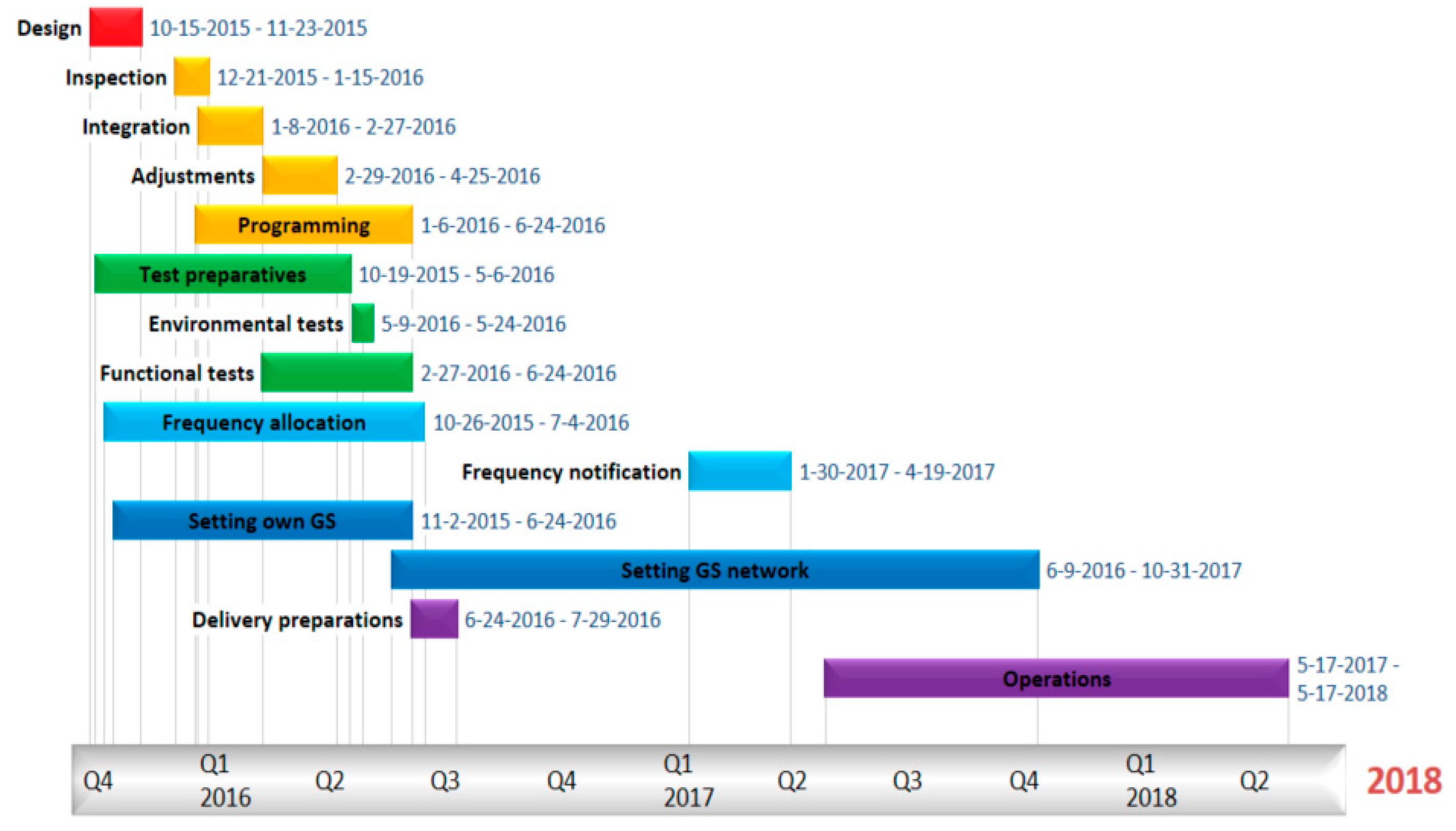
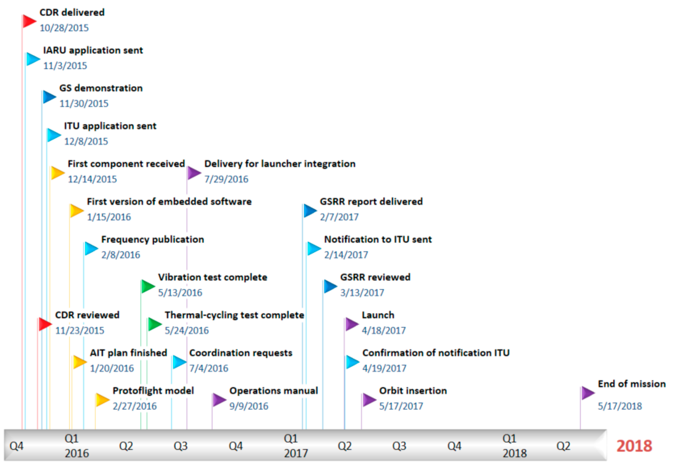
In order to deliver the satellite on time for launcher integration, it is crucial to define a detailed work plan, and control the time spent on every phase of the mission. As an example, Figure 1 summarizes the timeline for the complete SE01 mission, and Figure 2 shows the most important milestones that were completed during the mission.
A preliminary design should be completed without full knowledge of all parameters, since external factors have an influence on the project. For example, the frequency allocation process, which often involves a lengthy formal procedure, may affect the communications subsystem. This is the reason it is important to work on the design of the satellite, the test campaign, the frequency allocation and the ground station in parallel right from the beginning of the project.
The inspection of components can start as soon as they arrive at the laboratory. Once the structural components are inspected, the integration of the satellite can begin without the need to inspect all components. The satellite may need additional adjustments to meet unexpected requirements or deviations from the design.
It is possible to start programming the satellite at the beginning of the project. However, some software developing practices, such as Test-driven Development (TDD), recommend testing the software while it is being developed [30]. Therefore, in practice, software should be directly programmed on the target computer.
Preparations for the test campaign consist of defining the tests, designing fixtures, and finding laboratory facilities that can perform the tests according to the specifications. The pure test campaign can be done in two weeks. However, functional tests are performed every time a new version of the software is developed, and thus may take a longer time.
Setting up a ground station for the mission may take as much time as for making a satellite ready for launch. Furthermore, having one ground station does not guarantee reliable and consistent access to the satellite once it is in orbit. Opportunities for communication in LEO are scarce, with up to five contacts per day of less than 12 min. The viable approach to maximizing communication time with the satellite is to increase the number of ground stations used for the mission by creating a network of ground stations. Finding interested institutions and coordinating them is often a long-term initiative, which may take more time (and effort) than one CubeSat mission.
2.3. Satellite Registration and Frequency Allocation
Whether the developers have a ground station or they are going to assign the telecommunications to a satellite operations contractor, there are two legal steps that need to be completed, i.e., the satellite registration and frequency allocation. Both steps should start as soon as the team begins working on the project, because the process can take several months. In particular, frequency allocation has an impact on both the mission design and final tuning of components.
If the CubeSat is going to operate with a commercial telecommunication frequency, both requests are handled via the International Telecommunication Union (ITU) [31]. However, most CubeSats operate with radio amateur frequencies, because they are free of charge. In that case, the frequency allocation should be handled through the International Amateur Radio Union (IARU) [32], though the satellite registration is still handled by the ITU. Deciding in which band the satellite should operate basically depends on the purpose of the mission. Typically, CubeSats operate in very high frequency (VHF), ultra high frequency (UHF) or S-band. It should be noted that in order to use amateur frequencies the channel should be open to the public. This requirement can be problematic if it is intended to retrieve confidential telemetry from the satellite, but most scientific and educational missions should not be concerned about this requirement. In any case, there must be at least one liable person for each ground station as well as the CubeSat. In the specific case of using radio amateur frequencies, the person must hold a radio amateur license. Getting a license as an amateur radio operator may take a few months until the candidate passes the corresponding exam. Hence, a quick shortcut for the project would be to find a licensed operator who can help the team with this matter from the beginning. The radio amateur community is quite popular and open to collaboration with the space community. An example of such collaborative spirit from the amateur community is the Satellite Networked Open Ground Station (SatNOGS) project. Such a project consists of a network of ground stations run by volunteers with the aim of observing LEO satellites and capturing their downlink telemetry. The SatNOGS network is accessible through Reference [33].
The CubeSat registration process starts by contacting the local (national) telecommunication authorities to communicate with them your intentions of registering a new satellite. They will manage the application before the ITU. It should be noted that the ITU work at a diplomatic level, and they cannot be approached unless through the recognized authorities. The first documentation to be prepared is a letter of application. Together with the letter, there should be another document with the information described in the Appendix 4 of the ITU Radio Regulations. Such a document consists of a collection of database files that are generated by a dedicated software, SpaceCap, and verified by another software, SpaceVal. Both software applications are provided by the ITU. These database files contain information such as orbital parameters, frequency bands, link budget, geographical data and antenna diagrams. Some additional information may also be requested by the local authorities, such as purpose of the project, duration of the mission, and equipment description.
For the amateur frequency allocation, the IARU requires an Amateur Satellite Frequency Coordination Request form. The information that needs to be provided in this form is similar to the one provided to the ITU for satellite registration, but in the format of a written report.
If the applications are successful, the IARU will publish the allocated frequency in the list of satellites whose frequencies have been coordinated within a month or so. The satellite registration will be confirmed and published by the ITU through the Space International Frequency Information Circular (IFIC) in less than three months. During the following months the development team should expect to receive formal letters of “request for coordination” from international telecommunication authorities. These requests must be replied with formal letters, which are again handled by the local (national) authorities.
Finally, in case of using amateur frequency range for the CubeSat, the development team must notify the IARU with the allocated frequency no earlier than six months after the publication of the pertinent case in the IFIC. The notification process is similar to the satellite registration process, but the forms must be filled with the definitive and accurate data.
2.4. Quality Assurance and Documentation
Quality Assurance (QA) is the set of measures oriented to make sure that the work done during the project is conducted consistently and according to the stakeholders’ expectations. The standard defines the workmanship, processes and materials used during the project as well as the procedures and means of check the activities throughout the project. Additionally, QA allocates a contingency plan to manage any deviation from the original plan.
ESA’s standard on Quality Assurance [34] for satellites focuses on certain activities that will ensure the quality of the design and development process, but does not specify how to perform such activities. The activities can be categorized in eight general principles, i.e., controlling critical items, controlling nonconformance, managing alerts, establishing the means of proving acceptance authority, tracing parts and responsibilities, controlling metrology and calibration procedures, establishing measures on handling, storage and preservation of components, and defining statistical quality control procedures for batch production.
Documentation plays a crucial role in performing QA as well as maintaining (and disseminating) the knowledge constructed throughout a project. It is also an effective way to keep track of poor practices or mistakes done during the development process. ESA’s standard on Quality Assurance requires preparing an extensive set of documentation for every space project. However, some interpretations of such standards may lead a team to produce redundant documentation. Redundancy in documentation can not only reduce the efficiency by causing extra work of creating repetitive documents, but also cause confusion due to version mismatch. Therefore, care must be taken to avoid unnecessary redundancy and to update all sources of information when introducing changes into the documentation.
The ESA’s standard is mainly tailored to conventional space missions, due to their advanced complexity and high costs and associated risks. Nevertheless, even partial implementation of the standard can have a significant impact on improving the success rate of CubeSat missions, thus enhancing the chance of continuing CubeSat programs within small institutions. However, the application of such a standard could entail notable amounts of documentation that may end up challenging for some (small) CubeSat teams. To address this problem, ESA is currently working on the simplification of the QA requirements and documentation for CubeSats missions. Examples of some recent works are mentioned in References [35,36].
2.5. General Facilities
To conduct a CubeSat mission, the development team requires a different set of facilities for each phase of the project, i.e., fabrication, assembly, integration, test, and operation. A workshop with a milling machine, drills, saws, and other power tools is suitable for the fabrication of simple structural parts and making small modification to the existing ones. Additionally, a computer numerical control (CNC) machine may provide the development team with some manufacturing autonomy at the cost of having qualified personnel. An additive manufacturing machine may also increase the efficiency of the development team for rapid prototyping purposes or fabricating some supporting components. A soldering station equipped with, lenses, irons, a stable bench, and an extractor for the fumes is crucial to make quality electronic board assemblies and fabricate cable harnesses.
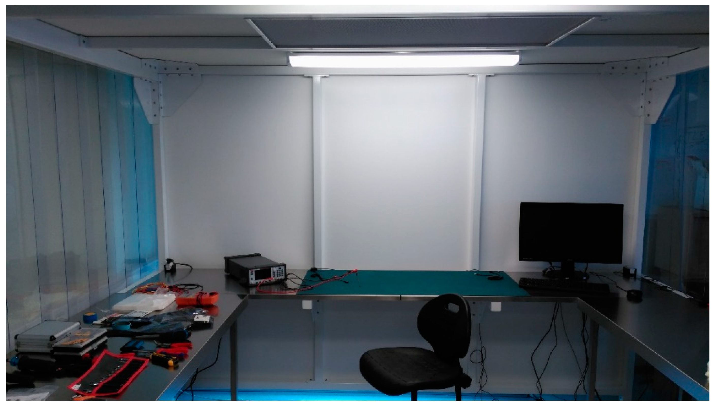
Once all components are built either in-house or outsourced, they must be cleaned, inspected, and integrated together in a controlled environment, to pass the cleanliness requirements. For CubeSats, such requirements usually restrict the manipulation of the flight unit in a cleanroom of FED_STD-209E class 10,000. Such class number refers to the maximum amount of particles with a size of 0.5 µm or larger that are allowed in a cubic foot of air. Although the FED_STD-209E classification is still commonly used among CubeSat developers, the standard has been superseded by the ISO 14644–1 standard [37]. A FED_STD-209E class 10,000 is equivalent to a class ISO 7. It should be noted that, in order to minimize the amount of suspended particles in the cleanroom environment, it is required that the operators wear lint-free coats, head covers, masks, shoe covers, and gloves. Additionally, the cleanroom must be equipped with tools for integrating electronic components, such as properly grounded anti-electrostatic-discharge mats and wristbands (Figure 3). The cleanroom also requires instrument to perform electric and functional tests, including a computer, multimeter, function generator, power supply, and oscilloscope.
Most functional tests can be performed in a cleanroom. However, qualification tests must be performed at sites with specialized facilities that may be expensive to own and operate, such as electric shaker and thermal-vacuum chamber. More details on such equipment are provided in the Verification and Validation section.
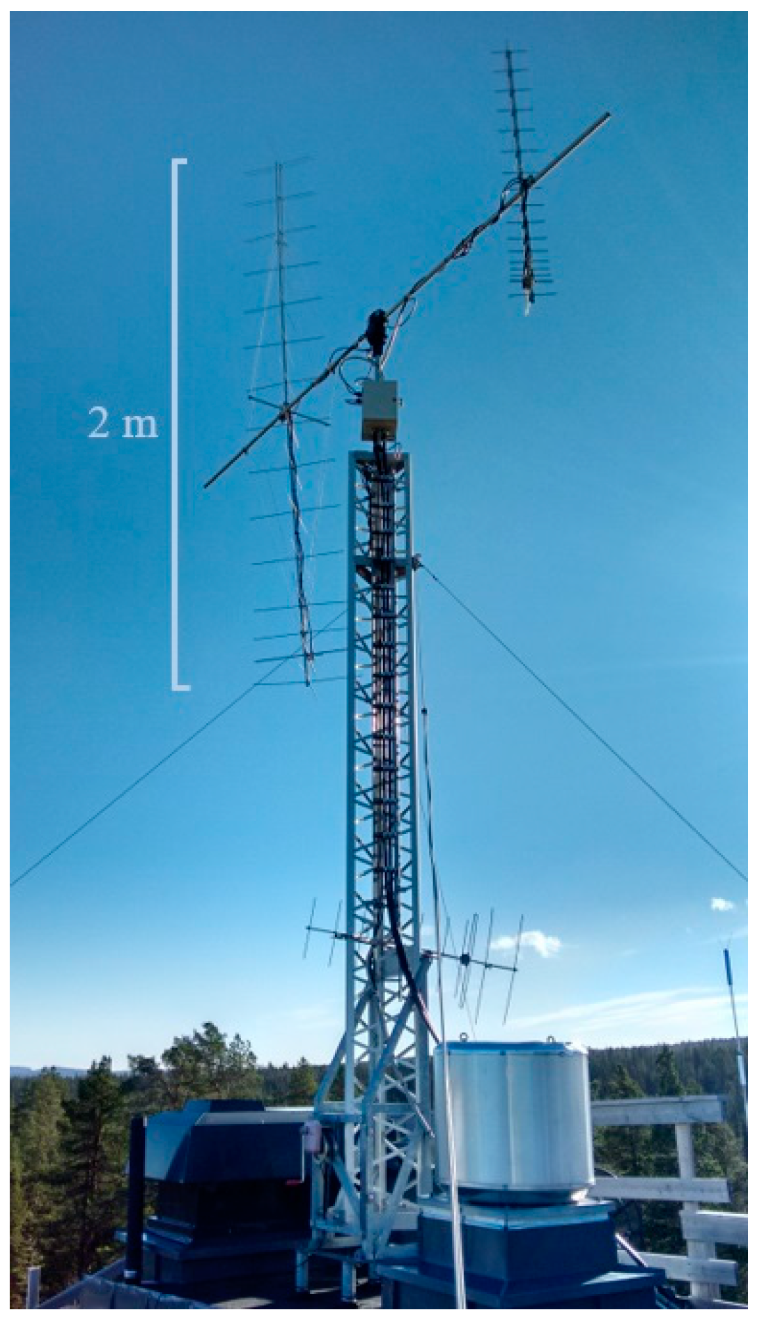
Finally, the mission relies on having at least one ground station to communicate with the CubeSat. A ground station suitable for a CubeSat mission usually operates in the VHF and UHF bands, i.e., 144–146 MHz and 435–438 MHz for the amateur region 1. Missions that require a wider bandwidth to download science data may also operate in the S-band, between 2.40 and 2.45 GHz in the amateur band. It should be noted that to improve the gain of the ground station, directional antennas should be used together with a pointing mechanism. Such antennas need to be installed in an open spacious area, typically a rooftop (Figure 4).
The length of a Yagi antenna for the VHF band is 2 m, and 70 cm for a UHF antenna. Antennas operating in the S-band are more effectively designed with a dish or patch shape. To amplify the signal modulated by a radio transceiver, a low-noise amplifier (LNA) with a power output between 10 W and 100 W is sufficient for LEO missions. Additionally, a computer is necessary as the operator’s interface as well as for generating command signals, tracking the satellite, tuning the transceiver, controlling the power output, pointing the antennas, etc.
3. Fabrication and Integration
One of the incentives behind CubeSats is maximizing the commercial off-the-shelf (COTS) components that can be used to build the satellite. This means that ideally developers of a CubeSat are to fabricate minimum possible amount of parts. This idea is supported by assuming that some parts of sufficient quality can be obtained at costs less that their in-house fabricated counterparts, even if those COTS components are not space qualified.
In this sense, there have been serious attempts to catalog state-of-the-art CubeSat components [38], and report the expected evolution of technology applicable to CubeSats [39]. The selection criteria for such COTS components should rely on flight heritage and the results of a thorough verification and validation process. Regarding the first factor, the more flight hours that a component can demonstrate without a failure, the more reliable it is. Component suppliers do not usually provide detailed reliability statistics, but they do provide the number of successful missions. Such a number can be used as a proxy figure to the reliability of the component, especially considering the high rate of CubeSat infant mortality. A statistical analysis and a reliability estimation model for CubeSats are discussed in Reference [40]. With respect to the second factor, the development teams may increase the reliability of the components by testing them in an appropriate environment at early stages of the development process. For this purpose, the utilization of hardware-in-the-loop simulation techniques for nanosatellites is proposed in References [41,42]. In such simulations, prototyped components can be integrated with other emulated components, and tested against their specifications through fault injection. In the later stages, a fully integrated system can also be validated in a similar manner.
The following sections describe the development of SE01 as a reference for guiding prospective developers toward the most common materials, components and practices for fabrication and integration of CubeSats. For more detailed investigations, ESA has published a database with material specifications for outgassing, corrosion, flammability, etc. [43]. NASA has also made available a database with the results of outgassing experiments [44].
3.1. System Layout
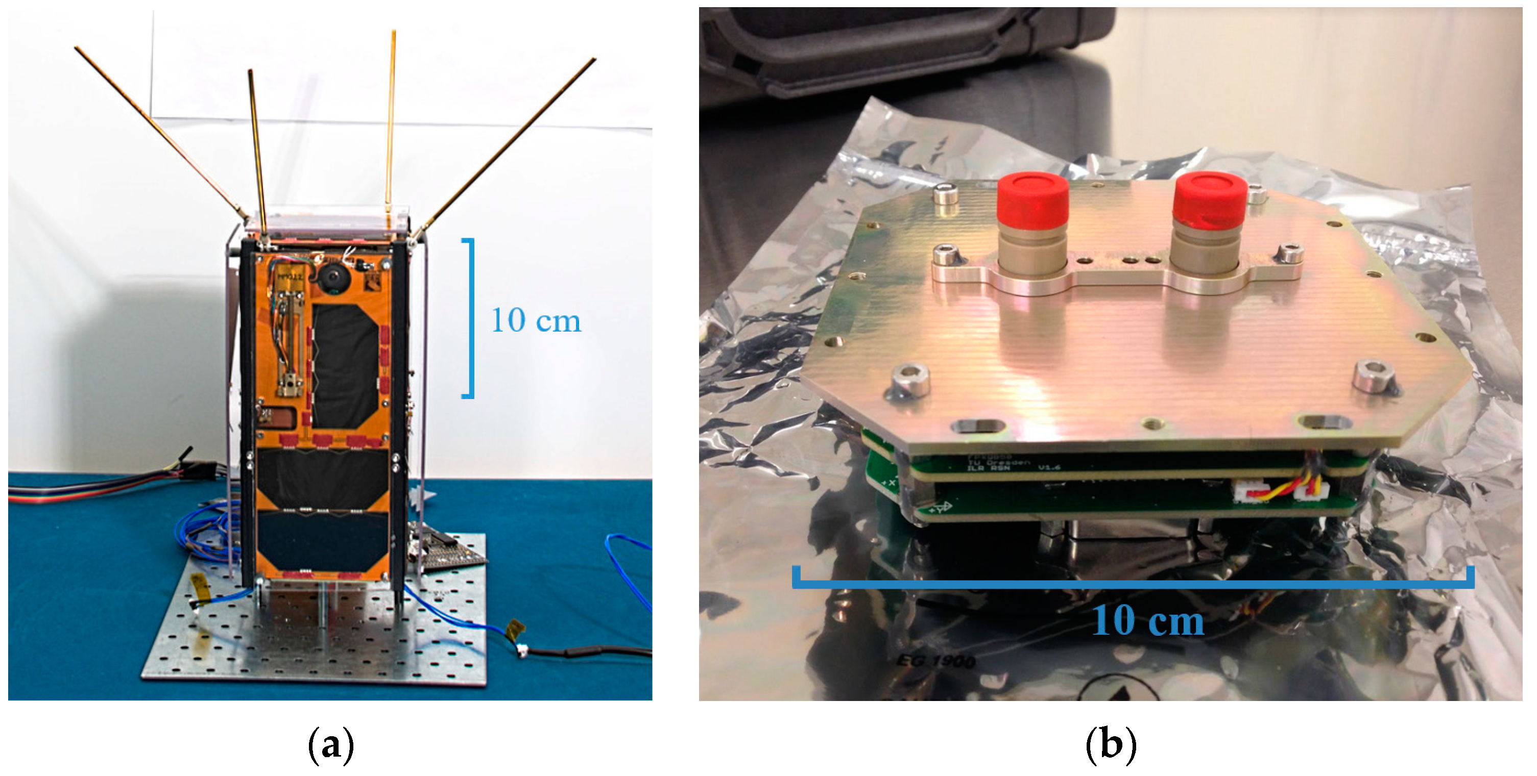
The SE01 CubeSat has a two-unit (2U) form factor, as shown in Figure 5a. A single-unit CubeSat has a dimension of 10 × 10 × 10 cm3. The satellite has 17 solar cells that are mounted on all the external sides, expect for one side (the bottom in Figure 5a) which is used for the science payloads.
The SE01 CubeSat has two payloads. The primary payload is FIPEX, which has been developed by the Technische Universität Dresden in Germany. The payload measures the time-resolved flux of atomic and molecular oxygen using two sensors that are exposed to the space environment (see Figure 5b). Following the CubeSat Specifications [45], the payload is mounted at the bottom side of the SE01 CubeSat, since this is the only side with allocated space for protruding elements before the CubeSat’s release into the orbit. The secondary payload is an onboard computer developed by LTU’s project partner, Open Cosmos Ltd., for its in-orbit demonstration; hence its name Open Cosmos’s Onboard Computer (OC-OBC). The secondary payload is positioned inside the SE01’s structure with the rest of electronics.
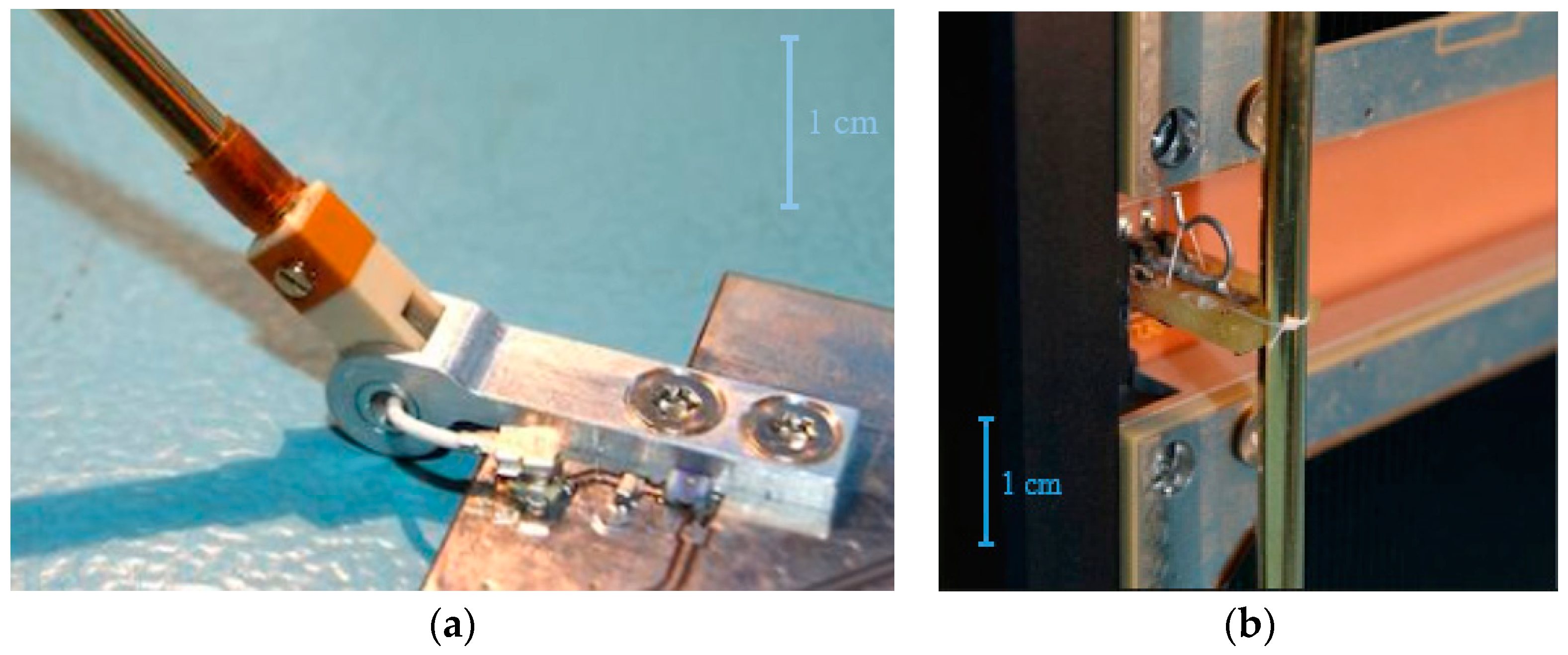
Additionally, the satellite’s attitude determination and control system (ADCS) relies on an external magnetometer module, which is also mounted on one of the sides (front in Figure 5). On the top side (opposite to the payload side) the antenna unit is mounted next to two solar cells, which includes four hinged monopoles that can be stowed vertically within the CubeSat envelope. A detail view of an antenna hinge can be seen in Figure 6a. Antenna monopoles are kept stowed through four inter-stage units, as illustrated in Figure 6b. Such inter-stage units are located in the space between the two stacks of electronics inside the satellite. The inter-stage units also serve as an interface with the ground support equipment.
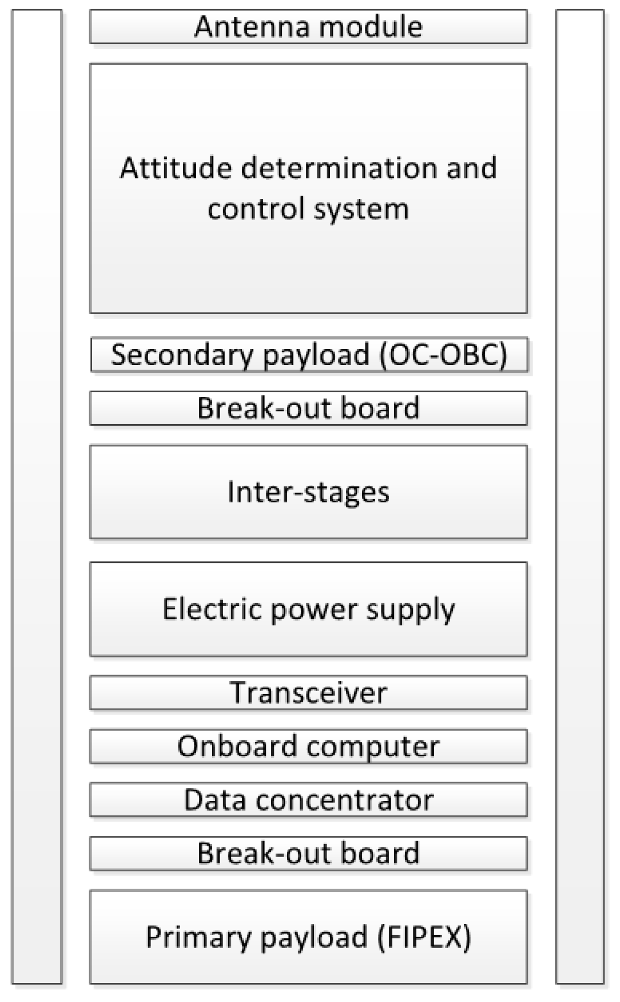
The distribution of subsystems in a CubeSat is highly dependent on the requirements for every mission. In general, in addition to the antennas, solar panels and other external appendages, the typical configuration of a CubeSat should also include at least one payload (PL), a data concentrator (DCU), an onboard computer (OBC), a transceiver (TRX), an electric power supply (EPS), and an attitude determination and control system (ADCS). The break-out boards are used to connect the bus to any component that needs dedicated harnessing, and to provide bus continuity between different electronic stacks. The physical placement of subsystems within the CubeSat depends on the available space within each electronic stack and the particular constraints that each subsystem may have, such as the ones for the FIPEX payload. The final configuration for the SE01 CubeSat is shown in Figure 7.
3.2. Structure
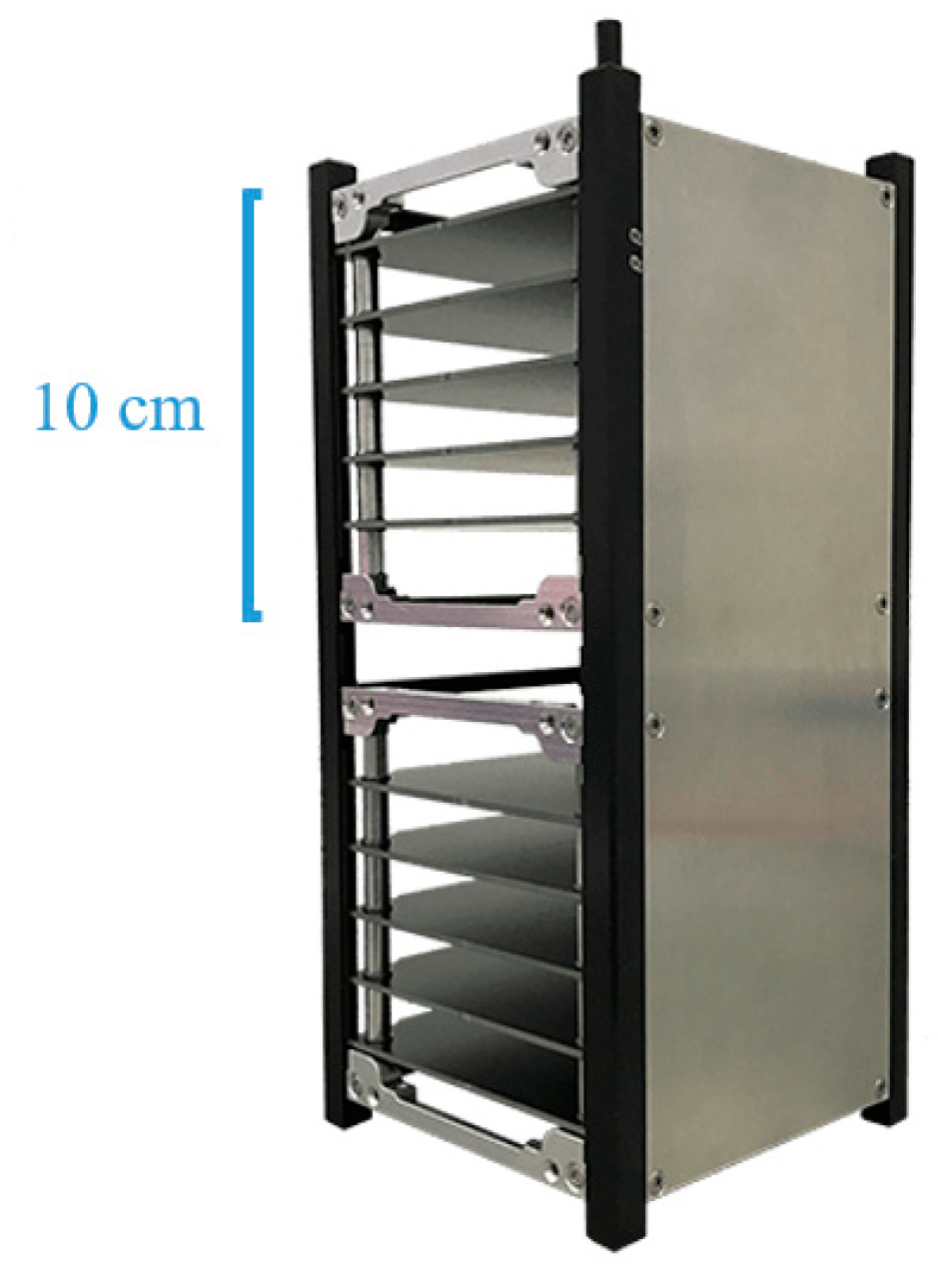
The adopted structures for CubeSat designs have become quite mature in recent years. However, they inherit a fixed construction approach from the early CubeSat missions, where all subsystem boards have a unique way of being stacked. Figure 8 illustrates such a configuration for a 2U CubeSat structure. The materials used for structural purposes are basically aluminum alloys for aeronautical applications, 7075 and 6061, as well as austenitic stainless steel, A2 and A4. However, aluminum materials must be surface-treated with a hard anodize coating, which is non-conductive, in order to prevent cold welding and corrosion. If conductive surfaces are required, aluminum should be treated with chromate conversion coating. Moreover, the use of steel in CubeSats is restricted only to fasteners or mechanical parts, to avoid magnetic field disturbances.
3.3. Bonding Materials
Outgassing is a frequent problem that affects most of bonding materials. There are three major bonding materials that are suitable for CubeSat assembly. Epoxy can be utilized when a hard and lasting bond is required, e.g., to secure fasteners, to encapsulate electronics, and as strain relief for electric wires. Epoxy has a prolonged curing time that typically lasts one hour or more depending on the composition and the catalyst dose. Further, room-temperature vulcanizing (RTV) silicone can be used in CubeSats as a filling, and to consolidate harnessing or any other appendages. After the silicone is cured, it is easy to remove by hand, but it is commonly used as a permanent bond for light components. The curing time takes a few minutes, so it is more suitable as a quick adhesive solution than epoxy. Additionally, Kapton tape can be used to make labels, secure a beam of wires, routing harness, hold components that do not need a strong and permanent bond or even protect surfaces from scratches. The adhesive is very sticky and problematic to handle, but it does not leave any residue when removed from surfaces. In general, it is not convenient to overuse bonding materials, because they can change significantly the inertial properties of the satellite.
3.4. Electronics and Connectivity
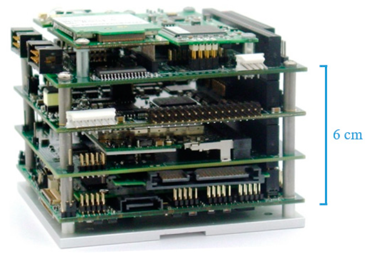
The CubeSat industry has adopted the PC/104 specifications [47] as a de facto standard for the electronic boards. Moreover, such specifications provide mechanical and electrical benefits towards CubeSat fabrication beyond the compatibility with different structure and electronics suppliers. Following the PC/104 specifications, all electronic boards must measure 3.550 × 3.775 in2 (90 × 96 mm2), and the electric bus must allocate four rows with 26 contacts of standard 0.1 inch spacing through-hole (THT) headers. Additionally, all necessary boards can be stacked in modules, as illustrated in Figure 9, whose maximum volume must be able to fit in a 1U CubeSat form factor. Such electronic boards can be firmly attached together with M3 standoffs, and they share the same bus connection throughout the stack, thus improving the stiffness provided by the CubeSat’s structure and simplifying the internal harnessing.
Printed circuit boards (PCBs) are fabricated with a succession of layers of FR-4 reinforced glass fiber and copper. The standard process for PCB production can be adopted for space purposes. However, some coating materials used during PCB fabrication may not be suitable for in-orbit utilizations, due to outgassing issues. For the same reason, care should be taken for the selection of soldering mask or silkscreen products. In case of doubt, such products should be avoided for qualification or flight units. However, it is recommended that a layer of space-proof conformal coating be applied to the board after all components have been soldered, to protect electronics from environmental interaction.
Some metals are susceptible to outgassing and whisker growing. Whiskers are thin metal crystals that grow under vacuum conditions and may produce short circuits between electric contacts. The list of materials to avoid includes brass, zinc and cadmium [48]. To avoid whisker growing, soft solder alloys with at least 40% of lead content are commonly used. However, silver alloys are preferred, such as 95Sn-5Ag, due to its low toxicity compared to lead alloys.
A fully integrated satellite can have hundreds of wires densely packed between electronic boards. The complexity of routing the harness grows exponentially with the number of wires. For this reason, it is important to simplify the mapping and minimize the number of wires. Using color-coded wires and labeling both ends of a harness may help identifying the origin of used connections. Moreover, the material of choice for wire insulation and shrinking tube should be polytetrafluoroethylene (PTFE) or polyolefin (PO), but polyvinyl chloride (PVC) should be avoided for these cases.
When the umbilical interface provided by a CubeSat supplier does not cover all the required lines, the developers need to improvise additional external harnessing. This situation is not desirable, because the satellite may end up with several connectors hanging around. Ideally, if the umbilical harness cannot be handled by a single interface, all connectors should be close to each other on the same board.
The miniaturization of components in a CubeSat also leads to the use of minimalistic connectors for ad hoc applications. Although these connectors can be found made of high-quality polymers, they tend to break either through the locking tabs or the wire junctions. They are especially sensitive to decoupling cycles. Developers sometimes need to use tweezers to handle the connectors; consequently, connectors can be damaged more easily.
The electric power supply takes care of collecting, storing and distributing electricity to the rest of the subsystems in the satellite. A power budget analysis is necessary to study the feasibility of the mission and to size the components in the power supply chain. The power budget of the SE01’s mission is summarized in Table 2. First, the power consumption required by every subsystem is gathered. The required peak load is also relevant to sizing the capacitors that fulfill exceptional power demands during transitions. The overall nominal power requirement is calculated based on the duty cycle of every subsystem for the worst-case operational mode. The duty cycle is the average time period in which a specific subsystem is consuming power.
The average power generated by the SE01’s solar panels in the worst case is 2600 mW. Solar panels can sustain power for the satellite in a sun-synchronous orbit during the 42-min period in which the satellite is illuminated by the Sun [49]. The included Lithium-Polymer (LiPo) batteries of the SE01 CubeSat have to take over during eclipse. The typical voltage of the battery pack is 7.4 V, and it has a capacity of 2600 mAh. The battery level is self-sustained during control mode for the presented power budget. However, science modes will rapidly drain out the batteries. Hence, after every complete orbit running one of the science modes, the satellite should switch to low power mode to recover the battery level for safe operations.
3.5. Telecommunications
The different modulation schemes, emission patterns, data rates, the dynamics of the satellite and other minor parameters have an effect on the probability of completing the communications link between the CubeSat and the ground station. The link budget for the SE01’s mission is summarized in Table 3.
The SE01 CubeSat was equipped with a rigid canted turnstile antenna, as shown in Figure 5 and Figure 6. Such antenna was tuned to the UHF frequency band, particularly to 435.8 MHz. The stiffness of such kind of antennas provides a very stable omnidirectional radiation pattern. However, rigid antennas occupy a significant space on the side panels of the satellite when they are stowed. The performance of such antennas is significantly reduced if the radiating elements have to be shortened from its tuned length. Therefore, such antennas are not suitable for CubeSats smaller than 2U; otherwise, the antennas would trespass the limits of the allowed envelope in its optimal length. For the VHF frequency band, the required space for the antenna should be even larger.
Other kinds of antennas are also common for CubeSat missions. For example, 3Cat-1 was equipped with two bi-stable metal dipoles [17]. This kind of antenna can be quite simple and reliable, and operate in either VHF or UHF bands. However, such antennas are usually coiled around the satellite in the stowed position, taking space from the CubeSat’s side panels. Another example of antennas for CubeSats which can operate in the VHF and UHF bands are flexible coiled metal antennas, such as those used in Swisscube [24]. They take minimal space within the satellite structure while stowed, but once deployed they may not keep the optimal shape.
New missions with ambitious imaging objectives require higher data rates that neither VHF nor UHF bands can provide. The current trend in CubeSats is moving toward S-band frequencies, around 2.3 GHz. Operating in the S-band requires antenna topologies with directional radiation patterns. This can be provided by patch antennas, such as the one used for INSPIRESAT-1 [50]. Patch antennas are monolithic, taking small space fitting in a flat surface of 10 × 10 cm2, and may provide a gain of 6 dBi and an opening angle of 85°.
Currently, most common onboard radio systems are hardware-defined. However, the trend is moving toward software-defined radio (SDR), as it is the case for the SE01’s mission [51]. The SDR equipment has the benefit of being able to develop different radio designs with a single hardware implementation, hence not compromising the design of the telecommunications subsystem at the early stages of the project. Further, SDR also has the advantage of allowing the developer to bypass certain processing blocks, in order to simulate the signal at different stages. This is particularly useful to test the radio equipment and emulate wireless communications without actually powering the aerials.
4. Verification and Validation
The test campaign is an important milestone, because it confirms whether the project can move forward or developers still need to perform modifications to the satellite. For the SE01 CubeSat, the reference document that was used to design the test campaign was the QB50 requirements document [30]. Additionally, NASA provides guidelines on mechanical tests for its launch services program, which can be used as support reference [52].
4.1. Functional Tests
During functional tests the satellite is checked against its software behavior to see if the satellite is able to perform all programmed tasks successfully. Particularly, functional tests focus on the basic tasks that guarantee the satellite’s survival, such as communications, power distribution, and fault management. However, there are many other tasks, including orbit positioning and attitude control, which can hardly be quantified or even tested, because there is no suitable environment to perfectly emulate space conditions on Earth. Ideally, the satellite should have a complete verification of orbit operations. A hardware-in-the-loop simulation platform can emulate both virtual and physical in-orbit conditions, and can expand the currently available set of simulation scenarios.
Functional tests are performed before and after every major test, in order to check the evolution of the satellite during the test campaign. If an anomaly is found during a functional test, the campaign must be stopped until engineers figure out the cause and fix the problem. Some tests may need to be repeated to check for the full functionality.
4.2. Mechanical Tests
It takes several weeks to design and manufacture fixtures. Ideally, developers should start working on the test preparations in parallel to the fabrication of the satellite. Even if test campaigns can be outsourced, developers may still need to provide auxiliary equipment.
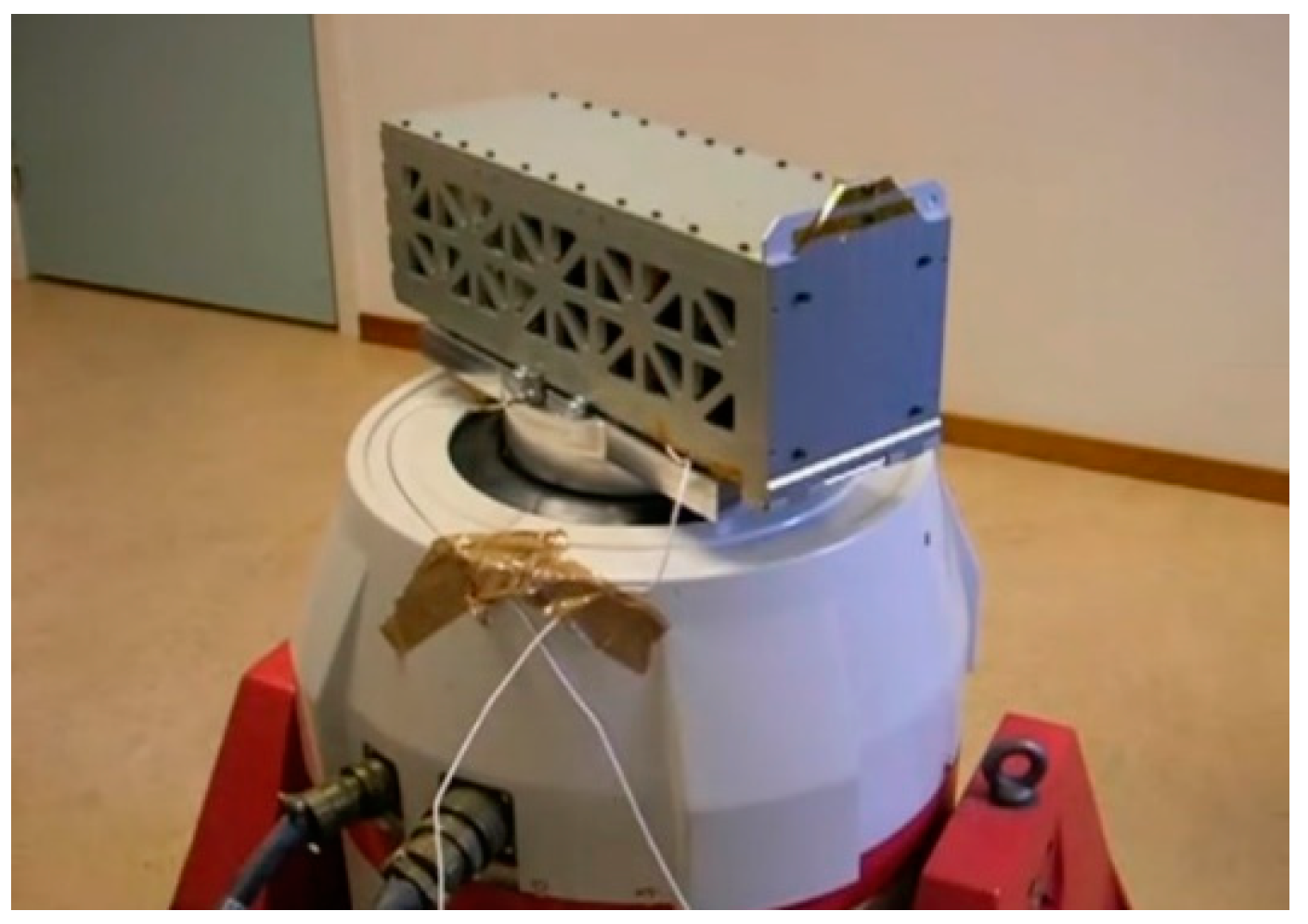
Major mechanical tests can be conducted with one electrodynamic shaker. Figure 10 shows the SE01 CubeSat in a 3U fixture mounted on a shaker through a head adaptor. Since a 3U fixture was available off-the-self, the developers decided to use the product instead of fabricating a 2U fixture in-house. A dummy payload was used to fill in the fixture along with the SE01 CubeSat.
Programming the shaker to follow all acceleration profiles may take at least one working day. Developers may need to make small modifications to those profiles during the tests, especially at both ends of the frequency range.
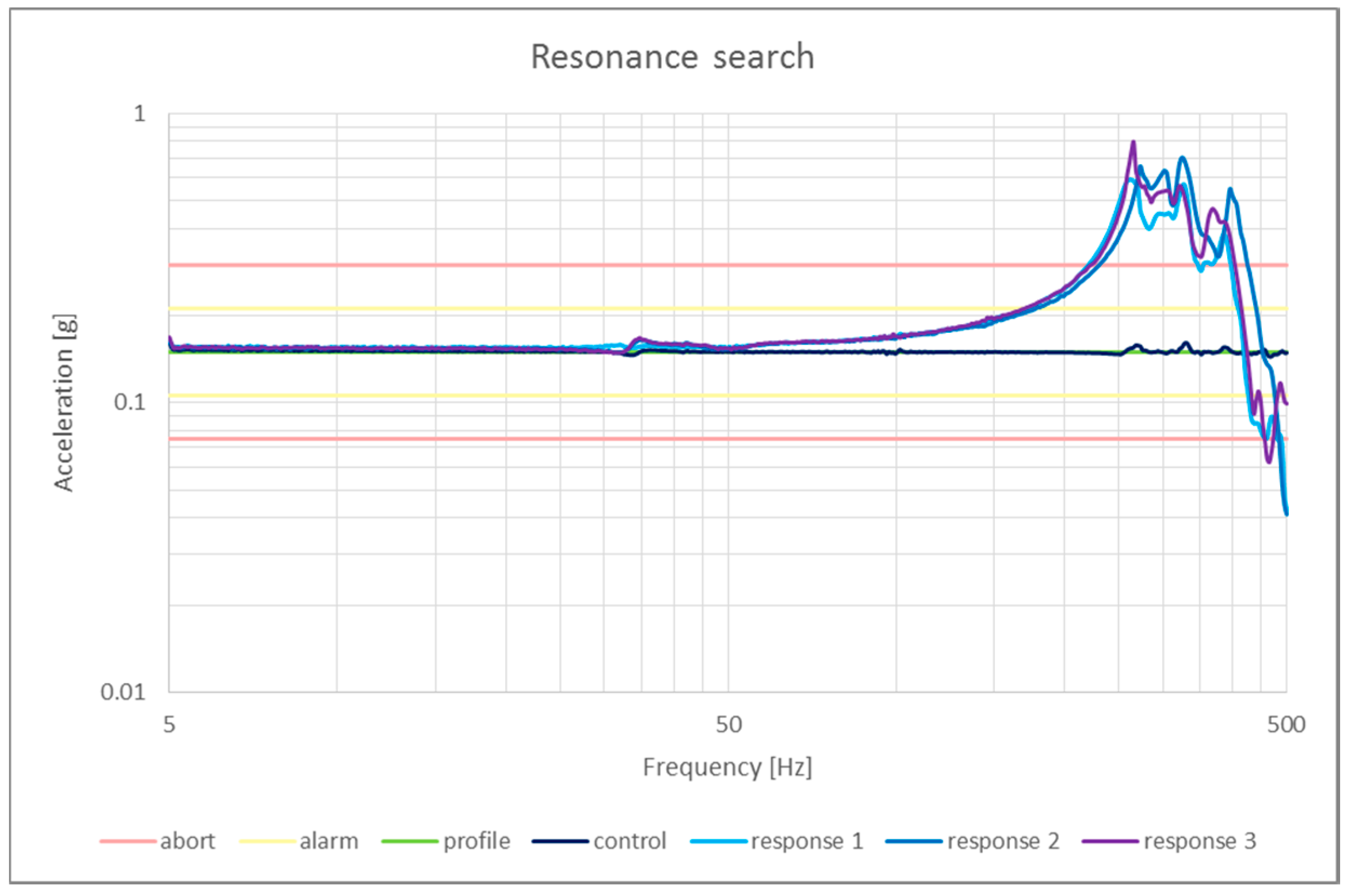
The resonance search test is used to find the lowest resonance frequency. Resonance search tests are performed before and after every major mechanical test. Figure 11 shows the response of a resonance search test for three runs and the control profile for comparison. For the QB50 mission, it was required that the first mode appears above 200 Hz. Additionally, the natural frequency for different runs should not shift more than 5%, otherwise it may indicate a failure during one of the major mechanical tests. On the positive side, a natural frequency shift may indicate internal readjustment, misalignment and/or interference with other components in the fixture. On the negative side, it may indicate loose components, unsecured fastening and/or broken parts.
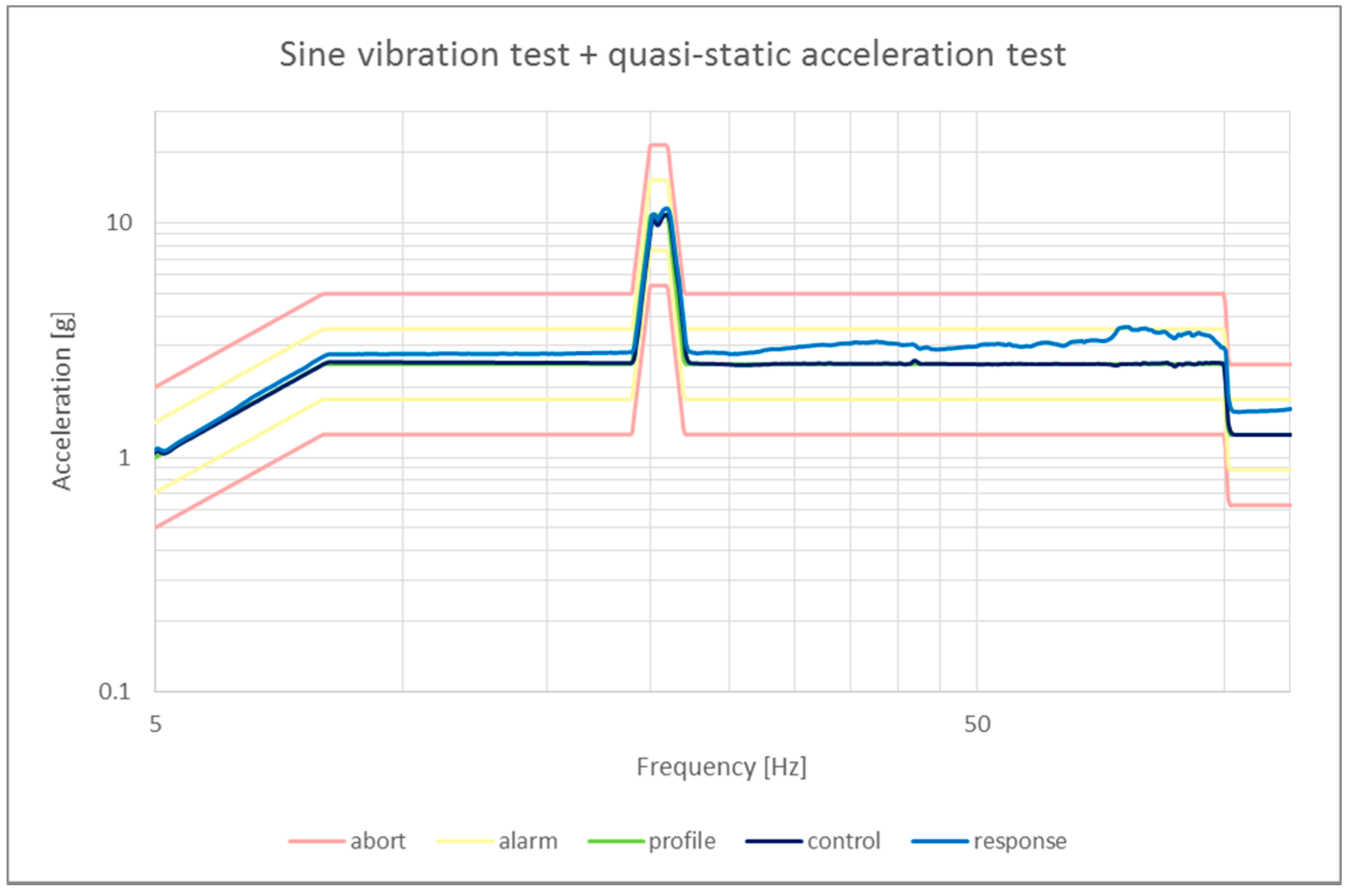
The sine vibration test is one of the major mechanical tests, which is performed to confirm that there are no dangerous resonance frequencies in the test range, and the satellite is able to withstand the required load. A quasi-static acceleration test (QAT) is also performed together with the sine vibration test. The QAT emulates the static loads of a rocket during the launch. Static accelerations are usually much higher than dynamic ones. To perform a QAT with an electrodynamic shaker, the acceleration profile should briefly increase to the required amplitude, and come down again for frequencies much lower than the natural frequency. For SE01 in particular, the amplitude of the control signal was increased to 10.8 g between 20 and 21 Hz during the frequency sweep. The results of a sine vibration test with QAT performed on one axis of SE01, shown in Figure 12, illustrate how the response of the satellite increases as it approaches the natural frequency. No unexpected acceleration peaks should be observed, and no damage on the satellite should be noted after the test.
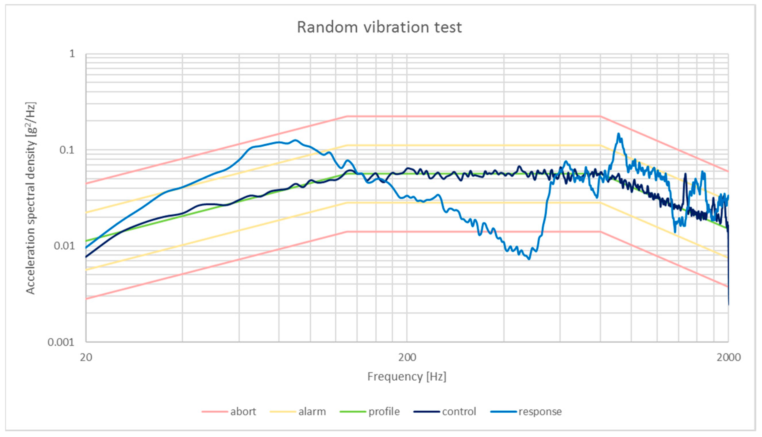
Random vibrations occur during the launch. Therefore, a random vibration test is used as an accelerated life testing. That is, higher load levels during the test correlate with longer operating times. In a random vibration test all frequency ranges are excited, thus all resonant frequencies are tested simultaneously. In case of SE01, a root-mean-square acceleration of 8.03 g was applied during 120 s for each axis. The results of random vibration test for one of the SE01 axes are shown in Figure 13. The actual root-mean-square acceleration experienced by the satellite was 9.30 g. No damage should be appreciated in the satellite afterwards.
Shock tests emulate rocket stage separation events. Typically, a shock test can be done on an electrodynamic shaker with a half-sine profile. The head of the shaker moves up and down only once in a period of tenths of milliseconds to achieve the required acceleration. Since SE01 was a proto-flight model, a waiver to skip the shock test was granted.
4.3. Thermal-Vacuum Tests
Thermal-vacuum tests check for the behavior of a satellite in an environment with different conditions of extreme temperature and vacuum. Such tests may take tens of hours to complete, and they require constant monitoring during temperature transitions. Assuming some breaks between the test for the team and for the analysis of interim results, the total time for performing thermal-vacuum tests may take at least one week to finalize.
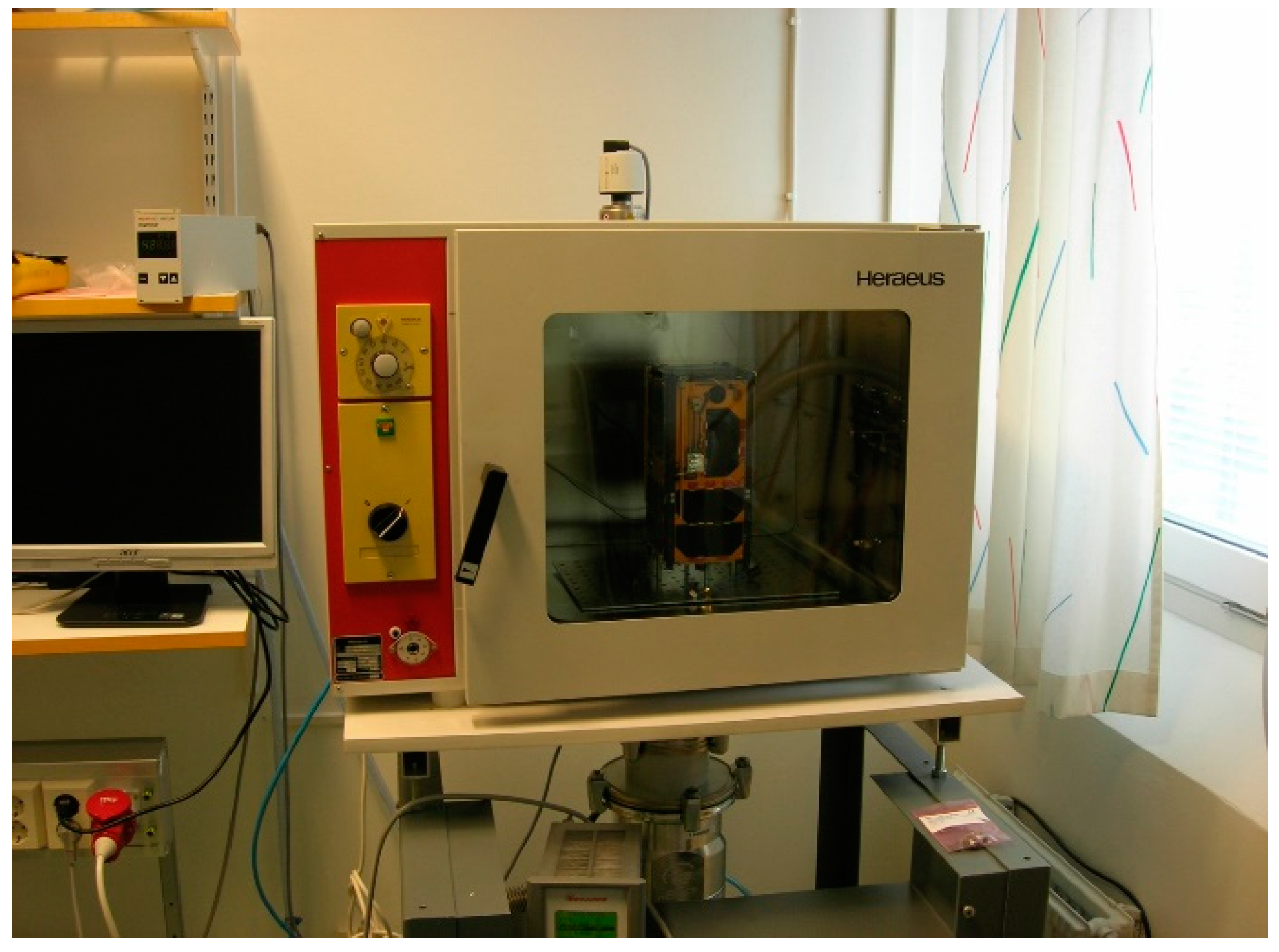
The purpose of thermal-vacuum bake-out (TVBO) test is to detect any anomalous behavior in the satellite exposed to high temperature and very low pressure. The TVBO test is commonly used for detecting outgassing materials in the satellite. The SE01 CubeSat remained for 3 h in a bake-out chamber (Figure 14), with a controlled environment at 50 °C and 1 × 10⁻⁵ mbar. During that time, the satellite only lost 2 g of its mass. Such a mass loss represents less than 1% of the total mass of the satellite, thus meeting the general requirements for outgassing.
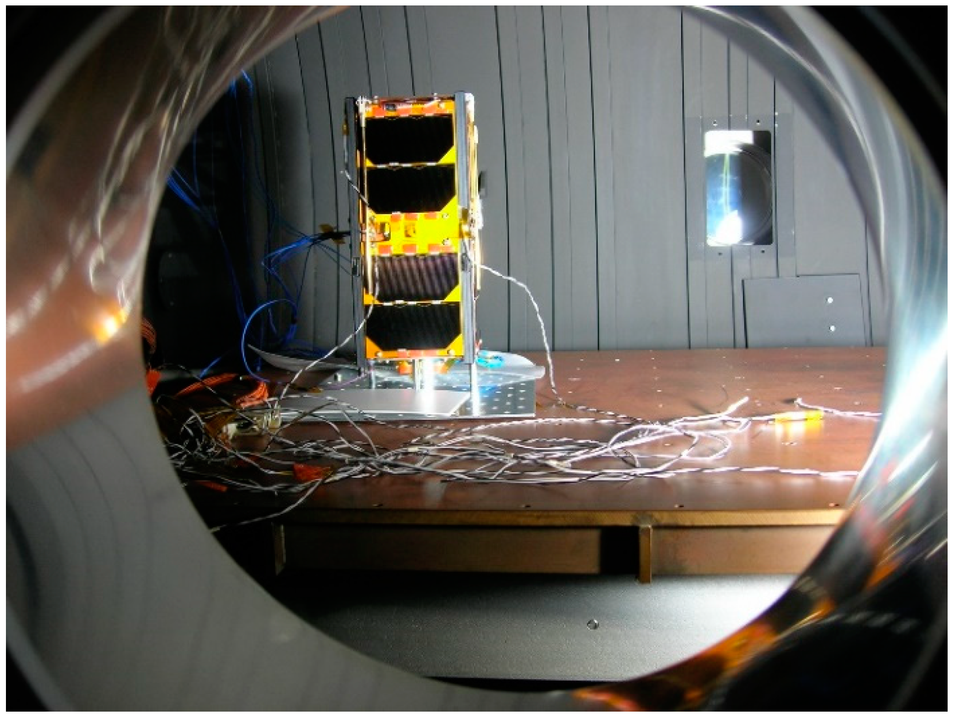
The satellite must also pass a thermal-vacuum cycling (TVC) test. Unlike TVBO, the TVC test is meant to check for how the satellite behaves under extreme temperature changes in vacuum. The environment to perform a TVC test must be prepared in order to reach both hot and cryogenic temperatures. Figure 15 shows the SE01 CubeSat inside a thermal-cycling chamber through an observation port during the TVC test.
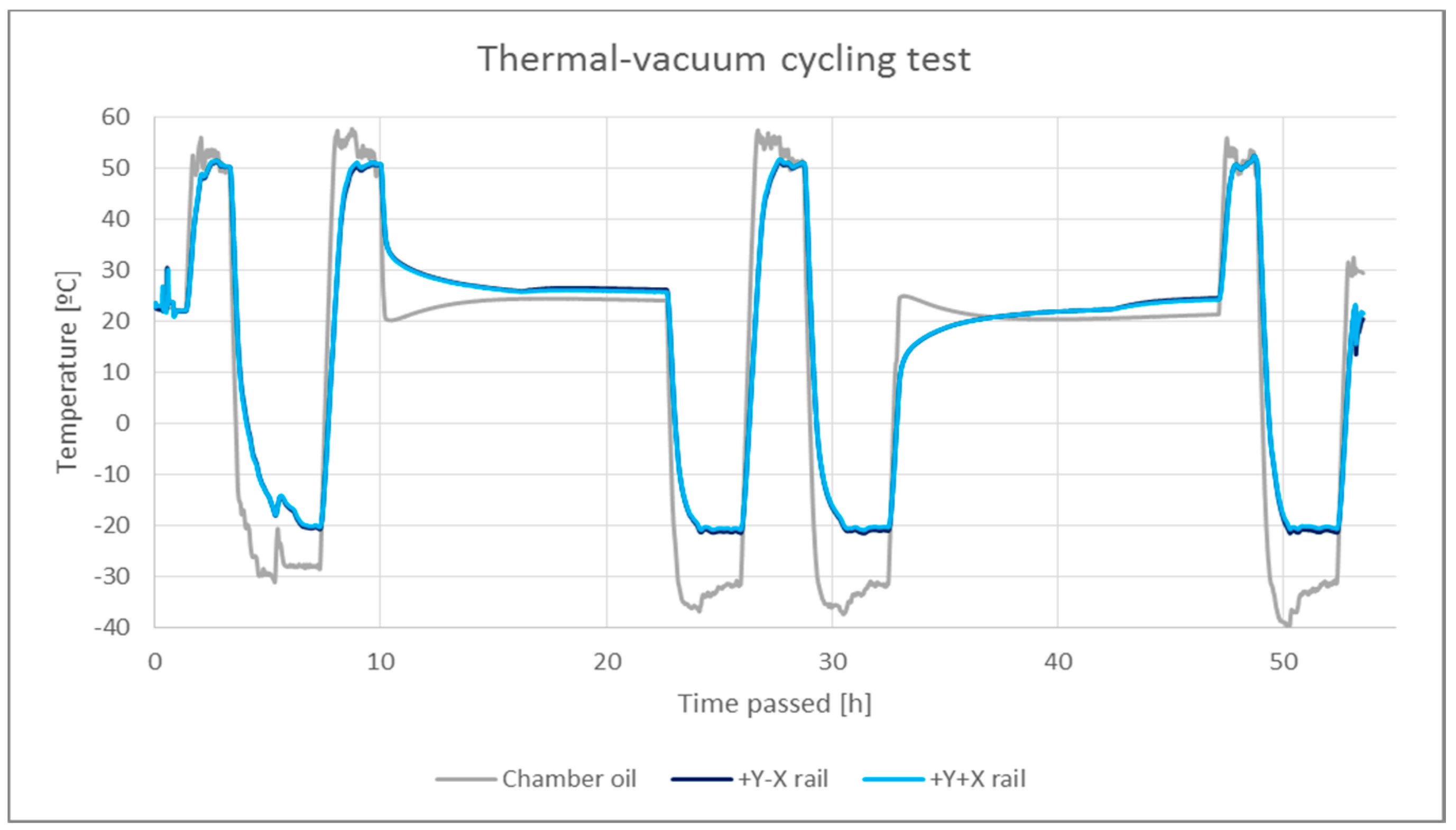
Following QB50 mission requirements, the satellites must pass four cycles with peak temperatures of +50 °C and −20 °C. A good grip between the CubeSat and the heating table leads to higher heat transfer to the satellite. Hence, a bolted union will make the temperature cycles much faster than placing the CubeSat resting over the table. Figure 16 illustrates the temperature profile of two different points of SE01 and a control temperature during the TVC test. Long periods of time occurred, during which temperature was kept constant at 25 °C, due to the unavailability of an operator for the chamber overnight. Additionally, the pressure was kept under 1 × 10⁻⁵ mbar during the entire test. Additionally, the TVC tests require performing functional tests during the one-hour-long plateaus at the highest and lowest temperatures. Hence, it is necessary to fabricate an umbilical cable especially designed to interface all needed satellite connectors through the vacuum chamber. It should be noted that both the materials used for building the satellite as well as the umbilical should have low outgassing properties. Vacuum chamber operators may require a detailed breakdown of all materials used. In conclusion, a TVC test is considered successful if all functional tests are passed and no damage is observed on the satellite after the test.
5. Delivery
After assembly and tests, the CubeSat needs to be packed properly and transported to the launch service provider. In general, the place where the satellite is assembled may not necessarily be close to the launch facilities. Satellites are usually taken to an intermediate location first for their final integration to the launcher interface before going to the launch facilities. Service providers take the responsibility of the satellite from the moment it enters their facilities to the orbit insertion, and they sometimes even offer support to developers during the delivery process.
5.1. Packing
The CubeSat has to be taken from the laboratory’s clean environment to another clean environment at the launch service provider’s site without being exposed to the dust. Hence, packing the satellite properly is crucial. A sealable antistatic bag to cover the entire satellite is usually sufficient. Vacuuming the bag may be preferred, although small amount of air inside the bag could act as cushion and protect the CubeSat against hard impacts.
In general, solar panels are very delicate to scratches, so ideally nothing should touch them during their entire lifetime. A common measure to avoid any accidental contact with the solar panels during ground operations are methacrylate covers. They are quite effective to protect solar panels, but they usually need designated points in the structure to attach to with the accompanying fasteners.
To transport the satellite safely a shock-absorbent suitcase is required, such as those used for transporting delicate instruments like optics and filming equipment. These suitcases usually come with shock absorbing foams inside, which protects the item from any impact. However, foam materials can be easily charged electrically, and they can also leave residues after trimming them to size, both of which may be detrimental to clean room operations. Additionally, tamper-evident seals, such as a simple signed zip tie, should be used to prevent the suitcase from being opened during transportation.
5.2. Transportation
It is necessary for the developers to understand the regulations enacted by national (and international) authorities regarding export of satellites. Some countries may even put in place special regulations for CubeSats. Within the European Union, CubeSat developers do not need to meet any special requirement. However, most typical launch sites for CubeSats are not located within the European Union, such as Cape Canaveral in the US or Baikonur in Kazakhstan. Consequently, an export license issued by the Customs Office may be required. One may also need to ensure that no international traffic in arms regulations (ITAR) apply to the CubeSat package through its route.
Standard shipping companies may not be sufficiently reliable for shipping CubeSats (from Europe,) since they do not seem to offer special services tailored to CubeSat packages, and they do not provide reasonable insurance for such parcels. Further, they do not assume any responsibility if the parcel is stopped at customs, and it will be very difficult to claim for any damage if something happens internally.
A viable option for the CubeSat transportation would be to deliver it to its destination in person. Nevertheless, travelers should make prior arrangements and be prepared during the trip with sufficient documentation, such as manuals, blueprints, export licenses and any other proof of shipment, in order to minimize difficulties with the customs and security checks.
6. Operations
The SE01 CubeSat was launched, together with other 27 QB50 satellites, on 18 April 2017, on an Atlas-V rocket as part of a resupply mission to the International Space Station (ISS). The remaining eight QB50 satellites were launched on 26 June of the same year to a polar orbit on an Indian Polar Satellite Launch Vehicle (PSLV). The SE01 CubeSat was deployed into orbit from the ISS on 17 May. From that moment the development team was granted a period of seven weeks to complete the launch and early operations (LEOP) phase for commissioning all subsystems and payloads.
The LEOP phase starts with the early discrimination phase that usually should not last more than one week to check whether the satellite survived the launch, and identify the satellite among all other satellites that may have been deployed simultaneously. Additional checks can be performed to find out whether all appendages have been deployed, and the solar panels supply enough power to operate the CubeSat. The North American Aerospace Defense Command (NORAD) is the organization responsible for tracking and cataloging all celestial bodies in orbit. The NORAD organization publishes a list of all civil satellites and their two-line element (TLE) sets, which can be accessed from Reference [53]. During the discrimination phase, NORAD publishes the TLEs of unrecognized satellites, which can be distinguished through the NORAD catalog number, e.g., 42708 or the Committee on Space Research (COSPAR) designator, e.g., 98067LR. The first orbital elements are published no more than 5 h after the CubeSat flies over NORAD’s radars. Discrimination occurs when operators can unambiguously identify their satellite as the body in the catalog with the orbital elements, in order to be able to successfully track and communicate with the satellite.
The LEOP phase continues with a platform commissioning and detumbling phase. In this phase, all subsystems of the CubeSat are checked for their correct function in orbit. Care should be taken to guarantee that satellite operations are not disrupted by the tests. Particularly, ADCS is a critical subsystem for the success of the mission, and is very sensitive to commissioning tests. The satellite may have some rotations induced by the deployment mechanism during orbit insertion. The CubeSat has to be detumbled to a stable attitude. Such detumbling operation is usually performed by magnetorquers. Once the satellite is stable, other actuators such as reaction wheels can take over for fine attitude control required for nominal operations. The LEOP finalizes with the commissioning of the payloads. Operators calibrate the instruments, and perform tests to check for the payload function, power consumption and transmission of science data for safe nominal operations.
The communications window for common CubeSats in the LEO is about 12 min per pass in the best-case scenario. In practice, however, the quality of a pass is very sensitive to the environmental factors as well as maximum elevation of the satellite as seen from the ground station. In the case of SE01’s operations, any pass with maximum elevation below 15° would not be considered due to the short time, less than 5 min, and the high amount of communication errors. Such a criterion made three passes as the average of daily observations. However, SE01’s orbit drifted daily in a way that high-quality passes occurred during the same time in a cycle of two months. This implies that for one month operations occurred late at night. Such a change in schedule should be planned in advance for organizing observation shifts.
Given the limitations in the amount of information that can be sent through an amateur radio channel, it is recommended to use multiple ground stations, in order to maximize the data exchange between the satellite and its operators. Many CubeSat developers have established their own ground station, and would be willing to enhance communication opportunities with their satellites through networking with other ground stations. This would naturally lead the community toward a network of ground stations. There have been some attempts to create such a network, such as the Global Educational Network for Satellite Operations (GENSO), which is a worldwide consortium of amateur ground stations established in 2007 [54]. However, all attempts to communicate with the organization indicate that the consortium is no longer active.
Although formation of global networks such as GENSO may be the ultimate long-term approach, teams of CubeSat developers can join together on an ad hoc basis, and sign bilateral agreements for sharing their ground stations during the operations, as was the case for SE01. A Virtual Private Network (VPN) tunnel was established between the remote machines, in order to have a secure remote access to the ground stations without taking much of operator’s time from the host station.
During the satellite operation, it is crucial to prepare a plan for daily observations, due to their short window. First, simulations should be performed to predict the exact time when the CubeSat appears over the horizon for every observation event. The orbital elements extracted from the TLEs should be updated on a regular basis, since such TLEs deviate over time. The prediction of the acquisition of signal time using a one-week-old TLE set may deviate up to 5 min. Further, to anticipate and store the results of every pass it is recommended that a template be made for the operations report. Such a report can be used in the future for keeping track of the work performed, as well as analyzing the data in case some operations fail. The operations report may include for each event the date, time, used ground stations, operators, a plan with the list of commands to be sent, status of the satellite, reply of the satellite to each command, any deviation of the plan, and other comments or communications to team members. Such communications may include observations from the remote ground stations. Further, voice communications may also be used to speed up the interaction between team members during an observation event. The status of the satellite is summarized in the housekeeping telemetry data, which include parameters such as the satellite operational mode, battery voltage, bus current, temperature of critical subsystems (transceiver, batteries, onboard computer,) and possible rotational speed for each axis.
The SE01 operation continued for nearly one year, and the satellite finally reentered the Earth’s atmosphere on 26 February 2019.
7. Conclusions
The experience of full-cycle design, development and operation of a CubeSat at the Luleå University of Technology was briefly described in this paper. The following remarks summarize the experience and highlight the direction toward the evolution of CubeSat technology and its community.
First, the development of a CubeSat project requires solving problems concurrently in several domains. Therefore, any educational team that intends to conduct a CubeSat project should possess multidisciplinary expertise including systems engineering, controls and navigation, space communications, propulsion, etc. The experience provided during the project will require that students and researchers from different areas of expertise collaborate, enhancing their specific domain as well as a better understanding of interactions between subsystems and their impact on the behavior of the entire system. A laboratory with equipment for developing the satellite is required, and strong collaborations with other research institutes and companies that provide in-kind funding or support can significantly enhance the chance of success in the project. Although CubeSat projects in the academia can involve students for their training and mostly take benefit from their task force, the need for technical staff who can guarantee the sustainability of the project should not be underestimated, which in turn requires proper planning in terms of personnel budgeting and time allocation.
Second, although independency is desirable for having autonomy and simple team coordination in any CubeSat project, the trend is to collaborate more with other institutions. Consortiums have the potential to collect more funds, gather higher labor power and enrich the project with wider points of view than independent projects. Consequently, more ambitious missions can become feasible.
Third, CubeSat developing teams often organize their work mostly through improvised procedures. More work should be done on improving design methodologies for CubeSat systems to come up with better planning, management, development and testing tools.
Fourth, the pool of products available for CubeSat developers should evolve to more accessible solutions, which can be handled with less highly specialized skills and expertise. In general, those components that require special attention or set of skills for handling are prone to failure, thus potential sources of delay in the project. Generic and accessible COTS products would make CubeSat projects feasible to a wider group of researchers in the space community, and thus create more ideas for the future small space missions.
Fifth, a fully autonomous international network of ground stations is necessary to facilitate the work of small CubeSat developers such as universities or other research centers. Such a network may require solving several technical challenges. Particularly, some progress should be made with respect to the automation of telemetry data storage, distributed scheduling, and unification of control software. To address such a need, the SDR technology shows promise in rapid development of (multiple) ground stations, rather than the current state of hardware-based systems.
Finally, there is currently a lack of reusability of knowledge and systems in CubeSat projects. For instance, the software needs to be programmed almost from scratch for every mission. Reusability has been demonstrated to be effective for both sharing knowledge as well as increasing product quality [55,56]. Additionally, standardization tends to reduce the variance on product quality between competitors [57]. Using modular subsystems is a promising approach along this direction. However, more efforts should be put toward the standardization of different aspects of CubeSat mission design, development and operation.
Author Contributions
Preparation of the initial draft: C.N.P.; modifications and revisions: C.N.P. and M.R.E.
Funding
The in-kind provision of QB50 Project and Open Cosmos Ltd. is acknowledged.
Acknowledgments
The authors acknowledge the Luleå University of Technology, Open Cosmos Ltd., Alter Technology Group S.L., the QB50 Team, Tartu Observatory, Polytechnic University of Catalonia, and University of Seville for their logistic and technical support throughout the campaign.
Conflicts of Interest
The authors declare no conflicts of interest.
References
- Heidt, H.; Puig-Suari, J.; Moore, A.; Nakasuka, S.; Twiggs, R. CubeSat: A new generation of picosatellite for education and industry low-cost space experimentation. In Proceedings of the AIAA/USU Conference on Small Satellites, Logan, UT, USA, 11–26 September 2000. [Google Scholar]
- Saint Louis University. CubeSat Database. Available online: https://sites.google.com/a/slu.edu/swartwout/home/cubesat-database/ (accessed on 27 May 2019).
- Doncaster, B.; Shulman, J.; Bradford, J.; Olds, J. SpaceWorks’ 2016 Nano/Microsatellite Market Forecast. In Proceedings of the AIAA/USU Conference on Small Satellites, Logan, UT, USA, 6–11 August 2016. [Google Scholar]
- Macario-Rojas, A.; Smith, K.; Crisp, N.; Roberts, P. Atmospheric interaction with nanosatellites from observed orbital decay. Adv. Space Res. 2018, 61, 2972–2982. [Google Scholar] [CrossRef] [Green Version]
- Swartwout, M. The First One Hundred CubeSats: A Statistical Look. J. Small Satell. 2013, 2, 213–233. [Google Scholar]
- Chin, A.; Coelho, R.; Nugent, R.; Munakata, R.; Puig-Suari, J. The CubeSat: The Picosatellite Standard for Research and Education. In Proceedings of the AIAA SPACE Conference & Exposition, San Diego, CA, USA, 9–11 September 2008. [Google Scholar] [CrossRef]
- Toorian, A.; Diaz, K.; Lee, S. The CubeSat Approach to Space Access. In Proceedings of the IEEE Aerospace Conference, Big Sky, MT, USA, 1–8 March 2008. [Google Scholar] [CrossRef]
- Straub, J.; Korvald, C.; Nervold, A.; Mohammad, A.; Root, N.; Long, N.; Torgerson, D. OpenOrbiter: A low-cost, educational prototype CubeSat mission architecture. Machines 2013, 1, 1–32. [Google Scholar] [CrossRef]
- Straub, J.; Whalen, D. An assessment of educational benefits from the OpenOrbiter space program. Educ. Sci. 2013, 3, 259–278. [Google Scholar] [CrossRef]
- Straub, J.; Berk, J.; Nervold, A.; Korvald, C.; Torgerson, D. OpenOrbiter; analysis of a student-run space program. In Proceedings of the International Astronautical Congress, Beijing, China, 23–27 September 2013. [Google Scholar]
- Straub, J.; Whalen, D. Evaluation of the educational impact of participation time in a Small Spacecraft development program. Educ. Sci. 2014, 4, 141–154. [Google Scholar] [CrossRef]
- Praks, J.; Kestilä, A.; Tikka, T.; Leppinen, H.; Khurshid, O.; Hallikainen, M. Aalto-1 Earth Observation CubeSat mission—educational outcomes. In Proceedings of the IEEE International Geoscience and Remote Sensing Symposium, Valencia, Spain, 26–31 July 2018. [Google Scholar] [CrossRef]
- Bach, C.; Pellegrino, A.; Di Battista, R.; Toson, E. Importance and challenges of hands-on experience in astronautical education. In Proceedings of the International Astronautical Congress, Guadalajara, Mexico, 26–30 September 2016. [Google Scholar]
- Reeves, L.A. The Canadian Satellite Design Challenge: Building future engineering capability in Canadian universities. IEEE Commun. Mag. 2015, 53, 196–198. [Google Scholar] [CrossRef]
- Kalnina, K.; Bussov, K.; Ehrpais, H.; Teppo, T.; Kask, S.; Jauk, M.; Slavinskis, A.; Envall, J. Crowdfunding for satellite development: ESTCube-2 case. In Proceedings of the IEEE Aerospace Conference, Big Sky, MT, USA, 1–8 March 2018. [Google Scholar] [CrossRef]
- ESA. CubeSats—Fly Your Satellite! Available online: http://www.esa.int/Education/CubeSats_-_Fly_Your_Satellite (accessed on 26 July 2019).
- Jove-Casurellas, R.; Araguz, C.; Via, P.; Solanellas, A.; Amézaga, A.; Vidal, D.; Muñoz, J.F.; Marí, M.; Olivé, R.; Saez, A.; et al. 3Cat-1 project: A multi-payload CubeSat for scientific experiments and technology demonstrators. Eur. J. Remote Sens. 2017, 50, 125–136. [Google Scholar] [CrossRef]
- Carreno-Luengo, H.; Camps, A.; Via, P.; Munoz, J.F.; Cortiella, A.; Vidal, D.; Jané, J.; Catarino, N.; Hagenfeldt, M.; Palomo, P.; et al. 3Cat-2—An experimental Nanosatellite for GNSS-R Earth Observation: Mission concept and analysis. IEEE J. Sel. Top. Appl. Earth Obs. Remote Sens. 2016, 9, 4540–4551. [Google Scholar] [CrossRef]
- Castellví, J.; Camps, A.; Corbera, J.; Alamús, R. 3Cat-3/MOTS Nanosatellite mission for optical multispectral and GNSS-R Earth Observation: Concept and analysis. Sensors 2018, 18, 140. [Google Scholar] [CrossRef] [PubMed]
- Alminde, L.; Bisgaard, M.; Vinther, D.; Viscor, T.; Ostergard, K.Z. Educational value and lessons learned from the AAU-CubeSat project. In Proceedings of the International Conference on Recent Advances in Space Technologies, Istanbul, Turkey, 20–22 November 2003. [Google Scholar] [CrossRef]
- Guo, J.; Bouwmeester, J.; Gill, E. In-orbit results of Delfi-n3Xt: Lessons learned and move forward. In Proceedings of the 65th International Astronautical Congress, Toronto, ON, Canada, 29 September–3 October 2014. [Google Scholar] [CrossRef]
- Fong, C.J.; Lin, A.; Shie, A.; Yeh, M.; Chiou, W.C.; Tsai, M.H.; Ho, P.Y.; Liu, C.W.; Chang, M.S.; Pan, H.P.; et al. Lessons Learned of NSPO’s Picosatellite Mission: YamSat—1A, 1B & 1C. In Proceedings of the AIAA/USU Conference on Small Satellites, Logan, UT, USA, 12–15 August 2002. [Google Scholar]
- Johnson, L.; Whorton, M.; Heaton, A.; Pinson, R.; Laue, G.; Adams, C. NanoSail-D: A solar sail demonstration mission. Acta Astronaut. 2011, 68, 571–575. [Google Scholar] [CrossRef] [Green Version]
- Noca, M.; Jordan, F.; Steiner, N.; Choueiri, T.; George, F.; Roethlisberger, G.; Scheidegger, N.; Peter-Contesse, H.; Borgeaud, M.; Krpoun, R.; et al. Lessons Learned from the First Swiss Pico-Satellite: SwissCube. In Proceedings of the AIAA/USU Conference on Small Satellites, Logan, UT, USA, 10–13 August 2009. [Google Scholar]
- Berthoud, L.; Schenk, M. How to set up a CubeSat Project—Preliminary Survey Results. In Proceedings of the AIAA/USU Conference on Small Satellites, Logan, UT, USA, 6–11 August 2016. [Google Scholar]
- Alminde, L.; Bisgaard, M.; Vinther, D.; Viscor, T.; Ostergard, K.Z. The AAU-CubeSat Student Satellite Project: Architectural Overview and Lessons Learned. In Proceedings of the 16th IFAC Symposium on Automatic Control in Aerospace, Saint Petersburg, Russia, 14–18 June 2004. [Google Scholar]
- NASA. CubeSat 101; NP-2017-10-2470-HQ; NASA, Headquarters/Media Fusion: Washington, DC, USA, 2017.
- The von Karman Institute for Fluid Dynamics. QB50 Project. Available online: https://www.qb50.eu/ (accessed on 27 May 2019).
- Kulu, E. Nanosatellite Database. Available online: https://nanosats.eu/ (accessed on 27 May 2019).
- Nolan, G. Test Driven Development. In Agile Swift: Swift Programming Using Agile Tools and Techniques, 1st ed.; Apress: New York, NY, USA, 2017; pp. 131–167. [Google Scholar] [CrossRef]
- International Telecommunications Union. ITU Filing Procedures for Small Satellites. Available online: https://www.itu.int/en/ITU-R/space/Pages/supportSmallSat.aspx/ (accessed on 27 May 2019).
- International Amateur Radio Union. Amateur Radio Satellite Frequency Coordination. Available online: https://www.iaru.org/satellite.html/ (accessed on 27 May 2019).
- SatNOGS. SatNOGS Network. Available online: https://network.satnogs.org/ (accessed on 27 May 2019).
- Space Product Assurance: Quality Assurance; ECSS-Q-ST-20C, Rev. 2; ECSS Secretariat: Noordwijk, The Netherlands, 2018.
- ESA, ESTEC. Product and Quality Assurance Requirements for In-Orbit Demonstration CubeSat Projects; ESA, ESTEC: Noordwijk, The Netherlands, 2013. [Google Scholar]
- ESA, ESTEC. Tailored ECSS Engineering Standards for In-Orbit Demonstration CubeSat Projects; ESA, ESTEC: Noordwijk, The Netherlands, 2016. [Google Scholar]
- IEST. Notice of Cancellation of Federal Standard: Airborne Particulate Cleanliness Classes in Cleanrooms and Clean Zones; FED-STD-209E, NOTICE 1, FSC 3694; IEST: Mount Prospect, IL, USA, 2001. [Google Scholar]
- NASA. State of the Art of Small Spacecraft Technology. Available online: https://sst-soa.arc.nasa.gov/ (accessed on 30 July 2019).
- National Academies of Sciences, Engineering, and Medicine. Achieving Science with CubeSats: Thinking Inside the Box; National Academies of Sciences, Engineering, and Medicine: Washington, DC, USA, 2016. [Google Scholar] [CrossRef]
- Langer, M.; Weisgerber, M.; Bouwmeester, J.; Hoehn, A. A reliability estimation tool for reducing infant mortality in CubeSat missions. In Proceedings of the IEEE Aerospace Conference, Big Sky, MT, USA, 4–11 March 2017. [Google Scholar] [CrossRef]
- Nieto-Peroy, C.; Emami, M.R. Integrated Design and Simulation Environment for Space-qualified Onboard Computers. In Proceedings of the Space Engineering and Concurrent Engineering for Space Applications Conference, Glasgow, UK, 26–28 September 2018. [Google Scholar]
- Gomes Batista, C.L.; Coelho Weller, A.; Martins, E.; Mattiello-Francisco, F. Towards increasing nanosatellite subsystem robustness. Acta Astronaut. 2018, 156, 187–196. [Google Scholar] [CrossRef]
- ESA. ESMAT. Available online: https://esmat.esa.int/ (accessed on 27 May 2019).
- NASA. Outgassing Data for Selecting Spacecraft Materials. Available online: https://outgassing.nasa.gov/ (accessed on 27 May 2019).
- Mehrparvar, A.; Pignatelli, D.; Carnahan, J.; Munakat, R.; Lan, W.; Toorian, A.; Hutputanasin, A.; Lee, S. CubeSat Design Specification; Rev. 13; Cal Poly SLO: San Luis Obispo, CA, USA, 2014. [Google Scholar]
- Denis, A.; Asma, C.; Bernal, C.; Chaudery, R.; de Groot, Z.; Guo, J.; Kataria, D.; Masutti, D.; Reinhard, R.; Richard, M.; et al. QB50 System Requirements and Recommendations; Issue 7; VKI: Rhode-Saint-Genèse, Belgium, 2015. [Google Scholar]
- PC/104 Specification; Version 2.6; PC/104 Embedded Consortium: San Francisco, CA, USA, October 2008.
- Lee, G. Materials for Ultra-High Vacuum; Recon Technical Report N90; NASA, STI: Washington, DC, USA, 1989.
- Ismail, M.N.; Bakry, A.; Selim, H.H.; Shehata, M.H. Eclipse intervals for satellites in circular orbit under the effects of Earth’s oblateness and solar radiation pressure. NRIAG J. Astron. Geophys. 2015, 4, 117–122. [Google Scholar] [CrossRef]
- Verma, A.; Duann, Y.; Boyajian, S. INSPIRESat-1 Nanosat Mission. In Proceedings of the AIAA/USU Conference on Small Satellites, Logan, UT, USA, 4–9 August 2018. [Google Scholar]
- Mwakyanjala, M.B.; Emami, M.R.; van de Beek, J. Software-defined radio transceiver for QB50 CubeSat telemetry and telecommand. In Proceedings of the 34th AIAA International Communications Satellite Systems Conference, Cleveland, OH, USA, 18–20 October 2016. [Google Scholar]
- Program Level Dispenser and CubeSat Requirements Document; LSP-REQ-317.01, Rev. B; NASA, John, F. Kennedy Space Center: Merritt Island, FL, USA, 2014.
- CelesTrack. NORAD Two-Line Element Sets Current Data. Available online: https://celestrak.com/NORAD/elements/ (accessed on 27 May 2019).
- Leveque, K.; Puig-Suari, J.; Turner, C. Global Educational Network for Satellite Operations (GENSO). In Proceedings of the AIAA/USU Conference on Small Satellites, Logan, UT, USA, 13–16 August 2007. [Google Scholar]
- Etzkorn, L.H.; Hughes, W.E., Jr.; Davis, C.G. Automated reusability quality analysis of OO legacy software. Inf. Softw. Technol. 2001, 43, 295–308. [Google Scholar] [CrossRef]
- Bansiya, J.; Davis, C.G. A hierarchical model for object-oriented design quality assessment. IEEE Trans. Softw. Eng. 2002, 28, 4–17. [Google Scholar] [CrossRef]
- Jones, P.; Hudson, J. Standardization and the costs of assessing quality. Eur. J. Political Econ. 1996, 12, 355–361. [Google Scholar] [CrossRef]
Figure 1.
SE01’s project timeline.

Figure 2.
SE01’s project milestones.

Figure 3.
An overview of LTU’s cleanroom used for the development of SE01.

Figure 4.
LTU’s ground station with one VHF (left) and one UHF (right) Yagi antenna in Kiruna, Sweden.
Figure 4.
LTU’s ground station with one VHF (left) and one UHF (right) Yagi antenna in Kiruna, Sweden.

Figure 5.
(a) SE01 CubeSat on a stand; (b) FIPEX payload with two sensors (red) that protrude from the SE01’s bottom side.
Figure 5.
(a) SE01 CubeSat on a stand; (b) FIPEX payload with two sensors (red) that protrude from the SE01’s bottom side.

Figure 6.
(a) Hinge and (b) hold-down and release mechanism for the antennas (Credit: GOMspace).

Figure 7.
SE01 subsystem layout.

Figure 8.
Structural frame of a 2U CubeSat (Credit: ISIS).

Figure 9.
PC/104 stack (Credit: Diamond Systems).

Figure 10.
SE01 in a 3U fixture on the electric shaker facility.

Figure 11.
Results of the resonance search tests.

Figure 12.
Results of a sine vibration test and QAT.

Figure 13.
Results of a random vibration test.

Figure 14.
SE01 in the bake-out chamber.

Figure 15.
SE01 in the thermal-cycling chamber.

Figure 16.
Temperature profile during thermal-cycling test.


Table 1.
SE01’s mass budget.
| Mass [g] | |
|---|---|
| Antenna module | 30 |
| Attitude determination and control system | 400 |
| Secondary payload (OC-OBC) | 40 |
| Break-out board | 10 |
| Inter-stage boards | 45 |
| Electrical power supply | 200 |
| Transceiver | 50 |
| Onboard computer | 40 |
| Data concentrator | 45 |
| Break-out board | 10 |
| Primary payload (FIPEX) | 160 |
| Solar panels | 360 |
| Structure | 390 |
| Harnessing | 120 |
| TOTAL | 1900 |
Table 2.
SE01’s power budget.
| Peak Power (mW) | Nominal Power (mW) | Critical Mode (Duty Cycle %) | Safe Mode (Duty Cycle %) | Low Power Mode (Duty Cycle %) | Control Mode (Duty Cycle %) | Science Mode 1 (Duty Cycle %) | Science Mode 2 (Duty Cycle %) | |
|---|---|---|---|---|---|---|---|---|
| EPS | 120 | 120 | 100.00 | 100.00 | 100.00 | 100.00 | 100.00 | 100.00 |
| OBC | 400 | 130 | 0.00 | 100.00 | 100.00 | 100.00 | 100.00 | 100.00 |
| DCU | 20 | 20 | 0.00 | 100.00 | 100.00 | 100.00 | 100.00 | 100.00 |
| RX | 400 | 180 | 0.00 | 100.00 | 100.00 | 100.00 | 100.00 | 100.00 |
| TX | 5000 | 2800 | 0.00 | 0.00 | 0.33 | 0.33 | 0.33 | 0.33 |
| ADCS | 1640 | 640 | 0.00 | 0.00 | 0.00 | 100.00 | 100.00 | 100.00 |
| PL 1 (FIPEX) | 3100 | 2000 | 0.00 | 0.00 | 0.00 | 0.00 | 20.00 | 0.00 |
| PL 2 (OC-OBC) | 180 | 150 | 0.00 | 0.00 | 0.00 | 0.00 | 0.00 | 100.00 |
| TOTAL [mW] | 120 | 450 | 459 | 1099 | 1499 | 1249 |
Table 3.
SE01’s link budget.
| Uplink | Downlink | |
|---|---|---|
| Frequency [MHz] | 435.8 | 435.8 |
| Wavelength [m] | 0.6884 | 0.6884 |
| Transmission power [W] | 75 | 1 |
| Transmission power [dBW] | 18.75 | 0.00 |
| Transmitter antenna gain [dBi] | 14.00 | 0.00 |
| Effective isotropic radiated power (EIRP) [dBW] | 32.75 | 0.00 |
| Orbit altitude [km] | 350 | 350 |
| Minimum elevation [deg] | 1 | 1 |
| Distance between antennas [km] | 2140 | 2140 |
| Free-space path loss [dB] | −151.84 | −151.84 |
| System losses [dB] | −7.00 | −7.00 |
| Receiver antenna gain [dBi] | 0.00 | 14.00 |
| Carrier reception power [dBW] | −126.10 | −144.80 |
| Noise temperature [K] | 234 | 300 |
| Bandwidth [kHz] | 500 | 500 |
| Carrier-to-noise ratio [dB] | 21.83 | 2.00 |
| Data rate [bps] | 115,200 | 115,200 |
| Signal-to-noise ratio per bit (Eb/N0) [dB] | 28.21 | 8.38 |
| Required Eb/N0 [dB] | 7.80 | 7.80 |
| Link budget margin [dB] | 20.41 | 0.58 |
© 2019 by the authors. Licensee MDPI, Basel, Switzerland. This article is an open access article distributed under the terms and conditions of the Creative Commons Attribution (CC BY) license (http://creativecommons.org/licenses/by/4.0/).
Share and Cite
MDPI and ACS Style
Nieto-Peroy, C.; Emami, M.R. CubeSat Mission: From Design to Operation. Appl. Sci. 2019, 9, 3110. https://0-doi-org.brum.beds.ac.uk/10.3390/app9153110
AMA Style
Nieto-Peroy C, Emami MR. CubeSat Mission: From Design to Operation. Applied Sciences. 2019; 9(15):3110. https://0-doi-org.brum.beds.ac.uk/10.3390/app9153110
Chicago/Turabian StyleNieto-Peroy, Cristóbal, and M. Reza Emami. 2019. "CubeSat Mission: From Design to Operation" Applied Sciences 9, no. 15: 3110. https://0-doi-org.brum.beds.ac.uk/10.3390/app9153110
Note that from the first issue of 2016, this journal uses article numbers instead of page numbers. See further details here.