Spreadsheets as Interoperability Solution for Business Process Representation


AGH University of Science and Technology, Faculty of Electrical Engineering, Automatics, Computer Science and Biomedical Engineering al. A. Mickiewicza 30, 30-059 Krakow, Poland
*
Author to whom correspondence should be addressed.
Appl. Sci. 2019, 9(2), 345; https://0-doi-org.brum.beds.ac.uk/10.3390/app9020345
Submission received: 17 December 2018
/
Revised: 12 January 2019
/
Accepted: 15 January 2019
/
Published: 20 January 2019
(This article belongs to the Special Issue Applied Sciences Based on and Related to Computer and Control)
Abstract
:Business process models help to visualize processes of an organization. In enterprises, these processes are often specified in internal regulations, resolutions or other law acts of a company. Such descriptions, like task lists, have mostly form of enumerated lists or spreadsheets. In this paper, we present a mapping of process model elements into a spreadsheet representation. As a process model can be represented in various notations, this can be seen as an interoperability solution for process knowledge interchange between different representations. In presenting the details of the solution, we focus on the popular BPMN representation, which is a de facto standard for business process modeling. We present a method how to generate a BPMN process model from a spreadsheet-based representation. In contrast to the other existing approaches concerning spreadsheets, our method does not require explicit specification of gateways in the spreadsheet, but it takes advantage of nested list form. Such a spreadsheet can be created either manually or merged from the task list specifications provided by users.
1. Introduction
Process models are commonly used by organizations to depict the workflow of the company, especially to specify alternative flows of tasks and events. Such aspects are often specified using textual description in internal regulations, resolutions or other companies law acts. Such descriptions consist of the specification of steps taken to achieve the specific goal. These steps can be easily specified using a spreadsheet or an enumerated list (an ordered list of steps can be almost directly transformed into a spreadsheet format). Business process management can be considered as a part of knowledge management [1]. In process management, identification of business processes is a time consuming task. According to the studies [2], up to 60% of the time spent on process management projects can be consumed by the acquisition of process models, which mostly is done manually by process designers or business analytics. In some cases, where there is a process description or some specification available, it can be easier to model such a process. Thus, generating or transforming the existing representation to models can shorten this time.
A process model may be obtained from natural language description [2,3,4,5,6,7]. In some cases, a structured textual description, such as Semantics of Business Vocabulary and Business Rules (SBVR), can be used to obtain the process model [8,9]. However, in comparison with natural language description, over 60% of experienced BPMN modelers find creating process models easier if a specification is facilitated with rule-mapped text [10]. Thus, preprocessing is a key issue in using the existing specification. The representation in natural language (based on some documents such as standards, ISO documents, user instructions or manuals) after processing can include inconsistencies. Especially, some documents may provide incomplete or contradictory pieces of information that may lead to the incapability of generating a correct model. Although there are some solutions for this, e.g., semantization of processes [11], using e.g., semantic unification [12].
In this paper, we present a method of generating graphical process models from spreadsheet-based representation. It extends our previous research discussed during the knowledge acquisition workshop [13]. The original contribution is the specification of creating the spreadsheet with ordered list and its transformation into a process model. Moreover, we provide the mapping between the spreadsheet-based representation and various business process representations. Such a spreadsheet can be created either manually or merged from the task list specifications provided by users. It also can be generated from semi-formal or informal documents [14]. Our spreadsheet-based process representation supports all basic BPMN elements which covers the most commonly used elements of BPMN diagram [15].
The remaining part of the paper is structured as follows: Section 2 presents the current research directions in terms of generating process models from various knowledge representations, focusing on the approaches to business process modeling using spreadsheets. In Section 3, we give a detailed specification of our spreadsheet representation for a business process model. The overview of the proposed approach is presented in Section 4. Section 5 presents a mapping between spreadsheet process representations and corresponding process model structures in other notations, focusing mostly on BPMN. Moreover, it presents the details of the procedure of generating BPMN process models based on a spreadsheet. Section 6 provides the evaluation of our approach. It compares it with other interchange solutions as well as shows a case study example. The summary of the paper is given in Section 7.
2. Background and Related Works
In the field of transforming some kind of process description into a process model, there are various research directions. In the following section, we briefly overview of these solutions.
One of the existing methods is generating processes from text description. Such description can be provided in natural language [2] or in structured language. A part of the SBVR standard is SBVR Structured English [16]. There are methods of tranforming SBVR business rules into UML activity diagrams [17] (which are similar to BPMN models) or BPMN [9,18]. Some papers consider the extended versions of SBVR, like SBPVR (Semantics of Business Process Vocabulary and Process Rules) [19] or sSBVRMM (simplified SBVR metamodel) [20].
The methods based on the natural language description have to be supported by some Natural Language Processing (NLP) system and as of today, practical applications of such methods constitutes a complex issue. In turn, translation from other representations requires models in designed using these representations, what faces practical difficulties as such models often do not exist.
Another method which provides good quality models is translation from other representation. An example of transformation approach is mapping of the Unified Modeling Language (UML) use case diagrams into process models [21,22]. UML activity diagrams can be also represented in form of logical expressions [23]. Thus, a mapping between workflow patterns and formal specification is possible. Although its purpose is mainly to extract logical specification from the process model, the set of mapping rules allows to generate a model based on a logical expression that defines relations between activities.
The broad family of process model generation methods is process discovery. This is one of the process mining techniques [24], which mostly do not require any human activity. Such techniques consist in analyzing event logs from the system and extracting process structure from logs. There are many existing algorithms, mostly implemented using the ProM process mining toolkit (See: http://www.processmining.org/). It is important to noting that process mining discovers process models as they are in reality. Thus, if the process in reality is different than the reference model or specification, the process discovery techniques will not be able to discover a correct model. Most process mining algorithms discover Petri nets or some other simple representations. However, nowadays, with the development of algorithms and tools, there are also algorithms to mine BPMN models directly [25].
The most similar approach to ours was presented by Krumnow and Decker in [26,27]. The authors presented three approaches for business process modeling using spreadsheets characterized by different levels of complexity:
- Simple approach—this solution concerns simple processes modeled only using sequences of activities.
- Branching approach—concerns not only sequences, but also more complex flow structures. It uses such elements like successors in order to represent complex control flow, as well as gateways and events. For specifying the condition, the “Description” column is used. In the case of several successors, this can be realized by using a comma-separated string of row numbers as property value.
- More Properties approach—it extends the branching approach with additional properties specified explicitly like the assigned roles, input documents, etc. Moreover, this approach allows for adding customized properties as new columns to the spreadsheet. However, they will not be presented in the model.
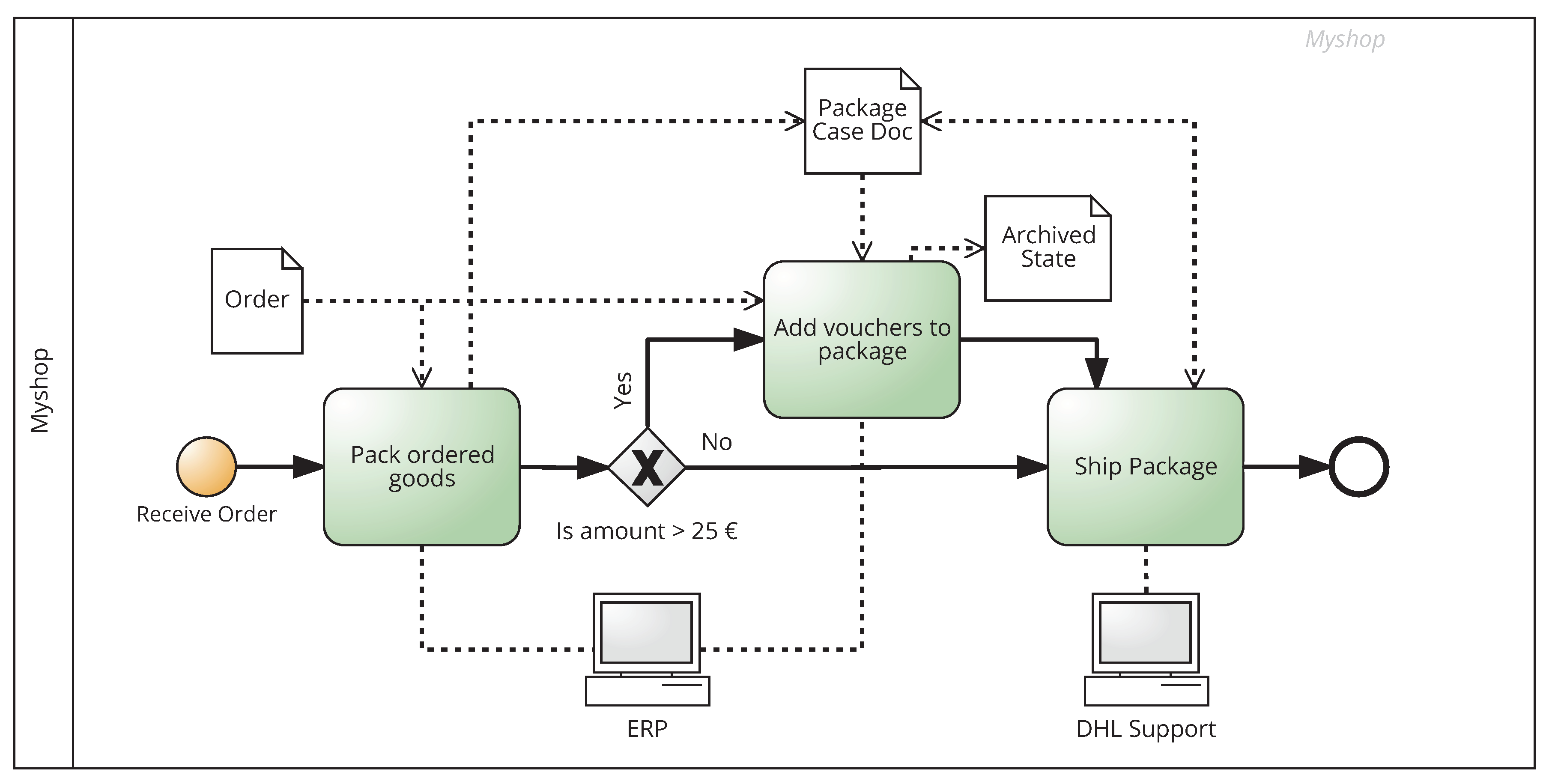
An example of transforming a spreadsheet to a process model according to the Branching approach from [26] is presented in Table 1 and the corresponding process model in Figure 1. Rows of the table represent model flow objects. Cells describe the properties of these objects (empty cell means that a particular property is not defined).
As it can be noticed, the second and third approaches require from the user some kind of familiarity with business process modeling notation. According to these approaches, the user has to specified such elements like gateways or successors. What is more, the More Properties approach is so complex that its efficiency gain is not worth the complexity that has to be taken into consideration when designing the spreadsheet. Thus, the second approach can be considered as most efficient and useful.
The main advantage of this approach is the clear overview of the represented workflow and as a consequence, facility to transform such a representation into a BPMN model. However, declaring flow objects or their relations explicitly, requires from the user a certain level of familiarity with business process modeling notations. In order to overcome this issue and make the spreadsheet representation more accessible for business users, we discussed the sketch of our approach in [13].
The detailed description of the approach is presented in the following section. Our approach solves the problem of familiarity with business process modeling notation. It consists in dividing the business process into phases and declaring branching flows implicitly, by indicating the appropriate phase number. A correct spreadsheet-based representation can be then used to generate a business process model.
3. Spreadsheet Representation of a Business Process
To clarify the understanding of what a business process is and how it can reflect the real-life workflows, Dumas et al. [28] identified common ingredients for business processes:
- activities—units of work performed manually or as an automated service, an atomic activity that cannot be divided is called a task,
- events—circumstances that happen without measurable duration,
- decision points—situation when a decision is made which affects the execution of the process,
- actors—process participants, seen as people, organization or software systems,
- physical objects—equipment, materials or documents,
- immaterial objects—electronic data, people’s knowledge,
- outcomes—final products or services, as well as negative outcomes e.g., refusals or error messages,
- customer—internal or external recipient of the outcome.
Table 2 describes how the different process ingredients are represented in the mentioned notations. The summary was based on [29,30,31]. The results of the comparative analysis show that, within the selected languages, only BPMN and UML Activity Diagrams can satisfy the requirement to represent all common process ingredients. However, according to the detailed comparison of UML and BPMN [32], BPMN process models can cover a larger number of business cases, including not only the process itself, but also specifications of the analyzed system in terms of its requirements and implementation.
Activities executed within a business process can be easily represented as an enumerated list in a tabular form. Such forms can be then saved as spreadsheet files. Taking into account the fact that spreadsheet editors are a popular means of storing and processing information in companies, they are also used for process modeling.
In the proposed solution, a business process is represented by a spreadsheet table, where rows correspond to tasks (or phases). Columns contain properties of the selected phase. Task and condition names should start with a capital letter, while all instructions are written in lowercase. Following column types are used:
- Order—the number of the corresponding phase (starting from one). If two or more tasks are performed in parallel or alternatively, we use letters to distinguish different branches, e.g., “2b”, “3a” etc. If a phase follows a logical gateway, its naming pattern is: where N is the natural number of the phase, x is a lowercase letter (a–z) representing the current branch and M is the natural number of the phase in this branch. If the branch contains only one activity, the letter M does not need to be included. In case when the process includes nested gateways, the names of its sub-phases are defined by extending the main phase number with the appropriate branch and sub-phase.
- Activity—name of the performed action or instruction. For example, if there is a need for a loop or skipping the phase, this field should be filled with a “goto” statement and number of the desired phase, e.g., “goto 7”.
- Condition—a condition needed to perform the selected action. If the task executes every time this field should be left empty. In order to implement a XOR-gateway this field should be filled with an appropriate condition and the word “else” for the other task performed in the same phase. In order to implement an OR-gateway the fields mentioned before should be filled with two separate conditions. This column is also used when events are triggered under certain conditions, e.g., after a determined amount of time.
- Who—a department or person that executes the task. This field corresponds to a swimlane.
- Input—data objects required by the corresponding activity as its input.
- Output—data objects generated by the corresponding activity as its output.
4. Approach Overview
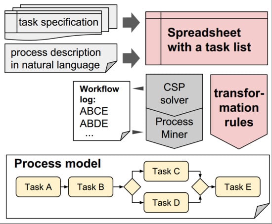
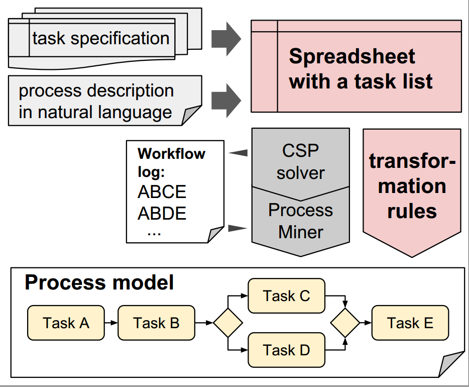
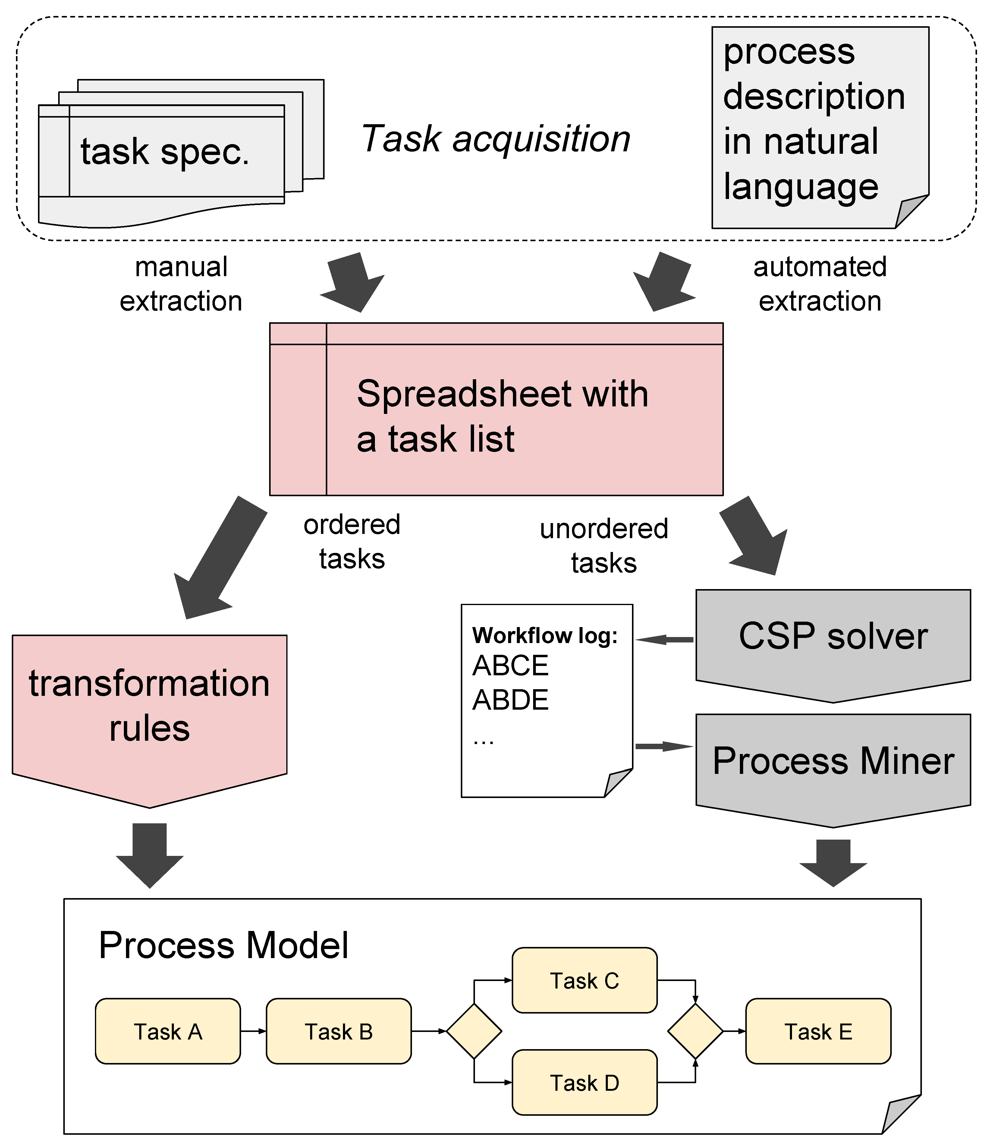
Our approach consists in generating business process models from spreadsheet-based representation. It is based on our preliminary workshop proposal presenting the method principles [13]. The context of the approach is presented in Figure 2. Our method consists of the following steps:
- Task acquisition—set of tasks can be represented in the form of a task list or acquired from the natural language description.
- Creating a spreadsheet with a task list—storing the tasks in the required spreadsheet-based representation:
- (a)
- manual spreadsheet extraction from structured task specification,
- (b)
- automated spreadsheet extraction from process description in natural language [14].
- Transformation into a BPMN process model:
- (a)
- for an ordered list of tasks—using rules for mapping spreadsheet representation into a process model,
- (b)
- for an unordered list of tasks—using model composition (e.g., using CSP solver and process mining methods [33]).
As a result, a process model is generated. The original contribution of this paper is the specification of creating the spreadsheet with ordered list and its transformation into a process model (i.e., steps 2 and 3a, highlighted in red in Figure 2).
In our solution, a business process can be described using one of the spreadsheet applications like MS Excel, Google Docs or OpenOffice Calc. Such a spreadsheet can be created either manually or merged from the task list specifications provided by users. It also can be generated from semi-formal or informal documents. Such solution was presented in [14], where this spreadsheet-based representation was used as an intermediate model when generating business process models.
Based on a CSV (Comma-Separated Values) file, which is a common representation of spreadsheet, of the model exported from the application, a graphical process model in BPMN can be generated according to the specified transformation rules. This requires an ordered list of tasks, which syntax is described in this paper. However, in the case of unordered list, it is also possible to solve the problem using constraint programming and some process construction or discovery methods [33,34]. Our spreadsheet-based process representation supports all basic BPMN elements. The subset of supported BPMN elements covers the most commonly used elements of BPMN diagram [15].
Although there are approaches providing the spreadsheet based representation for a process model [26,27], the method presented in this paper takes advantage of a nested list form and does not require explicit specification of gateways in the spreadsheet. Thus, a business user who defines tasks does not have to be skilled in process modeling in any business process notation.
5. Mapping a Spreadsheet with a BPMN Model
The translation method presented in this section transforms a spreadsheet-based representation into a BPMN 2.0 model. In the following subsections, we describe the requirements and assumptions that have been taken into account during method development. This includes the supported representation, as well as the detailed description of transformations to be performed.
5.1. Requirements
In order to make the solution widely applicable and simple to use, some assumptions were made. The following requirements need to be considered while providing a spreadsheet-based representation of a business process model:
- Users should be able to create a process model using one of the widely available spreadsheet applications (e.g., MS Excel, Google Docs, OpenOffice Calc).
- A graphical model should be created based on a CSV file (an exported spreadsheet).
- Only one pool is considered and the term "Who" is used instead of swimlane to distinguish different task performers.
- Logical gates are eliminated from the model. A process should be described as a set of phases. If two or more tasks are executed in the same phase, it means that they are parallel or connected by an alternative (OR/XOR). The relationship between tasks is determined by a condition stored in a separate column (no condition—AND, different conditions—OR, conditions and “else” statement—XOR). Table 3 shows how logical gates can be represented.
- Loops are represented by “goto” rows, which link one phase to another.
5.2. Supported Process Elements and Their Spreadsheet Model
The proposed approach supports the following process elements: start events, intermediate events, end events, tasks, logical gateways, swimlanes and data objects. These individual elements together with their spreadsheet model representation have been described in the subsections below and listed in Table 4.
5.2.1. Start Events
In the proposed model an assumption is made, that a business process starts in one specified moment, which is the so called “zero phase”. Table 5 presents examples of various start events. For different types of start events, the Activity field can denote the type while the Condition field describes the specific condition for the particular type of event.
In the case of general start event (without a specific type), the Activity field can be empty, and zero in the Order column denotes the starting point. In BPMN, this is represented by None Start Event. In other notations such a start event is represented just using an event at the beginning of the process. The overview of simple start and end events (without types of events) in various notations is presented in Figure 3.
5.2.2. Intermediate Events
In the case of intermediate events, the “Activity” field should contain the name of the appropriate event which starts with the lower case letter. Table 6 presents selected intermediate events and their spreadsheet representation. As the specific types of intermediate events are available only in BPMN and UML AD, we omit EPC, YAWL and Petri net representations. An intermediate event (without type) can be represented using an event in EPC or place in Petri net, which are represented in the same way as start or end events.
As boundary intermediate events exist only in the BPMN notation and are not the leading notation elements, we provide only a proposal of their spreadsheet representation. They can be represented simply just using the same number of process phase in the “Order” column, as presented in Table 7. As our goal is to provide a simple representation for process elements, which will be understandable for average business user, this is only a proposal not representing the full specification of the event (e.g., interrupting/non-interrupting issues).
5.2.3. End Events
For the end events the “Activity” field should contain the name of the appropriate end event. If this is just an end of the process without any particular type, it should be the last activity and can remain blank. Table 8 presents examples of various types of end events and their spreadsheet representation.
5.2.4. Tasks
The name of a task is stored in the “Activity” column and should start with a capital letter. To skip a phase or go back to a previous phase it is possible to use the “goto” statement in the activity field.
5.2.5. Parallel-, Exclusive- and Inclusive-Gateways
Gateways are represented by alternative branches in the sequence (phase) flow. A phase preceded by a logical gateway is named as follows: NxM, where N is the (natural) number of the phase in the main process branch, x is a letter (a–z) corresponding to the alternative branch and M is the number of the phase in the selected branch. If the branch contains only one task M can be omitted. We assume that the branching is always ended by the same type of gateway that started it. It may be perceived as a limitation, but in fact it prevents model inconsistency.
The representation of a simple AND-gateway was presented in Table 9.
In order to implement a XOR-gateway the field “Condition” should be filled with an appropriate condition and with the word “else” for the other task performed in the same phase, but in another branch. An example of a simple XOR-gateway was presented in Table 10.
In order to implement an OR-gateway the fields mentioned before should be filled with two separate conditions. An example of a simple OR-gateway was presented in Table 11.
A spreadsheet representation of multiple gateways was presented in Table 12.
5.2.6. Loops in the Process
Although a loop in a process model is not an element, but usually a structure of part of the process logic (In BPMN, a loop in a task or subprocess can be also represented using a loop marker. In such a case, it is not explicitly modeled using control flow.) we consider it similarly to gateway structures as one of the basic building block of a process model. Thus, in Table 13, we present a mapping between the loop structure representations.
5.2.7. Pools/Lanes
Different swimlanes present in a BPMN model are represented using fields in the column “Who” which contains the name of the appropriate department or the business entity that executes the corresponding tasks. An example of such model representation, which is the same in BPMN as in UML AD, is presented in Table 14.
5.2.8. Data Objects
There is possibility of representing data objects in process model in proposed approach. Table 15 presents the spreadsheet representation of input and output object.
5.3. Transformation Procedure
As it has been already mentioned before, the purpose of providing a spreadsheet-based representation of business processes is to facilitate process modeling for people who are unfamiliar with existing languages and notations. Therefore, an automated transformation of the exported spreadsheet into a BPMN diagram is a significant feature. The proposed algorithm uses a CSV file as input and generates a business process graph, which can be then mapped with a BPMN 2.0 XML file. The tabular representation of the business process is imported as an array of structures, where each row is a collection of elements which correspond to column names. An example transformation algorithm, which does not include model validation, is presented in Algorithm 1.
In order to simplify the structure of the represented algorithm (see Algorithm 1), several sub-procedures were used. Their meaning and usage is explained in the following points:
- —Retrieve the phase based on the current activity order without considering the current branch. The result of this function is a vector of natural numbers, the length of which corresponds to the branching depth. For example, in case of nested gateways as shown in Table 12, the phase vector for Task 1 will be equal to , while for Task 4 it will be .
- —Insert an isolated vertex into the process graph, identifiable by its alphanumeric Order.
- —Create a directed edge between and with weight vector .
- —Determine the precedence relation between two activities. This function returns a Boolean value which is true if the difference of the corresponding phase vectors is negative.
- —Select the set of edges with the lowest non-zero weight vectors and keep them in the graph. Remove from all the remaining edges, unless the removal isolates one of the graph vertices.
- —Identify parallel relations by grouping neighbour vertices in the same phase. If activities in a group have no or the same conditions, then connect them with a parallel gateway. If among the conditions there is a keyword “else” then use an exclusive gateway. Otherwise connect the group of vertices with an inclusive (OR) gateway.
| Algorithm 1: Generating a business process graph based on a spreadsheet description. |
 |
6. Evaluation
For evaluation of our solution, we compared it to the current interchange standards for business process representation (Section 6.1). Moreover, we provided case study examples depicting how to use the proposed approach (Section 6.2).
6.1. Interchange Solution
Currently, there are several interchange formats between different Business Process Modelling (BPM) techniques. Most are based on XML and have different properties [35]. The below summary presents an overview of the commonly used formats:
- BPEL4WS (Business Process Execution Language) also known as BPEL (Business Process Execution Language) is an OASIS standard executable language using web services for specifying actions within business processes. It is referred to as an interchange format only via an XML Schema [36].
- BPML (Business Process Modeling Language is an language for business process modeling based on XML [37].
- BPMN (Business Process Model and Notation) offers two XML formats for storing BPMN processes: a format defined using XML Schema Definition (XSD) and a format defined using XML Metadata Interchange (XMI) [38].
- BPSS (Business Process Specification Schema) includes a metamodel and XML Schema for Web Service choreography. It works on ebXML (Electronic Business using eXtensible Markup Language) [39].
- EPML (Event-Driven Process Chain Markup Language) is XML-based interchange format for event-driven process chains [40]. OWL-S (OWL-Services) is an ontology of services represented in OWL (Ontology Web Language) and builds on an (input-output-preconditions-effects) quadruple to describe services [41].
- PNML (Petri Net Markup Language) is an XML interchange format for Petri net models and for High-level Petri nets in particular. The PNML is currently under the final ballot as ISO/IEC Standard 15909-2 [42,43]. UML 2 Activity Diagram (Activity Diagrams of Unified Modeling Language can be exchanged using XMI [44].
- WSCDL (W3C’s Web Service Choreography Description Language) is a choreography language that describes peer-to-peer collaborations of participants by defining their common and complementary observable behaviors from a global viewpoint [45].
- WSCI (W3C’s Web Service Choreography Interface) is focused on the choreography of Web services and provides a set of extensions to WSDL in order to describe process behavior of message exchanges [46].
- WSCL (Web Service Conversation Language) allows defining the abstract interfaces of web services, i.e., the business level conversations or public processes supported by a web service and specifies the XML documents being exchanged [47].
- WSFL (Web Services Flow Language) is an XML language, provided by IMB, for the description of Web Services compositions where control flow is modelled via directed Graphs [48].
- XPDL (XML Process Definition Language is a format standardized by the Workflow Management Coalition to interchange business process definitions between different modeling tools, BPM suites, workflow engines and other software applications [51].
The spreadsheet is compared with other BPM interchange formats in Table 16. Our goal in this comparison is to show the place of spreadsheet-based representation in supporting common process elements. Plus and minus signs denote if a particular structure or element is supported (or not) by the interchange formats mentioned above. As one can observe, some interchange formats support more elements, constructs or objects. However, these representation often require from user much knowledge about the process modeling and the particular notation. Moreover, each of these solutions has some limitations, e.g., BPEL4WS supports block-structured constructs, so the translation of unstructured acyclic fragments of process models to BPEL4WS is a very complex task and such a model can be illegible.
6.2. Case Studies
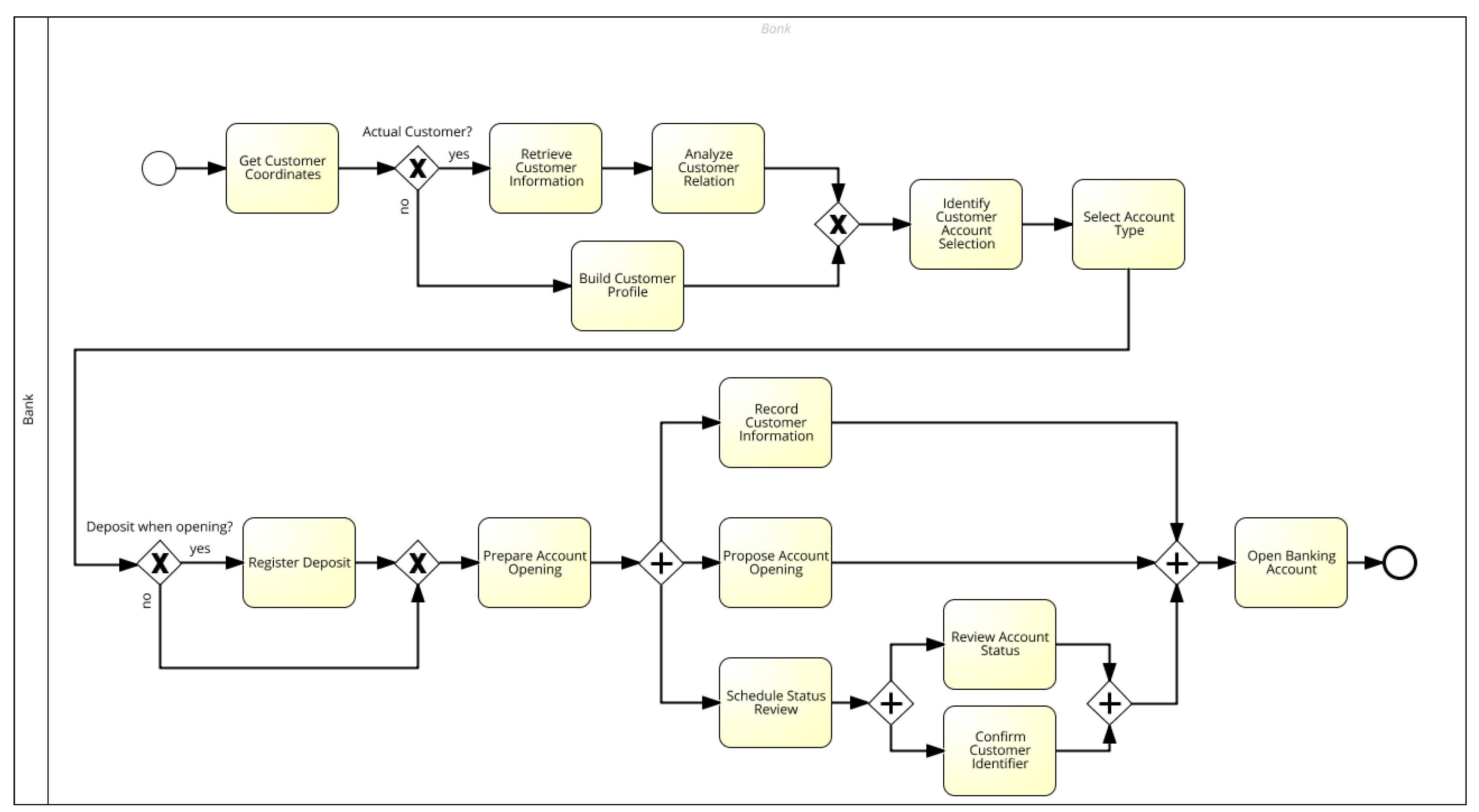
For the evaluation of our method, we present an example of the “Bank account opening” business process. Table 17 shows the spreadsheet describing the process. The corresponding diagram is presented in Figure 4.
One can noticed that our approach supports fewer elements than such complex approaches as Branching or More Properties approaches. However, the other approaches support the elements in a straightforward way, requiring the deeper knowledge of business process elements, even in the case of such simple structures like gateways.
Moreover, there are several points, in which our approach has the advantage over the existing approaches:
- We do not use explicit notion of XOR/OR/AND gateways, thus the user does not have to think about the kind of flow branching. Instead, in our model it is modeled in the implicit way.
- For describing the condition, we use the “condition” column, what is more clear than using the “description” field.
- We do not use the notion of “Successor” as it does not always show clearly the flow in the spreadsheet representation. Thus, in our opinion, a well-known jump statement “goto” (one-way control flow transfer), existing in many computer programming languages, in this particular usage performs better, as it is clearly visible in the Activity field.
Although we do not consider data flow in our model, it is possible to add this kind of perspective in the exactly the same way, as it was proposed in [26]—by adding two new columns: Input and Output column (as presented in Table 1).
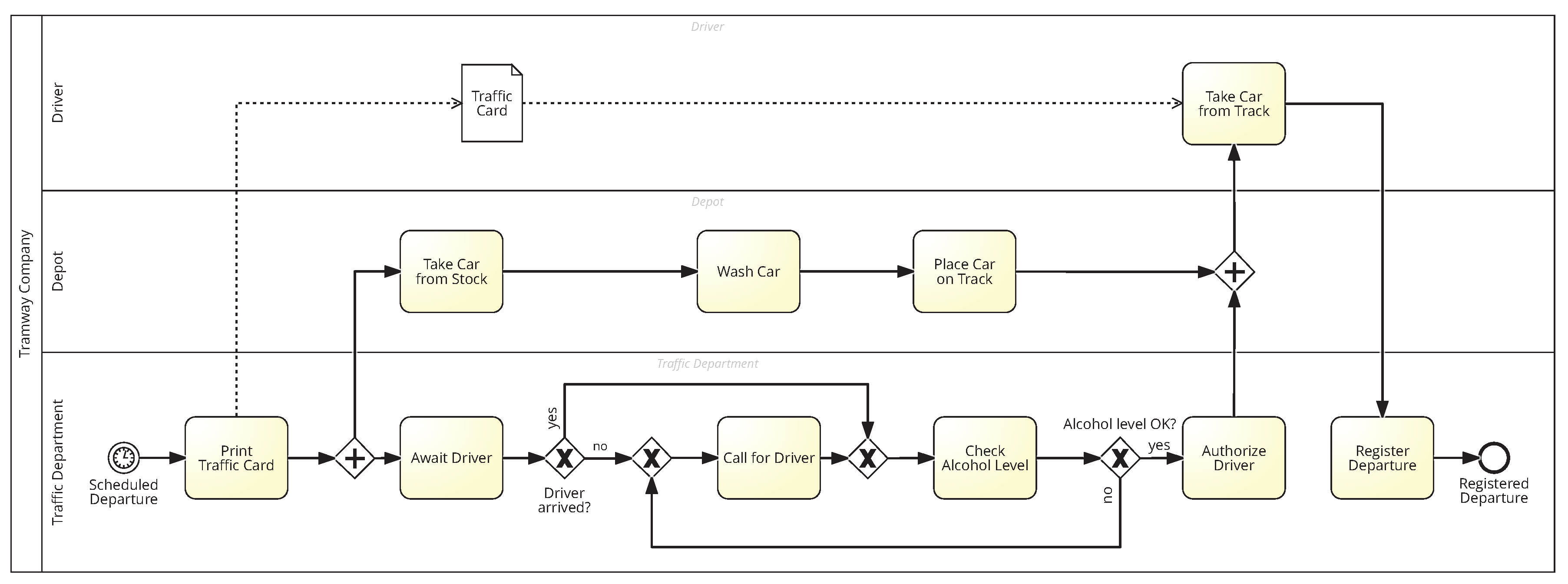
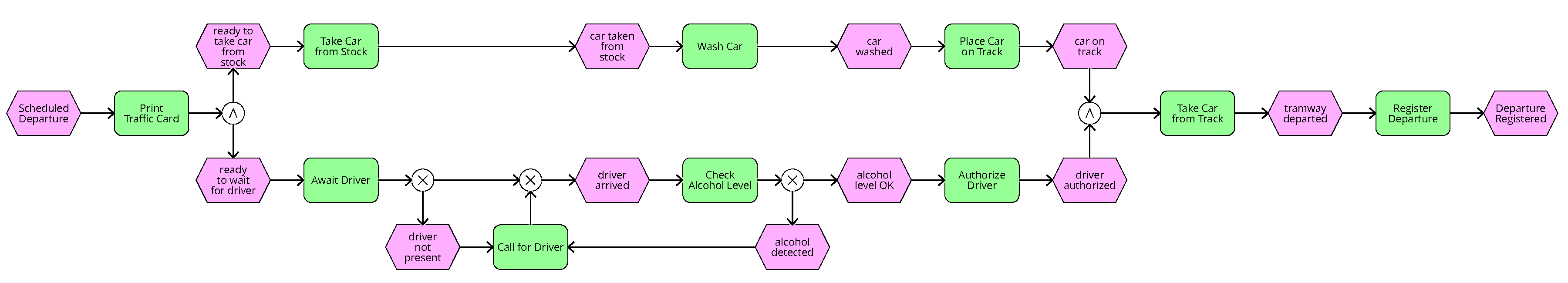
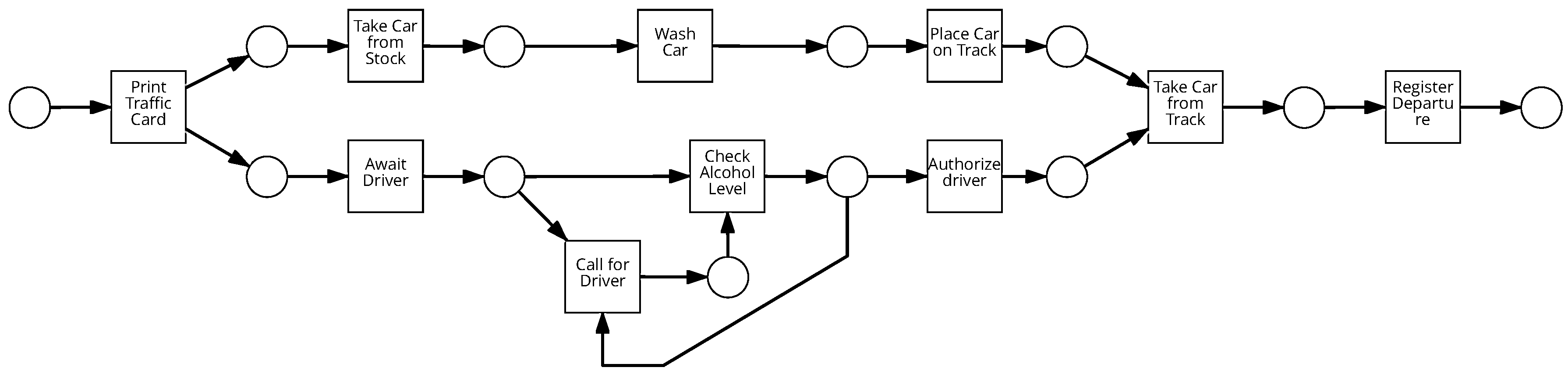
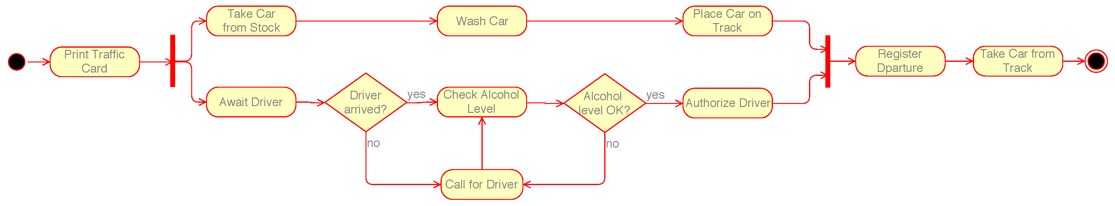
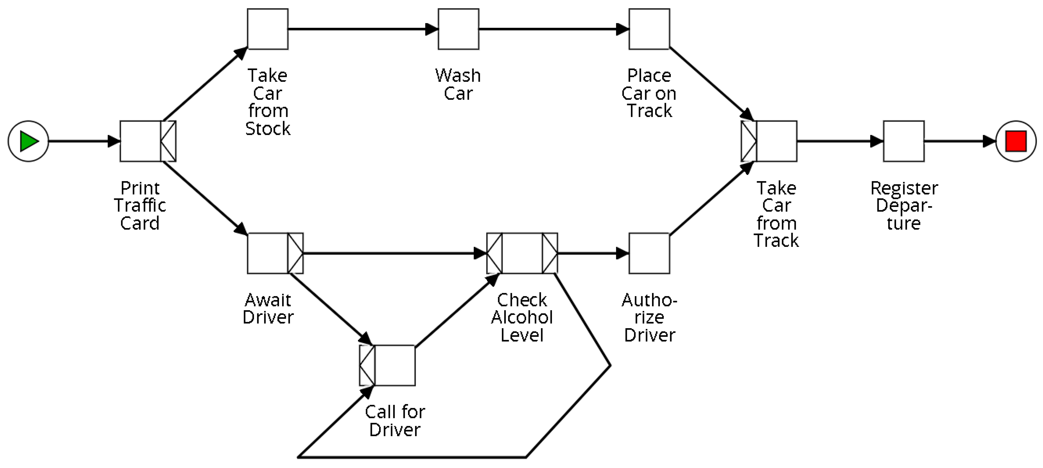
To illustrate the idea of spreadsheet representation and its interoperability, a sample model of tramway departure process was selected. The BPMN model of this process is shown in Figure 5, while Figure 6, Figure 7, Figure 8 and Figure 9 illustrate this process in different modeling notations, namely: EPC, Petri net, UML AD and YAWL. The goal of this process is the preparation of a tramway car to leave the storage yard in the morning. In the workflow, there are two organizational participants: the Depot which is responsible for storing and servicing the rolling stock and the Traffic Department which controls and manages the daily operations, as well as the human actor, represented by the driver. The desired outcome of the process is the successful departure of the car from the depot which results in starting regular service with passengers. Based on the departure time taken from the schedule, the Traffic Department prepares and prints the Traffic Card which serves as the main document for the driver. In the next step, two parallel chains of activities are executed. The Depot prepares the car for the daily service while the Traffic Department awaits the driver. If the driver does not arrive, a next employee is called to come. Then, the driver is tested fot alcohol level in the exhaled air. If alcohol is detected, a new driver is called and the testing procedure is repeated. Finally, when the tramway car is ready for departure and the driver is authorized to work, the car can be taken by the driver from the outbound track. The process ends when the Traffic Department registers the departure in their systems.
Table 19 presents the overall comparison of our approach to the existing approaches in in terms of supported elements by these solutions.
6.3. Additional Remarks
For correct interpretation, our spreadsheet-based representation requires at least two columns: “Order” and “Activity”. Such a model will represent a simple workflow without swimlanes or gateways. Other columns (“Condition”, “Who”, “Input”, “Output”) are optional. It is also possible to extend the representation with custom columns, e.g., “Description” or “Comments”, which will be ignored, unless additionally implemented.
If the process description is shorter then the complete process, it can be parsed normally. However, it will lack of the end event (unless there is an end event row). The order numbers do not have to be complete. However, in the case of the gateway representation, it requires consecutive letters in the “Order” column.
In our approach we use the “goto” statement, although in software developer environment, the “goto” statement is considered as outdated or deprecated. However, recent studies [52] show that even today in programming languages, “goto” is used in projects. But it is mostly limited to the cases where it actually offers an improvement over the alternatives. The jump instruction such as “goto” is a popular way of dealing with loops or skipping some steps in algorithms. Thus, it is used in instructions or manuals [53]. It can take various forms, such as: go back to the step A, see the point B, check page C, contact D. Moreover, models are not always designed in a proper (elegant) way, and “goto” can handle such situations. In our case, the “goto” statement makes the process spreadsheet more readable and easier to follow. Such representation is also smaller because it gets rid of steps duplication. The possibility of extending the representation with other structures replacing the “goto” statement should be a part of the future extensive evaluation on users.
7. Conclusions
We presented a concept of mapping process model elements in various notations into a spreadsheet representation. In our solution, we proposed a convenient knowledge representation which can serve as an interchange format for different modeling languages. The idea is supported by the method to automate the generation of BPMN models based on a provided spreadsheet-based representation. A significant advantage of our approach is the possibility to design process models using a variety of spreadsheet editors. Since a process modeler does not need to explicitly declare flow objects such as gateways, this approach does not require a high level of familiarity with any of the existing process notation.
As future works, we plan to extend the method in terms of the support of advanced business process diagrams and their elements. At the first stage, we would like to represent collaboration between multiple pools, including message flows. In the next steps, we are planning to develop a software tool to enable transformation of different process models into a spreadsheet which can serve as an interchange format as well as be a base for process comparison [54] or validation [55].
In parallel to the extension of the technical capabilities, we plan to verify the applicability of our approach on a group of users from different companies within the Small and Medium-sized Enterprises (SME) sector. The results of such an analysis will show us the suitability of the method for modeling different kinds of business processes and the efficiency of using spreadsheet editors as modeling tools.
Author Contributions
Conceptualization, P.W. and K.K.; Formal analysis, E.K. and A.L.; Funding acquisition, E.K. and A.L.; Methodology, P.W. and K.K.; Project administration, E.K.; Resources, A.L.; Software, P.W.; Supervision, A.L.; Validation, K.K. and A.L.; Visualization, P.W. and K.K.; Writing – original draft, P.W. and K.K.; Writing—review & editing, E.K. and A.L.
Funding
The research reported in this paper as well as the open access charge were financed by the AGH UST grant.
Conflicts of Interest
The authors declare no conflict of interest.
References
- Mercier-Laurent, E. Knowledge management &risk management. In Proceedings of the IEEE 2016 Federated Conference on Computer Science and Information Systems (FedCSIS), Gdańsk, Poland, 11–14 September 2016; pp. 1369–1373. [Google Scholar]
- Friedrich, F.; Mendling, J.; Puhlmann, F. Process Model Generation from Natural Language Text. In Proceedings of the 23rd International Conference on Advanced Information Systems Engineering, London, UK, 20–24 June 2011; Springer: Berlin/Heidelberg, Germany, 2011; pp. 482–496. [Google Scholar]
- Ghose, A.; Koliadis, G.; Chueng, A. Process Discovery from Model and Text Artefacts. In Proceedings of the 2007 IEEE Congress on Services, Salt Lake City, UT, USA, 9–13 July 2007; pp. 167–174. [Google Scholar]
- De AR Goncalves, J.C.; Santoro, F.M.; Baiao, F.A. Business process mining from group stories. In Proceedings of the IEEE 2009 13th International Conference on Computer Supported Cooperative Work in Design (CSCWD 2009), Santiago, Chile, 22–24 April 2009; pp. 161–166. [Google Scholar]
- Yue, T.; Briand, L.C.; Labiche, Y. An Automated Approach to Transform Use Cases into Activity Diagrams. In Proceedings of the 6th European Conference on Modelling Foundations and Applications, Paris, France, 15–18 June 2010; Springer: Berlin/Heidelberg, Germany, 2010; pp. 337–353. [Google Scholar]
- Ferreira, R.C.B.; Thom, L.H.; Fantinato, M. A semi-automatic approach to identify business process elements in natural language texts. In Proceedings of the 19th International Conference on Enterprise Information Systems, Porto, Portugal, 26–29 April 2017. [Google Scholar]
- Riefer, M.; Ternis, S.F.; Thaler, T. Mining process models from natural language text: A state-of-the-art analysis. In Proceedings of the Multikonferenz Wirtschaftsinformatik (MKWI-16), Illmenau, Germany, 9–11 March 2016. [Google Scholar]
- Njonko, P.B.F.; El Abed, W. From natural language business requirements to executable models via SBVR. In Proceedings of the 2012 International Conference on Systems and Informatics (ICSAI), Yantai, China, 19–20 May 2012; pp. 2453–2457. [Google Scholar]
- Kluza, K.; Honkisz, K. From SBVR to BPMN and DMN Models. Proposal of Translation from Rules to Process and Decision Models. In Artificial Intelligence and Soft Computing; Lecture Notes in Computer Science; Rutkowski, L., Korytkowski, M., Scherer, R., Tadeusiewicz, R., Zadeh, L.A., Zurada, J.M., Eds.; Springer: Berlin/Heidelberg, Germany, 2016; Volume 9693, pp. 453–462. [Google Scholar]
- De Oliveira, J.P.M.; Avila, D.T.; dos Santos, R.I.; Fantinato, M. Assisting Process Modeling by Identifying Business Process Elements in Natural Language Texts. In Advances in Conceptual Modeling: ER 2017 Workshops AHA, MoBiD, MREBA, OntoCom, and QMMQ, Valencia, Spain, 6–9 November 2017; Springer: Cham, Switzerland, 2017; Volume 10651, p. 154. [Google Scholar]
- Kluza, K.; Nalepa, G.J.; Ślażyński, M.; Kutt, K.; Kucharska, E.; Kaczor, K.; Łuszpaj, A. Overview of selected business process semantization techniques. In Advances in Business ICT: New Ideas from Ongoing Research; Springer: Cham, Switzerland, 2017; pp. 45–64. [Google Scholar]
- Sokolov, K.; Timofeev, D.; Samochadin, A. Process Extraction from Texts using Semantic Unification. In Proceedings of the 7th International Conference on Knowledge Management and Information Sharing (KMIS 2015), Lisbon, Portugal, 12–14 November 2015; pp. 254–259. [Google Scholar]
- Kluza, K.; Wiśniewski, P. Spreadsheet-based Business Process modeling. In Proceedings of the 2016 Federated Conference on Computer Science and Information Systems (FedCSIS), Gdańsk, Poland, 11–14 September 2016; pp. 1355–1358. [Google Scholar]
- Honkisz, K.; Kluza, K.; Wiśniewski, P. A Concept for Generating Business Process Models from Natural Language Description. In Proceedings of the International Conference on Knowledge Science, Engineering and Management, Changchun, China, 17–19 August 2018; Springer: Berlin/Heidelberg, Germany, 2018; pp. 91–103. [Google Scholar]
- Zur Muehlen, M.; Recker, J. How much language is enough? Theoretical and practical use of the business process modeling notation. In Proceedings of the International Conference on Advanced Information Systems Engineering, Montpellier, France, 16–20 June 2008; Springer: Berlin/Heidelberg, Germany, 2008; pp. 465–479. [Google Scholar]
- Levy, F.; Nazarenko, A. Formalization of Natural Language Regulations through SBVR Structured English. In Theory, Practice, and Applications of Rules on the Web; Lecture Notes in Computer Science; Morgenstern, L., Stefaneas, P., Levy, F., Wyner, A., Paschke, A., Eds.; Springer: Berlin/Heidelberg, Germany, 2013; Volume 8035, pp. 19–33. [Google Scholar] [CrossRef]
- Raj, A.; Prabhakar, T.V.; Hendryx, S. Transformation of SBVR Business Design to UML Models. In Proceedings of the 1st India Software Engineering Conference (ISEC’08), Hyderabad, India, 19–22 February 2008; ACM: New York, NY, USA, 2008; pp. 29–38. [Google Scholar]
- Tantan, O.C.; Akoka, J. Automated transformation of Business Rules into Business Processes. In Proceedings of the Twenty-Sixth International Conference on Software Engineering and Knowledge Engineering, Vancouver, BC, Canada, 1–3 July 2014; pp. 684–687. [Google Scholar]
- Raj, A.; Agrawal, A.; Prabhakar, T.V. Transformation of Business Processes into UML Models: An SBVR Approach. Int. J. Sci. Eng. Res. 2013, 4, 647–661. [Google Scholar]
- Steen, B.; Pires, L.; Iacob, M.E. Automatic Generation of Optimal Business Processes from Business Rules. In Proceedings of the 2010 14th IEEE International Enterprise Distributed Object Computing Conference Workshops (EDOCW), Vitoria, Brazil, 25–29 October 2010; pp. 117–126. [Google Scholar] [CrossRef]
- Nawrocki, J.R.; Nedza, T.; Ochodek, M.; Olek, L. Describing Business Processes with Use Cases. In Proceedings of the 9th International Conference on Business Information Systems (BIS 2006), Klagenfurt, Austria, 31 May–2 June 2006; pp. 13–27. [Google Scholar]
- Lubke, D.; Schneider, K.; Weidlich, M. Visualizing Use Case Sets as BPMN Processes. In Proceedings of the Requirements Engineering Visualization, 2008 (REV ‘08), Barcelona, Spain, 8 September 2008; pp. 21–25. [Google Scholar]
- Klimek, R.; Faber, L.; Kisiel-Dorohinicki, M. Verifying data integration agents with deduction-based models. In Proceedings of the 2013 Federated Conference on Computer Science and Information Systems (FedCSIS), Kraków, Poland, 8–11 September 2013; pp. 1029–1035. [Google Scholar]
- Van der Aalst, W.M.P. Process Mining: Discovery, Conformance and Enhancement of Business Processes, 1st ed.; Springer: Berlin/Heidelberg, Germany, 2011. [Google Scholar]
- Kalenkova, A.A.; de Leoni, M.; van der Aalst, W.M. Discovering, Analyzing and Enhancing BPMN Models Using ProM? In Proceedings of the Business Process Management-12th International Conference (BPM), Eindhoven, The Netherlands, 20 September 2014; pp. 7–11. [Google Scholar]
- Krumnow, S.; Decker, G. A Concept for Spreadsheet-Based Process Modeling. In Business Process Modeling Notation: Second International Workshop, BPMN 2010, Potsdam, Germany, October 13–14, 2010; Springer: Berlin/Heidelberg, Germany, 2010; pp. 63–77. [Google Scholar]
- Krumnow, S. Spreadsheet-based process modeling. In Business Processes in the Real World; Springer: Berlin/Heidelberg, Germany, 2010; pp. 55–70. [Google Scholar]
- Dumas, M.; La Rosa, M.; Mendling, J.; Reijers, H.A. Fundamentals of Business Process Management; Springer: Berlin/Heidelberg, Germany, 2013; Volume 1. [Google Scholar]
- Kluza, K.; Jobczyk, K.; Wiśniewski, P.; Ligęza, A. Overview of Time Issues with Temporal Logics for Business Process Models. In Proceedings of the 2016 Federated Conference on Computer Science and Information Systems, Gdansk, Poland, 11–14 September 2016; pp. 1115–1123. [Google Scholar] [CrossRef]
- List, B.; Korherr, B. An evaluation of conceptual business process modelling languages. In Proceedings of the 2006 ACM Symposium on Applied Computing, Dijon, Frankreich, 23–27 April 2006; pp. 1532–1539. [Google Scholar]
- Weske, M. Business Process Management: Concepts, Languages, Architectures, 2nd ed.; Springer: Berlin/Heidelberg, Germany, 2012. [Google Scholar]
- Kluza, K.; Wiśniewski, P.; Jobczyk, K.; Ligęza, A.; Suchenia (Mroczek), A. Comparison of selected modeling notations for process, decision and system modeling. In Proceedings of the 2017 Federated Conference on Computer Science and Information Systems (FedCSIS), Prague, Czech Republic, 3–6 September 2017; pp. 1095–1098. [Google Scholar]
- Wiśniewski, P.; Kluza, K.; Ligęza, A. An Approach to Participatory Business Process Modeling: BPMN Model Generation Using Constraint Programming and Graph Composition. Appl. Sci. 2018, 8, 1428. [Google Scholar] [CrossRef]
- Parody, L.; Gómez-López, M.; Varela-Vaca, A.; Gasca, R. Business Process Configuration according to Data Dependency Specification. Appl. Sci. 2018, 8, 2008. [Google Scholar] [CrossRef]
- Mendling, J.; Neumann, G.; Nüttgens, M. A Comparison of XML Interchange Formats for Business Process Modelling. EMISA 2004, 56, 129–140. [Google Scholar]
- Andrews, T.; Curbera, F.; Dholakia, H.; Goland, Y.; Klein, J.; Leymann, F.; Liu, K.; Roller, D.; Smith, D.; Thatte, S.; et al. Business Process Execution Language for Web Services. Technical Report. Microsoft, IBM, Siebel Systems, BEA, and SAP. 2003. Available online: http://xml.coverpages.org/BPELv11-20030505-20030331-Diffs.pdf (accessed on 20 January 2019).
- Mili, H.; Tremblay, G.; Jaoude, G.B.; Lefebvre, É.; Elabed, L.; Boussaidi, G.E. Business process modeling languages: Sorting through the alphabet soup. ACM Comput. Surv. (CSUR) 2010, 43, 4. [Google Scholar] [CrossRef]
- Kurz, M. BPMN model interchange: The quest for interoperability. In Proceedings of the 8th International Conference on Subject-oriented Business Process Management, Erlangen, Germany, 7–8 April 2016; p. 6. [Google Scholar]
- Clark, J.; Casanave, C.; Kanaskie, K.; Harvey, B.; Smith, N.; Yunker, J.; Riemer, K. ebXML Business Process Specification Schema Version 1.01. Technical Report. UN/CEFACT and OASIS. 2001. Available online: http://www.ebxml.org/specs/ebBPSS.pdf (accessed on 20 January 2019).
- Mendling, J.; Nüttgens, M. EPC markup language (EPML): An XML-based interchange format for event-driven process chains (EPC). Inf. Syst. e-Bus. Manag. 2006, 4, 245–263. [Google Scholar] [CrossRef]
- Martin, D.; Burstein, M.; Hobbs, J.; Lassila, O.; McDermott, D.; McIlraith, S.; Narayanan, S.; Paolucci, M.; Parsia, B.; Payne, T.; et al. OWL-S: Semantic Markup for Web Services. W3C Member Submission. Available online: https://www.w3.org/Submission/OWL-S/ (accessed on 20 January 2019).
- Hillah, L.M.; Kordon, F.; Petrucci, L.; Treves, N. PNML Framework: An extendable reference implementation of the Petri Net Markup Language. In Proceedings of the International Conference on Applications and Theory of Petri Nets, Braga, Portugal, 21–25 June 2010; Springer: Berlin/Heidelberg, Germany, 2010; pp. 318–327. [Google Scholar]
- Kindler, E. The ePNK: An extensible Petri net tool for PNML. In Proceedings of the International Conference on Application and Theory of Petri Nets and Concurrency, Newcastle, UK, 20–24 June 2011; Springer: Berlin/Heidelberg, Germany, 2011; pp. 318–327. [Google Scholar]
- Unified Modeling Language; Object Management Group: Needham, MA, USA, 2001; Available online: https://www.omg.org/spec/UML/1.4 (accessed on 20 January 2019).
- Tasharofi, S.; Sirjani, M. Formal modeling and conformance validation for WS-CDL using Reo and CASM. Electron. Notes Theor. Comput. Sci. 2009, 229, 155–174. [Google Scholar] [CrossRef]
- Sheng, Q.Z.; Qiao, X.; Vasilakos, A.V.; Szabo, C.; Bourne, S.; Xu, X. Web services composition: A decade’s overview. Inf. Sci. 2014, 280, 218–238. [Google Scholar] [CrossRef]
- Chopella, V.; Govindarajan, K.; Karp, A.; Kuno, H.; Lemon, M.; Pogossiants, G.; Sharma, S.; Williams, S. Web Services Conversation Language (WSCL) 1.0. Technical Report. W3C, 2002. Available online: https://www.w3.org/TR/wscl10/ (accessed on 20 January 2019).
- Frank, L. Web Services Flow Language (WSFL 1.0). Technical Report. IBM Software Group, 2001. Available online: https://d3s.mff.cuni.cz/research/seminar/download/2002-04-24-Gergic-wsfl.pdf (accessed on 20 January 2019).
- Thatte, S. XLANG: Web Services for Business Process Design. Microsoft Corporation. 2001, Volume 2001. Available online: http://xml.coverpages.org/XLANG-C-200106.html (accessed on 20 January 2019).
- Weske, M. Business process management architectures. In Business Process Management; Springer: Berlin, Germany, 2012; pp. 333–371. [Google Scholar]
- Palmer, N. XML Process Definition Language. In Encyclopedia of Database Systems; Springer-Verlag: Boston, MA, USA, 2016; p. 1. [Google Scholar]
- Nagappan, M.; Robbes, R.; Kamei, Y.; Tanter, É.; McIntosh, S.; Mockus, A.; Hassan, A.E. An empirical study of goto in C code from GitHub repositories. In Proceedings of the 2015 10th Joint Meeting on Foundations of Software Engineering, Bergamo, Italy, 30 August–4 September 2015; pp. 404–414. [Google Scholar]
- Berry, E. How to get users to follow procedures. IEEE Trans. Prof. Commun. 1982, PC-25/1, 22–25. [Google Scholar] [CrossRef]
- Armas-Cervantes, A.; Dumas, M.; García-Bañuelos, L.; Polyvyanyy, A. On the suitability of generalized behavioral profiles for process model comparison. In Web Services, Formal Methods, and Behavioral Types; Springer: Cham, Switzerland, 2014; pp. 13–28. [Google Scholar]
- Mach, M.A.; Owoc, M.L. Validation as the integral part of a knowledge management process. In Proceedings of the Informing Science Conference, Krakow, Poland, 19–22 June 2001. [Google Scholar]
Figure 1.
An example of an equivalent model to the spreadsheet-based process description presented in Table 1 (based on [26]).

Figure 2.
Overview of the spreadsheet-based approach and its place in the context of process modeling.
Figure 2.
Overview of the spreadsheet-based approach and its place in the context of process modeling.

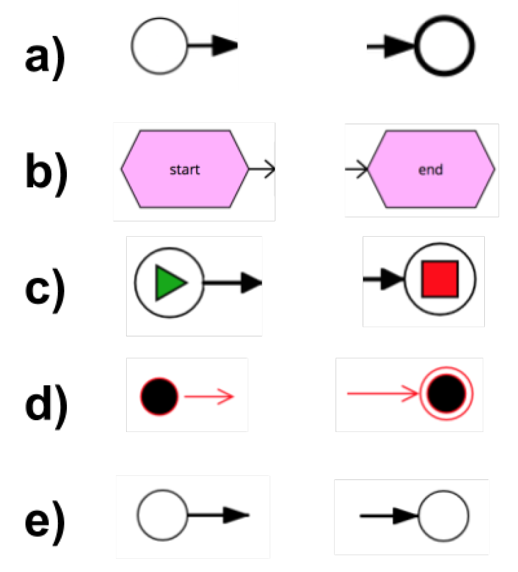
Figure 3.
Start and end events (without a specific type) in various process representations: (a) BPMN, (b) EPC, (c) YAWL, (d) UML AD, (e) Petri Nets.
Figure 3.
Start and end events (without a specific type) in various process representations: (a) BPMN, (b) EPC, (c) YAWL, (d) UML AD, (e) Petri Nets.

Figure 4.
An example of an equivalent model to the spreadsheet-based process description presented in Table 17.
Figure 4.
An example of an equivalent model to the spreadsheet-based process description presented in Table 17.

Figure 5.
An example of an equivalent model to the spreadsheet-based process description presented in Table 18.
Figure 5.
An example of an equivalent model to the spreadsheet-based process description presented in Table 18.

Figure 6.
An example of an equivalent model to the spreadsheet-based process description presented in Table 18.
Figure 6.
An example of an equivalent model to the spreadsheet-based process description presented in Table 18.

Figure 7.
An example of an equivalent model to the spreadsheet-based process description presented in Table 18.
Figure 7.
An example of an equivalent model to the spreadsheet-based process description presented in Table 18.

Figure 8.
An example of an equivalent model to the spreadsheet-based process description presented in Table 18.
Figure 8.
An example of an equivalent model to the spreadsheet-based process description presented in Table 18.

Figure 9.
An example of an equivalent model to the spreadsheet-based process description presented in Table 18.
Figure 9.
An example of an equivalent model to the spreadsheet-based process description presented in Table 18.


Table 1.
An example of a spreadsheet-based process model from [26].
Table 1.
An example of a spreadsheet-based process model from [26].
| 1. | Name | Description | Input | Output | Assignee | Firm | IT System | Successor | (..) |
|---|---|---|---|---|---|---|---|---|---|
| 2. | Receive Order | ||||||||
| 3. | Pack ordered goods | Order | Package Case Doc | Storage D | Myshop | ERP | |||
| 4. | XOR | Is amount > 25 | 5, 6 | ||||||
| 5. | Add vouchers to package | Order, Package Case Doc | Archived State | Shipment D | Myshop | ERP | 6 | ||
| 6. | Ship Package | Package Case Doc | Package Case Doc | Shipment D | Myshop | DHL Support |
Table 2.
Business process ingredients represented by different modeling notations.
| Ingredient | BPMN | Petri Nets | EPC | UML AD | YAWL | Spreadsheet |
|---|---|---|---|---|---|---|
| Activities | Activities | Transitions | Functions | Activities | Tasks | Activity |
| Events | Events | N/A | Events | Send/Receive | N/A | Activity |
| Signals | ||||||
| Decision | OR/XOR | Alternative | Connectors | Decision | OR/XOR | Condition |
| Points | Gateways | Paths | Nodes | Tasks | ||
| Actors | Swimlanes | N/A | Organization | Partitions | N/A | Who |
| N/A | Units | |||||
| Objects | Artifacts | N/A | Information | Object | N/A | Input/Output |
| Resources | Nodes | |||||
| Outcomes | End Events | Final Marking | Final Events | End Nodes | Output | Activity |
| Condition | ||||||
| Customer | Pool | N/A | N/A | Partitions | N/A | N/A |
Table 3.
Simple example of a XOR-gateway implementation.
| Order | Activity | Condition | (..) |
|---|---|---|---|
| 4a | Send Ticket | Payment registered | |
| 4b | goto 6 | else | |
| 5 | ... | ... | |
| 6 | ... | ... |
Table 4.
A concise overview of elements that can be modeled within the proposed solution.
| Element Type | Our Approach | Additional Comment |
|---|---|---|
| Task | yes | no task types |
| Events | yes | |
| AND, OR and XOR Gateway | yes | |
| Pool, Lane | partially | only one pool considered |
| Data Object | yes | |
| Sequence Flow | yes | |
| Message Flow | no |
Table 5.
Start event examples.

Table 6.
Intermediate event examples.

Table 7.
Boundary intermediate event.

Table 8.
End event examples.

Table 9.
AND-gateway example.

Table 10.
XOR-gateway example.

Table 11.
OR-gateway example.

Table 12.
Multiple (nested) gateways example.

Table 13.
Loop structure example.

Table 14.
Swimlanes example.

Table 15.
Data object example.

Table 16.
A comparison of spreadsheet with BPM Interchange Formats (based on [35]).
Table 16.
A comparison of spreadsheet with BPM Interchange Formats (based on [35]).
| BPEL4WS | BPML | BPMN | BPSS | EPML | OWL-S | PNML | UML Act.D. | WS-CDL | WSCI | WSCL | WSFL | XLANG | XPDL | Spreadsheet | |
|---|---|---|---|---|---|---|---|---|---|---|---|---|---|---|---|
| Task | + | + | + | + | - | + | - | + | + | + | + | + | + | + | + |
| Task Input/Output | + | + | + | + | - | + | - | + | + | + | + | + | + | + | + |
| Task Address | + | + | + | - | - | + | - | - | + | + | + | + | + | + | - |
| Quality Attributes | - | - | - | + | - | + | - | - | - | - | - | + | - | - | - |
| Protocol | + | - | + | - | - | + | - | - | + | + | + | + | + | - | - |
| Control Flow | + | + | + | + | + | + | + | + | + | + | + | + | + | + | + |
| Data Handling | + | + | + | - | - | - | - | + | + | - | - | + | - | + | + |
| Instance Identity | + | + | - | - | - | - | - | - | - | + | - | + | + | - | - |
| Roles | + | + | + | + | - | + | - | + | + | + | - | + | + | + | + |
| Events | + | + | + | - | + | - | - | - | - | - | - | + | + | + | + |
| Exceptions | + | + | + | + | - | - | - | + | + | + | - | + | + | + | + |
| Transactions | + | + | + | + | - | - | - | - | + | + | - | - | + | - | - |
| Graphic Position | - | - | + | - | + | - | + | + | - | - | - | - | - | - | - |
| Statistical Data | - | - | - | - | - | - | - | - | - | - | - | - | - | + | - |
Table 17.
Bank account opening.
| Order | Activity | Condition | Who |
|---|---|---|---|
| 0 | Bank | ||
| 1 | Get Customer Coordinates | ||
| 2a1 | Retrieve Customer Information | Actual customer | |
| 2a2 | Analyze Customer Relation | ||
| 2b | Build Customer Profile | else | |
| 3 | Identify Customer Account Selection | ||
| 4 | Select Account Type | ||
| 5a | Register Deposit | Deposit when opening | |
| 5b | goto 6 | else | |
| 6 | Prepare Account | ||
| Opening Document | |||
| 7a | Record | ||
| Customer Information | |||
| 7b | Propose Account Opening | ||
| 7c1 | Schedule Status Review | ||
| 7c2a | Review Account Status | ||
| 7c2b | Confirm Customer Identifier | ||
| 8 | Open Banking Account | ||
| 9 |
Table 18.
Tramway Dispatching.
| Order | Activity | Condition | Who | Input | Output |
|---|---|---|---|---|---|
| 0 | start at time | Scheduled Departure | Traffic Department | ||
| 1 | Print Traffic Card | Traffic card | |||
| 2a1 | Take Car from Stock | Depot | |||
| 2a2 | Wash Car | ||||
| 2a3 | Place Car on Track | ||||
| 2b1 | Await Driver | Traffic Department | |||
| 2b2a | goto 2b3 | Driver arrived | |||
| 2b2b | Call for Driver | else | |||
| 2b3 | Check Alcohol Level | ||||
| 2b4a | Authorize Driver | Alcohol level OK | |||
| 2b4b | goto 2b2b | else | |||
| 3 | Take Car from Track | Driver | Traffic card | ||
| 4 | Register Departure | Traffic Department | |||
| 5 | end | Registered Departure |
Table 19.
Comparison to the existing spreadsheet-based approaches (introduced in [26,27]) in terms of supporting various business process constructs.
| Element Type | Simple Approach | Branching Approach | More Properties Approach | Our Approach |
|---|---|---|---|---|
| Task | ● | ● | ● | ● |
| Events | ❍ | ● | ● | ● |
| AND, OR and XOR Gateways | ❍ | ● | ● | ● |
| Pool, Lane | ❍ |  | | |
| Data Object | ❍ | | ● | ● |
| Sequence Flow | | ● | ● | ● |
© 2019 by the authors. Licensee MDPI, Basel, Switzerland. This article is an open access article distributed under the terms and conditions of the Creative Commons Attribution (CC BY) license (http://creativecommons.org/licenses/by/4.0/).
Share and Cite
MDPI and ACS Style
Wiśniewski, P.; Kluza, K.; Kucharska, E.; Ligęza, A. Spreadsheets as Interoperability Solution for Business Process Representation. Appl. Sci. 2019, 9, 345. https://0-doi-org.brum.beds.ac.uk/10.3390/app9020345
AMA Style
Wiśniewski P, Kluza K, Kucharska E, Ligęza A. Spreadsheets as Interoperability Solution for Business Process Representation. Applied Sciences. 2019; 9(2):345. https://0-doi-org.brum.beds.ac.uk/10.3390/app9020345
Chicago/Turabian StyleWiśniewski, Piotr, Krzysztof Kluza, Edyta Kucharska, and Antoni Ligęza. 2019. "Spreadsheets as Interoperability Solution for Business Process Representation" Applied Sciences 9, no. 2: 345. https://0-doi-org.brum.beds.ac.uk/10.3390/app9020345
Note that from the first issue of 2016, this journal uses article numbers instead of page numbers. See further details here.