Self-Piercing Riveted Joint of Vibration-Damping Steel and Aluminum Alloy


1
Joining R&D group, Korea Institute of Industrial Technology, Incheon 21999, Korea
2
Department of Mechanical Convergence Engineering, Hanyang University, Seoul 04763, Korea
3
Department of Mechanical and Automotive Engineering, Kongju National University, 1223-24 Cheonandaero, Seobuk-gu, Cheonan 31080, Korea
*
Authors to whom correspondence should be addressed.
Appl. Sci. 2019, 9(21), 4575; https://0-doi-org.brum.beds.ac.uk/10.3390/app9214575
Submission received: 7 October 2019
/
Revised: 23 October 2019
/
Accepted: 24 October 2019
/
Published: 28 October 2019
(This article belongs to the Special Issue Microstructural and Mechanical Properties of Metallic Materials)
Abstract
:In this study, the self-piercing rivet (SPR) joining of vibration-damping steel and aluminum alloy (Al5052-H32) is successfully carried out, for the first time to our knowledge, and the effects of die type and joint configuration on the mechanical performance, failure mode, and geometrical characteristics of the new joint are investigated. The vibration-damping steel and Al5052-H32 SPR joint exhibits the largest tensile–shear load when a flat die is used. An increase in the die taper angle and diameter decreases the mechanical performance of the joint due to the increase in volume of the die, leading to a smaller interlock width of the joint. The joint configuration with Al5052-H32 as a top sheet has superior mechanical performance compared with the reverse configuration, owing to the increase of the interlock width. All SPR joints of vibration-damping steel and Al5052-H32 show consistent rivet pull-out failure, regardless of the joint configuration, because of relatively small interlock width. It is also found that these SPR joints show better mechanical performance than those of SPFC590DP (a skin material of the vibration-damping steel) and Al5052-H32 under the Al5052-H32–top configuration.
1. Introduction
A vibration-damping steel plate is a sandwich-structured steel panel with a viscoelastic adhesive layer between two steel sheets. This plate is mainly considered for car cowl and dash panels, since it not only reduces noise and vibration, but also provides proper mechanical strength. In response to the environmental regulations and market forces for improved fuel economy, the automotive industry has made an effort to enhance fuel efficiency and reduce carbon emissions. One of the key solutions to meet current regulations is weight reduction by application of lightweight materials, including advanced high-strength steel, aluminum alloy, and composites [1,2]. Consequently, dissimilar joining of the vibration-damping steel to lightweight materials is inevitable to realize a variety of lightweight designs for cowl and dash panels. These days, aluminum alloy, in particular, is being increasingly adopted to replace conventional steels as the lightweight material in automobiles. Accordingly, it is necessary to develop dissimilar joining methods of aluminum alloys to the vibration-damping steel sheets.
However, it is challenging to join the vibration-damping steels to aluminum alloys, since conventional fusion joining methods for metals, such as resistance spot welding [3,4,5] and laser welding [6,7,8], are not applicable to aluminum alloys and steel dissimilar joints due to their large difference in thermo-mechanical properties and Fe–Al-based brittle intermetallic compounds (IMC) in the weld area [9,10,11]. Diffusion bonding can be used to join dissimilar metals; however, the suitability of diffusion bonding has been limited to highly reactive materials (titanium, beryllium, or zirconium) so far [12]. Therefore, non-fusion and non-diffusion joining methods, including adhesive bonders or mechanical fasteners, have been mainly considered for such dissimilar joints. However, the toxic chemicals comprising the bonders pose environmental and health problems. In addition, the relatively long processing time, along with the need for temporary fixtures, has made the chemical joining process inefficient [13]. The mechanical joining methods usually require careful alignment of holes between the parts to be joined, and this is considered a challenging task in automation. Alternatively, mechanical fasteners without requiring a pre-hole, such as self-piercing rivet (SPR) [14,15], clinching [16,17], and flow drill screw (FDS) [18], are being increasingly adopted in mass production of multi-material lightweight vehicles.
In this study, the performance of SPR is investigated for the dissimilar joining of vibration-damping steel to aluminum alloy. The SPR is widely adopted for steel–aluminum lap joints because of its simplicity and high joining strength [14,15,19,20,21,22]. In the SPR process, a semi-tubular rivet is pushed by a punch to drill the top sheet of the joint. A rivet shank subsequently enters into a bottom sheet, and then the rivet and bottom sheet are plastically deformed into a die, which is placed beneath the bottom sheet by a continued pushing force. This plastic deformation finally induces mechanical interlock in the joint. Depending on the material and joint configuration, the types of rivet and dye should be properly selected.
Ma et al. [19] reported the effect of rivet and die on SPR joints of aluminum alloy (AA6061) and mild steel (CR 4). Various combinations of rivet and die were selected to investigate the influence of rivet hardness, rivet shank length, die width, and pip height on the rivetability and mechanical performance of the joint. The SPR joint between aluminum alloy (A5052-H34) and mild steel (SPCC) was also experimentally and numerically studied by Abe et al. [20]. It was found that the joinability for the combination of steel top and aluminum bottom was better than that for the reverse combination. Han et al. [21] investigated the mechanical behavior of self-piercing riveted joints in multi-layers composed of aluminum (AA6111 and NG5754) and steel alloys (HSLA350) and found that the configuration of specimens had a considerable effect on the strength and failure mechanism of the multi-layer joint. Wood et al. [22] studied the performance of various self-piercing riveted joints (tension, shear, and peel joint) in aluminum sheets (A5754) at nominal car-crash speeds, and found that all joint types showed interlock failure, and the performances of tension and shear joints were quietly reduced at high rate test conditions. As described above, many researchers have investigated the characteristics of SPR joints of various aluminum alloys and steels. However, to the best of our knowledge, no study has reported the joining of vibration-damping steel and aluminum alloy using SPR, thus far. The sandwich feature of the vibration-damping steel with a viscoelastic adhesive in between makes the dissimilar joining more complicated and difficult than general steel sheets. The adhesive layer induces inhomogeneous behavior in the SPR process. In addition, each outer steel sheet is less than 1 mm, which is thinner than the minimum thickness of the bottom sheet for the SPR joint.
In this study, the geometrical characteristics and mechanical performance of the self-piercing riveted dissimilar joint between the vibration=damping steel and aluminum alloy are investigated for the first time. In particular, the effect of specimen configuration and die type on the geometrical and mechanical characteristics of the joint are studied. Moreover, the mechanical performances of the SPR joint between the vibration-damping steel and aluminum alloy are also compared with those of the SPR joint between SPFC590DP (a skin material of the vibration-damping steel) and aluminum alloy.
2. Experimental Procedure
2.1. Materials
The materials used in this study were vibration-damping steel, aluminum alloy (Al5052-H32), and steel alloy (SPFC590DP). As shown in Figure 1, the vibration-damping steel consisted of two 0.7-mm-thick SFC590DP sheets and one viscoelastic adhesive polymer layer with 0.1 mm thickness between them. As a result, the vibration-damping steel had a 1.5 mm thickness. The tensile strengths and thicknesses of the materials used for the SPR joining process are listed in Table 1. The tensile strengths of all materials were evaluated using the specimens fabricated according to the ASTM E8M specification.
2.2. SPR Equipment, Rivet, and Die
The SPR joints were made from a hydraulic-type riveting machine (Rivset Gen2, BÖLLHOFF) that had a maximum setting force of 78 kN. The rivet (boron steel with Almac® coating (combination of aluminum and zinc), 480 ± 30 HV in hardness, supplied by BÖLLHOFF) with a flat countersunk was used in the SPR process. The engineering drawing of the rivet is illustrated in Figure 2. The rivet shank diameter and rivet length were 5.3 mm and 4.5 mm, respectively. The rivet length of 4.5 mm was selected to be approximately 2 mm thicker than the total thickness of base materials (2.6–2.7 mm). In this study, three die types (supplied by BÖLLHOFF) were tested to investigate the effect of the die geometry on the joining performance. Geometrical information of these dies is presented in Figure 3. Type A1 (diameter: 8.8 mm, depth: 1.8 mm) die was a benchmark die that had a basic flat-bottom shape, and both type B (diameter: 9.5 mm, depth: 1.8 mm) and type C (diameter: 9.0 mm, depth: 2.0 mm) had a hump at the center of the die cavity. The hump of type B was conical and the height of the hump was smaller than the depth of the die cavity. However, the hump height of type C was larger than the depth of the die cavity, resulting in more extrusion. In addition, for the benchmark die, the influence of cavity diameter and cavity taper angle on the joint characteristic was examined. In this examination, two modified benchmark dies (type A2 and A3) were used. Type A2 die had a cavity taper angle of 5° (which was 5° more than that of type A1), and type A3 die had a diameter of 9.2 mm (which was 0.2 mm more than that of type A1).
2.3. Cross-Sectional Analysis of SPR Joint
Cross-sectional analysis of the SPR joint was carried out to determine the geometrical features of the SPR joint. For this, three geometrical indices of the SPR joint were measured, as presented in Figure 4—head height (the distance between the surface of the rivet head and upper surface of the top sheet), interlock width (the distance between the tip of the deformed rivet shank and the pierced point of the top sheet), and bottom thickness (remaining thickness of the bottom sheet after the riveting). In this study, after the preliminary SPR joining experiments, the setting force (or riveting load) of the riveting machine was carefully selected to be 27–42 kN, so that all joints made from various die types and joint configurations could have a head height of 0 ± 0.05 mm. The head height of the joint was measured with a dial gauge, and the interlock width and bottom thickness were measured by an optical microscope system with an image analysis tool.
2.4. Tensile–Shear Test for SPR Joint
The mechanical performance of the SPR joint was examined by a tensile–shear test (test machine: Universal Testing Machine of Shimadzu AG-300kNX with a maximum load capacity of 30 ton). Specimen dimensions and test procedure for the tensile–shear test conformed to KS B ISO 14,273 standard. Figure 5 shows the schematic diagram of the tensile–shear test specimen. The test was carried out at a crosshead speed of 5 mm/min.
3. Results and Discussion
3.1. SPR Joint between Vibration-Damping Steel (Top) and Aluminum Alloy (Bottom)
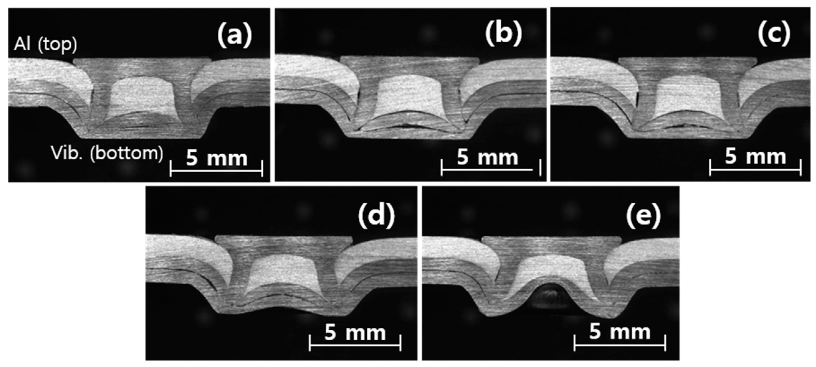
Figure 6 shows the cross-sectional views of the SPR joints of vibration-damping steel (top) to aluminum alloy (bottom) formed with different dies, as presented in Figure 3. While the cavity inside the rivet shank (or rivet cavity) was formed for the dies with a flat-bottomed cavity (types A1, A2, and A3), the rivet cavity was significantly reduced when non-flat dies (type B and C) were used due to the protruded part of the dies. The punched slug from the top vibration-damping steel embedded into the shank cavity separated in common. On the other hand, the top sheets of the joints barely separated, showing a little slipping between the outer steel sheets of top vibration-damping steel.
The rivet head gap between the rivet head edge and the upper surface of the bended top sheet in the joint represents the amount of top surface sealing. The gap increased with the increase of the die taper angle and diameter, because the die-to-rivet volume ratio (R) increased as the die taper and diameter increased, as presented in Figure 3. As described by Ma et al. [19], for R > 1, the die with the larger cavity imposed fewer constraints on the material stacks, and thus the bending curvature of the top sheet increased with increasing R and resulted in the gap increase. In the case of the not-flat dies (type B and C), the projection (or tip) of the dies did not reduce the gap. Especially for the type C die, its R was less than that of type A1 die but the gap was more than that of the type A1 die. Hence, the tip of the not-flat die was not effective for top surface sealing, but only for reducing the rivet cavity.
Figure 7 shows the measurement results of geometrical indices for the SPR joint of the vibration-damping steel (top) and Al5052-H32 (bottom) with respect to the SPR die type. As seen in the figure, the joint made from the type A1 die has the largest interlock width, and it decreases in the order of type A2, type A3, type B, and type C. The flat dies (types A1, A2, and A3) induced a larger interlock width compared with the non-flat dies (types B and C). For the flat dies, the interlock width was not only reduced by the increase of the die taper angle, but also the increase of the die diameter. The increase in both the die taper angle and die diameter contributed to the increase of the die volume in the radial direction. Consequently, the bottom sheet (Al5052-H32) was more deformed in the radial direction, leading to less interlocking between the rivet shank and lower sheet. The bottom thickness of the joints was much larger than the interlock width of the joints, due to the small penetration made by the rivet shank in the bottom sheet. For the flat die, the bottom thickness of the joints had an opposite trend with the interlock width; however, no distinct trend was observed when the bottom thickness of the non-flat die was compared with that of the flat die.
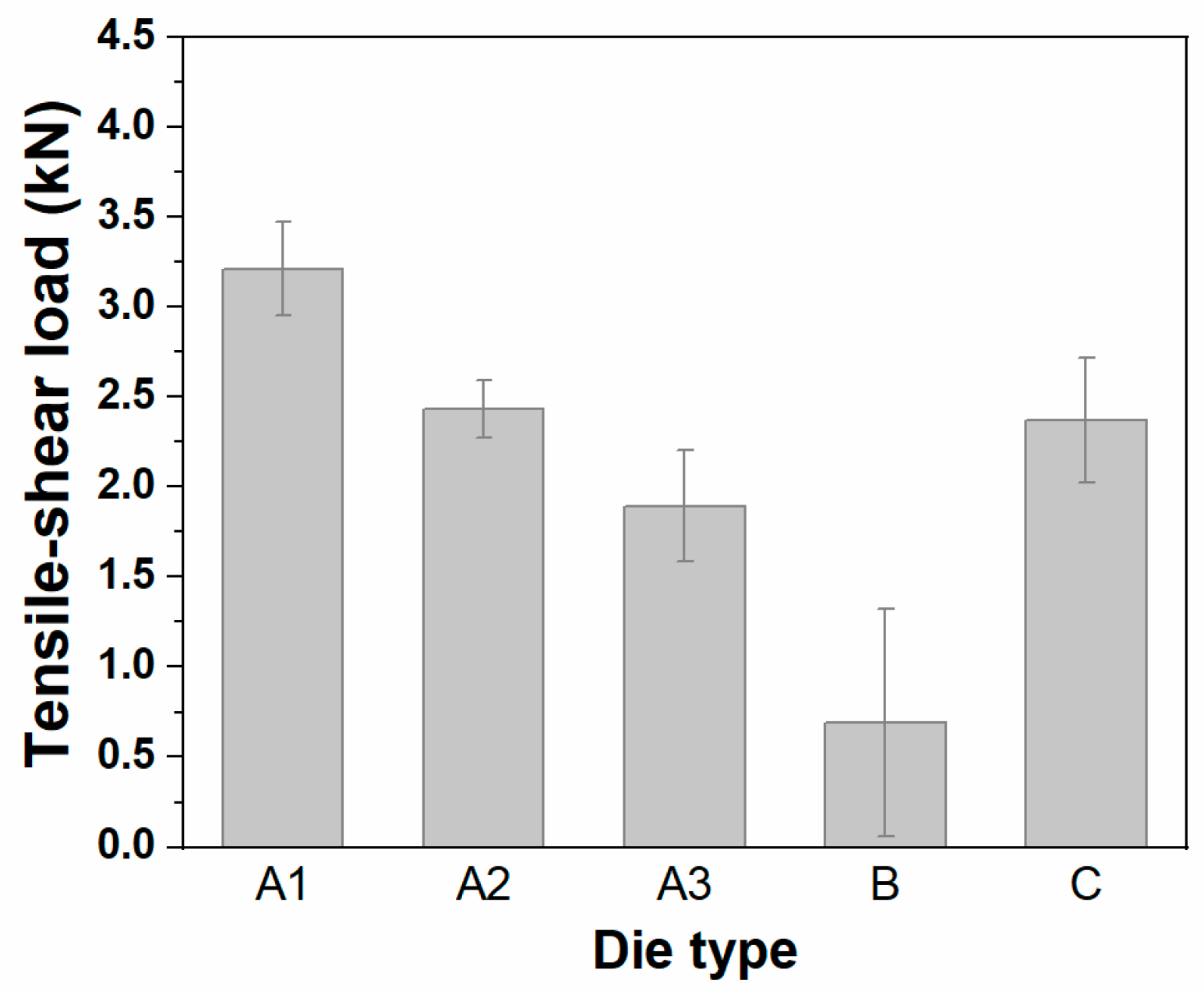
The tensile–shear load of the specimens is shown in Figure 8. The joint made from the type A1 die had the highest tensile–shear load, owing to the large interlock width, and it decreased with the decrease of the interlock width (refer to Figure 7 and Figure 8). However, the tensile–shear load of the joint formed by a type C die was relatively high, even though it had the smallest interlock width, as presented in Figure 7. This is due to the fact that the type C die had a relatively small die-to-rivet ratio (R = 1.254), which imposed more constraints on the bottom material. This may have further induced the strain hardening of the bottom sheet (Al5052-H32), contributing to the overall improvement in the joint’s mechanical performance.
The failure images in the lap shear testing of the SPR joints are presented in Figure 9. Regardless of the die type, rivet pull-outs from the bottom sheet were observed for the stack-up. Neither top sheet fracture nor rivet fracture was found for all cases. In addition, the interlocking between the rivet and bottom sheet completely failed, as presented in the figure. Thus, the rivet pull-out failures were mainly due to the small interlock widths of the joints (<0.3 mm for all cases of this study), where less than approximately one-fourth of the rivet shank was only entrapped by the bottom sheet. Consequently, the rivet was apt to be pulled out from the bottom sheet because of the weak interlocking between the rivet shank and bottom sheet. The rivet pull-out failures of the SPR joints due to the small interlock width have been reported in other studies as well [19,23,24].
3.2. SPR Joint of Aluminum Alloy (Top) and Vibration-Damping Steel (Bottom)
Figure 10 shows the cross-sectional views of SPR joints of aluminum alloy (top) to vibration-damping steel (bottom) formed with different die types, as presented in Figure 3. Different from the reversed sheet material’s stack configuration, the rivet shank in these SPR joints were fully filled with the stack materials, so no rivet cavity was formed, which is commonly reported when a ductile metal such as aluminum alloy is used as the top material [19,24,25]. The rivet penetrated through the top sheet of the bottom vibration-damping steel, but not into the bottom sheet of the vibration-damping steel. Hence, the top steel sheet of the vibration-damping steel actually sustained the mechanical interlocking for the joint as the bottom sheet. The bottom steel sheet of the vibration-damping steel increased the mechanical performance of the top steel sheet and made a bottom sealing. The two outer sheets of the vibration-damping steel were stuck to each other by the adhesive layer. The rivet head gap was hardly observed compared with the reversed stack configuration, regardless of die type.
Figure 11 shows the measured geometrical indices of the SPR joints for this material stack with respect to the SPR die type. The results show that the stack of aluminum alloy (top) to vibration-damping steel (bottom) had more interlock width than the reverse stack for all types of dies. The rivet shank cavity was fully filled with the stack material and the rivet head gap was tightly sealed because the top sheet aluminum alloy had a better formability than the top vibration-damping steel sheet for the reversed stack. As a result, more rivet shank penetrated into the bottom sheet, and thus less shank was entrapped by the top sheet. The type A1 die gave the largest interlock width, and the smallest interlock width was obtained with the type B die. The interlock widths of other joints were similar to each other, as shown in the figure. It was also observed, as is the case for the reverse material stack, that for dies with a flat-bottom shape (types A1, A2, and A3), the increase of the die taper angle, as well as die diameter, reduced the interlock, since the number of constraints on the bottom sheet reduced with increasing die cavity. The bottom thickness had a contrary trend with the interlock width for dies with a flat-bottom shape (types A1, A2, and A3); however, a clear trend of the bottom thickness was not found for the non-flat die (types B and C), whose trend was also observed in the case of the reverse material stack configuration.
The tensile–shear test results for the SPR joints of aluminum alloy (top) and vibration-damping steel (bottom) are presented in Figure 12. The results show that this material stack configuration had a greater tensile shear load than the reversed stack for all types of die. This is attributable to the overall increase of the interlock width when the vibration-damping steel was used as a bottom sheet. As for the die type dependence, the difference in the tensile–shear load of specimens was insignificant for this stack (the difference in measured tensile–shear load was 0.34 kN) compared to that of the reversed stack (the difference in measured tensile–shear load was 2.52 kN), as presented in Figure 8. This indicates that the mechanical performance of the joint using vibration-damping steel as a bottom sheet was less affected by die type than the joint using it as a top sheet. The joint made from type A1 had the highest tensile–shear load, which was the same as that of the reversed stack. For the joint configuration using vibration-damping steel as a bottom sheet, the second highest tensile–shear load was obtained with the type C die. This could be ascribed to the second highest value of the interlock width of the joint.
The failure images of the joints are shown in Figure 13. The rivet pull-out failure was observed for all specimens. As discussed in Section 3.1, these pull-out failures were due to the fact that the interlock width, which was much greater than that of the reversed stack, was still not enough to induce other failure modes such as top sheet tearing and rivet fracture.
3.3. Vibration-Damping Steel vs. SPFC590DP
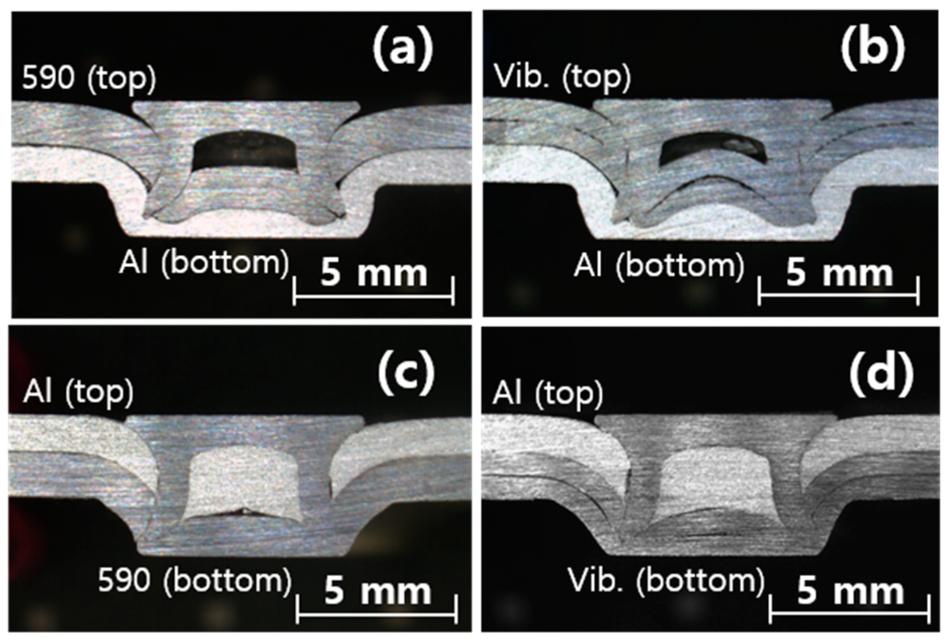
In this study, the geometrical and mechanical characteristics of the SPR joint of vibration-damping steel were compared with those of SPFC590DP (a skin material of the vibration-damping steel). The thickness of SPFC590DP was chosen to be 1.4 mm, which was the same as the sum of thicknesses (0.7 mm) of the outer sheets in the vibration-damping steel. For the comparison, SPR joints were formed with the type A1 die. In the cross-sectional images of the SPR joints in Figure 14, the stack of joining the vibration-damping steel to the aluminum alloy (Al5052-H32) as the bottom material had a smaller cavity and rivet head gap than the stack of joining SPFC590DP to the aluminum alloy. This was because the vibration-damping steel was more flexible than the solid SPFC590DP, because of the viscoelastic adhesive layer in the vibration-damping steel (refer to Figure 14a,b).
For the Al5052-H32 top–stack configuration, the rivet cavity is completely filled with ductile Al5052-H32 for both the SPR joints (refer to Figure 14c,d). However, slightly higher deformation of the vibration-damping steel is observed at the bottom–center of the joint due to the separation of the outer sheets of the vibration-damping steel.
Figure 15 shows the result of the measured geometrical indices for the SPR joints. It was found that the interlock width and bottom thickness of the SPR joint of the vibration-damping steel were almost the same as those of the joint of SPFC590DP when Al5052-H32 was used as a bottom sheet. However, when Al5052-H32 was used as a top sheet, both the interlock width and bottom thicknesses of the joint made from the vibration-damping steel were larger than those of the joint made from SPFC590DP.
The tensile–shear loads of the SPR joints of the stack configurations are presented in Figure 16. For the Al5052-H32 bottom configuration, the tensile–shear load of the joint made from SPFC590DP was 22.6% larger than that made from the vibration-damping steel, despite the interlock width of the two joints being similar. This difference (~1 kN) in the tensile–shear load of the two joints was attributable to the difference in the intrinsic mechanical properties of the base materials. The flexural rigidity of the vibration-damping steel was less than SPFC590DP, so more bending of the vibration-damping steel occurred than the SPFC590DP as the top sheet in the lap shear test, which led to inter-locking failure in the earlier stage [19,24]. However, the tensile–shear load of the joint made from the vibration-damping steel was slightly larger than that of the joint made from SPFC590DP when Al5052-H32 was used as a top sheet. This was mainly due to the larger interlock width of the joint made from the vibration-damping steel.
In this study, the mechanical performance of the SPR joint between the vibration-damping steel and Al5052-H32 was always improved when the thinner Al5052-H32 was used as a top sheet, due to the increase of the interlock width. However, for the SPR joint in the SPFC590DP and Al5052-H32, using the thicker SPFC590DP as a top sheet gave more tensile–shear load by 3.9%, despite the smaller interlock width.
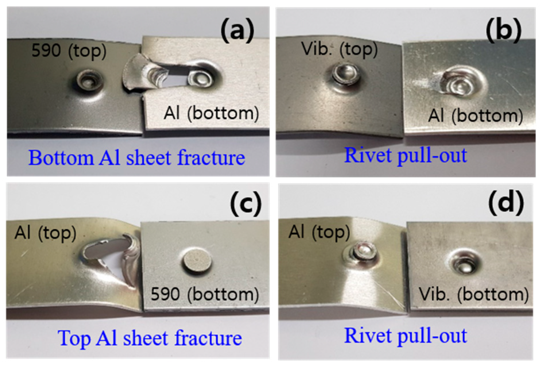
The failure images of the joints are illustrated in Figure 17. According to the figure, the joints in SPFC590DP and Al5052-H32 had the preferential fracture of the Al5052-H32 sheet, instead of showing the rivet pull-out failure, regardless of the joint configuration. The high mechanical strength of the SPFC590DP gave more solid interlocking between SPFC590DP and rivet (high resistance to bending deformation caused by the tensile–shear load), which in turn caused more stress concentration at the interlocking region between Al5052-H32 and the rivet during the tensile–shear test. This stress concentration in the Al5052-H32, with a much lower mechanical strength (nearly three times smaller) than SPFC590DP, would eventually drive it to be preferentially fractured.
4. Conclusions
In this study, the SPR joining between dissimilar materials of vibration-damping steel, SPFC590DP, and Al5052-H32 was carried out, and the mechanical performance, failure mode, and geometrical features of the joints with different die types and material stack configurations were investigated. The important conclusions of this research are as follows:
- (1)
- The SPR joint between the vibration-damping steel and Al5052-H32 showed mechanical performance similar to that between SPFC590DP and Al5052-H32. For the Al5052-H32 bottom configuration, the SPR joint of the vibration-damping steel had 22.6% lower tensile–shear load than SPFC590DP. However, it had 3.9% higher tensile–shear load than SPFC590DP when Al5052-H32 was used as a top sheet. These results suggest that the SPR technique could be a promising solution for dissimilar joining between vibration-damping steel and aluminum.
- (2)
- The SPR joints of the vibration-damping steel and Al5052-H32 with the Al5052-H32–top configuration had a consistent superior mechanical performance, mainly due to the increase of the interlock width. In addition, due to the small interlock width, all SPR joints of the vibration-damping steel and Al5052-H32 showed consistent rivet pull-out failure, regardless of the joint configuration.
- (3)
- The SPR joints of the vibration-damping steel and Al5052-H32 showed the largest tensile shear load with a flat die (a benchmark die). For the flat die, the increase of die taper angle and diameter reduced the mechanical performance of the joint, owing to the increase of the die’s volume, resulting in the smaller interlock width of the joint.
Author Contributions
CRediT authorship contribution statement. D.-H.K., project administration, supervision, conceptualization, methodology, writing—original draft, and funding acquisition. T.-E.J., investigation, formal analysis, data curation, and methodology. M.-G.K., investigation, formal analysis, data curation, and visualization. J.S., formal analysis, visualization, writing—original draft, review, and editing.
Funding
This research work was supported by the Korea Institute of Industrial Technology and the Industry Core Technology Development Program funded by the Ministry of Trade, Industry & Energy (Korea). Grant No. 10063579.
Conflicts of Interest
The authors declare no conflicts of interest.
References
- Isenstadt, A.; German, J.; Bubna, P.; Wiseman, M.; Venkatakrishnan, U.; Abbasov, L.; Guillen, P.; Moroz, N.; Richman, D.; Kolwich, G. Lightweighting Technology Development and Trends in U.S. Passenger Vehicles, International Council on Clean Transportation, Working Paper. 2016. Available online: https://theicct.org/sites/default/files/publications/ICCT_PVtech_lightweighting_wp2016-25.pdf (accessed on 26 October 2019).
- Mascarin, A.; Hannibal, T.; Raghunathan, A.; Ivanic, Z.; Francfort, J. Vehicle Lightweighting: 40% and 45% Weight Savings Analysis: Technical Cost Modeling for Vehicle Lightweighting. Available online: https://inldigitallibrary.inl.gov/sites/sti/sti/6492855.pdf (accessed on 26 October 2019).
- Aslanlar, S. The effect of nucleus size on mechanical properties in electrical resistance spot welding of sheets used in automotive industry. Mater. Des. 2006, 27, 125–131. [Google Scholar] [CrossRef]
- Zhou, K.; Yao, P. Overview of recent advances of process analysis and quality control in resistance spot welding. Mech. Syst. Signal Process. 2019, 124, 170–198. [Google Scholar] [CrossRef]
- Chen, C.; Kong, L.; Wang, M.; Haselhuhn, A.S.; Sigler, D.R.; Wang, H.P.; Carlson, B.E. The robustness of Al-steel resistance spot welding process. J. Manuf. Process. 2019, 43, 300–310. [Google Scholar] [CrossRef]
- Katayama, S. Laser welding of aluminium alloys and dissimilar metals. Weld. Int. 2004, 18, 618–625. [Google Scholar] [CrossRef]
- Assunção, E.; Quintino, L.; Miranda, R. Comparative study of laser welding in tailor blanks for the automotive industry. Int. J. Adv. Manuf. Technol. 2010, 49, 123–131. [Google Scholar] [CrossRef]
- Oladimeji, O.O.; Taban, E. Trend and innovations in laser beam welding of wrought aluminum alloys. Weld. World 2016, 60, 415–457. [Google Scholar] [CrossRef]
- Torkamany, M.; Tahamtan, S.; Sabbaghzadeh, J. Dissimilar welding of carbon steel to 5754 aluminum alloy by Nd: YAG pulsed laser. Mater. Des. 2010, 31, 458–465. [Google Scholar] [CrossRef]
- Mathieu, A.; Shabadi, R.; Deschamps, A.; Suéry, M.; Matteï, S.; Grevey, D.; Cicala, E. Dissimilar material joining using laser (aluminum to steel using zinc-based filler wire). Opt. Laser Technol. 2007, 39, 652–661. [Google Scholar] [CrossRef]
- Zhou, D.; Xu, S.; Zhang, L.; Peng, Y.; Liu, J. Microstructure, mechanical properties, and electronic simulations of steel/aluminum alloy joint during deep penetration laser welding. Int. J. Adv. Manuf. Technol. 2017, 89, 377–387. [Google Scholar] [CrossRef]
- Khoddam, S.; Tian, L.; Sapanathan, T.; Hodgson, P.D.; Zarei-Hanzaki, A. Latest Developments in Modeling and Characterization of Joining Metal Based Hybrid Materials. Adv. Eng. Mater. 2018, 20, 1800048. [Google Scholar] [CrossRef]
- Pramanik, A.; Basak, A.; Dong, Y.; Sarker, P.; Uddin, M.; Littlefair, G.; Dixit, A.; Chattopadhyaya, S. Joining of carbon fibre reinforced polymer (CFRP) composites and aluminium alloys—A review. Compos. Part A Appl. Sci. Manuf. 2017, 101, 1–29. [Google Scholar] [CrossRef]
- Huang, Z.C.; Zhou, Z.J.; Huang, W. Mechanical Behaviors of Self-Piercing Riveting Joining Dissimilar Sheets. Adv. Mater. Res. 2010, 97, 3932–3935. [Google Scholar] [CrossRef]
- Haque, R.; Durandet, Y. Investigation of self-pierce riveting (SPR) process data and specific joining events. J. Manuf. Process. 2017, 30, 148–160. [Google Scholar] [CrossRef]
- Eshtayeh, M.M.; Hrairi, M.; Mohiuddin, A.K.M. Clinching process for joining dissimilar materials: State of the art. Int. J. Adv. Manuf. Technol. 2016, 82, 179–195. [Google Scholar] [CrossRef]
- Mucha, J. The analysis of lock forming mechanism in the clinching joint. Mater. Des. 2011, 32, 4943–4954. [Google Scholar] [CrossRef]
- Hong, S.H.; Yan, F.; Sung, S.J.; Pan, J.; Su, X.; Friedman, P. Investigation of Failure Mode and Fatigue Behavior of Flow Drill Screw Joints in Lap-Shear Specimens of Aluminum 6082-T6 Sheets. SAE Int. J. Mater. Manuf. 2016, 9, 746–750. [Google Scholar] [CrossRef] [Green Version]
- Ma, Y.W.; Lou, M.; Li, Y.B.; Lin, Z.Q. Effect of rivet and die on self-piercing rivetability of AA6061-T6 and mild steel CR4 of different gauges. J. Mater. Process. Technol. 2018, 251, 282–294. [Google Scholar] [CrossRef]
- Abe, Y.; Kato, T.; Mori, K. Joinability of aluminium alloy and mild steel sheets by self piercing rivet. J. Mater. Process. Technol. 2006, 177, 417–421. [Google Scholar] [CrossRef]
- Han, L.; Chrysanthou, A.; Young, K. Mechanical behaviour of self-piercing riveted multi-layer joints under different specimen configurations. Mater. Des. 2007, 28, 2024–2033. [Google Scholar] [CrossRef]
- Wood, P.; Schley, C.; Williams, M.; Rusinek, A. A model to describe the high rate performance of self-piercing riveted joints in sheet aluminium. Mater. Des. 2011, 32, 2246–2259. [Google Scholar] [CrossRef]
- Xie, Z.; Yan, W.; Yu, C.; Mu, T.; Song, L. Improved shear strength design of cold-formed steel connection with single self-piercing rivet. Thin Walled Struct. 2018, 131, 708–717. [Google Scholar] [CrossRef]
- Jeong, T.E.; Kim, M.G.; Rhee, S.; Kam, D.H. Joint Quality Study of Self-piercing Riveted Aluminum and Steel Joints Depending on the Thickness and Strength of Base Metal. J. Weld. Join. 2019, 37, 212–219. [Google Scholar] [CrossRef]
- Lou, M.; Li, Y.; Wang, Y.; Wang, B.; Lai, X. Influence of resistance heating on self-piercing riveted dissimilar joints of AA6061-T6 and galvanized DP. J. Mater. Process. Technol. 2014, 214, 2119–2126. [Google Scholar] [CrossRef]
Figure 1.
Cross-sectional view of the vibration-damping steel plate.

Figure 2.
Engineering drawing of self-piercing rivet (SPR) rivet.

Figure 3.
Die types used for SPR process in this study.

Figure 4.
Definition of geometrical indices of the SPR joint.

Figure 5.
Schematic diagram of tensile–shear test specimen (KS B ISO 14273).

Figure 6.
Cross-sectional images for SPR joint of vibration-damping steel (top) and Al5052-H32 (bottom) with respect to SPR die type. (a) Type A1 die, (b) type A2 die, (c) type A3 die, (d) type B die, and (e) type C die.
Figure 6.
Cross-sectional images for SPR joint of vibration-damping steel (top) and Al5052-H32 (bottom) with respect to SPR die type. (a) Type A1 die, (b) type A2 die, (c) type A3 die, (d) type B die, and (e) type C die.

Figure 7.
Geometrical indices for SPR joint of vibration-damping steel (top) and Al5052-H32 (bottom) with respect to SPR die type.
Figure 7.
Geometrical indices for SPR joint of vibration-damping steel (top) and Al5052-H32 (bottom) with respect to SPR die type.

Figure 8.
Tensile–shear loads for SPR joint of vibration-damping steel (top) and Al5052-H32 (bottom) with respect to SPR die type.
Figure 8.
Tensile–shear loads for SPR joint of vibration-damping steel (top) and Al5052-H32 (bottom) with respect to SPR die type.

Figure 9.
Failure modes for SPR joint of vibration-damping steel (top) and Al5052-H32 (bottom) with respect to SPR die type. (a) Type A1 die, (b) type A2 die, (c) type A3 die, (d) type B die, and (e) type C die.
Figure 9.
Failure modes for SPR joint of vibration-damping steel (top) and Al5052-H32 (bottom) with respect to SPR die type. (a) Type A1 die, (b) type A2 die, (c) type A3 die, (d) type B die, and (e) type C die.

Figure 10.
Cross-sectional images of SPR joints of Al5052-H32 (top) and vibration-damping steel (bottom) with respect to SPR die type. (a) Type A1 die, (b) type A2 die, (c) type A3 die, (d) type B die, and (e) type C die.
Figure 10.
Cross-sectional images of SPR joints of Al5052-H32 (top) and vibration-damping steel (bottom) with respect to SPR die type. (a) Type A1 die, (b) type A2 die, (c) type A3 die, (d) type B die, and (e) type C die.

Figure 11.
Geometrical indices for SPR joint of Al5052-H32 (top) and vibration-damping steel (bottom) with respect to SPR die type.
Figure 11.
Geometrical indices for SPR joint of Al5052-H32 (top) and vibration-damping steel (bottom) with respect to SPR die type.

Figure 12.
Tensile–shear loads for SPR joint of Al5052-H32 (top) and vibration-damping steel (bottom) with respect to SPR die type.
Figure 12.
Tensile–shear loads for SPR joint of Al5052-H32 (top) and vibration-damping steel (bottom) with respect to SPR die type.

Figure 13.
Failure modes for SPR joint of Al5052-H32 (top) and vibration-damping steel (bottom) with respect to SPR die type. (a) Type A1 die, (b) type A2 die, (c) type A3 die, (d) type B die, and (e) type C die.
Figure 13.
Failure modes for SPR joint of Al5052-H32 (top) and vibration-damping steel (bottom) with respect to SPR die type. (a) Type A1 die, (b) type A2 die, (c) type A3 die, (d) type B die, and (e) type C die.

Figure 14.
Comparison of cross-sectional images of SPR joint (fabricated by type A1 die) for different stack-up combinations. (a) SPFC590DP (top) and Al5052-H32 (bottom), (b) vibration-damping steel (top) and Al5052-H32 (bottom), (c) Al5052-H32 (top) and SPFC590DP (bottom), and (d) Al5052-H32 (top) and vibration-damping steel (bottom).

Figure 15.
Comparison of geometrical indices of SPR joints (fabricated by type A1 die) for different stack-up combinations.
Figure 15.
Comparison of geometrical indices of SPR joints (fabricated by type A1 die) for different stack-up combinations.

Figure 16.
Comparison of tensile–shear loads of SPR joint (fabricated by type A1 die) for different stack-up combinations.
Figure 16.
Comparison of tensile–shear loads of SPR joint (fabricated by type A1 die) for different stack-up combinations.

Figure 17.
Comparison of failure modes of the SPR joint (fabricated by type A1 die) for different stack-up combinations. (a) SPFC590DP (top) and Al5052-H32 (bottom), (b) vibration-damping steel (top) and Al5052-H32 (bottom), (c) Al5052-H32 (top) and SPFC590DP (bottom), and (d) Al5052-H32 (top) and vibration-damping steel (bottom).


Table 1.
Tensile strengths and thicknesses of the materials used in this study.
| Sheet Material | Ultimate Tensile Strength (MPa) | Elongation (%) | Thickness (mm) |
|---|---|---|---|
| Vibration-damping steel | 618 | 17 | 1.5 |
| SPFC590DP | 609 | 25 | 1.4 |
| Al5052-H32 | 233 | 12 | 1.2 |
© 2019 by the authors. Licensee MDPI, Basel, Switzerland. This article is an open access article distributed under the terms and conditions of the Creative Commons Attribution (CC BY) license (http://creativecommons.org/licenses/by/4.0/).
Share and Cite
MDPI and ACS Style
Kam, D.-H.; Jeong, T.-E.; Kim, M.-G.; Shin, J. Self-Piercing Riveted Joint of Vibration-Damping Steel and Aluminum Alloy. Appl. Sci. 2019, 9, 4575. https://0-doi-org.brum.beds.ac.uk/10.3390/app9214575
AMA Style
Kam D-H, Jeong T-E, Kim M-G, Shin J. Self-Piercing Riveted Joint of Vibration-Damping Steel and Aluminum Alloy. Applied Sciences. 2019; 9(21):4575. https://0-doi-org.brum.beds.ac.uk/10.3390/app9214575
Chicago/Turabian StyleKam, Dong-Hyuck, Taek-Eon Jeong, Min-Gyu Kim, and Joonghan Shin. 2019. "Self-Piercing Riveted Joint of Vibration-Damping Steel and Aluminum Alloy" Applied Sciences 9, no. 21: 4575. https://0-doi-org.brum.beds.ac.uk/10.3390/app9214575
Note that from the first issue of 2016, this journal uses article numbers instead of page numbers. See further details here.