Review

Removal of Hydrogen Sulfide with Metal Oxides in Packed Bed Reactors—A Review from a Modeling Perspective with Practical Implications

by
Ramiar Sadegh-Vaziri
and
Matthaus U. Babler
*
Department of Chemical Engineering, KTH Royal Institute of Technology, SE-10044 Stockholm, Sweden
*
Author to whom correspondence should be addressed.
Submission received: 3 October 2019 / Revised: 20 November 2019 / Accepted: 30 November 2019 / Published: 5 December 2019
(This article belongs to the Special Issue Biomass Energy and Biomass as a Clean Renewable Fuel)

Abstract

:
Sulfur, and in particular, H 2 S removal is of significant importance in gas cleaning processes in different applications, including biogas production and biomass gasification. H 2 S removal with metal oxides is one of the most viable alternatives to achieve deep desulfurization. This process is usually conducted in a packed bed configuration in order to provide a high solid surface area in contact with the gas stream per unit of volume. The operating temperature of the process could be as low as room temperature, which is the case in biogas production plants or as high as 900 C suitable for gasification processes. Depending on the operating temperature and the cleaning requirement, different metal oxides can be used including oxides of Ca, Fe, Cu, Mn and Zn. In this review, the criteria for the design and scale-up of a packed bed units are reviewed and simple relations allowing for quick assessment of process designs and experimental data are presented. Furthermore, modeling methods for the numerical simulation of a packed bed adsorber are discussed.

1. Introduction

H 2 S is a colorless gas that is denser than air [1]. It is flammable [2], toxic [3] and highly corrosive [4], with an unpleasant smell of rotten eggs [5]. H 2 S needs to be removed from fuels since it converts to SO 2 during combustion and causes acid rains when released into the environment [6]. Because of these properties, H 2 S removal is a crucial step in gas cleaning and finds application in different industries including coal and biomass gasification [7,8], biogas production [9] wastewater treatment, food processing and production and other fuel production processes [10]. In most of these applications the concentration of H 2 S is magentarelatively low, i.e., well below 1 vol%.
Absorption-based methods to remove H 2 S are used in different reactor configurations, such as packed columns or spray towers. The most common solver is water which, however, cannot remove H 2 S to low concentrations due to the low solubility of H 2 S in water, with the Henry’s constant of about 10 3 mol/(m 3 Pa) at room temperature [11]. Most of the available solvents that have high solubilities for H 2 S require extreme operating conditions, i.e., high pressures and/or low temperatures, which translates into high operating costs [12]. Due to this, absorption based methods, although high in technological readiness, are less favorable for the treatment of diluted gas streams when compared to other technologies.
In particular, regarding adsorption based technologies, we find activated carbon as the most common adsorbent available but it has a very low sulfur removal capacity [13]. The adsorption capacity can be enhanced by impregnating the activated carbon with metals, resulting in composite sorbents in which the metal is present in the form of nano-scopic oxide particles [14,15,16]. Bio-chars containing different metals, including Ca, Fe and Mn, where found to have similar sulfur removal capacities as composite active carbon materials [17,18,19]. This is especially interesting, as bio-chars are obtained from waste materials. Due to the low cost of feedstock and high removal capacities [20], these materials have the potential to be viable sorbents. However, there is limited testing of carbonaceous sorbent materials for high temperature applications.
Membrane technology with facilitated transport properties is another alternative to remove H 2 S. However, the complications of operating a membrane process at optimum conditions still makes it an unfavorable alternative at the current development stage [13]. H 2 S can be removed by precipitation techniques as well. A solution containing FeCl 2 , FeCl 3 or FeSO 4 can be used to precipitate the sulfur in the form of FeS. Technical complications of operating a continuous process based on this principle aside, the final concentration of H 2 S after treatment remains around 100 ppm which is still high for most applications [21,22].
Biological processes degrade H 2 S to elemental sulfur have shown a high potential at pilot and demonstration scale plants. Despite being environmentally friendly and economically advantageous, there are still challenges to be addressed [23,24]. Biological removal of H 2 S can use both photo-trophic and chemo-trophic bacteria to bio-oxidize hydrogen sulfide. The requirement of a light source for photo-trophic bacteria is the main constraint for adapting the technology to the industrial scale [23]. Chemo-trophic bacteria require an oxygen or nitrite source, and if the amount is not at the optimum level, H 2 S tends to convert to sulphates which is not desired [25,26].
Using metal sorbents to remove H 2 S from diluted gas streams is a common practice nowadays [27]. The active compound of the sorbent is a metal oxide that reacts with H 2 S to trap the sulfur in the form of solid metal sulfide according to:
H 2 S ( g ) + γ MO ( s ) H 2 O ( g ) + γ MS ( s )
where γ is the stoichiometry coefficients, MO is the metal oxide and MS is the produced metal sulfide. Notice that MO and MS in the notation used here do not strictly refer to stoichiometric compounds, i.e., MO may stand for e.g., Fe 2 O 3 . Depending on the cleaning requirement and the desired operating temperature, there are different metal oxides that are suitable to be used in reaction (Equation (1)). The efficiency, simplicity and relatively low cost of metal oxide based sorption methods have given the method ”an edge” over other possible alternatives [28].
This review presents an overview of the current state of development of metal oxide sorption processes for the removal of H 2 S in packed bed reactors. Next to discussing the key results from the literature we specifically discuss design criteria for packed bed reactors, present guidelines for the selection of a suitable metal oxide and review modelling strategies for describing and analyzing H 2 S removal in a packed bed. The latter is complemented by a set of mathematical approximations that allow for a quick assessment of process designs and experimental data and their feasibility. There are several review papers on syngas and biogas cleaning that discuss H 2 S removal methods [8,13,19,29,30,31,32,33,34,35], however, only few discuss the removal by using unsupported metal oxides suitable for high temperature applications [27,36,37]. The presents paper adds an additional dimension to these works by reviewing the metal oxide sorption process from the viewpoint of process design and process modeling.

2. Process Design

Considering a process for the removal of H 2 S employing reaction (Equation (
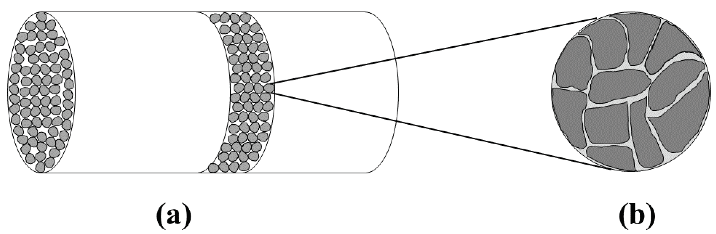
1)), two characteristic length scales become apparent: The reactor scale which is typically of the order of few centimeters to meters, and the pellet scale which is typically of the order of few hundred of micrometers up to centimeters. Figure 1 shows these two scales schematically for a packed bed reactor. The gas stream containing H 2 S is introduced into the reactor where it gets in contact with the pellets that contain the metal oxide. The metal oxide reacts with H 2 S which binds the sulfur in form of solid metal sulfide. Transport phenomena taking place outside the pellets, i.e., the mass transfer of the gaseous reactant from the bulk of the fluid to the pellet surface, is commonly referred to as external mass transfer. Moreover, the transport phenomena taking place inside the pellet include internal mass transfer, i.e., the diffusion of the gaseous reactant to the reaction sites, and the reaction itself. The two scales are typically treated as being separable, i.e., phenomena on the pellet scale are often studied in simpler set-ups, e.g., by placing a pellet into a well mixed atmosphere whose H 2 S concentration is kept at a constant value. [38,39].

2.1. Reactor Scale

There are three common reactor configurations for conducting reaction (Equation (1)): entrained flow reactor [40], fluidized reactor [41] and packed bed reactor [7]. In an entrained flow reactor, the sorbent particles are immersed into the gas stream which carries them through the reactor. Thus, the residence time of the gas and the sorbent in the reactor are of a similar order of magnitude. In a packed bed reactor, the gas stream flows through the reactor while the sorbent particles remain in the reactor. The residence time of the sorbent is considerably larger than that of gas. Hence, from the viewpoint of the solid sorbent the packed bed reactor resembles a batch reactor. A fluidized bed reactor lies in between these two extremes and, depending on the operating mode, from the viewpoint of the solid sorbent the reactor resembles a well mixed continuous reactor or a batch reactor. The parameter that can be used to characterize the different reactor configurations is the particle volume fraction ϕ , that relates to the bed porosity ε b as follows:
ϕ = Total   volume   of   solid   particles Total   volume   of   reactor = 1 ε b .
The entrained flow reactor has the lowest solid volume fraction while the packed bed reactor has the highest solid volume fraction among the three reactor configurations ( ϕ > 40 % ) [42].
There are different empirical correlations to predict the bed porosity for a packed bed reactor. A simple correlation with acceptable accuracy is given by Benyahia and O’Neill [43]:
ε b = A d 0 / d p + C 2 + B
where d p is the equivalent sphere diameter of the particles, d 0 is the reactor diameter and A, B and C are empirical parameters. Table 1 gives these parameters for common particles shapes. Notice that the first term on the right hand side (rhs) of Equation (3) represents a correction for the case where the particle size is comparable to the reactor diameter; for d p d 0 the first term vanishes and the bed porosity becomes a constant.
Important parameters in choosing the reactor configuration are pressure drop, attrition of particles and contact surface. In this specific case, the available contact-surface between the solid particles and the fluid is of great importance since the kinetics of the removal reaction is not very fast and more importantly a high level of sulfur removal is often required. Among the three reactor configurations, the packed bed reactor provides the largest contact surface area for a fixed reactor volume. This is one of the reasons why the packed bed is the reactor of choice in most applications.
To estimate the pressure drop in a packed bed reactor Ergun equation is used, which reads as [44]:
Δ p L = 150 ( 1 ε b ) 2 ε b 3 μ g u g Φ d p 2 + 1.75 ( 1 ε b ) ε b 3 ρ g u g 2 Φ d p
where Δ p / L is the pressure drop per unit length, u g is the superficial gas velocity, Φ is the particle sphericity, ρ g is the density of the gas mixture and μ g is the viscosity of the gas mixture. Expressions for estimating ρ g and μ g for a gas mixture are given in Appendix A. The Ergun equation accounts for the different flow regimes, i.e., the first term on the rhs of Equation (4) is dominant when the flow is laminar while the second term is dominant when the flow is turbulent.

2.2. Pellet Scale

The pellet size and pellet porosity are the main properties that affect the removal process on the scale of the pellet. Pellet porosity directly affects the intra-pellet diffusion [45]. In order to improve the intra-pellet diffusion, it is more favorable to make pellets with high porosity without sacrificing the mechanical durability. Pellet size also affects the bed porosity and the pressure drop as described by Equations (3) and (4), respectively. Moreover, the pellet size affects the characteristic time of diffusion which means that smaller pellets require shorter diffusion time [46]. However, small pellets in a packed bed lead to high pressure drop. Hence, finding the optimum size of the pellets, that are not too small to cause high pressure drop and not too large that lead to poor diffusion through the pellet, turns into an optimization problem with the three main controlling factors, namely, characteristic time of diffusion through the pellet, bed porosity and bed pressure drop.

2.3. Operating Conditions

The reaction (Equation (1)) was tested at different reactor pressures, ranging from 1 to 20 atm. The observations show that increasing the reactor pressure adversely affects the rate of conversion [38,47,48]. This is explained by recalling that molecular diffusivity is inversely proportional to pressure, i.e., D M P 1 [44]. Hence, the mass transfer decreases as the pressure increases. Notice that the effect of pressure on the metal oxide conversion was investigated by keeping the partial pressure of the gaseous reactant constant, i.e., the percentage of H 2 S in the gas phase was gradually lowered as the pressure was increased such that the effects of a changing reactant concentration could be eliminated from the experiments. Hence, it is more favorable to run the removal process at atmospheric condition rather than pressurized.
Regarding the operating temperature, despite the common perception that metal oxides are used only at elevated temperatures [7,28,49,50,51,52], there are several works that show that certain metal oxides can remove H 2 S to ppm levels even at room temperature [53,54,55,56]. The operating temperature of H 2 S removal with metal oxides can be anywhere between 25 and 1100 C. The reaction (Equation (1)) is exothermic which means that at elevated temperature the equilibrium is shifted to the left. This implies that under thermodynamic control the higher the temperature, the higher the outlet concentration of H 2 S, i.e., less efficient removal. However, both the reaction kinetic and diffusion can benefit from elevated temperatures. Depending on the operating temperature, different metal oxides can be suitable for the purpose. This will be further discussed in Section 4.

3. Challenges and Limitations

The removal of H 2 S by metal oxides in a packed bed configuration is an established technology. However, some challenges still remain. In regard to practical applications, these are, in particular, the regeneration of the sorbent and the presence of other compounds in the gas feed. It is difficult to ensure that the sulfur removal capacity of the sorbent does not decline during desulfurization–regeneration cycles. Morphological changes and fusion of particles into each other are among the main reasons for incomplete regeneration [57,58,59]. Also, other compounds in the gas phase can dramatically change the removal efficiency [36]. This can be due to a shift in the equilibrium of the sulfidation reaction (Equation (1)) towards the reactants in the case of wet gas streams, deposition of materials and coking of the sorbent in the case of the feed stream containing tars and particulates and adsorption of foreign species onto the sorbent surfaces.

3.1. Particle Fusion

The metal sulfides that form during desulfurization has a larger molar volume than the original metal oxides which means that the metal oxide particles grow in size during sulfidation [60]. In a packed bed where the neighboring metal oxide particles are in contact with each other, there is not enough free space in the proximity of the particles, such that the particles tend to fuse together as they go through the sulfidation process (see Figure 2a) [61].
A possible solution to avoid such a problem is to make the bed porous enough that there is sufficient free space for the particles to grow. From Equation (3), it is clear that the minimum value of bed porosity is equal to B. Let us consider a packed bed of metal oxides with a porosity of ε b filled with pellets that have a porosity of ε p . Assuming that the fusion of particles during the sulfidation process reduces the pellet porosity to zero and the bed porosity to B, we can derive a condition for the minimum initial bed porosity under which fusion of particles is less likely:
ε b ( B ε p ) + ρ p G ( 1 ε p ) + ρ p G ; G = x i ρ i , o ρ i , o M i , s ρ i , s M i , o 1
where ρ p is the pellet density defined in Equation (A1) and G is the total volume expansion per unit mass of the sorbent. The subscriptions o and s refer to oxide and sulfide form of metal i in the sorbent, respectively.
However, for a packed bed of pure metal oxides, Equation (5) predicts very large porosity values that are not feasible in a packed bed configuration. Another possible solution for preventing the fusion of pellets in such cases is to add inert materials in the packing [62]. This could be either inside the pellets or simply by adding particles that are made of inert material in the packing matrix as shown in Figure 2b. γ -Al 2 O 3 is an example of a suitable material to be used as inert [61], especially with recent developments to synthesize it from waste materials [63]. In this case, the main question to answer is how much inert is required to avoid the fusion. Similar to the previous case, it is assumed that during sulfidation, pellet porosity goes to zero and the bed porosity decreases to a value that is equal to B. This leads to an estimation for the minimum mass fraction of inert to suppress fusion of particles inside the packed bed:
x inert ρ inert ( 1 ε p ) ( 1 ε b ) G ( ε b B ) + ε p ( 1 ε b ) x i ρ i , o
where x inert is the mass fraction of the inert material and ρ inert is the density of it.

3.2. Sorbent Utilization

Low sorbent utilization is one of the main issues when operating a packed bed of metal oxide, in particular when using regenerated sorbents [59]. The sorbent utilization can be estimated from the breakthrough curve. A breakthrough curve of a packed bed shows the outlet concentration of the reactor as a function of time. A schematic of a breakthrough curve is shown in Figure 3a. Although simple in concept, breakthrough curves carry a lot of information about the various phenomena taking place in the packed bed.
The breakthrough time τ b is defined as the time at which the concentration of H 2 S in the outlet stream of the reactor reaches a predefined threshold value. In experiments, the latter is typically taken close to the detection limit. The theoretical maximum breakthrough time, denoted by τ 2 in Figure 3, is calculated by assuming full utilization of the sorbent. Considering a sorbent that consists of several different metal oxides, the time for full sorbent utilization reads as:
τ 2 = m s Q C 0 i x i γ i M i = τ 0 ( 1 ε b ) ρ p C 0 i x i γ i M i
where m s is the total mass of sorbent in the packed bed, x i is the mass fraction of metal oxide i in the sorbent, M i is the molecular weight of metal oxide i, ρ p is the pellet density (see Equation (A1) in Appendix A), ε b is the bed porosity, Q is the volumetric flow rate of the gas stream and C 0 is the concentration of H 2 S in the inlet stream. Moreover, τ 0 = V / Q is the superstitial residence time, where V is the volume of the empty reactor (i.e., the reactor in the absence of sorbent).
The full sorbent utilization time τ 2 given by Equation (7) together with the breakthrough data allows for calculating the removal capacity, defined as the ratio of the actual amount of H 2 S that is removed divided by the maximum amount that can be removed:
ζ = 1 τ 2 0 1 C ( t ) C 0 d t
where C ( t ) is the reactor outlet concentration. The integral in Equation (8) is proportional to the amount of H 2 S that is removed by the packed bed. In graphical terms, it corresponds to the area above the breakthrough curve as indicated by the hatched area in Figure 3a. Sometimes, C ( t ) for large t has to be extrapolated or modelled as experiments are often terminated soon after H 2 S is detected at the reactor outlet. Reasons for a low removal capacity can be blockage of sorbent due to deposition of other material, blockage of pores or inactivation of sorbent due to reduction of the metal oxide.
The time for full sorbent utilization presents an upper bound to the breakthrough time τ b . This motivates to define a removal efficiency of a packed bed as:
η = τ b / τ 2 .
Compared to the removal capacity, the removal efficiency defined in Equation (9) can readily be deduced from breakthrough curves that are terminated soon after breakthrough. Notice that in general, the removal efficiency is different than the removal capacity. For a practical assessment of the sorbent utilization, the removal efficiency is of higher relevance.
Another characteristic time that helps for the interpretation of breakthrough data can be derived by considering the onset of the sulfidation reaction. Inspired by the work of Babé et al. [64] we consider the early stages of the reaction where only the sorbent surface is affected while the metal oxide in the inside of the sorbent particles remains untouched, i.e., the reaction first consumes the metal oxide on the surface before proceeding towards the inside of the sorbent particles. Estimating the thickness of the first layer of the metal oxide by the largest dimension of the crystal unit cell [64], the characteristic time for surface utilization for a sorbent consisting of several metal oxides reads as:
τ 1 = τ 0 ( 1 ε b ) ρ p S C 0 i a i x i ρ i γ i M i
where S is the specific surface area of the sorbent, a i is the lattice constant of metal oxide i, ρ i is the density of the (pure) metal oxide i and M i is the molecular weight of metal oxide i.
Comparing the time scales τ 1 with the breakthrough time τ b allows for better understanding the dynamics of the processes that take place in the packed bed. On the one hand, a breakthrough time smaller than τ 1 is an indication that the reaction is too slow. In order to enhance the sorbent utilization we have to increase the contact time between the gas and the sorbent and improve the mass transfer. On the other hand, a breakthrough time slightly larger than τ 1 is an indication that the sulfidation reaction does not proceed beyond the surface of the sorbent. In order to enhance to sorbent utilization we may need to reduce the particle size or to enhance reactant migration in the sorbent material.

4. Selecting a Suitable Metal Oxide

The literature discusses several metal oxides for the removal of H 2 S [27]. However, depending on the operating temperature only a few may turn out to be suitable. This section presents criteria for selecting a suitable metal oxide and examines the possible candidates according to the presented criteria. The selection criteria are [30] (1) removal efficiency, (2) sorbent durability and (3) regenerability and cost of sorbent.

4.1. Removal Efficiency

The reaction (Equation (1)) has a high equilibrium constant which means the forward reaction is favorable (i.e., removal of H 2 S). The equilibrium constant for reaction (Equation (1)) is defined as K = [ H 2 O ] / [ H 2 S ] and obeys the thermodynamic relation:
K = exp Δ G R T
where Δ G is the standard Gibbs free energy change of reaction (Equation (1)), T is the temperature and R is the gas constant. Table 2 gives Δ G for a few common metal oxides undergoing reaction (Equation (1)). The values given in Table 2 were calculated from the Gibbs free energy of formation of the reactants and the products, that can be found in [65]. Notice that reaction (Equation (1)) is exothermic. Hence, with increasing temperature the equilibrium constant decreases and the equilibrium becomes less favorable for the metal sulfide.
In addition to the equilibrium, there always exist kinetic limitations that prevent reactions from reaching equilibrium in a given reactor. The intrinsic reaction rate (i.e., the reaction rate without transport limitations) of reaction (Equation (1)) is commonly expressed as:
r = k s C H 2 S n
where r is the reaction rate defined as the rate of consumption of H 2 S per unit surface area of sorbent, k s is the intrinsic rate function, C H 2 S n is the concentration of H 2 S at the surface of the sorbent and n is the reaction order. In order to decouple the effects of binders added to the sorbent some authors write the intrinsic reaction rate as [50,66]:
r = k s C MO C H 2 S n
where C MO is the molar concentration of the metal oxide in the solid sorbent.
The reaction rate is typically measured by placing a small amount of sorbent in powder form in a gravimetric chamber whose atmosphere is kept at a constant H 2 S concentration, i.e., by continuously flushing the chamber with a gas stream containing a defined amount of H 2 S. The reaction rate is then deduced from the increase in solid weight over time. Using such an approach, most studies found the reaction (Equation (1)) to be of the first order with respect to H 2 S [48,50,51,66,67,68,69,70,71,72]. An exception is copper-based sorbents that showed a reaction order smaller than one [72,73]. For all sorbents, the rate function k s (and k s ) are found to follow Arrhenius law:
k s = k 0 exp E a R T
where k 0 is the kinetic prefactor and E a is the activation energy.
Table 3 gives an overview of the reaction rate for different metal oxides together with the temperature range over which the reaction rate was measured and the method that was used to determine the kinetic parameters. In cases where the reaction rate is reported in the form of Equation (13) we estimated C MO from the molar density of the solid sorbent [49] or from the weight fraction of MO and the true sorbent density [66]. Also, in cases where the experimental data was evaluated using the grain model (see Section 5) we estimated the grain radius as R g = 3 / ( S ρ ) , [51,67] where S is the specific surface area and ρ is the sorbent density (see Equation (A1)).
The reported kinetic prefactors show considerable variation, even among the same metal oxides. This is in part due to the different methods used for evaluating the experimental data. Also, we notice that except in the case of calcium-based sorbents, the activation energies are relatively small. On the one hand, this may hint to an adsorption–desorption mechanism accompanying the sulfidation reaction [67]. On the other hand, the low activation energies may also be caused by “pollution” of the measured reaction rate by transport phenomena: Likewise to the reaction rate function; transport coefficients also increase with temperature, although to a much lesser extent. For instance, molecular diffusivity of gases follow D M T 1.75 / P while Knudsen diffusivity follows D k T 0.5 [44]. Transport limitations might become relevant at high temperature. The weaker increase of the transport coefficient with temperature compared to the (intrinsic) reaction rate might cause a reduction of the measured activation energy.
Taking together the considerations on the equilibrium and on the kinetics, it can be seen that the kinetics benefits from increasing the temperature while the equilibrium becomes less favorable. Hence, the upper bound for the operating temperature for a given metal oxide is determined by the equilibrium while the lower bound is controlled by kinetic limitations [74]. Specifically, from the equilibrium data and the specified amount of H 2 S removal, the maximum operating temperature for a metal oxide is derived from Equation (11) as:
T max Δ G R ln C H 2 S , C H 2 O , 0 + γ ( C H 2 S , 0 C H 2 S , ) 1
where C H 2 S , 0 and C H 2 O , 0 are the inlet (or initial) concentrations of H 2 S and H 2 O, respectively (if the inlet stream does not contain any steam C H 2 O , 0 = 0 ), and C H 2 S , is the desired concentration of H 2 S after the removal is completed, i.e., the concentration after the gas has passed the packed bed before breakthrough. Similarly, the minimum operating temperature is estimated treating reaction (Equation (1)) as an irreversible reaction taking place in a well mixed continuous reactor. The resulting minimum temperature reads as:
T min E a R ln C H 2 S , ( C H 2 S , 0 C H 2 S , ) τ k 0 1
where τ is the residence time of the reactor. Notice that Equation (16) is derived by assuming the intrinsic reaction to be the rate limiting step which is valid for small (micrometer sized) sorbent particles in the early stages of the removal process. For larger sorbent particles transport limitations can become dominant even for low temperatures. In this case, transport phenomena need to be accounted for in the estimate of the minimum operating temperature. Also, we note that T min and T max are approximated based on the assumption that the metal oxides are stable and only participate in the sulfidation reaction (Equation (1)).

4.2. Durability

Sorbents require a high mechanical and chemical strength such that they can sustain high operating hours. The main mechanical strength issue with metal oxide sorbents is attrition which is more significant in fluidized bed reactors compared with fixed beds reactors [75]. Also, some metal oxides experience sintering at high temperatures which leads to changes in the surface and pore structure [76]. Such changes can have a significant impact on the performance of the sorbent. Also, compounds other than H 2 S contained in the gas stream can interact with the solid oxide and affect the removal efficiency of the sorbent [77], so it is important that the metal oxide does not extensively participate in other reactions rather than reaction (Equation (1)). The most common solution to increase the chemical and mechanical resistance of the sorbent is to mix or dope it with other compounds such as titanium [61,78].
Table 4 presents an assessment of durability issues for different metal oxide together with remediation strategies. The metal oxides in Table 4 all have a favorable equilibrium and show reasonable fast kinetics.

4.3. Cost and Regenerability

Metal oxide sorbents are primarily used for H 2 S removal from diluted streams. In the form so called guard beds they present own-standing units that are easily integrated into a process. In such applications regeneration of the sorbent is usually not considered as the spent bed is simply replaced once the sorbent saturated. This is typically the case for calcium based sorbents and, to a lesser extent, iron based sorbents that are relatively cheap such that the issue of regeneration loses significance and fresh sorbent is re-supplied when needed [110].
However, regeneration of sorbent gains importance when the fresh sorbent is costly to supply and prepare or in operations with multiple beds that cycle between removal and regeneration. Regeneration is essentially the reversal of the sulfidation reaction, i.e., the conversion of the metal sulfide to the metal oxide. The gas that is formed in the regeneration step typically contains sulfur in the form of SO 2 which is then processed further using, e.g., the Claus process that separates sulfur and stores it in form of elemental sulfur or sulfuric acid [12]. Regeneration usually takes place under extreme operating conditions, i.e., high pressure and temperature. Regeneration agents include air, oxygen or steam to which SO 2 or CO 2 is added. Table 5 gives an overview of previous works on regeneration of used metal oxides, including operating conditions and regeneration agents that were employed. The number of cycles with little to no significant drop in the sorbent capacity is also reported in Table 5.
The critical aspect of regeneration is the preservation of the removal efficiency of the sorbent. Changes in surface and pore structure during repeated sulfidation–regeneration cycles can lead to a loss of specific surface area and pore blockage [80] which in turn results in incomplete regeneration and eventually a reduction of the sulfur removal capacity. A common issue with the regeneration of sorbents for H 2 S removal is that during the sulfidation process, the metal oxide particles are fused together. This is due to the higher molar volume of the metal sulfide compared to the metal oxide. This means that in the sulfidation process, the particles slightly grow in size and some neighboring particles might squeeze into each other which results in the fusion of the particles, as schematically shown in Figure 2b. This limits the available contact surface and hinders the regenerating agents to reach to some parts of the spent sorbent, resulting in an incomplete regeneration. This issue is usually fixed by mixing the sorbent with an inert solid that does not react during sulfidation. In this way the increase of the solid volume is reduced and so the possibility of fusion of particles is lowered.

5. Modeling of Solid–Gas Reactions in Packed Beds

In this section, modeling methods to simulate the removal of H 2 S from a diluted gas stream by using a packed bed of metal oxides is discussed. The bed is filled with pellets that contain metal oxides. As the gas stream passes through the packed bed, H 2 S transfers from the bulk of the fluid to the surface of the pellets. H 2 S then diffuses through the pellets to reach the metal oxides (MO) where it finally reacts with them according to reaction (Equation (1)). At operating temperatures higher than 100 C, the products of the sulfidation reaction (Equation (1)) are water vapor and metal sulfide (MS). The water vapor transfers back to the fluid bulk, while the metal sulfide substitutes the metal oxide in the solid phase. The transfer of water vapor to the fluid bulk has negligible effects on the overall rate of H 2 S removal and therefore is usually not included in the modeling process. Moreover, despite the exothermic nature of the sulfidation reaction, temperature changes are negligible for the low H 2 S concentrations typically experienced in sorption processes employing metal oxides. Also, the equilibrium of reaction (Equation (1)) at the operating temperature is to the right for most of the metal oxides such that reaction (Equation (1)) can be considered irreversible.
Consider a packed bed of fresh sorbent of length L to which a stream containing H 2 S at a concentration C 0 is fed. Assuming a constant gas flow, a mass balance for the bulk fluid concentration reads as:
C t + u i n t C x = E 2 C x 2 ν a p N p B . C . : C 0 = C E u i n t C x at x = 0 C x = 0 at x = L I . C . : C = 0
where C is the concentration of H 2 S in the bulk fluid, u i n t = Q / ( ε b A ) is the interstitial velocity of the gas stream, with Q denoting the volumetric gas flow rate, ε b is the bed porosity and A is the cross-sectional area of the packed bed, E is the axial dispersion in the bed, ν = ( 1 ε b ) / ε b is the solidity of the packed bed, a p is the specific surface area per unit volume of the pellets (for spherical pellets with diameter d p we have a p = 6 / d p ) and N p is the flux of H 2 S from the bulk fluid to the pellets. Boundary conditions (B.C.) are formulated as Danckwerts boundary conditions [44], while initial conditions (I.C.) assume the bed is initially free of H 2 S.
The flux N p depends on the H 2 S concentration at the pellet surface C p , s . In order to find C p , s , we revisit the transport phenomena occurring on the pellet surface and its vicinity. H 2 S transfers from the bulk fluid to the pellet surface, from where it diffuses into the pellet. Assuming no accumulation of H 2 S on the pellet surface, the following expression is derived:
C p , s = C N p k g
where k g is the external mass transfer coefficient that is estimated from an appropriate Sherwood-correlation [42,115], while N p is estimated by realizing the phenomena occurring inside the pellets. In the literature, there are three major types of models to describe the pellet dynamics. In the following, we present these models and how they are used to estimate N p .

5.1. Lumped Model

We begin by investigating a simple lumped model to estimate the flux of H 2 S into the pellets. The specific lumped model that we present here is referred to in the literature as deactivation model [98]. According to this model, consumption and structural changes of the sorbent are lumped in a single parameter, namely the activation coefficient α which is defined as α = 1 X , where X is the solid conversion. The flux of H 2 S into the pellets N p is determined from:
N p = α k s C p , s
where k s is the surface reaction rate function that may differ from the intrinsic rate function presented in Section 4. knowing N p , the gas concentration on the pellet surface is obtained from Equation (18) as C p , s = k g C / ( k g + α k s ) . The rate of decay of sorbent activity is described by a power law according to [98]:
α t = k α C p , s n α m I . C . : α = 1
where k α is the deactivation rate constant, and n and m are the deactivation exponents which are usually predetermined at fixed integer values [99,116]. Therefore, this model has two fitting parameters, k s and k α . In order to find these parameters, Equations (17)–(20) are solved simultaneously and the obtained breakthrough curve from the model is compared to experimental data.
A simplification of the mathematical problem can be derived by neglecting axial dispersion and assuming quasi-steady state conditions in the bed [99,116,117]. The latter implies that the changes of concentration in time are substantially smaller compared to the changes of concentration along the bed. This reduces Equation (17) to:
u i n t C x = ν a p N p .
Table 6 lists typical parameter values obtained by fitting the activation model to experimental breakthrough curves. Although the activation model agrees with the experimental data and has an analytical solution for the breakthrough curve, it lacks the ability to explain the phenomena that take place in the desulfurization process. As a consequence, the fitting parameters extracted from this type of modeling have no clear physical meaning, and hence, they cannot be related to the material properties or the operating conditions. This limits the capabilities of the activation model for the analysis of experiments, process optimization and scale-up calculations.

5.2. Shrinking Core Model

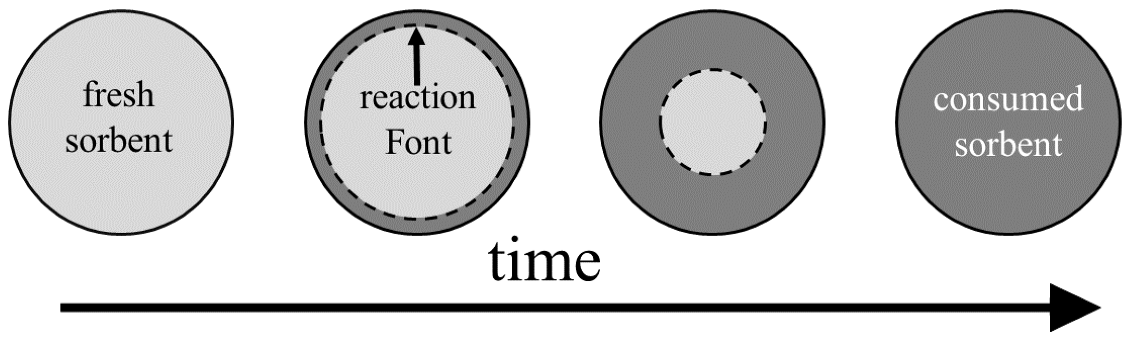
The shrinking core model (SCM), also referred to in the literature as unreacted core model, unlike the deactivation model, is based on a mechanistic view for the sorbent conversion inside the pellets. Initially the fresh sorbent on the pellet surface reacts with H 2 S and forms a layer of solid product (consumed sorbent, colloquially called the ash layer). In the continuation of the process, H 2 S diffuses through the consumed sorbent layer to reach the fresh sorbent. Since the reaction rate is considered to be much faster than the diffusion rate, the reaction takes place on a sharp front separating the consumed sorbent from the fresh sorbent, as seen in Figure 4 as the reaction interface.
The two main transport mechanisms in the SCM are: diffusion through the consumed sorbent layer and surface reaction. The fluxes attributed to each of these phenomena are equal on the reaction interface since there is no accumulation of H 2 S on the interface. Therefore, we can derive an expression for the flux to the pellets that reads as [118]:
N p = 1 k R x + 1 k D f 1 C p , s k R x = k s ( 1 X ) 2 / 3 k D f = D a R p ( 1 X ) 1 / 3 1 ( 1 X ) 1 / 3
where k R x and k D f are the mass transfer coefficients of reaction and diffusion, respectively, k s is the reaction rate function of the surface reaction, R p is the characteristic length of diffusion which in case of spherical pellets corresponds to the pellet radius, D a is the apparent diffusivity of H 2 S in the consumed sorbent and X is the sorbent conversion. Notice that the k R x is derived by assuming that the surface reaction is of first order with respect to the gas. The sorbent conversion is obtained from a mass balance over the sorbent:
X t = γ a p C MO N p I . C . : X ( x , 0 ) = 0
where C MO is the molar concentration of the sorbent (calculated from the density and the molecular weight of the metal oxide) and γ is the stoichiometric coefficient of the sorbent. Equation (17) together with Equations (22) and (23) are solved simultaneously to obtain the solid conversion X ( x , t ) and the H 2 S concentration C ( x , t ) along the bed at different times. Solving the coupled equations can be numerically expensive. To mitigate this problem, a method referred to as constant pattern method was frequently adopted in the literature. Wang et al. [119] presents a simple description of the constant pattern method applied to the SCM.
Table 7 gives the apparent diffusivity for different metal oxides obtained from applying the SCM to fit experimentally measured breakthrough curves. As pointed out in earlier works [120], the estimated diffusivities are relatively large when compared with values obtained from correlations for molecular or Knudsen diffusion (the value of D a for iron oxyhydroxide is much lower compared to those of the other sorbents in Table 7 which is due to the low operating temperature in which the measurements for this sorbent were done). This hints to additional phenomena that accompany the sulfidation process and that are not covered by the SCM, an aspect which needs to be considered when using the SCM for optimizing the pellet properties.
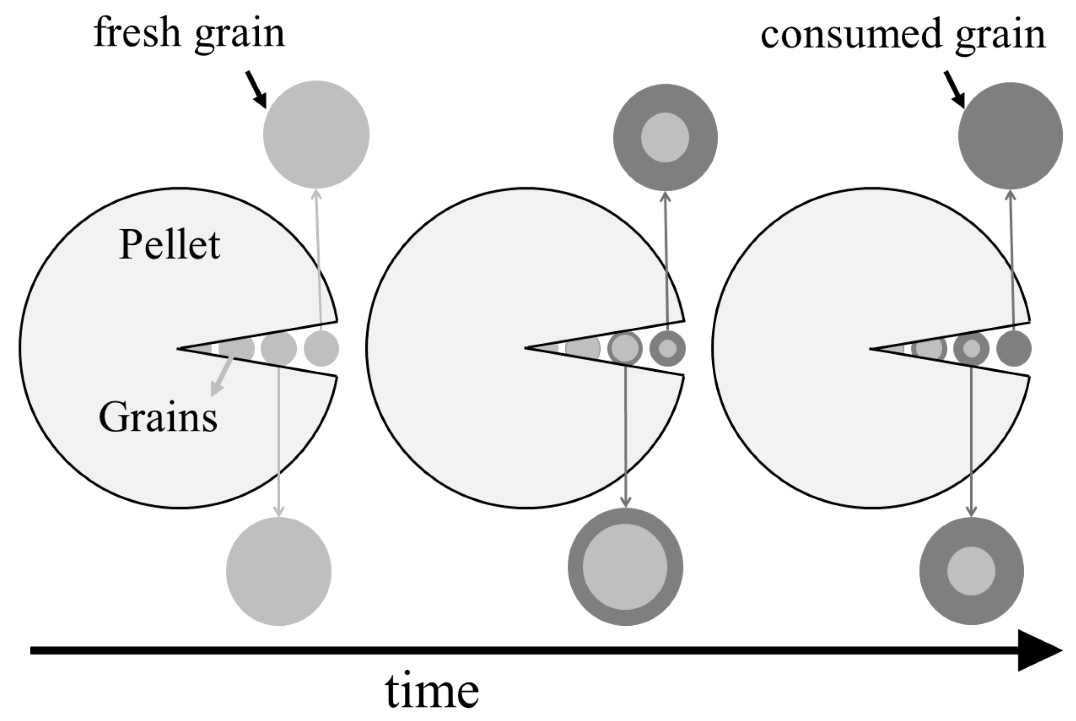
5.3. Grain Model

The grain model considers the pellets to consist of smaller grains, as shown in Figure 5. The void spaces between the grains represent the pores in the pellet and the grains mimic the non-porous part of the pellet. H 2 S diffuses through the pellet pores to reach the grain surfaces. There, the grains follow a shrinking core type of behavior, i.e., H 2 S diffuses through the non-porous consumed sorbent that covers the grain surface (i.e., the ash layer) to reach the fresh sorbent where it reacts, forming a sharp reaction interface that separates the fresh sorbent from the consumed sorbent [118]. The grain model thus adds another scale to the modeling, namely the grain scale on which the ash diffusion and the reaction take place. The main transport phenomenon on the pellet scale is the intra-pellet diffusion, while the convective flow through the packed bed is the main phenomenon on the bed scale. Hence, Equation (17) is still valid to describe the bed scale and only the modeling of the pellet flux N p is refined. The latter is derived from the concentration distribution inside the pellets that is governed by a mass balance over the pellet. For a spherical pellet containing non-porous grains the mass balance of H 2 S reads as:
ε p C p t = 1 r 2 r D e r 2 C p r ( 1 ε p ) a g N g B . C . : C p r = 0 at r = 0 C p = C p , s at r = R p I . C . : C p = 0
where C p is the H 2 S concentration inside the pellet, ε p is the pellet porosity, a g is the specific surface area per unit volume of the grains ( a g = 6 / d g for spherical grains of diameter d g ), D e is the effective intra-pellet diffusivity and N g is the flux of H 2 S to the grains. It is suggested that effective intra-pellet diffusivity follows D e ε p 2 D p to count for the effect of the porous media and tortuosity of the pores [39,127]. Pore diffusivity D p is typically expressed as a combination of the molecular diffusivity D M and the Knudsen diffusivity D K :
D p = 1 D M + 1 D K 1
The values of D M and D K are calculated from the expressions found in the literature [45]. To find the flux to the grains N g we establish a shrinking core model on the grain scale. Following a similar argument that lead to Equation (22) results in:
N g = 1 k R x + 1 k D f 1 C p k R x = k s ( 1 X ) 2 / 3 k D f = D ash R g ( 1 X ) 1 / 3 1 ( 1 X ) 1 / 3
where k s is the surface reaction rate function, D ash is the diffusivity of H 2 S in the consumed sorbent and R g is the characteristic length of grain diffusion which in case of spherical grains corresponds to the grain radius. The sorbent conversion X is obtained similarly as in the SCM (Equation (23)):
X t = γ a g C MO N g I . C . : X = 0 .
Notice that with respect to the SCM where the sorbent conversion is only a function of time and the axial coordinate x brought in by the bed scale, here, the sorbent conversion also depends on the radial position inside the pellet r.
The flux to the pellets that connects pellet the scale to the bed scale reads as:
N p = D e C p r at r = R p .
Combining the grain model governed by Equations (24)–(28) with the packed model governed by Equation (17) leads to a coupled system of equations whose solution is comprised of the concentration field of H 2 S in the fluid bulk, C ( x , t ) , the concentration field of H 2 S in the pellets, C p ( r , x , t ) , and the field of sorbent conversion X ( r , x , t ) . Deriving these three fields by simultaneously solving the governing equations is numerically demanding. Therefore, it is common to make additional assumptions that allow for simplifying the model, for example, by lumping the intra-pellet diffusion into an intra-pellet mass transfer coefficient [128].
Table 8 gives the numerical values of the ash diffusivity obtained by fitting the grain model to experimental data. Compared to the apparent diffusivities obtained from the SCM (Table 7), the ash diffusivities derived from the grain model are several order of magnitude smaller and fall in the range that is expected for diffusion through a non-porous solid matrix. The value of D ash for zinc oxide in Table 8 is much smaller than those of the other sorbents which is due to a slightly modified grain model that was used to analyze the experimental data in this study [64].

5.4. Dimensional Analysis

The modeling approaches presented above not only provide a tool for the prediction of the behavior of a packed bed sorption process, but also, they can be used for the analysis of the process which together with experimental data gives further insights that are of use beyond the scope of process modeling.
In the following we focus on the shrinking core model that describes phenomena taking place on the pellet scale and on the bed scale (see Figure 1). Specifically, the pellet scale is the scene of reaction and intra-pellet diffusion. The characteristic times of these two processes read as τ R x = R p / k s and τ D = R p 2 / D a for reaction and diffusion, respectively. The ratio of these two time-scales defines a Damkohler number:
Da = ( rate   of   reaction ) ( rate   of   diffusion ) = τ D τ R x = k s R p D a
(the Damkohler number defined in Equation (29) can be derived rigorously by multiplying Equation (23) by τ D and substituting for a p = 6 / R p which after some re-arrangement recovers Da.) Typically, pellet sizes are of the order of R p 10 2 m, while the rate function of the surface reaction and the intra-pellet diffusivity are of the order of k s 10 2 m/s (see Table 3) and D a 10 6 m 2 /s, which corresponds to a Damkohler number of Da 10 2 . Such a large Damkohler number implies that diffusion is the rate limiting step on the pellet scale.
The knowledge that diffusion is the rate-limiting step on the pellet scale also guides the analysis of the bed scale, that is the scene of convection. The characteristic time of convection is equal to the residence time τ = L / u i n t . The ratio of the diffusion time scale τ D and the convection time scale τ defines a Peclet number:
Pe = ( rate   of   convection ) ( rate   of   diffusion ) = τ D τ = R p 2 τ D a .
Clearly, effective operation of the packed bed requires Pe 1 to make sure that the gaseous reactant has enough residence time in the bed to fully diffuse through the pellets. Based on this, we can derive a lower limit for the fluid residence time in the packed bed sorber, as:
τ min R p 2 D a .
This approximation can help with sizing the reactor in cases where the flow rate is fixed.

6. Summary

This review paper presents the viable metal oxide candidates to remove H 2 S. Among the studied reactor configurations, packed bed reactors are more favorable as they provide the highest contact-surface area between the solid and gas phase, which is important in cases where deep removal of H 2 S is required. The kinetics and equilibrium of the reaction between metal oxides and H 2 S is reviewed and approximations for obtaining the operating temperature interval for the metal oxides based on kinetic and equilibrium data are derived. The size and structure of pellets can affect the performance of the sorbent. A guideline on finding the optimum pellet size is presented in this work. Simple approximations are derived to estimate sorbent utilization and the quality of sorbent sulfidation. It is suggested to add inert solid to the sorbent to avoid fusion of particles during sulfidation. An approximation to estimate the minimum necessary amount of inert is also derived in this work. The most common modeling methods to describe the solid–gas reaction of H 2 S and metal oxides are discussed and reviewed. Among the reviewed models, the grain model is the most comprehensive in describing the sulfidation process with physically meaningful parameters but it is numerically expensive.
The modeling of sulfur removal processes has received relatively little attention within the last years, especially when compared to works that develop and explore novel sorbent materials. However, the transfer of the lab results obtained with these sorbents to the industrial scale will require a thorough quantitative understanding of the underlying processes. Process models that account for the various phenomena that take place in a packed bed unit can provide such understanding in a rational manner. Development of numerical models that account for the various scales of a packed bed sorption process and routines for parameter estimation are therefore seen as important directions for future work.

Author Contributions

R.S.-V. conceptualized and planed the work. R.S.-V. and M.U.B. executed the research and wrote the paper together

Funding

Financial support from the Swedish Gasification Centre consortium (Phase III), funded by the Swedish Energy Agency and the academic and industrial partners is gratefully acknowledged.

Conflicts of Interest

The authors declare no conflict of interest.

Nomenclature

Across section area packed bed, m 2
alattice constant metal oxide crystal, m
a p specific surface area per unit volume pellet, m 1
a g specific surface area per unit volume grains, m 1
Cconcentration, mol/m 3
C MO molar concentration solid metal oxide, mol/m 3
Ddiffusion coefficient, m 2 /s
d 0 reactor diameter, m
d p pellet size, m
Eaxial dispersion coefficient packed bed, m 2 /s
E a activation energy, J/mol
Gvolume expansion, m 3 /kg
k D f mass transfer coefficient diffusion process, m/s
k g external mass transfer coefficient, m/s
k R x mass transfer coefficient reaction process, m/s
k s kinetic rate function surface reaction, m/s
k s kinetic rate function, m 4 /(mol s)
k α deactivation rate constant, (mol/m 3 ) m
k 0 kinetic prefactor, m/s
Lbed length, m
Mmolecular weight, kg/mol
m s mass of sorbent, kg
Nmolar flux, mol/m 2 /s
Qvolumetric gas flow rate, m 3 /s
Rgas constant, R = 8.315 J/(mol K)
R g grain radius, m
R p pellet radius, m
rreaction rate, mol/(m 2 s)
Sspecific surface area, m 2 /kg
Ttemperature, K
u i n t interstitial velocity, u i n t = Q / ( ε b A ) , m/s
VVolume reactor shell, V = A L , m 3
Xconversion of solid sorbent, –
x i weight fraction metal oxide i, –
Greek symbols
α activation coefficient lumped model, –
γ stoichiometric coefficient, –
ε b bed porosity, –
ε p pellet porosity, –
ζ sorbent utilization, –
η removal efficiency, –
μ viscosity, kg/m/s
ν solidity of the packed bed, ν = ( 1 ε b ) / ε b , –
ρ structural (or true) density, kg/m 3
ρ p apparent pellet density, kg/m 3
ϕ particle volume fraction, ϕ = 1 ε b , –
τ fluid residence time in the packed bed, τ = L / u i n t , s
τ b breakthrough time, s
τ 0 superstitial residence time, τ 0 = V / Q , s

Appendix A

Appendix A.1. Solid Densities

Density of the solid material that is consisted of different compounds with specific mass fractions x i is obtained from:
ρ s = 1 i ( x i / ρ i )
ρ p = ( 1 ε p ) ρ s
ρ b = ( 1 ε b ) ρ p
where ρ i is the structural density of compound i, ρ s is the solid density, ρ p is the pellet density and ρ b is the bed density.

Appendix A.2. Gas Mixture Properties

ρ g , i is the gas density of compound i in the mixture.
The viscosity of gas mixture is estimated from [132]:
μ g = y i μ i M i 0.5 y i M i 0.5
where μ g is the viscosity of the gas mixture, μ i is the viscosity of pure component i in SI units and M i is the molar weight of component i in g/mol. The pure component viscosity μ i is obtained from Chapman–Enskog equation according to:
μ i = 8.44 × 10 25 ( M i T ) 0.5 σ i 2 Ω i
where M i is the molecular weight, T is the absolute temperature, σ i is the hard sphere diameter of the gas molecule and Ω i is the collision integral for species i. A parametrization of the latter is given in [132] as: Ω i = 1.16145 ( k b T / ϵ i ) 0.14874 + 0.52487 × 10 0.77320 k b T / ϵ i + 2.16178 × 10 2.43787 k b T / ϵ i , where k b = 1.38048 × 10 23 J K 1 is the Boltzmann constant and ϵ i is the characteristic Lennard–Jones energy of species i. Please note that all the parameters are in SI units expect for M i in Equation (A2). Values for σ i and ϵ i for several gas species can be found in [132].

References

  1. Roth, S. Hydrogen sulfide. In Handbook of Hazardous Materials; Academic Press: San Diego, CA, USA, 1993; pp. 367–376. [Google Scholar]
  2. Coward, H.; Jones, G. Limits of Flammability of Gases and Vapors; Technical Report; Bureau of Mines: Washington, DC, USA, 1952. [Google Scholar]
  3. Reiffenstein, R.; Hulbert, W.; Roth, S. Toxicology of hydrogen sulfide. Annu. Rev. Pharmacol. Toxicol. 1992, 32, 109–134. [Google Scholar] [CrossRef] [PubMed]
  4. Ewing, S. Electrochemical studies of the hydrogen sulfide corrosion mechanism. Corrosion 1955, 11, 51–55. [Google Scholar] [CrossRef]
  5. Fawcett, H. Hydrogen sulfide—Killer that may not stink. J. Chem. Educ. 1948, 25, 511. [Google Scholar] [CrossRef]
  6. Likens, G.; Wright, R.; Galloway, J.; Butler, T. Acid rain. Sci. Am. 1979, 241, 43–51. [Google Scholar] [CrossRef]
  7. Lew, S.; Jothimurugesan, K.; Flytzani-Stephanopoulos, M. High-temperature hydrogen sulfide removal from fuel gases by regenerable zinc oxide-titanium dioxide sorbents. Ind. Eng. Chem. Res. 1989, 28, 535–541. [Google Scholar] [CrossRef]
  8. Abdoulmoumine, N.; Adhikari, S.; Kulkarni, A.; Chattanathan, S. A review on biomass gasification syngas cleanup. Appl. Energy 2015, 155, 294–307. [Google Scholar] [CrossRef]
  9. Yuan, W.; Bandosz, T. Removal of hydrogen sulfide from biogas on sludge-derived adsorbents. Fuel 2007, 86, 2736–2746. [Google Scholar] [CrossRef]
  10. Gardner, T.; Berry, D.; Lyons, K.; Beer, S.; Freed, A. Fuel processor integrated H2S catalytic partial oxidation technology for sulfur removal in fuel cell power plants. Fuel 2002, 81, 2157–2166. [Google Scholar] [CrossRef]
  11. Sander, R. Compilation of Henry’s law constants (version 4.0) for water as solvent. Atmos. Chem. Phys. 2015, 15, 4399–4981. [Google Scholar] [CrossRef] [Green Version]
  12. Kohl, A.; Nielsen, R. Gas Purification; Elsevier: Amsterdam, The Netherlands, 1997. [Google Scholar]
  13. Awe, O.W.; Zhao, Y.; Nzihou, A.; Minh, D.P.; Lyczko, N. A review of biogas utilisation, purification and upgrading technologies. Waste Biomass Valorization 2017, 8, 267–283. [Google Scholar] [CrossRef] [Green Version]
  14. de Falco, G.; Montagnaro, F.; Balsamo, M.; Erto, A.; Deorsola, F.; Lisi, L.; Cimino, S. Synergic effect of Zn and Cu oxides dispersed on activated carbon during reactive adsorption of H2S at room temperature. Microporous Mesoporous Mater. 2018, 257, 135–146. [Google Scholar] [CrossRef]
  15. Balsamo, M.; Cimino, S.; De Falco, G.; Erto, A.; Lisi, L. ZnO-CuO supported on activated carbon for H2S removal at room temperature. Chem. Eng. J. 2016, 304, 399–407. [Google Scholar] [CrossRef]
  16. Bajaj, B.; Joh, H.I.; Jo, S.M.; Park, J.H.; Yi, K.B.; Lee, S. Enhanced reactive H2S adsorption using carbon nanofibers supported with Cu/CuxO nanoparticles. Appl. Surf. Sci. 2018, 429, 253–257. [Google Scholar] [CrossRef]
  17. Hervy, M.; Minh, D.; Gerente, C.; Weiss-Hortala, E.; Nzihou, A.; Villot, A.; Le Coq, L. H2S removal from syngas using wastes pyrolysis chars. Chem. Eng. J. 2018, 334, 2179–2189. [Google Scholar] [CrossRef] [Green Version]
  18. Sun, Y.; Zhang, J.P.; Wen, C.; Zhang, L. An enhanced approach for biochar preparation using fluidized bed and its application for H2S removal. Chem. Eng. Process. Process Intensif. 2016, 104, 1–12. [Google Scholar] [CrossRef]
  19. Abatzoglou, N.; Boivin, S. A review of biogas purification processes. Biofuels Bioprod. Biorefining 2009, 3, 42–71. [Google Scholar] [CrossRef]
  20. Nowicki, P.; Skibiszewska, P.; Pietrzak, R. Hydrogen sulphide removal on carbonaceous adsorbents prepared from coffee industry waste materials. Chem. Eng. J. 2014, 248, 208–215. [Google Scholar] [CrossRef]
  21. Persson, M.; Jönsson, O.; Wellinger, A. Biogas upgrading to vehicle fuel standards and grid injection. In IEA Bioenergy; Task 37; IEA: Paris, France, 2006; pp. 1–34. [Google Scholar]
  22. Allegue, L.; Hinge, J. Biogas Upgrading Evaluation of Methods for H2S Removal; Danish Technological Institute: Taastrup, Denmark, 2014. [Google Scholar]
  23. Syed, M.; Soreanu, G.; Falletta, P.; Béland, M. Removal of hydrogen sulfide from gas streams using biological processes—A review. Can. Biosyst. Eng. 2006, 48, 2. [Google Scholar]
  24. Khoshnevisan, B.; Tsapekos, P.; Alfaro, N.; Díaz, I.; Fdz-Polanco, M.; Rafiee, S.; Angelidaki, I. A review on prospects and challenges of biological H2S removal from biogas with focus on biotrickling filtration and microaerobic desulfurization. Biofuel Res. J. 2017, 4, 741–750. [Google Scholar] [CrossRef] [Green Version]
  25. Krayzelova, L.; Bartacek, J.; Díaz, I.; Jeison, D.; Volcke, E.; Jenicek, P. Microaeration for hydrogen sulfide removal during anaerobic treatment: A review. Rev. Environ. Sci. Bio/Technol. 2015, 14, 703–725. [Google Scholar] [CrossRef]
  26. Soreanu, G.; Beland, M.; Falletta, P.; Edmonson, K.; Seto, P. Investigation on the use of nitrified wastewater for the steady-state operation of a biotrickling filter for the removal of hydrogen sulphide in biogas. J. Environ. Eng. Sci. 2008, 7, 543–552. [Google Scholar] [CrossRef]
  27. Liu, D.; Wang, Q.; Wu, J.; Liu, Y. A review of sorbents for high-temperature hydrogen sulfide removal from hot coal gas. Environ. Chem. Lett. 2019, 17, 259–276. [Google Scholar] [CrossRef]
  28. Tamhankar, S.; Bagajewicz, M.; Gavalas, G.; Sharma, P.; Flytzani-Stephanopoulos, M. Mixed-oxide sorbents for high-temperature removal of hydrogen sulfide. Ind. Eng. Chem. Process Des. Dev. 1986, 25, 429–437. [Google Scholar] [CrossRef]
  29. Jensen, A.; Webb, C. Treatment of H2S-containing gases: A review of microbiological alternatives. Enzym. Microb. Technol. 1995, 17, 2–10. [Google Scholar] [CrossRef]
  30. Torres, W.; Pansare, S.; Goodwin, J., Jr. Hot gas removal of tars, ammonia, and hydrogen sulfide from biomass gasification gas. Catal. Rev. 2007, 49, 407–456. [Google Scholar] [CrossRef]
  31. Yung, M.; Jablonski, W.; Magrini-Bair, K. Review of catalytic conditioning of biomass-derived syngas. Energy Fuels 2009, 23, 1874–1887. [Google Scholar] [CrossRef]
  32. Woolcock, P.; Brown, R. A review of cleaning technologies for biomass-derived syngas. Biomass Bioenergy 2013, 52, 54–84. [Google Scholar] [CrossRef]
  33. Wiheeb, A.; Shamsudin, I.; Azmier Ahmad, M.; Nazri Murat, M.; Kim, J.; Roslee Othman, M. Present technologies for hydrogen sulfide removal from gaseous mixtures. Rev. Chem. Eng. 2013, 29, 449–470. [Google Scholar] [CrossRef]
  34. Prabhansu; Karmakar, M.; Chandra, P.; Chatterjee, P. A review on the fuel gas cleaning technologies in gasification process. J. Environ. Chem. Eng. 2015, 3, 689–702. [Google Scholar] [CrossRef]
  35. Singhal, S.; Agarwal, S.; Arora, S.; Sharma, P.; Singhal, N. Upgrading techniques for transformation of biogas to bio-CNG: A review. Int. J. Energy Res. 2017, 41, 1657–1669. [Google Scholar] [CrossRef]
  36. Cheah, S.; Carpenter, D.; Magrini-Bair, K. Review of mid-to high-temperature sulfur sorbents for desulfurization of biomass-and coal-derived syngas. Energy Fuels 2009, 23, 5291–5307. [Google Scholar] [CrossRef]
  37. Dolan, M.; Ilyushechkin, A.; McLennan, K.; Sharma, S. Sulfur removal from coal-derived syngas: Thermodynamic considerations and review. Asia-Pac. J. Chem. Eng. 2012, 7, 1–13. [Google Scholar] [CrossRef]
  38. Woods, M.; Gangwal, S.; Jothimurugesan, K.; Harrison, D. Reaction between hydrogen sulfide and zinc oxide-titanium oxide sorbents. 1. Single-pellet kinetic studies. Ind. Eng. Chem. Res. 1990, 29, 1160–1167. [Google Scholar] [CrossRef]
  39. Jothimurugesan, K.; Harrison, D. Reaction between hydrogen sulfide and zinc oxide-titanium oxide sorbents. 2. Single-pellet sulfidation modeling. Ind. Eng. Chem. Res. 1990, 29, 1167–1172. [Google Scholar] [CrossRef]
  40. Adanez, J.; Garcia-Labiano, F.; De Diego, L.; Fierro, V. H2S removal in entrained flow reactors by injection of Ca-based sorbents at high temperatures. Energy Fuels 1998, 12, 726–733. [Google Scholar] [CrossRef]
  41. Mojtahedi, W.; Abbasian, J. H2S removal from coal gas at elevated temperature and pressure in fluidized bed with zinc titanate sorbents. 1. Cyclic tests. Energy Fuels 1995, 9, 429–434. [Google Scholar] [CrossRef]
  42. McCabe, W.; Smith, J.; Harriott, P. Unit Operations of Chemical Engineering; McGraw-Hill: New York, NY, USA, 1993. [Google Scholar]
  43. Benyahia, F.; O’Neill, K. Enhanced voidage correlations for packed beds of various particle shapes and sizes. Part. Sci. Technol. 2005, 23, 169–177. [Google Scholar] [CrossRef]
  44. Fogler, H. Elements of Chemical Reaction Engineering; Prentice Hall: Upper Saddle River, NJ, USA, 2016. [Google Scholar]
  45. Perry, R.; Green, D. Perry’s Chemical Engineers’ Handbook; McGraw-Hill Professional: New York, NY, USA, 1999. [Google Scholar]
  46. Cussler, E. Diffusion: Mass Transfer in Fluid Systems; Cambridge University Press: Cambridge, UK, 2009. [Google Scholar]
  47. Woods, M.; Gangwal, S.; Harrison, D.; Jothimurugesan, K. Kinetics of the reactions of a zinc ferrite sorbent in high-temperature coal gas desulfurization. Ind. Eng. Chem. Res. 1991, 30, 100–107. [Google Scholar] [CrossRef]
  48. Chauk, S.; Agnihotri, R.; Jadhav, R.; Misro, S.; Fan, L.S. Kinetics of high-pressure removal of hydrogen sulfide using calcium oxide powder. AIChE J. 2000, 46, 1157–1167. [Google Scholar] [CrossRef]
  49. Westmoreland, P.; Harrison, D. Evaluation of candidate solids for high-temperature desulfurization of low-Btu gases. Environ. Sci. Technol. 1976, 10, 659–661. [Google Scholar] [CrossRef]
  50. Westmoreland, P.; Gibson, J.; Harrison, D. Comparative kinetics of high-temperature reaction between hydrogen sulfide and selected metal oxides. Environ. Sci. Technol. 1977, 11, 488–491. [Google Scholar] [CrossRef]
  51. García, E.; Cilleruelo, C.; Ibarra, J.; Pineda, M.; Palacios, J. Kinetic study of high-temperature removal of H2S by novel metal oxide sorbents. Ind. Eng. Chem. Res. 1997, 36, 846–853. [Google Scholar] [CrossRef]
  52. Ko, T.H.; Chu, H.; Chaung, L.K. The sorption of hydrogen sulfide from hot syngas by metal oxides over supports. Chemosphere 2005, 58, 467–474. [Google Scholar] [CrossRef] [PubMed]
  53. Polychronopoulou, K.; Cabello Galisteo, F.; López Granados, M.; Fierro, J.; Bakas, T.; Efstathiou, A. Novel Fe–Mn–Zn–Ti–O mixed-metal oxides for the low-temperature removal of H2S from gas streams in the presence of H2, CO2, and H2O. J. Catal. 2005, 236, 205–220. [Google Scholar] [CrossRef]
  54. Polychronopoulou, K.; Fierro, J.; Efstathiou, A. Novel Zn–Ti-based mixed metal oxides for low-temperature adsorption of H2S from industrial gas streams. Appl. Catal. B 2005, 57, 125–137. [Google Scholar] [CrossRef]
  55. Jiang, D.; Su, L.; Ma, L.; Yao, N.; Xu, X.; Tang, H.; Li, X. Cu–Zn–Al mixed metal oxides derived from hydroxycarbonate precursors for H2S removal at low temperature. Appl. Surf. Sci. 2010, 256, 3216–3223. [Google Scholar] [CrossRef]
  56. Liu, G.; Huang, Z.H.; Kang, F. Preparation of ZnO/SiO2 gel composites and their performance of H2S removal at room temperature. J. Hazard. Mater. 2012, 215, 166–172. [Google Scholar] [CrossRef]
  57. Harrison, D. Performance analysis of ZnO-based sorbents in removal of H2S from fuel gas. In Desulfurization of Hot Coal Gas; Springer: Berlin/Heidelberg, Germany, 1998; pp. 213–242. [Google Scholar]
  58. Rajagopalan, V.; Amiridis, M. Hot coal gas desulfurization by perovskite-type sorbents. Ind. Eng. Chem. Res. 1999, 38, 3886–3891. [Google Scholar] [CrossRef]
  59. Cheah, S.; Olstad, J.; Jablonski, W.; Magrini-Bair, K.A. Regenerable manganese-based sorbent for cleanup of simulated biomass-derived syngas. Energy Fuels 2011, 25, 379–387. [Google Scholar] [CrossRef]
  60. Zhang, R.; Wang, B.; Wei, L. Sulfidation growth and characterization of nanocrystalline ZnS thin films. Vacuum 2008, 82, 1208–1211. [Google Scholar] [CrossRef]
  61. Meng, X.; De Jong, W.; Pal, R.; Verkooijen, A. In bed and downstream hot gas desulphurization during solid fuel gasification: A review. Fuel Process. Technol. 2010, 91, 964–981. [Google Scholar] [CrossRef]
  62. Meng, X.; De Jong, W.; Verkooijen, A. Thermodynamic analysis and kinetics model of H2S sorption using different sorbents. Environ. Prog. Sustain. Energy 2009, 28, 360–371. [Google Scholar] [CrossRef]
  63. Osman, A.; Abu-Dahrieh, J.; McLaren, M.; Laffir, F.; Nockemann, P.; Rooney, D. A facile green synthetic route for the preparation of highly active γ-Al2O3 from aluminum foil waste. Sci. Rep. 2017, 7, 3593. [Google Scholar] [CrossRef] [PubMed] [Green Version]
  64. Babé, C.; Tayakout-Fayolle, M.; Geantet, C.; Vrinat, M.; Bergeret, G.; Huard, T.; Bazer-Bachi, D. Crystallite size effect in the sulfidation of ZnO by H2S: Geometric and kinetic modelling of the transformation. Chem. Eng. Sci. 2012, 82, 73–83. [Google Scholar] [CrossRef]
  65. Rumble, J. Handbook of Chemistry and Physics, Internet Version; CRC Press: Boca Raton, FL, USA, 2019. [Google Scholar]
  66. Yoon, Y.I.; Kim, M.W.; Yoon, Y.S.; Kim, S.H. A kinetic study on medium temperature desulfurization using a natural manganese ore. Chem. Eng. Sci. 2003, 58, 2079–2087. [Google Scholar] [CrossRef]
  67. Tamhankar, S.; Hasatani, M.; Wen, C. Kinetic studies on the reactions involved in the hot gas desulfurization using a regenerable iron oxide sorbent I: Reduction and sulfidation of iron oxide. Chem. Eng. Sci. 1981, 36, 1181–1191. [Google Scholar] [CrossRef]
  68. Pan, Y.; Perales, J.; Velo, E.; Puigjaner, L. Kinetic behaviour of iron oxide sorbent in hot gas desulfurization. Fuel 2005, 84, 1105–1109. [Google Scholar] [CrossRef]
  69. Zeng, B.; Li, H.; Huang, T.; Liu, C.; Yue, H.; Liang, B. Kinetic study on the sulfidation and regeneration of manganese-based regenerable sorbent for high temperature H2S removal. Ind. Eng. Chem. Res. 2015, 54, 1179–1188. [Google Scholar] [CrossRef]
  70. Lew, S.; Sarofim, A.; Flytzani-Stephanopoulos, M. Sulfidation of zinc titanate and zinc oxide solids. Ind. Eng. Chem. Res. 1992, 31, 1890–1899. [Google Scholar] [CrossRef]
  71. Fenouil, L.; Lynn, S. Study of calcium-based sorbents for high-temperature H2S removal. 1. Kinetics of H2S sorption by uncalcined limestone. Ind. Eng. Chem. Res. 1995, 34, 2324–2333. [Google Scholar] [CrossRef]
  72. Li, Z.; Flytzani-Stephanopoulos, M. Cu-Cr-O and Cu-Ce-O regenerable oxide sorbents for hot gas desulfurization. Ind. Eng. Chem. Res. 1997, 36, 187–196. [Google Scholar] [CrossRef]
  73. Kobayashi, M.; Flytzani-Stephanopoulos, M. Reduction and sulfidation kinetics of cerium oxide and Cu-modified cerium oxide. Ind. Eng. Chem. Res. 2002, 41, 3115–3123. [Google Scholar] [CrossRef]
  74. Couper, J. Process Engineering Economics; CRC Press: Boca Raton, FL, USA, 2003. [Google Scholar]
  75. Jia, L.; Hughes, R.; Lu, D.; Anthony, E.; Lau, I. Attrition of calcining limestones in circulating fluidized-bed systems. Ind. Eng. Chem. Res. 2007, 46, 5199–5209. [Google Scholar] [CrossRef]
  76. Tiemann, M. Porous metal oxides as gas sensors. Chemistry 2007, 13, 8376–8388. [Google Scholar] [CrossRef] [PubMed]
  77. Sasaoka, E.; Hirano, S.; Kasaoka, S.; Sakata, Y. Characterization of reaction between zinc oxide and hydrogen sulfide. Energy Fuels 1994, 8, 1100–1105. [Google Scholar] [CrossRef]
  78. Sasaoka, E.; Sakamoto, M.; Ichio, T.; Kasaoka, S.; Sakata, Y. Reactivity and durability of iron oxide high temperature desulfurization sorbents. Energy Fuels 1993, 7, 632–638. [Google Scholar] [CrossRef]
  79. Wang, J.; Guo, J.; Parnas, R.; Liang, B. Calcium-based regenerable sorbents for high temperature H2S removal. Fuel 2015, 154, 17–23. [Google Scholar] [CrossRef]
  80. Akiti, T.; Constant, K.; Doraiswamy, L.; Wheelock, T. A regenerable calcium-based core-in-shell sorbent for desulfurizing hot coal gas. Ind. Eng. Chem. Res. 2002, 41, 587–597. [Google Scholar] [CrossRef] [Green Version]
  81. Jagtap, S.; Wheelock, T. Regeneration of sulfided calcium-based sorbents by a cyclic process. Energy Fuels 1996, 10, 821–827. [Google Scholar] [CrossRef] [Green Version]
  82. Gibson III, J.; Harrison, D. The reaction between hydrogen sulfide and spherical pellets of zinc oxide. Ind. Eng. Chem. Process Des. Dev. 1980, 19, 231–237. [Google Scholar] [CrossRef]
  83. Zhang, J.; Wang, Y.; Wu, D. Effect investigation of ZnO additive on Mn–Fe/γ-Al2O3 sorbents for hot gas desulfurization. Energy Convers. Manag. 2003, 44, 357–367. [Google Scholar] [CrossRef]
  84. Jun, H.K.; Lee, T.J.; Ryu, S.O.; Kim, J.C. A study of Zn-Ti-based H2S removal sorbents promoted with cobalt oxides. Ind. Eng. Chem. Res. 2001, 40, 3547–3556. [Google Scholar] [CrossRef]
  85. Bu, X.; Ying, Y.; Zhang, C.; Peng, W. Research improvement in Zn-based sorbent for hot gas desulfurization. Powder Technol. 2008, 180, 253–258. [Google Scholar] [CrossRef]
  86. Vamvuka, D.; Arvanitidis, C.; Zachariadis, D. Flue gas desulfurization at high temperatures: A review. Environ. Eng. Sci. 2004, 21, 525–548. [Google Scholar] [CrossRef]
  87. Shangguan, J.; Zhao, Y.; Fan, H.; Liang, L.; Shen, F.; Miao, M. Desulfurization behavior of zinc oxide based sorbent modified by the combination of Al2O3 and K2CO3. Fuel 2013, 108, 80–84. [Google Scholar] [CrossRef]
  88. Siriwardane, R.; Woodruff, S. FTIR characterization of the interaction of oxygen with zinc sulfide. Ind. Eng. Chem. Res. 1995, 34, 699–702. [Google Scholar] [CrossRef]
  89. Siriwardane, R.; Woodruff, S. In situ Fourier transform infrared characterization of sulfur species resulting from the reaction of water vapor and oxygen with zinc sulfide. Ind. Eng. Chem. Res. 1997, 36, 5277–5281. [Google Scholar] [CrossRef]
  90. Elseviers, W.; Verelst, H. Transition metal oxides for hot gas desulphurisation. Fuel 1999, 78, 601–612. [Google Scholar] [CrossRef]
  91. Dou, B.; Wang, C.; Chen, H.; Song, Y.; Xie, B.; Xu, Y.; Tan, C. Research progress of hot gas filtration, desulphurization and HCl removal in coal-derived fuel gas: A review. Chem. Eng. Res. Des. 2012, 90, 1901–1917. [Google Scholar] [CrossRef]
  92. Abbasian, J.; Slimane, R. A regenerable copper-based sorbent for H2S removal from coal gases. Ind. Eng. Chem. Res. 1998, 37, 2775–2782. [Google Scholar] [CrossRef]
  93. Slimane, R.; Abbasian, J. Copper-based sorbents for coal gas desulfurization at moderate temperatures. Ind. Eng. Chem. Res. 2000, 39, 1338–1344. [Google Scholar] [CrossRef]
  94. Garcia, E.; Palacios, J.; Alonso, L.; Moliner, R. Performance of Mn and Cu mixed oxides as regenerable sorbents for hot coal gas desulfurization. Energy Fuels 2000, 14, 1296–1303. [Google Scholar] [CrossRef]
  95. Alonso, L.; Palacios, J.; Garcıa, E.; Moliner, R. Characterization of Mn and Cu oxides as regenerable sorbents for hot coal gas desulfurization. Fuel Process. Technol. 2000, 62, 31–44. [Google Scholar] [CrossRef]
  96. Karayilan, D.; Dogu, T.; Yasyerli, S.; Dogu, G. Mn-Cu and Mn-Cu-V mixed-oxide regenerable sorbents for hot gas desulfurization. Ind. Eng. Chem. Res. 2005, 44, 5221–5226. [Google Scholar] [CrossRef]
  97. Yasyerli, S.; Dogu, G.; Ar, I.; Dogu, T. Dynamic analysis of removal and selective oxidation of H2S to elemental sulfur over Cu–V and Cu–V–Mo mixed oxides in a fixed bed reactor. Chem. Eng. Sci. 2004, 59, 4001–4009. [Google Scholar] [CrossRef]
  98. Yasyerli, S.; Dogu, G.; Ar, I.; Dogu, T. Activities of copper oxide and Cu-V and Cu-Mo mixed oxides for H2S removal in the presence and absence of hydrogen and predictions of a deactivation model. Ind. Eng. Chem. Res. 2001, 40, 5206–5214. [Google Scholar] [CrossRef]
  99. Yasyerli, S.; Dogu, G.; Ar, I.; Dogu, T. Breakthrough analysis of H2S removal on Cu-V-Mo, Cu-V, and Cu-Mo mixed oxides. Chem. Eng. Commun. 2003, 190, 1055–1072. [Google Scholar] [CrossRef]
  100. Liu, D.; Zhou, W.; Wu, J. CuO-CeO2/ZSM-5 composites for reactive adsorption of hydrogen sulphide at high temperature. Can. J. Chem. Eng. 2016, 94, 2276–2281. [Google Scholar] [CrossRef]
  101. Buelna, G.; Lin, Y. Characteristics and desulfurization-regeneration properties of sol–gel-derived copper oxide on alumina sorbents. Sep. Purif. Technol. 2004, 39, 167–179. [Google Scholar] [CrossRef]
  102. Karvan, O.; Atakül, H. Investigation of CuO/mesoporous SBA-15 sorbents for hot gas desulfurization. Fuel Process. Technol. 2008, 89, 908–915. [Google Scholar] [CrossRef]
  103. Baeza, P.; Aguila, G.; Gracia, F.; Araya, P. Desulfurization by adsorption with copper supported on zirconia. Catal. Commun. 2008, 9, 751–755. [Google Scholar] [CrossRef]
  104. Alonso, L.; Palacios, J. Performance and recovering of a Zn-doped manganese oxide as a regenerable sorbent for hot coal gas desulfurization. Energy Fuels 2002, 16, 1550–1556. [Google Scholar] [CrossRef]
  105. Alonso, L.; Palacios, J. A TEM and XRD study of the structural changes involved in manganese-based regenerable sorbents for hot coal gas desulfurization. Chem. Mater. 2002, 14, 225–231. [Google Scholar] [CrossRef]
  106. Zhang, J.; Wang, Y.; Ma, R.; Wu, D. A study on regeneration of Mn–Fe–Zn–O supported upon γ-Al2O3 sorbents for hot gas desulfurization. Fuel Process. Technol. 2003, 84, 217–227. [Google Scholar] [CrossRef]
  107. Bakker, W.; Kapteijn, F.; Moulijn, J. A high capacity manganese-based sorbent for regenerative high temperature desulfurization with direct sulfur production: Conceptual process application to coal gas cleaning. Chem. Eng. J. 2003, 96, 223–235. [Google Scholar] [CrossRef]
  108. Wang, J.; Liang, B.; Parnas, R. Manganese-based regenerable sorbents for high temperature H2S removal. Fuel 2013, 107, 539–546. [Google Scholar] [CrossRef]
  109. Li, H.; Su, S.; Hu, S.; Xu, K.; Jiang, L.; Wang, Y.; Xu, J.; Xiang, J. Effect of preparation conditions on MnxOy/Al2O3 sorbent for H2S removal from high-temperature synthesis gas. Fuel 2018, 223, 115–124. [Google Scholar] [CrossRef]
  110. Swisher, J.; Schwerdtfeger, K. Review of metals and binary oxides as sorbents for removing sulfur from coal-derived gases. J. Mater. Eng. Perform. 1992, 1, 399–407. [Google Scholar] [CrossRef]
  111. Fan, H.L.; Li, C.H.; Li, C.H. Testing of iron oxide sorbent for high-temperature coal gas desulfurization. Energy Sources 2005, 27, 245–250. [Google Scholar] [CrossRef]
  112. Bu, X.; Ying, Y.; Ji, X.; Zhang, C.; Peng, W. New development of zinc-based sorbents for hot gas desulfurization. Fuel Process. Technol. 2007, 88, 143–147. [Google Scholar] [CrossRef]
  113. Pishahang, M.; Larring, Y.; van Dijk, E.; van Berkel, F.; Dahl, P.; Cobden, P.; McCann, M.; Bakken, E. Regenerative copper–alumina H2S sorbent for hot gas cleaning through chemical swing adsorption. Ind. Eng. Chem. Res. 2016, 55, 1024–1032. [Google Scholar] [CrossRef]
  114. Ben-Slimane, R.; Hepworth, M. Desulfurization of hot coal-derived fuel gases with manganese-based regenerable sorbents. 2. Regeneration and multicycle tests. Energy Fuels 1994, 8, 1184–1191. [Google Scholar] [CrossRef]
  115. Kunii, D.; Levenspiel, O. Fluidization Engineering; Elsevier: Amsterdam, The Netherlands, 2013. [Google Scholar]
  116. Guo, L.F.; Pan, K.L.; Lee, H.M.; Chang, M.B. High-Temperature Gaseous H2S Removal by Zn–Mn-based Sorbent. Ind. Eng. Chem. Res. 2015, 54, 11040–11047. [Google Scholar] [CrossRef]
  117. Hong, Y.; Zhang, Z.; Cai, Z.; Zhao, X.; Liu, B. Deactivation kinetics model of H2S removal over mesoporous LaFeO3/MCM-41 sorbent during hot coal gas desulfurization. Energy Fuels 2014, 28, 6012–6018. [Google Scholar] [CrossRef]
  118. Szekely, J. Gas-Solid Reactions; Elsevier: Amsterdam, The Netherlands, 2012. [Google Scholar]
  119. Wang, J.; Groves, F.; Harrison, D. Modeling high temperature desulfurization in a fixed-bed reactor. Chem. Eng. Sci. 1990, 45, 1693–1701. [Google Scholar] [CrossRef]
  120. Focht, G.; Ranade, P.; Harrison, D. High-temperature desulfurization using zinc ferrite: Reduction and sulfidation kinetics. Chem. Eng. Sci. 1988, 43, 3005–3013. [Google Scholar] [CrossRef]
  121. Karlegärd, Å.; Bjerle, I. Kinetic studies on high temperature desulphurization of synthesis gas with zinc ferrite. Chem. Eng. Technol. 1994, 17, 21–29. [Google Scholar] [CrossRef]
  122. Fan, Y.; Rajagopalan, V.; Suares, G.; Amiridis, M. Use of an ”unreacted shrinking core” model in the reaction of H2S with perovskite-type sorbents. Ind. Eng. Chem. Res. 2001, 40, 4767–4770. [Google Scholar] [CrossRef]
  123. Rosso, I.; Galletti, C.; Bizzi, M.; Saracco, G.; Specchia, V. Zinc oxide sorbents for the removal of hydrogen sulfide from syngas. Ind. Eng. Chem. Res. 2003, 42, 1688–1697. [Google Scholar] [CrossRef]
  124. Fenouil, L.A.; Lynn, S. Study of calcium-based sorbents for high-temperature H2S removal. 2. Kinetics of H2S sorption by calcined limestone. Ind. Eng. Chem. Res. 1995, 34, 2334–2342. [Google Scholar] [CrossRef]
  125. Ben-Slimane, R.; Hepworth, M. Desulfurization of hot coal-derived fuel gases with manganese-based regenerable sorbents. 1. Loading (sulfidation) tests. Energy Fuels 1994, 8, 1175–1183. [Google Scholar] [CrossRef]
  126. Yamamoto, T.; Tayakout-Fayolle, M.; Geantet, C. Gas-phase removal of hydrogen sulfide using iron oxyhydroxide at low temperature: Measurement of breakthrough curve and modeling of sulfidation mechanism. Chem. Eng. J. 2015, 262, 702–709. [Google Scholar] [CrossRef]
  127. Wakao, N.; Smith, J. Diffiusion in catalyst pellets. Chem. Eng. Sci. 1962, 17, 825–834. [Google Scholar] [CrossRef]
  128. Sadegh-Vaziri, R.; Babler, M. Numerical investigation of the outward growth of ZnS in the removal of H2S in a packed bed of ZnO. Chem. Eng. Sci. 2017, 158, 328–339. [Google Scholar] [CrossRef]
  129. Sotirchos, S.; Zarkanitis, S. Pellet-model effects on simulation models for fixed-bed desulfurization reactors. AIChE J. 1989, 35, 1137–1147. [Google Scholar] [CrossRef]
  130. Efthimiadis, E.; Sotirchos, S. Experimental validation of a mathematical model for fixed-bed desulfurization. AIChE J. 1993, 39, 99–110. [Google Scholar] [CrossRef]
  131. Pineda, M.; Palacios, J.; García, E.; Cilleruelo, C.; Ibarra, J. Modelling of performance of zinc ferrites as high-temperature desulfurizing sorbents in a fixed-bed reactor. Fuel 1997, 76, 567–573. [Google Scholar] [CrossRef]
  132. Reid, R.; Prausnitz, J.; Poling, B. The Properties of Gases and Liquids; McGraw Hill: New York, NY, USA, 1987. [Google Scholar]
Figure 1. Schematic of a packed bed reactor for H 2 S removal with metal oxides: (a) reactor scale, (b) pellet scale.
Applsci 09 05316 g001
Figure 2. Schematic of pellet fusion. (a) The bed is fully packed with metal oxides with a low bed porosity which results in particle fusion during sulfidation. (b) Inert particles are added to the packing to prevent fusion during sulfidation.
Applsci 09 05316 g002
Figure 3. Analysis of breakthrough curves. (a) Schematic of a breakthrough curve indicating the breakthrough time τ b , the surface utilization time τ 1 and the time for complete sorbent utilization τ 2 . (b) Schematic illustration of the sorbent utilization at t = 0 , τ 1 and τ 2 .
Applsci 09 05316 g003
Figure 4. Schematic of the shrinking core model. The light gray is the fresh sorbent and the dark gray is the consumed sorbent. A sharp interface separates the fresh and consumed sorbent. As the conversion proceeds the consumed sorbent shell grows inward.
Applsci 09 05316 g004
Figure 5. Schematic of the grain model. On the grain scale, the light gray is the fresh sorbent and the dark gray is the consumed sorbent. Grains undergo a shrinking core-like of behavior. Grains closer to the pellet surface are consumed sooner as the conversion proceeds in a pellet.
Applsci 09 05316 g005
Table 1. Parameter values of Equation (3) for different pellet shapes [43].
Shape of PelletsABC
Spheres1.7400.3901.140
Cylinders a1.7030.3730.611
a Aspect ratio height/diameter = 0.76 to 1.78 .
Table 2. Gibbs free energy change for the sulfidation of different metal oxides.
Desulfurization Reaction Δ G (kJ/mol)
ZnO + H 2 S ⇌ ZnS + H 2 O 61.3
MnO + H 2 S ⇌ MnS + H 2 O 32.9
CuO + H 2 S ⇌ CuS + H 2 O 110.6
CaO + H 2 S ⇌ CaS + H 2 O 64.6
FeO + H 2 S ⇌ FeS + H 2 O 43.9
Table 3. Kinetic parameter for different metal oxides.
MOTemperature RangePrefactor k 0 Activation Energy E a MethodRef.
Iron-based:
Fe 2 O 3 600–900 C 2.5 × 10 3 cm/s13.8 kJ/molGrain model[67]
Fe 2 O 3 500–800 C-14.7 kJ/mol(not specified)[68]
Manganese-based:
MnO300–800 C0.456 cm/s23.8 kJ/molInitial kinetics[50]
Mn-ore400–600 C0.93 cm/s30.6 kJ/mollInitial kinetics[66]
MnO800–920 C4.16 cm/s37.42 kJ/molShrinking core model[69]
Zinc-based:
ZnO300–750 C0.110 cm/s30.3 kJ/molInitial kinetics[50]
ZnO400–800 C1.31 cm/s43.11 kJ/molInitial kinetics[70]
ZnO550–650 C 3.7 × 10 3 cm/s16.2 kJ/molGrain model[51]
Calcium-based:
CaO300–800 C0.038 cm/s21.6 kJ/molInitial kinetics[50]
CaO650–900 C640 m/s155 kJ/molGrain model[48]
CaCO 3 560–670 C5200 m/s163 kJ/molGrain model[71]
Copper-based: a
CuCeO x 350–750 C-16 kJ/molInitial kinetics[73]
Cu-Cr 2 O 3 650–850 C-19.8 kJ/molInitial kinetics[72]
a Sorbent showed reaction order smaller than one.
Table 4. Durability issues of different metal oxides and possible remediations.
MODurability AssessmentRemediation
CaONot fully regenerable due to formation of calcium sulfate [79]. 50% capacity loss after 3 cycles due to sintering [80]. Slow kinetics at low temperatures, most effective at 880 C [71]. Deep desulfurization is not possible due to thermodynamic constraints [36]. Prone to attrition [80].Regeneration is done by one step oxidation with O 2 followed by reduction with CO [80] or H 2 [81]. Core-shell pelletization leads to 10 cycles of constant removal capacity [80]
ZnOReducing of ZnO in reducing conditions (e.g., in syngas) followed by vaporization of elemental Zn at temperature higher than 600 C leads to sorbent loss and reduction of removal capacity [82,83]. Sulfate formation during regeneration is an issue [57].Doping with Co [84], Mn [85] and Cu [28,86] to increase stability and performance. Addition of Al 2 O 3 [87] or supporting on TiO 2 can improve the stability [61]. Steam regeneration prevents the sulfate formation to a good extend [88,89].
Fe 2 O 3 Reducing environment leads to spongy iron formation that reacts very slowly with H 2 S [67] and instead reacts very fast with a carbon source (e.g., CO or CO 2 ) to form iron carbide [61] or catalyzes the Boudouard reaction and leads to choke formation [90].Using SiO 2 , TiO 2 , and Al 2 O 3 as binders improve the durability [78].
CuO(a) Copper oxides reduce to elemental copper in a reducing environment like syngas and at high temperatures. Elemental copper is one order of magnitude less active than copper oxides in desulfurization [27]. During sulfidation of copper oxide, sintering of the dens sulfide layer at the outer surface of sorbent particles reduces the sorbent utilization [91]. It has a favorable equilibrium therefore deep desulfurization is achievable.Doping with chromium oxide [92] and manganese [93,94,95,96]. Also addition of molybdenum [97], vanadium [96,97,98,99] and cerium [100] can improve the sorbent performance. Dispersion on a support such as γ -Al 2 O 3 [101], SiO 2 [102], and ZrO 2 [103].
MnODoes not have a favorable thermodynamics. Stable even at high temperatures. Prone to form manganese sulfate which is difficult to regenerate.Doping other metal ions into manganese oxide such as Zn [104,105,106], Fe [106] and Al [107,108,109]. Desulfurization at temperatures higher than 700 reduces the chances of sulfate formation [96].
Table 5. Regeneration of spent metal oxides.
SorbentRegeneration AgentOperating ConditionRef.
Ca-basedOxidation with O 2 followed by reduction with CO1050 C, tested for 10 cycles [80]
Fe-basedMixture of 15% steam, 5% O 2 and 80% N 2 400–700 C, tested for 5 cycles [111]
Zn-basedMixture of 50% steam, 3–6% O 2 and balance N 2 650–750 C, tested for 20 cycles [112]
Cu-basedOxidation in air followed by regeneration in a mixture of steam and H 2 375 C, tested for 50 cycles [113]
Mn-basedSO 2 , O 2 , steam or a combination of them. > 600 C, tested for 110 cycles [107]
Air > 900 C, tested for 5 cycles [114]
Table 6. Deactivation model in the literature.
Sorbent n m k s (m/s) k α (s 1 ) Ref.
Cu, M and V oxides01∼10 2 ∼10 2 [99]
Zn-Mn oxides01∼10 2 ∼10 2 [116]
Table 7. Apparent diffusivity in the shrinking core model for different sorbents at given temperature range.
SorbentT ( C) D a (m/s 2 )Ref.
Zinc titanate550–700∼10 7 [119]
Zinc ferrite500–600∼10 5 [119,121]
Perovskite-type sorbents300–500∼10 7 [122]
Zinc oxide250∼10 8 [123]
Calcium oxide560–1100∼10 6 [124]
Manganese based850∼10 6 [125]
Iron oxyhydroxide0–10010 9 [126]
Table 8. Grain model in the literature.
SorbentT ( C) D ash (m/s 2 )Ref.
Mixed oxides500–600∼10 12 [129,130]
Zinc ferrite540–600∼10 12 [131]
Zinc oxide40010 17 [64]

