Article

Numerical Study of a Proposed Semi-Submersible Floating Platform with Different Numbers of Offset Columns Based on the DeepCwind Prototype for Improving the Wave-Resistance Ability

1
School of Civil Engineering and Mechanics, Huazhong University of Science and Technology, Wuhan 430074, China
2
Department of Architecture and Building Engineering, Tokyo Institute of Technology, Yokohama, Kanagawa 1528550, Japan
3
Department of Civil Engineering, School of Engineering, The University of Tokyo, 7-3-1 Hongo, Bunkyo-ku, Tokyo 1138656, Japan
*
Author to whom correspondence should be addressed.
Submission received: 29 January 2019 / Revised: 18 March 2019 / Accepted: 20 March 2019 / Published: 25 March 2019
(This article belongs to the Special Issue Offshore Wind Energy)

Abstract

:
DeepCwind semi-submersible floating offshore wind turbines have been widely examined, and in some countries this type of floating offshore wind turbine has been adopted in the construction of floating wind farms. However, the DeepCwind semi-submersible floating offshore wind turbines still experience large surge motion that limits their operational time. Therefore, in this study, a semi-submersible floating platform with different numbers of offset columns, but with the same total weight, based on the DeepCwind prototype is proposed. From the free-decay test, it was found that the number of the floating columns will affect the natural frequency of the platform. Furthermore, the regular wave test in the time domain and the irregular wave test in the frequency domain show that increasing the number of the floating columns will reduce the surge motion greatly, while the effects in the heave and pitch motions are not obvious.

1. Introduction

As traditional energy sources have been increasingly exhausted over the past decades, renewable energy, especially wind energy, has received more attention than ever before. Wind energy has less environmental pollution and can reduce greenhouse gas emissions such as carbon dioxide. Because wind energy has such good properties and meets the expectations of improving the global climate, it has been promoted and developed over the past few decades, and the technology is becoming more mature. According to relevant reports, the annual share of wind energy used to generate electricity in the world is increasing, and has reached 2.74 × 10⁹ MW [1]. On the other hand, in wind energy production, due to factors such as the environment, for example, the open space on the sea is rarely obstructed, and it is significantly different from the land, so that the average speed of the wind is 90% higher than that on the land [2]. At present, the fixed bottom offshore wind turbines that are favored worldwide mainly include the following forms: single piles, tripods, and jackets. These structures are mostly used in shallow-water offshore wind facilities. However, with the increase of water depth, the construction cost of fixed-bottom offshore wind turbines with fixed foundations such as pile-supported foundations significantly increases, especially when the water depth exceeds 50 m. The floating foundation anchors the floating structure to the seabed using an anchoring system and serves as a base platform for installing wind turbines. Compared with the fixed foundation of the offshore wind turbines, the floating foundations of wind turbines have the advantage that the installation position of the floating foundation can be moved easily. It can be installed in deeper waters with more abundant wind energy, not necessarily limited to shallow water shelves with limited area. In comparison, the floating base applicable in the sea area is much larger than that in the shallow sea area; it is installed in the waters far away from the coastline, eliminating the visual impact and greatly reducing the influence of noise and electromagnetic waves [3]. Since floating offshore wind turbines have many of the advantages described above, in the field of wind turbines, researchers have conducted extensive research work on them in order to install wind turbines on floating devices [4,5,6,7]. At the same time, on the technical level, since offshore oil rigs have been operating safely for decades, a large amount of empirical data has been accumulated to ensure the long-term use of floating structures in the marine environment. This provides sufficient conditions for the design and construction of a floating wind turbine. Floating offshore wind turbines (FOWT) [8] are particularly suitable for use in waters with a depth of more than 50 m [4], so it is a more worthwhile option for offshore wind farms that meet this condition and can achieve more economic benefits. According to relevant information, in June 2009, the 2.3 MW Hywind facility, the world’s first large-scale floating wind turbine, was towed to a Norwegian North Sea location with a water depth of about 220 m (722 feet) and began operation. The Hywind Floating Wind Turbine is the first large-scale wind turbine supported by an underwater floating structure similar to ones used by off-shore oil rigs. The project is running successfully and the turbine has produced over 80 GWh of energy to date [9]. Inspired by the success of the Hywind Demo, the Scottish government has approved Statoil plans for the 30 MW Hywind 2 floating offshore wind project some 25 km off Peterhead. The Norwegian company was issued with a marine license to build five Siemens 6 MW turbines on spar foundations [10,11]. It is expected that the farm could power up to 19,900 homes.
Even though the concept of a FOWT was proposed by Heronemus [12] in 1972, due to the immature technology at that time, the concept of FOWT was not widely known until the mid 1990s. Since then, several floating support platform configurations have been developed, and the performance of these concepts has been tested both experimentally and numerically. FOWTs can be divided into three categories: spar type [13,14,15], semi-submersible type [16,17,18,19,20], and tension leg platform type [21,22]. The Hywind concept developed by Statoil [13] is based on a slender deep draft substructure and is a typical spar type FOWT. Numerical studies [23,24,25,26], experiments, as well as long-term prototype tests [9] were carried out for the proportional models [27,28,29]. Due to the excellent stability of the spar buoys, after continuous theoretical research and on-site monitoring, the Hywind concept was finally commercialized in the world’s first floating wind farm, Hywind Scotland [30] in 2017, which is a milestone in the history of offshore wind turbines. The semi-submersible foundation has unique advantages compared to the foundation of the spar and tension leg platform (TLP) type, because the semi-submersible foundation is simple in construction, regular in shape, simple in assembly, small in size, modular, and easy to assemble and debug [17]. These steps can be carried out at the dock site, and the structure after installation can be transported to the designated location by tugboat. On the other hand, the installation cost of the mooring system is also significantly lower than that of the other two types of foundations. In addition, due to the large draft of the semi-submersible foundation, the natural period of the heave motion response is longer, so the hydrodynamic characteristics caused by the wind load are better [31]. According to the relevant research results, the semi-submersible foundation’s motion response shows an interesting law. The surge response is similar to the spar type, but the pitch motion is smaller [32]. In recent years, scholars have conducted a lot of researches and proposed many concepts on FOWT. The National Renewable Energy Laboratory (NREL) has developed a 5 MW baseline wind turbine [33]. In the Offshore Code Comparison Collaboration (OC3) phase, a spar floating platform called OC3-Hywind was designed [34]. In one phase of the Offshore Code Comparison Collaboration Continuation (OC4), a semi-submersible type platform (DeepCwind) was designed [
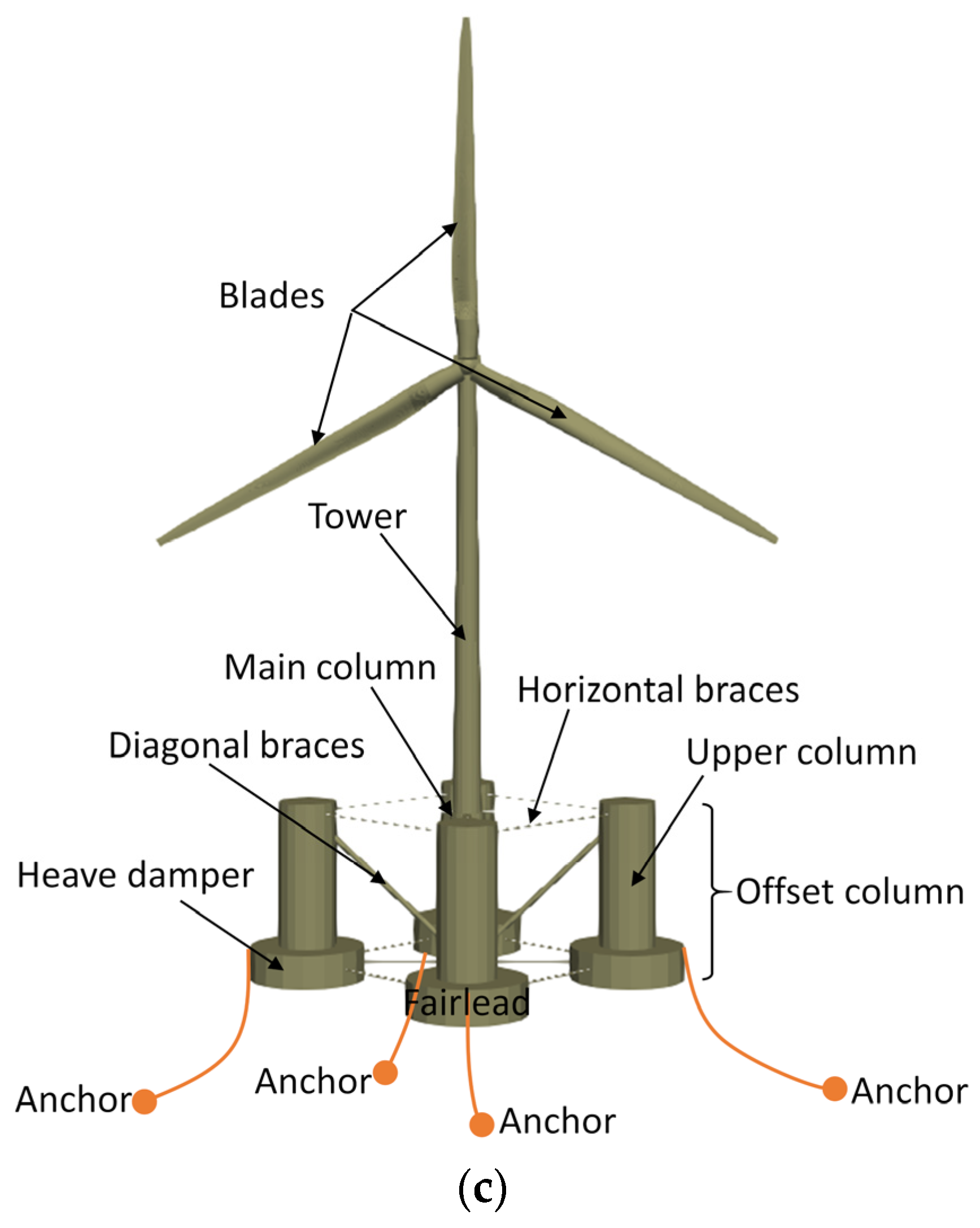
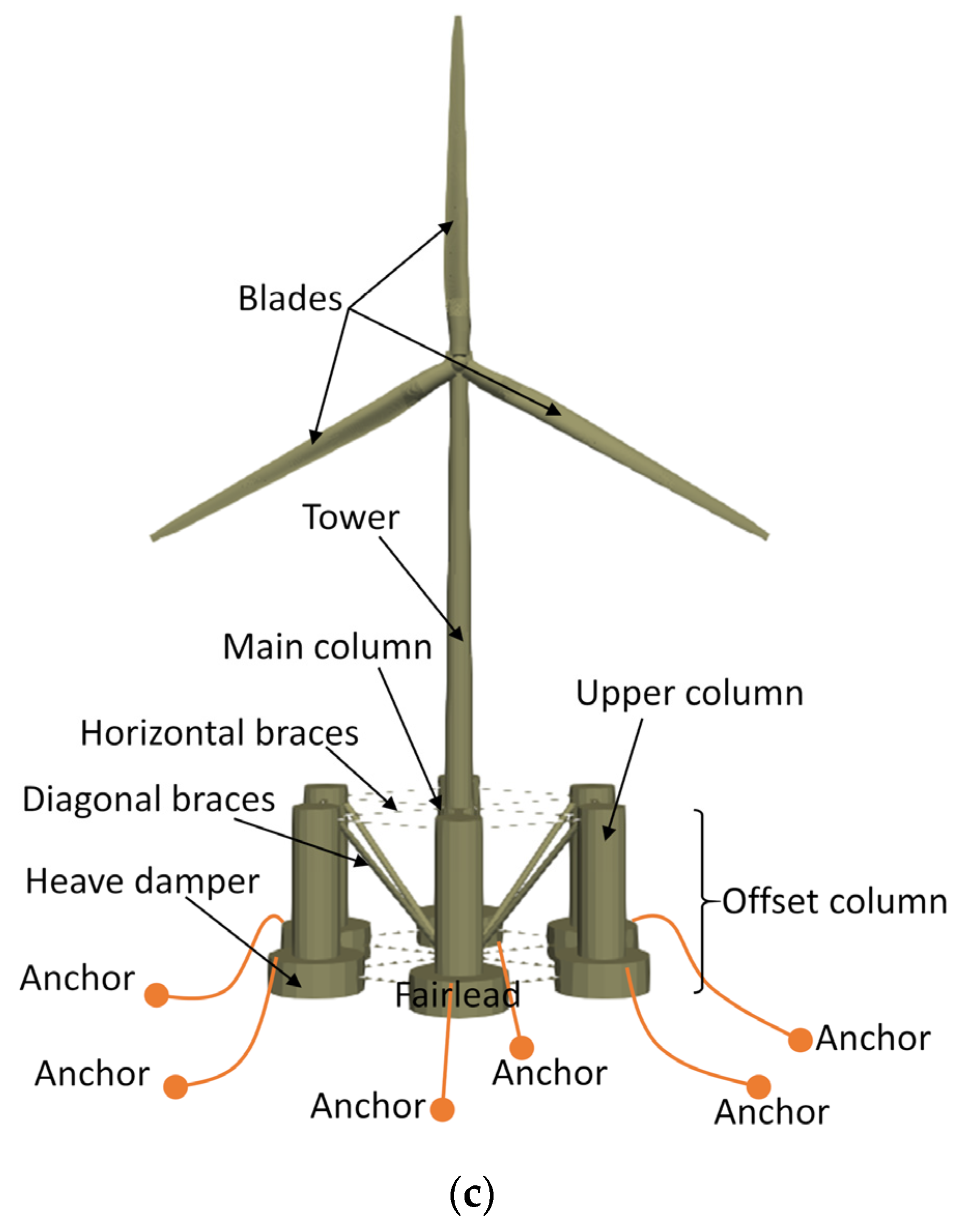
20], which is another concept of FOWT. It relies on large columns linked by braces to maintain stability, showing good wave-resistance ability.
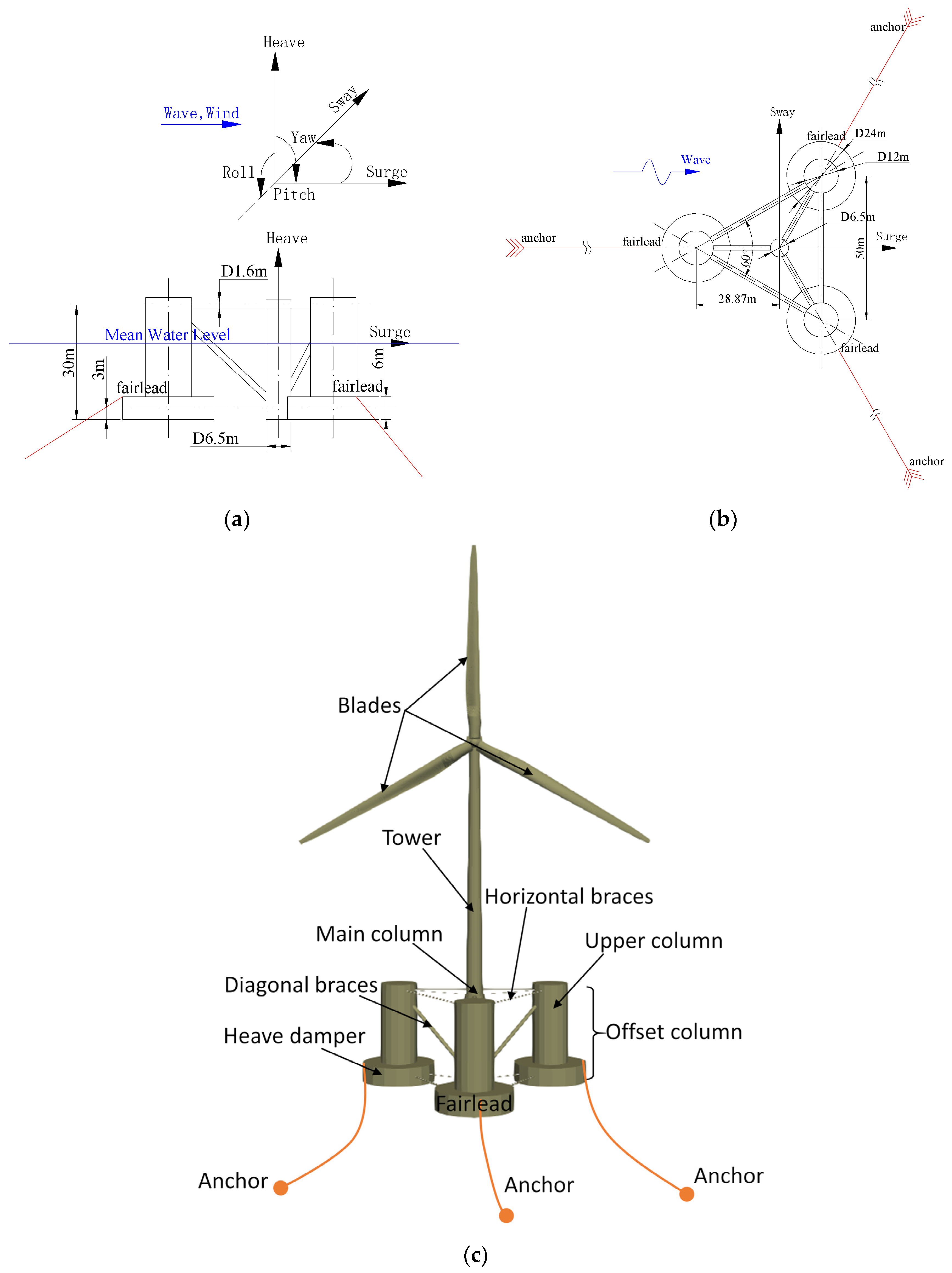
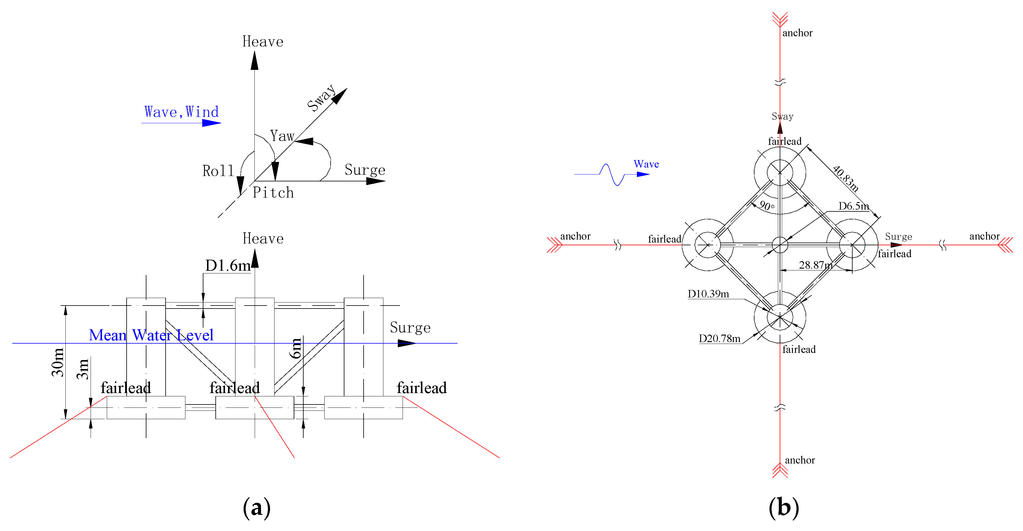
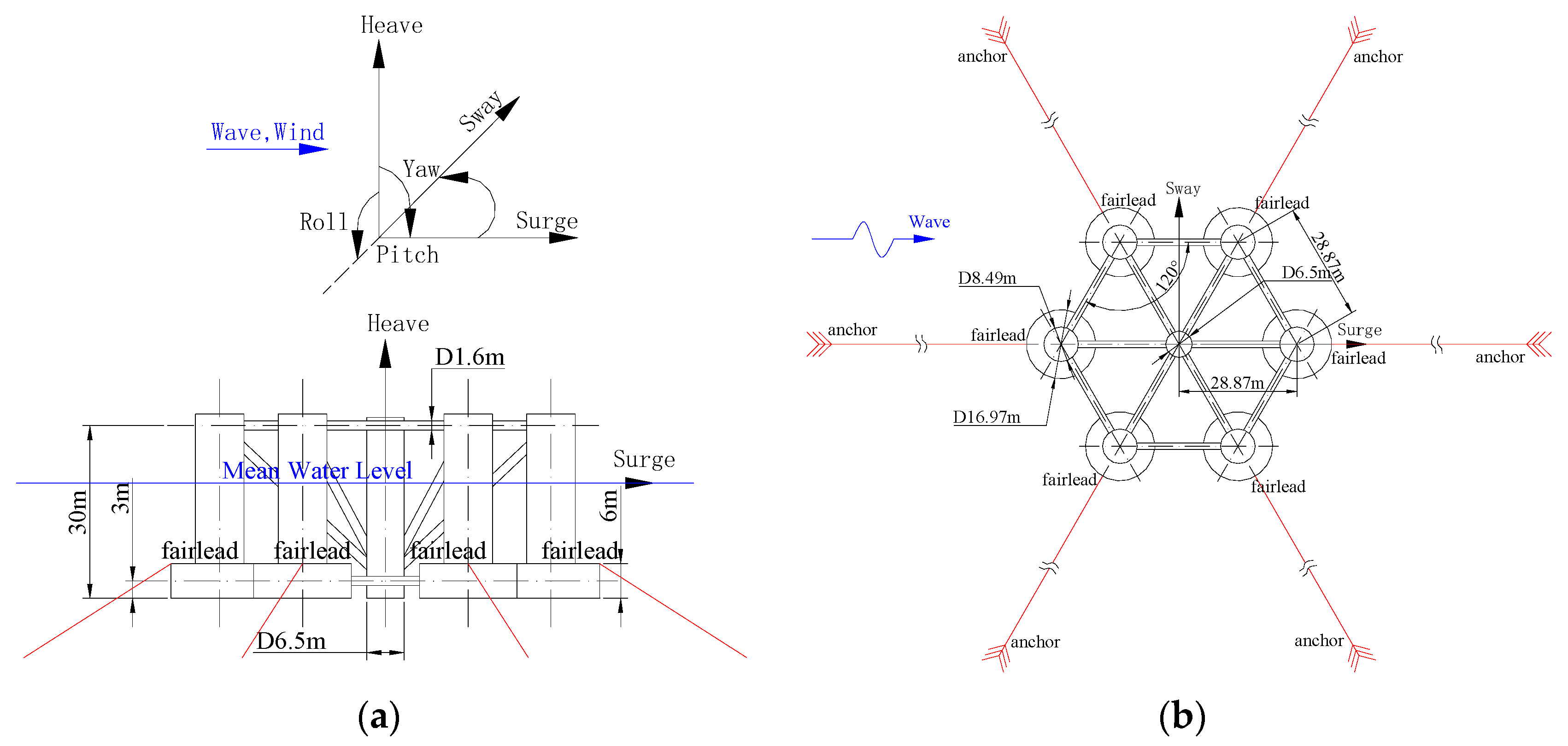
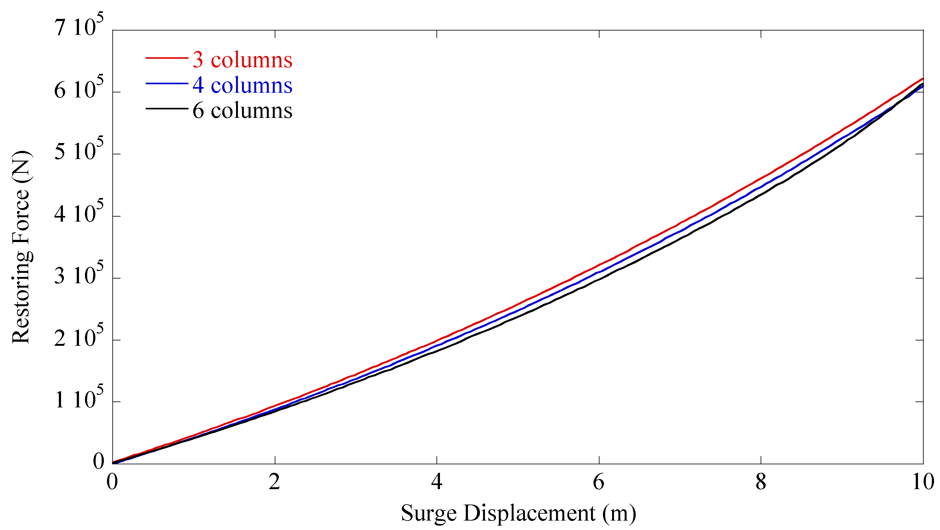
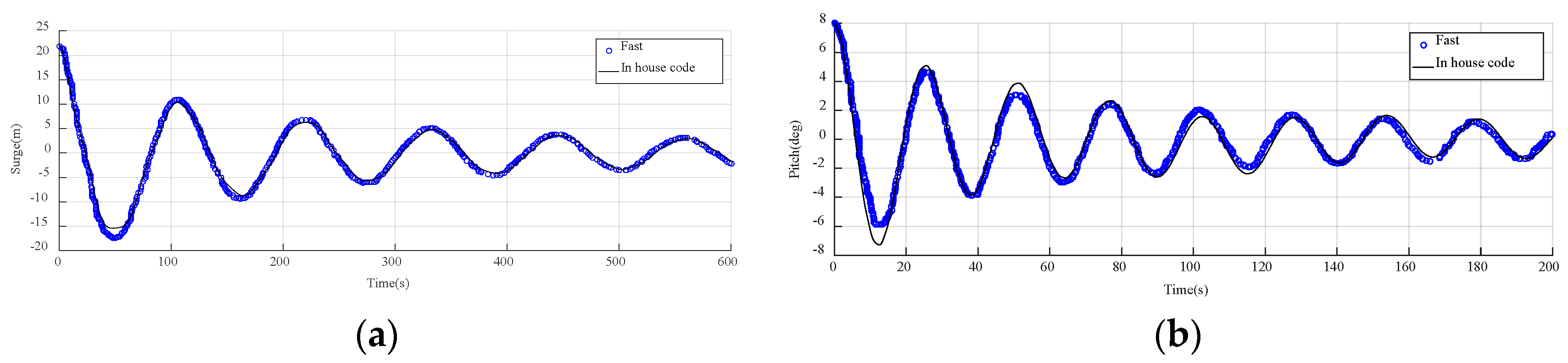
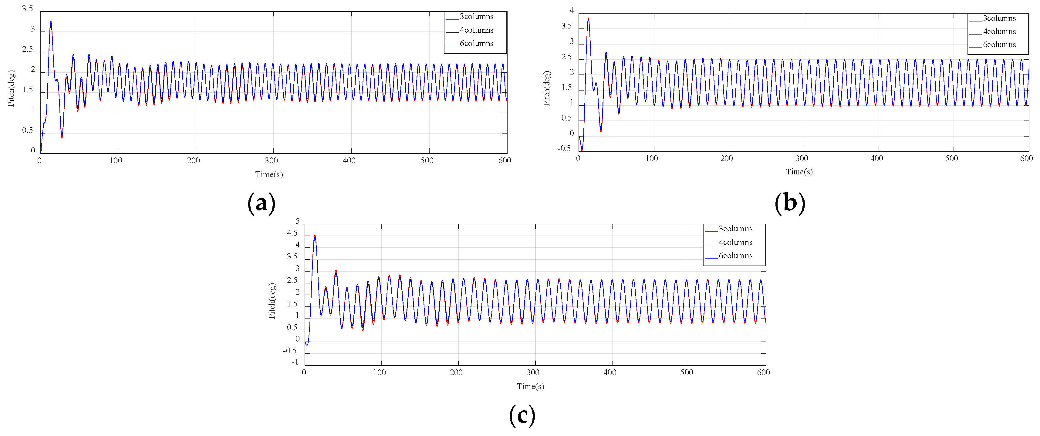
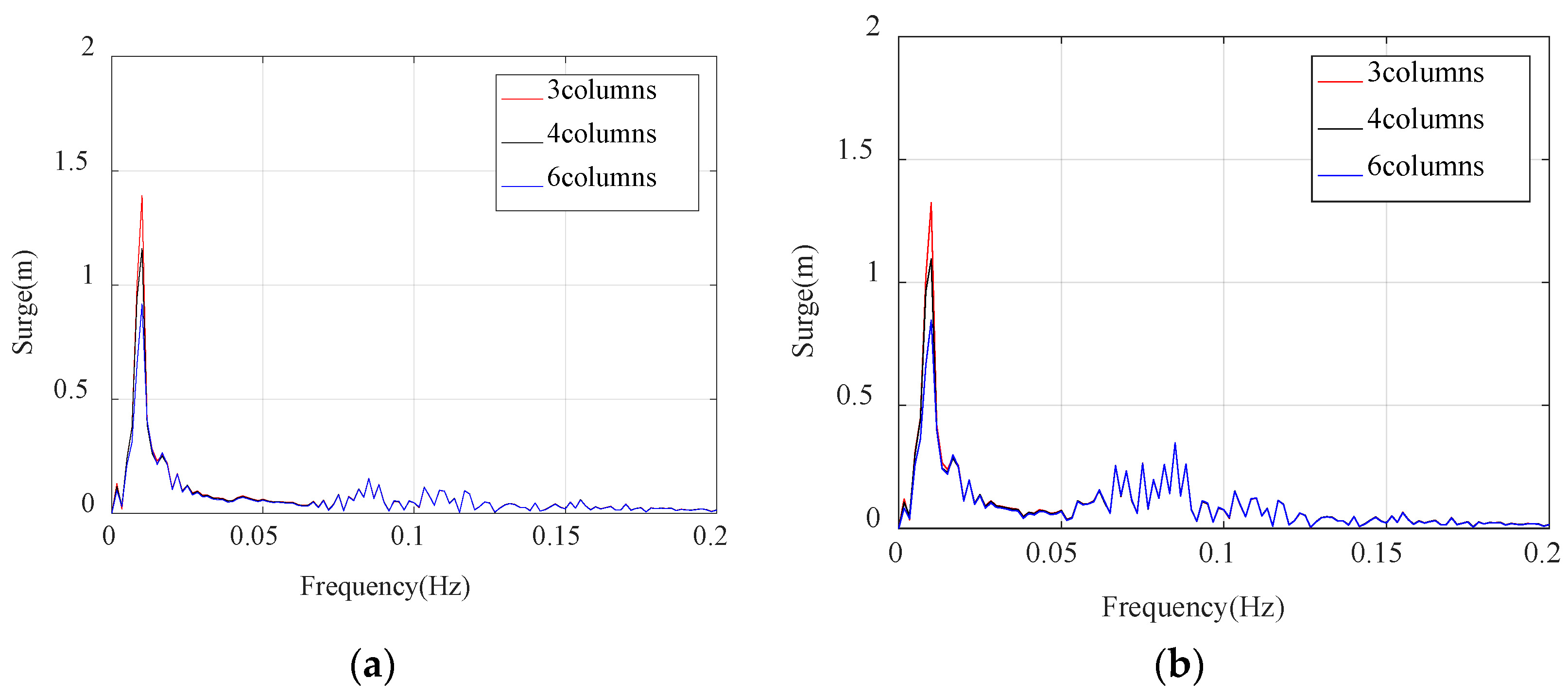
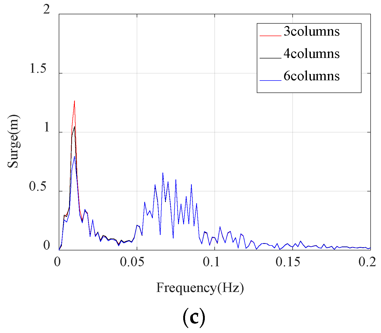
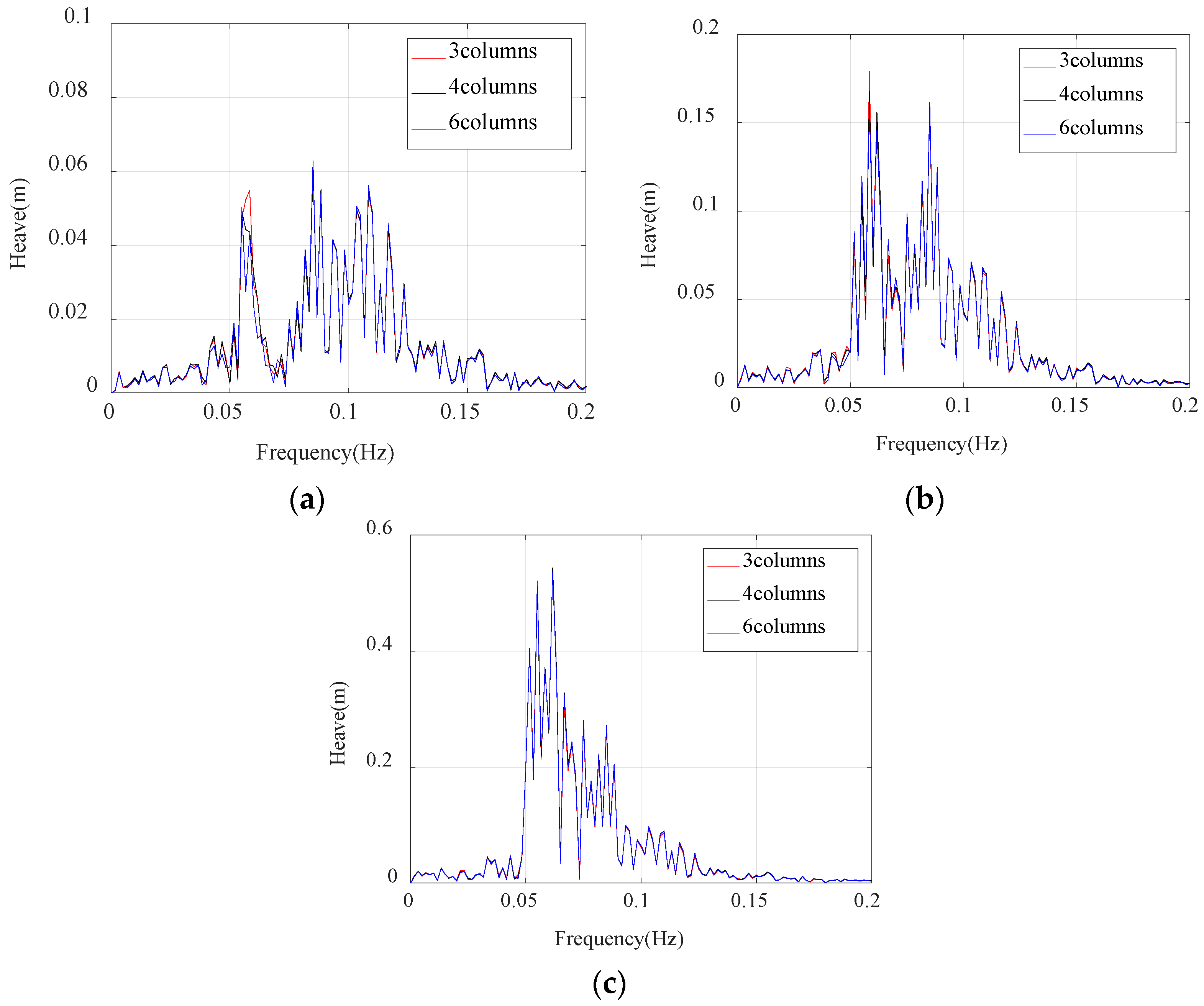
In this paper, a modification based on the original DeepCwind semi-submersible FOWT is carried out, in which the number of the floating columns is changed but the total weight remains unchanged. The calculations are performed using fully coupled in-house codes, and the results are analyzed to reveal the effects of the number of the floating columns to the dynamic response of the DeepCwind semi-submersible FOWT. Section 2 introduces the quasi-static theory of the mooring system and the calculation of the dynamics of the platform structure using the potential flow theory. Section 3 describes the details about the wind turbine, floating platforms, and mooring systems. In Section 4, the dynamic response of the FOWT is studied, and the effects from the number of the floating columns is obtained.

2. FOWT Coupled Dynamics Theory

From the development process of wind turbines, it can be found that the initial environmental load on the onshore wind turbine is mainly the wind load acting on the wind turbine blades. For fixed bottom wind turbines operating in shallow water offshore areas, in addition to being subjected to wind loads, the support structure is also subjected to hydrodynamic loads. However, for the FOWT studied in this article, the situation is more complicated. In addition to those forces already listed, wind loads acting on the wind turbine blades are transmitted to the floating platform through the rotor-nacelle components and towers; at the same time, the mooring tension received by the mooring system is also transmitted to the floating platform. These affect the dynamic response of the floating platform. On the other hand, the movement of the floating platform in turn causes relative motion between the platform and the wind turbine blades, affecting the aerodynamic forces on the blades. The reactions between the various components of the structure are complex and coupled, making the dynamic response of FOWT difficult to predict and full of challenges. The blades–tower–platform coupling system is non-linear, which is different from the traditional structures. The high-frequency effects have not been considered in this paper. Instead, this research considers the wind turbine tower as a rigid body, and only the platform’s six degrees of freedom are considered to calculate the low-frequency response of the platform. In the following, the theories for calculating the mooring system and the platforms are briefly introduced.

2.1. Mooring System

The solution to the analytical equation of the catenary between the two fixed points has been thoroughly studied, and many practical solutions have been obtained [35,36]. For the mooring line of a floating wind turbine, due to the uniform thickness and mass distribution of the cable, no horizontal force acts on the line between the anchor and the fairlead [37]. During the working process, the mooring line may be partially shelved on the seabed. When the shelf length is zero, the entire mooring line is in the water. If a portion of the mooring line rests on the seabed, the analytical equation is as follows:
x F ( F H ,   F V ) = L F V ω + F H ω ln [ F V F H + 1 + ( F V F H ) 2 ] + F H L E A + C B ω 2 E A [ ( L F V ω ) 2 + ( L F V ω F H C B ω ) max ( L F V ω F H C B ω , 0 ) ]
z F ( F H ,   F V ) = F H ω [ 1 + ( F V F H ) 2 1 + ( F V ω L F H ) 2 ] + 1 E A ( F V L ω L 2 2 )
where, x F and z F are the cable profile in horizontal and vertical planes at distance s along the line, respectively; FH and FV are the horizontal and vertical components of the effective tension in the mooring line at the fairlead [38]; EA is the cross–section axial stiffness; L denotes the upstretched line length; CB is the coefficient of static friction between the seabed and the mooring line; ω = gA(ρcρ) is the weight per unit length in the submerged fluid; ρc is the cable density, ρ means the fluid density; and g is the acceleration due to gravity. It is worth noting that Equations (1) and (2) are established in the local coordinate system and can be solved by an iterative method.

2.2. Platform

For the entire nonlinear system, all forces acting on the entire structure should be balanced. For floating platforms, the received external forces mainly include platform gravity, hydrodynamics, and mooring line tension of the mooring system. This part shows the forces modeled in in-house code when using a potential flow theory approach. The forces and added mass are applied at the platform reference point in the theory. The potential flow theory is used to calculate hydrodynamics and is expressed as follows [33]:
F W R P ( x ) = F W ( x ) + F H S ( x ) + F R D ( x ) + F A M ( x )
in which,
F A M ( x ) = A M R a p
F W ( x ) = 1 N k = N 2 1 N 2 W [ k ] 2 π Δ t S ζ 2 s i d e d ( ω 0 ) X ( ω 0 , β ) | ω 0 = k Δ ω e j 2 π k n N
F H S ( x ) = ρ g V 0 δ 3 C H y d r o s t a t i c x
F R D ( x ) = 0 t K ( t τ ) x ˙ j ( τ ) d τ
where, F W R P ( x ) is the total load at the platform reference point; F W ( x ) is the incident-wave excitation force at the platform reference point; F H S ( x ) is the hydrostatic force at the reference node; F R D ( x ) is the radiation memory-effect force at the reference point; and F A M ( x ) is the total added mass force from all contributions.
The terms of the general equation are discussed separately. A M R is the added-mass due to radiation at the reference point; a p is the linear acceleration of the structure; W [ k ] is the Fourier transform of a white noise time series with zero mean and unit variance; S ζ 2 s i d e d ( ω 0 ) is the desired power spectral density of the wave elevation per unit time, this paper uses the P–M spectrum; X ( ω 0 , β ) is wave-excitation force array normalized per unit wave amplitude; ω 0 is the frequency; β is the incident wave direction angle; j is the number of degrees of freedom (DOF); n is the discrete-time-step counter; k is the discrete-frequency-step counter; N is the number of discrete steps; ρ g V 0 δ 3 is the buoyancy and equals the platform weight; V 0 is the volume of the immersed part of the platform; δ 3 is the component of the Kronecker–Delta function; C H y d r o s t a t i c is the hydrostatic-restoring matrix; x is the platform motion; t is time; K is the radiation kernel from potential flow theory; and x ˙ ( τ ) is the platform velocity. The details of this method can be referred in the study by Jonkman [33].
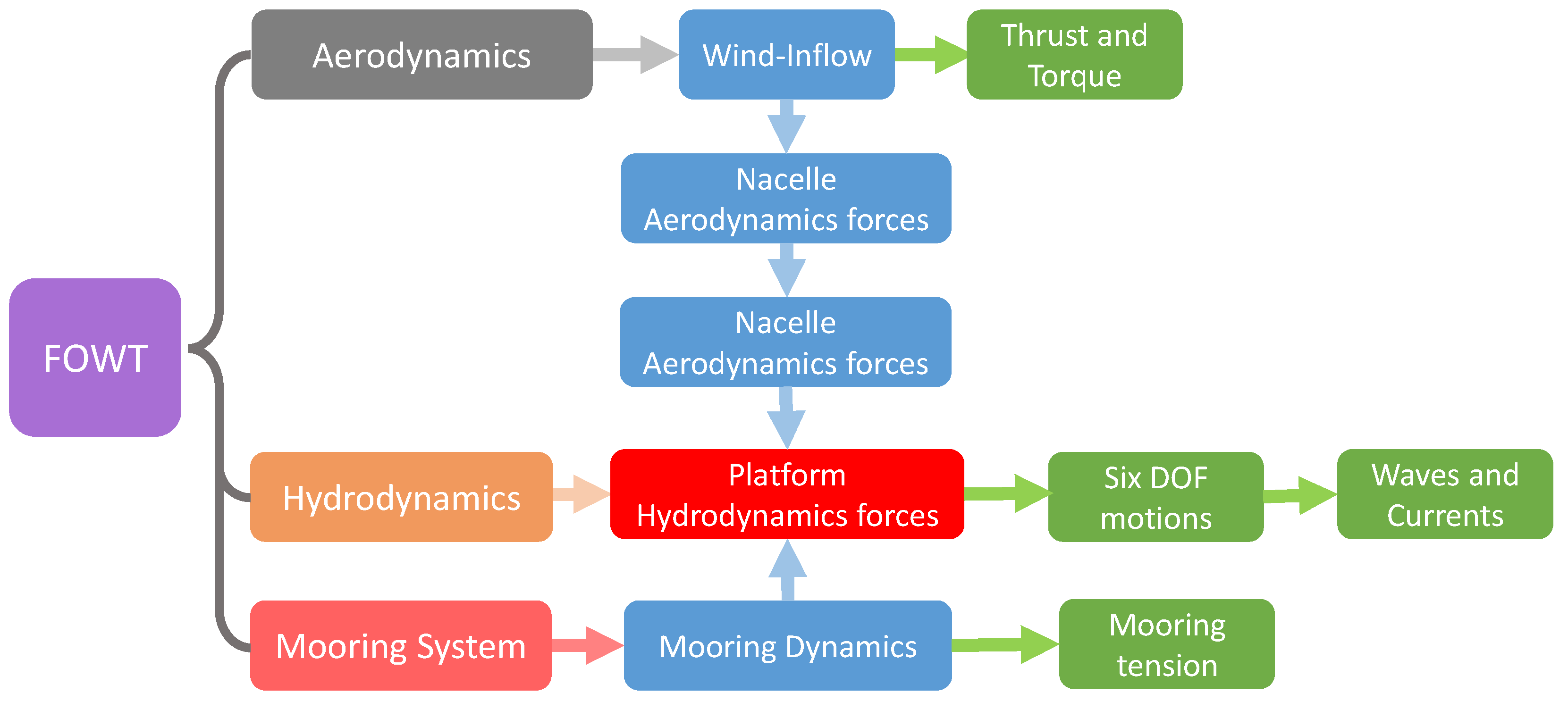
Based on the theories introduced above, a program for coupling computation of the FOWT was developed in this work. The coupled dynamic response of FOWT consists of three parts, namely the aerodynamics of the wind turbine, the hydrodynamics of the floating platform, and the response of the mooring system. Since this paper mainly studies the dynamic response of floating platforms with different structural forms under the condition of the number of offset columns, only the calculation theory of the latter two parts with more important influences is considered. Figure 1 shows the structure of the in-house developed code, consisting of the calculations of the wind inflow, aerodynamics, waves, sea current, hydrodynamics, and dynamics of the floater.
We regard the tower as a rigid body and only the low-frequency response of the platform with six degrees of freedom is studied. The high-frequency responses of the system, such as the high-frequency vibrations of the blade and the tower, are not considered. Therefore, the turbine–tower interaction is not taken into consideration in the present research.

3. Semi-Submersible FOWT

3.1. Wind Turbine

In this paper, the blades of the wind turbine are considered to be nearly rigid while the flexibility of the tower is taken into consideration, in which the forward, backward, and lateral mode shapes of the tower along the external force are adopted. The tower base is located 10 m above from the Mean Water Level (MWL). The key parameters of the component geometry and the mass of the NREL 5 MW wind turbine are listed in Table 1. More details can be found in the studies by Jonkman et al. [33]. The aerodynamic forces of this wind turbine, including those induced by the rotor-nacelle, the blades, and the tower, as well as the structural deflections, are all calculated through the corresponding modules of the in-house program.

3.2. Floating Platform

The possibilities and benefits of the DeepCwind semi-submersible structure [20] used as a support platform have been elaborated above, and they have received extensive demonstration and experimental testing in the OC4 project. The schematic diagram of the semi-submersible floating platform prototype is shown in Figure 2, which consists of a small diameter main column connected to the bottom of the tower at the top, three large diameter offset columns surrounding the main column, and a series of smaller diameter tubular bracing members connecting the main and offset columns. The cylindrical heave damper is attached to the bottom of the upper columns to increase the vertical stiffness of the platform to prevent excessive vertical vibration of the platform during the movement. The entire platform’s columns are partially submerged in water, and the upper part is exposed to the air. The initial draft is designed to be 20 m deep. The platform is moored with three catenary mooring lines. The top end of each mooring line is attached to a fairlead on top of a cylindrical heave damper of a biasing column. Similar to barges, the semi-submersible platform relies primarily on the water-plane area to maintain good stability. However, unlike the barge, it also has a fairly deep draft area, which is difficult to achieve on a barge, which can further ensure the stability of the platform [39]. At the same time, a number of elongated supports are used to connect the columns and to increase the stiffness. The geometric properties of the semi-submersible platform are listed in Table 2. More details can be found in the study by Robertson et al. [20].
Keeping the structural weight and the volume of the floating platform as constants, the number of offset columns are systematically changed from 3 to 4 then 6. The floating platform prototype is named Model 0, which is a 3-column form. The 4-column floating platform, named Model 1 and shown in Figure 3, consists of four columns (one central vertical column and four offset columns) and 20 supports (four top diagonal tubular bracing members, four top horizontal tubular bracing members, four bottom diagonal tubular bracing members, four bottom horizontal tubular bracing members); all columns and supports are cylindrical. The 6-column floating platform, named Model 2 and shown in Figure 4, includes seven columns (one central vertical column and six offset columns) and 30 supports (the support distribution form is similar to the 4-column form, and the number is increased accordingly). For the three different structural forms of the platform in this paper, we want to only change the number of the columns but keep the weight and the volume as constants. Therefore, the diameter and wall thickness of the columns can be calculated accordingly.

3.3. Mooring System

In order to ensure that the position of the semi-submersible floating platform under external force does not deviate too much, the position of the platform is fixed and maintained by the mooring system. For the mooring system of the platform structure studied in this paper, the fairleads of the mooring lines are located at the top of the cylindrical heave damper, 14.0 m below the mean sea level and horizontally 40.87 m away from the centerline of the platform. In order to meet the ballast requirements of floating platforms, there are many types of ballasts to choose from, taking into account a variety of factors, this paper uses water (density = 1025 kg/m3) for ballast. The ballast water of the upper column does not fill the entire column, but fills up to 6.17 m below the MWL (mean water level), and the ballast water of the cylindrical heave damper is also not full, but is 0.8922 m from the top. There is no water ballast in the horizontal or diagonal tubular bracing members, cross braces, or main column. When the number of the offset columns is changed, the number of the mooring lines will be increased while the diameter of the mooring line will be decreased to keep the weight of the mooring lines as a constant. The details of the parameters for the mooring system are given in Table 2.
We have designed the mooring system to have the same stiffness. Therefore, the number of mooring lines has the least impact on the FOWT natural frequency. The restoring force of the mooring system as a function of the motion in the surge direction for the three platforms is shown in Figure 5.

3.4. Load Conditions

In order to study the dynamic response of a DeepCwind semi-submersible FOWT in different configurations, several load conditions shown in Table 3 and Table 4 were examined, including three regular wave load conditions (LC1–LC3), three irregular wave load conditions (LC4–LC6), and a windless free-decay condition test was performed in advance (LCI–LCIII).

3.5. Basic Comparison with Fatigue, Aerodynamics, Structures, and Turbulence (FAST) and the Experiment

Since an in-house developed code is applied, it is necessary to check the code in advance. The fully coupled aero-hydrodynamic simulation of the full-scale DeepCwind prototype model under the same conditions was performed using the present program, FAST software, and corresponding test data. Figure 6 shows the comparison in the surge and pitch directions using different solvers under the free-decay conditions LCI and LCIII. In general, the in-house code results show good agreement with the those by FAST, which are also available in a numerical study [40]. The results of the code is further compared with the available OC4 FOWT experimental data [41], as shown in Figure 7. Good agreement is achieved. The details of the settings of the OC4 FOWT experiment can be referred to in the study by Ishihara and Zhang [41].

4. Results and Discussion

4.1. Free Decay

The free-decay test of surge, heave, and pitch motions was performed because it can effectively predict the natural frequency and damping ratio of the floating structure. The former is one of the main hydrodynamic properties and it is also an important parameter of this paper. In particular, the dynamic response of the surge, heave, and pitch motions are always the major components. It should be noted also that in the free-decay test, the inflow wind speed and aerodynamic load are not included. Only the calculation of the hydrodynamic load, the mooring system, and the rigid body dynamics are considered. At the beginning of the test, an initial displacement is applied to the platform. The initial displacement here is generalized and then released. The platform will return to the equilibrium position by the restoring force, then reciprocate, and will eventually become stationary.
Through the data obtained by the free-decay test as shown in Figure 8 and using FFT (Fast Fourier Transform), it can be calculated that the natural periods of the 3, 4, and 6 offset-column platforms for the surge motion are 113.6 s, 104.8 s, and 90.1 s, respectively, while the natural periods for the heave and pitch motions do not show obvious differences.

4.2. Regular Waves

Since the floating wind turbine operates in a marine environment, the platform is subjected to waves, resulting in periodic motion. It is well known that the waves acting on a floating platform are very complex, the low-order waves will cause the platform to vibrate in the same period near the initial position, while the higher-order waves cause the platform to move in the direction of the wave [42]. In addition, because the platform is limited by the mooring system, it will oscillate near the equilibrium position after a period of time. Considering that the surge, heave, and pitch motions of the floating platform are the most obvious motions, these three components are then selected to be examined, as shown in Figure 9, Figure 10 and Figure 11. Since error is inevitable at the beginning of the calculation, the statistics are therefore from 400 s to 600 s when the stable oscillation has been achieved. The statistics of foundation motions in the time domain are provided in Table 5.
It can be found that with an increasing number of offset columns, the maxima of the surge response gradually decrease, see Figure 9. Likewise, the minima and averages also have the same pattern. For example, in LC2, when the number of offset columns is changed from 3 to 6, the maximum surge is reduced from 6.16 m (Model0) to 5.88 m (Model1) and 5.26 m (Model2), while the minimum surge is reduced from 3.17 m (Model0) to 2.94 m (Model1) and 2.49 m (Model2). Comparing the three load conditions LC1–LC3, it can be found that the maximum value of the surge response increases slightly due to the increase of wave height and period. Under the same load condition, with the increase of the number of offset columns of the floating platform structure, the maximum value of the surge response still gradually decreases. It should be pointed out that the amplitude of the surge motion is also decreased as increasing the number of the columns. The amplitude surge motion of the 3, 4, and 6-columns platform is 0.69 m, 0.64 m, and 0.55 m, respectively, for LC1. While for LC2, the amplitude surge motion is decreased from 1.46 m (3 columns), to 1.44 m (4 columns) and 1.41 m (6 columns). For LC3, it is 2.61 m (3 columns), 2.57 m (4 columns), and 2.52 m (6 columns). The surge amplitude will affect the aerodynamic load and dynamic response of the whole system due to the additional relative wind speed caused by the surge motion, as a result, a small variation of hydrodynamic load due to these surge amplitude motions will be introduced, which has been discussed in detail in the studies by Vaal et al. [43] and Tran et al. [44].
For the heave motion, the amplitude is relatively small, basically in between 0 m and 1 m, as shown in Figure 10. For LC1, when the number of columns is 3, the maximum value is positive, but close to 0. If the number of columns increases to 4, the maximum decreases slightly. Different from the surge response, the minimum of the heave response is negative. For the mean value, the same trend as the surge motion is found.
As shown in Figure 11, although the pitch amplitudes of the three models are different, the average values are relatively stable. The average pitch is around 1.73 deg for the 3-offset columns platform, while the average pitch of the 4-offset columns platform and 6-offset columns platform are, respectively, about 1.75 deg and 1.76 deg, indicating that the number of the offset columns has little effect on the pitch motion.

4.3. Irregular Waves

For irregular wave conditions, the P–M spectrum was used and the analysis was performed in the frequency domain. The curves in Figure 12, Figure 13 and Figure 14 show the magnitudes of each motion component. Representative response amplitudes are summarized in Table 6.
From the results in the frequency domain, it can be found that the surge has an obvious low-frequency response peak value, and at this frequency the magnitudes of the three different platforms are significantly different, as shown in Figure 12. By comparing the three load conditions LC4–LC6, it can be further found that as the irregular wave height and the period increase, the amplitude of the responses also decreases. Importantly, the subsequent high-frequency response shows a large range. As the number of offset columns increases, the structure will peak at almost the same frequency with gradually decreased amplitudes. When the number of offset columns is 6, the decrease in the surge amplitudes is the most obvious, reaching nearly 70% that of Model0.
As plotted in Figure 13, there is no obvious low-frequency peak similar to the surge response in the spectra of the heave responses. Comparing the three loads conditions LC4–LC6, the significant influence on the heave response is from the height and period of the wave, although the amplitude is small. In addition, different from the surge motion, there are two peaks in the whole frequency range, while the representational area is continuous, and it is difficult to accurately distinguish them.
The trend of the response amplitude of the pitch motion shown in Figure 14 is similar with the other two responses described above. As can be further found from the spectra, the response amplitude shows no significant peak. Comparing the results of the heave, surge, and pitch responses, it can be found that the peak of the low frequency response appears at different frequencies, the former is about 0.058 Hz, the latter two are nearly 0.01 Hz, indicating that the coupling between the heave response and the surge or pitch responses is weak.

5. Conclusions

In this study, a semi-submersible floating platform with different numbers of offset columns but with the same total weight based on the DeepCwind prototype is proposed. Importantly, by increasing the number of offset columns, the dynamic performance of surge, heave, and pitch motions improve, especially for the surge component. The following summarizes the detailed findings in this study.
(1)
Through the free-decay test, the in-house developed code is found to be satisfactorily accurate, which can be used for the calculations about the semi-submersible floating offshore wind turbines.
(2)
The free-decay test shows that increasing the number of offset columns can reduce the natural period in the surge mode, while the natural period of the heave and pitch modes do not change significantly.
(3)
The regular wave-load test shows that when the number of offset columns of the floating platform increases, the surge motion decreases, while the effects of the column numbers is negligible for the heave and pitch motions. When the number of offset columns is six, the decreasing in the surge motion is the most obvious, reaching nearly 80% that of the model with three offset columns.
(4)
For the irregular wave load, as the number of offset columns increases, the responses of surge, heave, and pitch decrease, and similar to the regular wave loads, the most obvious influence from the increased column number is in the surge direction. When the number of offset columns is six, the decreasing in the surge amplitudes is the most obvious, reaching nearly 70% of that of the model with three offset columns.

Supplementary Files

Supplementary File 1

Author Contributions

Conceptualization, Z.L. and Y.F.; methodology, Y.F.; software, Y.F.; validation, Y.F.; writing—original draft preparation, Y.F.; writing—review and editing, Z.L. and Y.F.; supervision, Z.L.; guidance, Z.L; coding, W.W and G.Q.

Funding

The study was funded by National Key Research and Development Plan of China (2016YFE0127900) and the National Natural Science Foundations of China (51608220).

Acknowledgments

The corresponding author sincerely thanks Huazhong University of Science and Technology for the support to this research.

Conflicts of Interest

The authors declare no conflict of interest.

Nomenclature

A M R Added mass due to radiation at the reference point
a p Linear acceleration of the structure (m·s−2)
CBCoefficient of static friction between the seabed and the mooring line
C H y d r o s t a t i c Hydrostatic-restoring matrix
DOFDegrees of freedom
EACross-section axial stiffness (kN)
FASTFatigue, Aerodynamics, Structures, and Turbulence
F A M Total added mass forces from all contributions (kN)
FHHorizontal components of the effective tension in the mooring line at the fairlead (kN)
F H S Hydrostatic forces at the reference node (kN)
FOWTFloating offshore wind turbine
F R D Radiation memory-effect force at the reference point (kN)
FVVertical component of the effective tension in the mooring line at the fairlead (kN)
F W A P Total loads at the platform reference point (kN)
gAcceleration due to gravity (m·s−2)
jNumber of DOF
kDiscrete-frequency-step counter
K Radiation kernel from potential flow theory
KijWave radiation-retardation kernel matrix
LUnstretched line length (m)
LCLoad condition
MWLMean water level
nDiscrete-time-step counter
NRELNational Renewable Energy Laboratory
OC3Offshore code comparison collaboration
OC4Offshore code comparison collaboration continuation
S ζ 2 s i d e d ( ω ) Desired power spectral density of the wave elevation per unit time, this paper uses the P–M spectrum
tTime (s)
TLPTension leg platform
V0Displaced volume of the immersed part of the platform (m3)
W [ k ] Fourier transform of a white noise time series with zero mean and unit variance
xPlatform motions (m)
x ˙ ( τ ) Platform velocity (m·s−1)
xFCable profile in the horizontal planes at distance s along the line (m)
X ( ω , β ) Wave-excitation force array normalized per unit wave amplitude ( kN · m 1 )
zFCable profile in the vertical planes at distance s along the line (m)
βIncident wave direction angle (degree)
δ3Component of the Kronecker–Delta function
ρFluid density (kg m−3)
ρcCable density (kg/m3)
ω ω = gA (ρcρ), Weight per unit length in the submerged fluid (N/m)
ω 0 Frequency (Hz)

References

  1. Zhang, M.-F.; Deng, K.; Chen, B.; Wang, S.; Gao, T.; Fang, Z.; Wang, S.-C. Status and development of chinese wind power industry. Jidian Gongcheng Mech. Electr. Eng. Mag. 2010, 27, 1–3. [Google Scholar]
  2. Archer, C.L.; Jacobson, M.Z. Evaluation of global wind power. J. Geophys. Res. Atmos. 2005, 110. [Google Scholar] [CrossRef] [Green Version]
  3. Henderson, A.R.; Witcher, D. Floating Offshore Wind Energy—A Review of the Current Status and an Assessment of the Prospects. Wind Eng. 2010, 34, 1–16. [Google Scholar] [CrossRef]
  4. Butterfield, S.; Musial, W.; Jonkman, J.; Sclavounos, P. Engineering Challenges for Floating Offshore Wind Turbines; National Renewable Energy Lab. (NREL): Golden, CO, USA, 2007.
  5. Bachynski, E.E.; Moan, T. Design considerations for tension leg platform wind turbines. Mar. Struct. 2012, 29, 89–114. [Google Scholar] [CrossRef]
  6. Jonkman, J.M.; Matha, D. Dynamics of offshore floating wind turbines—Analysis of three concepts. Wind Energy 2011, 14, 557–569. [Google Scholar] [CrossRef]
  7. Sclavounos, P. Floating Offshore Wind Turbines. Mar. Technol. Soc. J. 2008, 42, 39–43. [Google Scholar] [CrossRef]
  8. Sorensen, J.N.R.; Shen, W.Z. Numerical modeling of wind turbine wakes. J. Fluids Eng. 2002, 124, 393–399. [Google Scholar] [CrossRef]
  9. Skaare, B.; Nielsen, F.G.; Hanson, T.D.; Yttervik, R.; Havmøller, O.; Rekdal, A. Analysis of measurements and simulations from the Hywind Demo floating wind turbine. Wind Energy 2015, 18, 1105–1122. [Google Scholar] [CrossRef]
  10. Floating Wind Farm to Be Installed off Peterhead. Available online: https://www.bbc.com/news/uk-scotland-scotland-business-34694463 (accessed on 23 March 2019).
  11. Liu, Y.; Xiao, Q.; Incecik, A.; Peyrard, C.; Wan, D. Establishing a fully coupled CFD analysis tool for floating offshore wind turbines. Renew. Energy 2017, 112, 280–301. [Google Scholar] [CrossRef] [Green Version]
  12. Heronemus, W.E. Pollution-Free Energy from Offshore Winds. In Proceedings of the 8th Annual Conference and Exposition Marine Technology Society, Washington, DC, USA, 11–13 September 1972. [Google Scholar]
  13. Neville, A. Hywind Floating Wind Turbine. Power 2009, 153, 40. [Google Scholar]
  14. Koh, J.; Robertson, A.; Jonkman, J.; Driscoll, F.; Ng, E. Building and calibration of a fast model of the sway prototype floating wind turbine. In Proceedings of the International Conference on Renewable Energy Research and Applications (ICRERA), Madrid, Spain, 20–23 October 2013; pp. 20–23. [Google Scholar]
  15. Sethuraman, L.; Venugopal, V. Hydrodynamic response of a stepped-spar floating wind turbine: Numerical modelling and tank testing. Renew. Energy 2013, 52, 160–174. [Google Scholar] [CrossRef]
  16. Bulder, B.; van Hees, M.T.; Henderson, A.; Huijsmans, R.; Pierik, J.; Snijders, E.; Wijnants, G.; Wolf, M. Study to feasibility of and boundary conditions for floating offshore wind turbines. ECN, MARIN, Lagerwey the Windmaster, TNO, TUD, MSC 2002.
  17. Roddier, D.; Cermelli, C.; Aubault, A.; Weinstein, A. WindFloat: A floating foundation for offshore wind turbines. J. Renew. Sustain. Energy 2010, 2, 033104. [Google Scholar] [CrossRef]
  18. Karimirad, M.; Michailides, C. V-shaped semisubmersible offshore wind turbine: An alternative concept for offshore wind technology. Renew. Energy 2015, 83, 126–143. [Google Scholar] [CrossRef]
  19. Beyer, F.; Choisnet, T.; Kretschmer, M.; Cheng, P.W. Coupled MBS-CFD simulation of the IDEOL floating offshore wind turbine foundation compared to wave tank model test data. In Proceedings of the Twenty-Fifth (2015) International Ocean and Polar Engineering Conference, Kona, Big Island, HI, USA, 21–26 June 2015. [Google Scholar]
  20. Robertson, A.; Jonkman, J.; Masciola, M.; Song, H.; Goupee, A.; Coulling, A.; Luan, C. Definition of the Semisubmersible Floating System for Phase II of OC4; National Renewable Energy Lab. (NREL): Golden, CO, USA, 2014.
  21. Adam, F.; Myland, T.; Schuldt, B.; Großmann, J.; Dahlhaus, F. Evaluation of internal force superposition on a TLP for wind turbines. Renew. Energy 2014, 71, 271–275. [Google Scholar] [CrossRef]
  22. Vita, L.; Ramachandran, G.; Krieger, A.; Kvittem, M.I.; Merino, D.; Cross-Whiter, J.; Ackers, B.B. Comparison of Numerical Models and Verification Against Experimental Data, Using Pelastar TLP Concept. In Proceedings of the ASME 2015 34th International Conference on Ocean, Offshore and Arctic Engineering, St. John’s, NL, Canada, 31 May–5 June 2015; p. V009T009A047. [Google Scholar]
  23. Jonkman, J.; Musial, W. Offshore Code Comparison Collaboration (OC3) for IEA Wind Task 23 Offshore Wind Technology and Deployment; National Renewable Energy Lab. (NREL): Golden, CO, USA, 2010.
  24. Larsen, T.J.; Hanson, T.D. A method to avoid negative damped low frequent tower vibrations for a floating, pitch controlled wind turbine. J. Phys. Conf. Ser. 2007, 75, 012073. [Google Scholar] [CrossRef] [Green Version]
  25. Karimirad, M.; Gao, Z.; Moan, T. Dynamic motion analysis of catenary moored spar wind turbine in extreme environmental condition. In Proceedings of the European Offshore Wind Conference, EOW2009, Stockholm, Sweden, 14–16 September 2009. [Google Scholar]
  26. Driscoll, F.; Jonkman, J.; Robertson, A.; Sirnivas, S.; Skaare, B.; Nielsen, F.G. Validation of a FAST model of the statoil-hywind demo floating wind turbine. Energy Procedia 2016, 94, 3–19. [Google Scholar] [CrossRef]
  27. Myhr, A.; Maus, K.J.; Nygaard, T.A. Experimental and computational comparisons of the OC3-HYWIND and Tension-Leg-Buoy (TLB) floating wind turbine conceptual designs. In Proceedings of the Twenty-first International Offshore and Polar Engineering Conference, Maui, HI, USA, 19–24 June 2011. [Google Scholar]
  28. Nielsen, F.G.; Hanson, T.D.; Skaare, B.R. Integrated dynamic analysis of floating offshore wind turbines. In Proceedings of the 25th International Conference on Offshore Mechanics and Arctic Engineering, Hamburg, Germany, 4–9 June 2006; pp. 671–679. [Google Scholar]
  29. Shin, H. Model test of the OC3-Hywind floating offshore wind turbine. In Proceedings of the Twenty-First International Offshore and Polar Engineering Conference, Maui, HI, USA, 19–24 June 2011. [Google Scholar]
  30. Statoil. World’s First Floating Wind Farm Has Started Production. Available online: https://www.equinor.com/en/news/worlds-first-floating-wind-farm-started-production.html (accessed on 23 March 2019).
  31. Liu, Y.; Li, S.; Yi, Q.; Chen, D. Developments in semi-submersible floating foundations supporting wind turbines: A comprehensive review. Renew. Sustain. Energy Rev. 2016, 60, 433–449. [Google Scholar] [CrossRef]
  32. Li, B.; Liu, K.; Yan, G.; Ou, J. Hydrodynamic comparison of a semi-submersible, TLP, and Spar: Numerical study in the South China Sea environment. J. Mar. Sci. Appl. 2011, 10, 306. [Google Scholar] [CrossRef]
  33. Jonkman, J.M. Dynamics of offshore floating wind turbines—Model development and verification. Wind Energy Int. J. Prog. Appl. Wind Power Convers. Technol. 2009, 12, 459–492. [Google Scholar] [CrossRef]
  34. Jonkman, J.M. Definition of the Floating System for Phase IV of OC3; National Renewable Energy Lab. (NREL): Lakewood, CO, USA, 2010.
  35. Irvine, H.M.; Irvine, H.M. Cable Structures; MIT Press: Cambridge, MA, USA, 1981; Volume 17. [Google Scholar]
  36. Wilson, J.F. Dynamics of Offshore Structures; John Wiley & Sons: Hoboken, NJ, USA, 2003. [Google Scholar]
  37. Masciola, M. Instructional and Theory Guide to the Mooring Analysis Program; NREL, 2013; Volume 87. Available online: https://nwtc.nrel.gov/system/files/MAP_v0 (accessed on 23 March 2019).
  38. Liu, Y.; Yoshida, S.; Yamamoto, H.; Toyofuku, A.; He, G.; Yang, S. Response Characteristics of the DeepCwind Floating Wind Turbine Moored by a Single-Point Mooring System. Appl. Sci. 2018, 8, 2306. [Google Scholar] [CrossRef]
  39. Robertson, A.N.; Jonkman, J.M. Loads analysis of several offshore floating wind turbine concepts. In Proceedings of the Twenty-First International Offshore and Polar Engineering Conference, Maui, HI, USA, 19–24 June 2011. [Google Scholar]
  40. SIMPACK News Edition July 2013. Available online: http://www.simpack.com/fileadmin/simpack/doc/newsletter/2013/Jul_2013/SN-2013-Jul_all_full-issue_Spreads_HQ150dpi.pdf (accessed on 23 March 2019).
  41. Ishihara, T.; Zhang, S. Prediction of dynamic response of semi-submersible floating offshore wind turbine using augmented Morison’s equation with frequency dependent hydrodynamic coefficients. Renew. Energy 2019, 131, 1186–1207. [Google Scholar] [CrossRef]
  42. Cheng, P.; Wan, D. Hydrodynamic analysis of the semi-submersible floating wind system for phase II of OC4. In Proceedings of the Twenty-Fifth International Ocean and Polar Engineering Conference, Kona, HI, USA, 21–26 June 2015. [Google Scholar]
  43. Vaal, J.; Hansen, M.; Moan, T. Effect of wind turbine surge motion on rotor thrust and induced velocity. Wind Energy 2019, 17, 1105–1121. [Google Scholar]
  44. Toan, T.; Kim, D.; Nguyen, B. Aerodynamic Interference Effect of Huge Wind Turbine Blades with Periodic Surge Motions Using Overset Grid-Based Computational Fluid Dynamics Approach. J. Sol. Energy Eng. 2015, 137, 061003. [Google Scholar] [CrossRef]
Figure 1. Computational procedures for the in-house developed code. Aerodynamics, nacelle dynamics, and tower dynamics interact with each other and are coupled with platform dynamics. DOF = degrees of freedom.
Applsci 09 01255 g001
Figure 2. Sketch of the DeepCwind semi-submersible floating system (Model 0), (a) side view, (b) bird view, and (c) isometric view of the DeepCwind semi-submersible floating platform. The six DOF are defined as surge, sway, heave, roll, pitch, and yaw. For all simulations presented, the direction of wave propagation is aligned with the platform, which is in the surge direction.
Applsci 09 01255 g002
Figure 3. Sketch of the semi-submersible floating system with four offset columns (Model 1), (a) side view, (b) bird view, and (c) isometric view of the semi-submersible floating platform. The six DFO are defined as surge, sway, heave, roll, pitch, and yaw. For all simulations presented, the direction of wave propagation is aligned with the platform, which is in the surge direction.
Applsci 09 01255 g003aApplsci 09 01255 g003b
Figure 4. Sketch of the semi-submersible floating system with six offset columns (Model 2), (a) side view, (b) bird view, and (c) isometric view of semi-submersible floating platform. The six DFO are defined as surge, sway, heave, roll, pitch, and yaw. For all simulations presented, the direction of wave propagation is aligned with the platform, which is in the surge direction.
Applsci 09 01255 g004aApplsci 09 01255 g004b
Figure 5. Restoring force as a function of surge displacement.
Applsci 09 01255 g005
Figure 6. Comparison of the free-decay responses between Fatigue, Aerodynamics, Structures, and Turbulence (FAST) and the in-house developed code. (a) LCI; (b) LCIII.
Applsci 09 01255 g006
Figure 7. Comparison of the sway and yaw responses between the experiment and the in-house developed code. (a) sway; (b) yaw.
Applsci 09 01255 g007
Figure 8. Floating offshore wind turbines (FOWT) platform motions in the free-decay test. (a) LCI; (b) LCII; and (c) LCIII.
Applsci 09 01255 g008
Figure 9. Surge response for all three platforms under wave loadings (a) LC1, (b) LC2, and (c) LC3.
Applsci 09 01255 g009
Figure 10. Heave response curves for all three platforms under wave loadings (a) LC1, (b) LC2, and (c) LC3.
Applsci 09 01255 g010
Figure 11. Pitch response for all three platforms under wave loadings (a) LC1, (b) LC2, and (c) LC3.
Applsci 09 01255 g011
Figure 12. Surge response spectrum for the three platforms under wave loadings (a) LC4, (b) LC5, and (c) LC6.
Applsci 09 01255 g012aApplsci 09 01255 g012b
Figure 13. Heave response spectrum for the three platforms under wave loadings (a) LC4, (b) LC5, and (c) LC6.
Applsci 09 01255 g013
Figure 14. Pitch response spectrum for the three platforms under wave loadings (a) LC4, (b) LC5, and (c) LC6.
Applsci 09 01255 g014
Table 1. Key parameters of the components of the National Renewable Energy Laboratory (NREL) 5 MW wind turbine.
PropertiesValue
Rating5 MW
Rotor orientationUpwind
Configuration3 Blades
Hub height90.0 m
Blade length61.5 m
Rotor mass109,390 kg
Nacelle mass240,000 kg
Tower mass349,390 kg
Table 2. Main parameters of the semi-submersible platform and mooring system.
Parameters3 Columns (Model 0)4 Columns (Model 1)6 Columns (Model 2)
Platform mass, including ballast13,473,000 kg13,473,000 kg13,473,000 kg
Number of mooring lines346
Angle between two adjacent mooring lines120°90°60°
Platform draft20.0 m20.0 m20.0 m
Depth of fairleads below MWL14.0 m14.0 m14.0 m
Centerline spacing between offset columns50.0 m40.8 m28.9 m
Length of upper columns26.0 m26.0 m26.0 m
Length of the cylindrical heave damper6.0 m6.0 m6.0 m
Diameter of main columns6.5 m6.5 m6.5 m
Diameter of upper columns12.0 m10.4 m8.5 m
Diameter of the cylindrical heave damper24.0 m20.8 m17.0 m
Diameter of tubular bracing members and cross braces1.6 m1.6 m1.6 m
Mooring line diameter0.0766 m0.0663 m0.0542 m
Unstretched mooring line length835.35 m835.35 m835.35 m
Equivalent mooring line extensional stiffness753.6 MN753.6 MN753.6 MN
Displaced volume13,917 m313,917 m313,917 m3
Table 3. Load conditions in the free-decay test. LC = load condition.
Load ConditionsInitial ConditionsSimulation Duration (min)Wind ConditionWave Condition
LCISurge = 22 m10No windStill water
LCIIHeave = 6 m10No windStill water
LCIIIPitch = 8 deg10No windStill water
Table 4. Load-condition definitions for the regular and irregular waves.
Load ConditionsSimulation Duration (min)Wave Height (m)Wave Period (s)Wave Condition
LC1102.519.86regular
LC2104.7411.81regular
LC3106.9713.83regular
LC4103.699.3P–M spectrum (irregular)
LC5105.4611.7P–M spectrum (irregular)
LC6109.2413.6P–M spectrum (irregular)
Table 5. Statistics of the motions of the platform in the time domain for LC1–LC3.
Load ConditionsPlatform MotionsStatistics3 Columns4 Columns6 Columns
LC1Surge (m)Max5.465.144.51
Min4.083.863.41
Mean4.794.533.96
Heave (m)Max0.040.030.22
Min−0.49−0.50−0.31
Mean−0.22−0.24−0.04
Pitch (deg)Max2.192.202.21
Min1.281.311.33
Mean1.721.751.76
LC2Surge (m)Max6.165.885.26
Min3.172.942.49
Mean4.704.443.87
Heave (m)Max0.440.430.62
Min−0.86−0.88−0.69
Mean−0.21−0.22−0.03
Pitch (deg)Max2.492.492.51
Min0.971.011.03
Mean1.731.751.76
LC3Surge (m)Max7.196.916.31
Min1.891.691.25
Mean4.584.343.79
Heave (m)Max0.820.831.01
Min−1.20−1.23−1.04
Mean−0.17−0.180.01
Pitch (deg)Max2.662.622.64
Min0.790.870.88
Mean1.731.751.76
Table 6. Statistics of the motions in the frequency domain for LC4–LC6.
Load ConditionsResponses3 Columns4 Columns6 Columns
LC4Surge (m)1.3911.1590.917
Heave (m)0.0550.0430.043
Pitch (deg)0.0650.0470.035
LC5Surge (m)1.3241.0960.847
Heave (m)0.1790.1680.158
Pitch (deg)0.0570.0390.031
LC6Surge (m)1.2661.0470.796
Heave (m)0.3670.3670.367
Pitch (deg)0.0330.0290.028

