Centrosymmetric Optical Vortex


1
School of Physics and Engineering, Henan University of Science and Technology, Luoyang 471023, China
2
Henan Key Laboratory of Electromagnetic Transformation and Detection, Luoyang Normal University, Luoyang 471934, China
3
Shandong Provincial Engineering and Technical Center of Light Manipulations & Shandong Provincial Key Laboratory of Optics and Photonic Device, School of Physics and Electronics, Shandong Normal University, Jinan 250014, China
4
School of Physical Science and Technology, Soochow University, Suzhou 215006, China
*
Authors to whom correspondence should be addressed.
Appl. Sci. 2019, 9(7), 1429; https://0-doi-org.brum.beds.ac.uk/10.3390/app9071429
Submission received: 10 March 2019
/
Revised: 31 March 2019
/
Accepted: 2 April 2019
/
Published: 4 April 2019
(This article belongs to the Special Issue Recent Advances in Statistical Optics and Plasmonics)
Abstract
:We report on a novel optical vortex, named as centrosymmetric optical vortex (CSOV), which is constructed via four conventional optical vortices (OVs) with different topological charges (TCs). The orbital angular momentum (OAM) density satisfies centrosymmetric distribution. Meanwhile, it is confined within a single ring whose radius is determined by the cone angle of an axicon. Furthermore, its magnitude and distribution are modulated by a parameter determined via the TCs of the four OVs, named as phase reconstruction factor. Our work provides a novel detached asymmetric light field, which possesses the potential application in macro-particle manipulation, especially separating cells.
1. Introduction
Optical vortex carrying orbital angular momentum (OAM) has been extensively studied in particle manipulation [1,2,3], high capacity optical communication [4,5,6,7], optical measurements [8,9], and astronomical observations [10]. In the field of particle manipulation, intensity and OAM of the optical vortex (OV) provide gradient force and azimuthal light spanner force, respectively. Therefore, it is significant to study the modulation techniques of the intensity and OAM distributions.
The most common method for OAM modulation of the OV is realized to control its magnitude by changing the topological charge (TC) [11]. However, the distribution of OAM cannot be modulated via this method, which limits the universality of its application in micro-particle manipulations. To break this limitation, the asymmetric (i.e., non-circular symmetry) OV attracted diverse attentions. For the generation of asymmetric OVs, one method is to inset an extra factor into the conventional OVs. For instance, an off-axis factor is brought in OVs to generate a series of asymmetric light fields, such as asymmetric Bessel modes [12], asymmetric Laguerre-Gaussian beam [13], and asymmetric Gaussian optical vortex [14]. Furthermore, to increase the mode distributions of the perfect OV, the elliptic perfect OV has been reported recently, which is regulated via a scaling factor [15,16]. Moreover, by modulating the phase gradient and the phase jump factors, the power-exponent-phase vortex [17] and the remainder-phase optical vortex [18] are generated, respectively. To obtain more diverse OAM distributions, another method is the beam shaping technology [19]. Recently, this method developed into three-dimensional shaping of light field and the significance has been widely demonstrated in micro-particle manipulations [20,21]. In short, the distributions of the light fields generated by the above methods are abundant and significant in the extreme, but these OAM distributions are always continuously distributed.
However, for some special occasions, such as cell separation, the detached asymmetric light fields are more useful [22]. To enrich the mode distributions of the asymmetric light fields, we propose a centrosymmetric optical vortex (CSOV) by joining four local spiral phases. Combining the numerical and experimental analyses, such as the intensity distribution, OAM state, and OAM density, etc., the properties of the CSOV are studied. The OAM distributions of the CSOV satisfy centrosymmetric distribution and it is confined within a single ring. The radius and magnitude of the CSOV’s OAM distribution can be freely modulated. Our work provides a special light field distribution which is of significance in micro-fabrication, micro-particle manipulations, especially separating cells.
2. Basic Theory
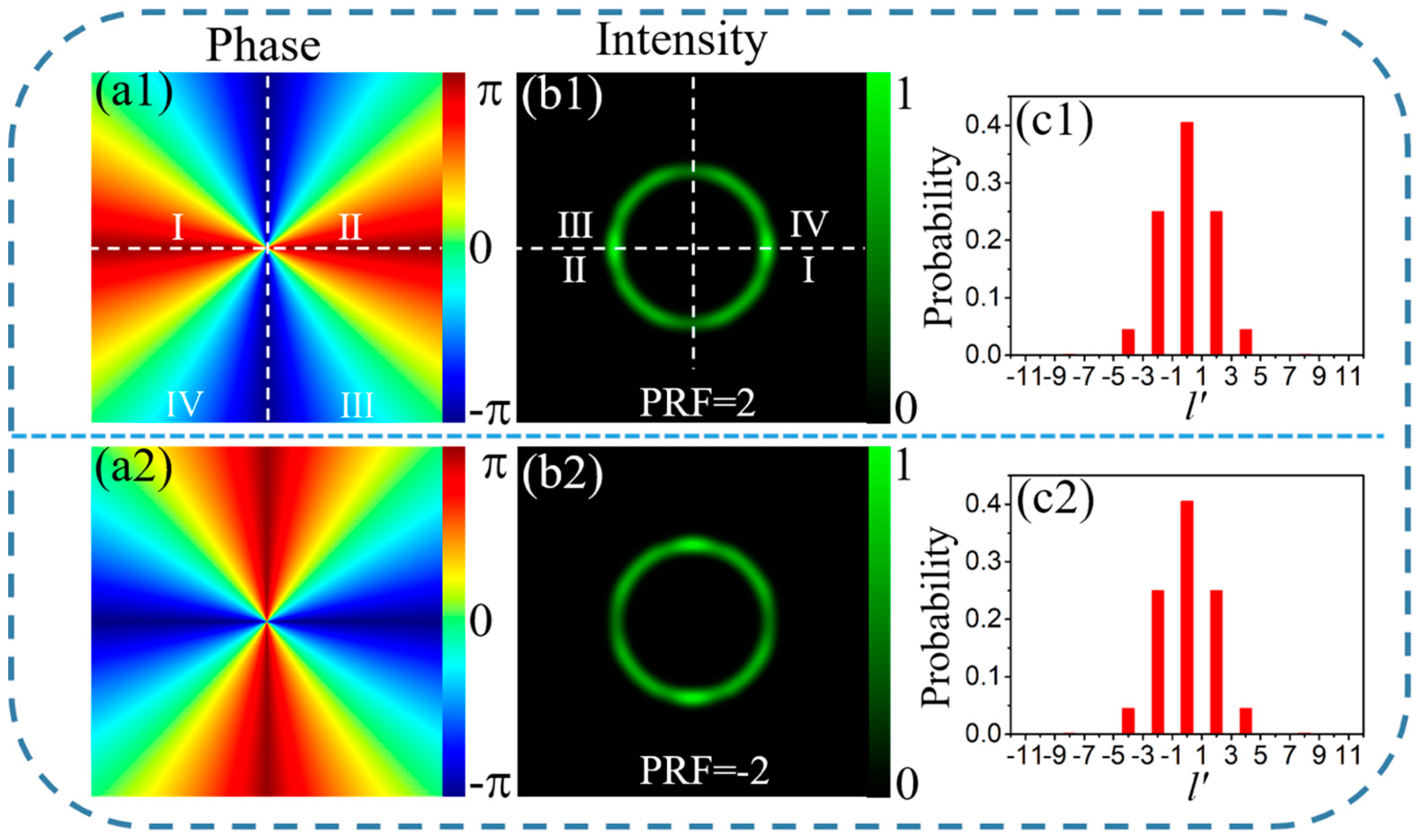
Firstly, we studied the generation process of the proposed CSOVs. To realize a centrosymmetric light field, the phase of the proposed CSOVs was combined with four local spiral phases of the conventional OVs with TC (l1 = −l2 = l3= −l4), where l1, l2, l3, l4 are the TC of the spiral phases located in the areas I, II, III, IV, respectively. For simply expressing the TC of the CSOV, we define a parameter, named as phase reconstruction factor (PRF), which possesses the relation PRF = l1 = −l2 = l3 = −l4. The parameter PRF is an integer, which is different from the average TC [(l1 + l2 + l3 + l4) / 4 ≡ 0]. As shown in Figure 1 (c1 and c2), the OAM states of the CSOVs are decomposed [23,24]. The OAM states of the CSOV are independent of the four TCs (l1, l2, l3, and l4) and a maximal probability distributed at the states of l’ = 0 which are due to the centrosymmetric OAM states. Moreover, for the conditions of PRF > 0 and PRF < 0, the light fields have the same profile and OAM states but orthogonality, shown in Figure 1. In addition, owing to the azimuthal energy flow distribution, the light field distributions revolve in far field which lead to interference in the local areas [25]. To realize a controllable interference area, we used an axicon to regulate the rotation angle of the OV in far field [26]. The CSOV can be defined by the following formula
where (ρ, θ) denotes the polar coordinates, k is the wave number, α and n are the cone angle and refractive index of the axicon, respectively. The rect(.) is the rectangular function which is used to realize the selecting and reconstructing of the four local spiral phases, and ln’ is the TC which determines the local OAM of the CSOV. Particularly, according to the definition of the TC [27,28], the TC of the CSOV given by L = l1 + l2 + l3 + l4 which is constant equal to 0.
3. Experimental Setup
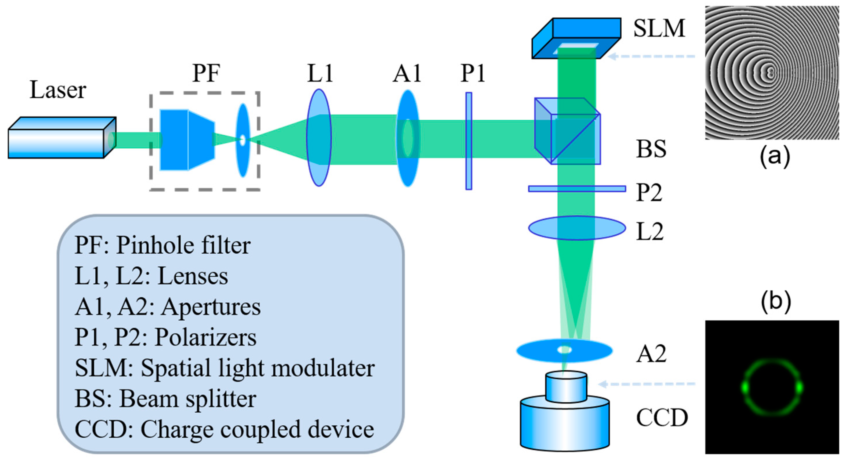
The schematic of the experimental setup is sketched in Figure 2. A reflective phase-only liquid-crystal spatial light modulator (SLM, HOLOEYE, Berlin, Germany PLUTO-VIS-016, pixel size: 8 μm × 8 μm) is illuminated with an approximate flat-top beam (wavelength 532 nm), modified by a pinhole filter and an aperture. Importantly, the polarizer P1 used before SLM is due to the SLM responding only for a horizontally polarized beam. Furthermore, the polarizer P2 used after SLM is to eliminate the unmodulated light. Then, the modulated beam realizes Fourier Transform by a lens (f = 200 mm) and is recorded by a CCD camera (Basler Ahrensburg Germany acA1600–60 gc, pixel size of 4.5 μm × 4.5 μm).
4. Results and Discussion
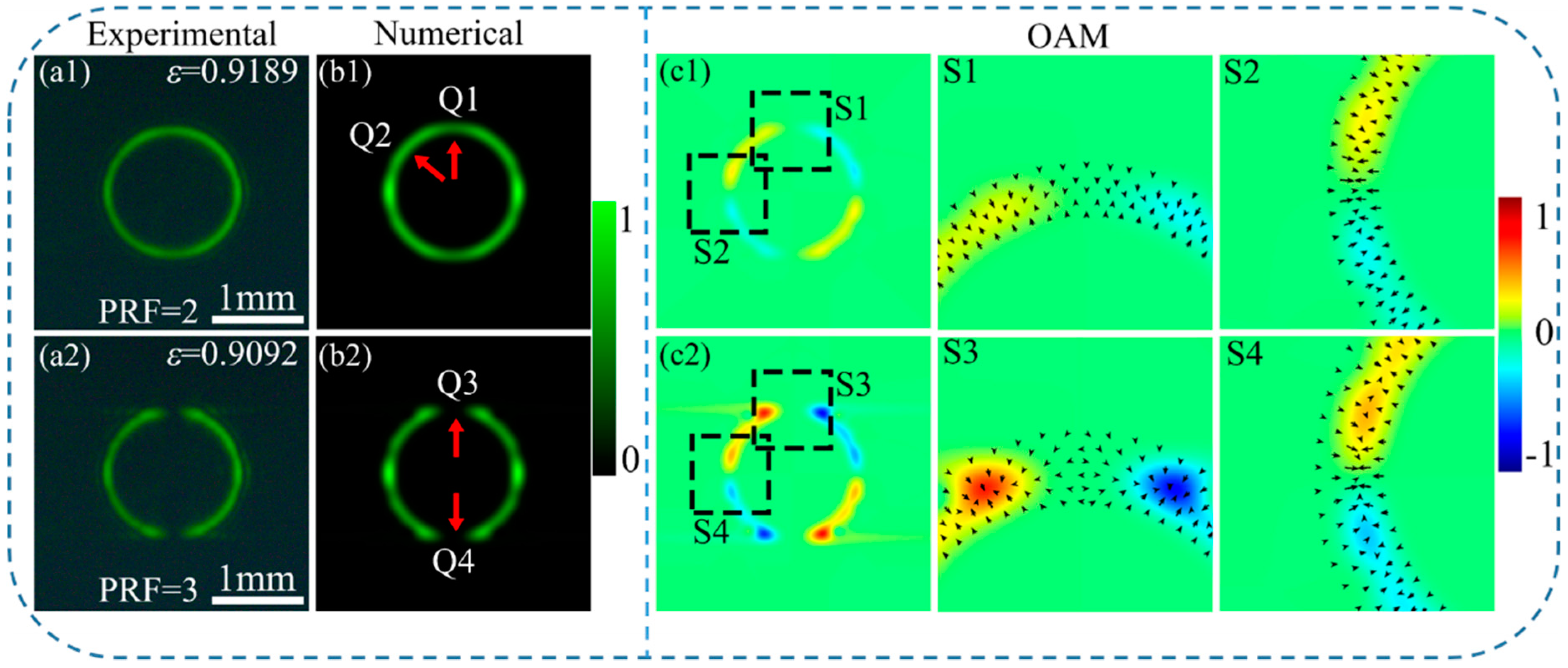
First, we will compare the properties of the CSOV’s intensity, OAM density, and gradient force between the PRF equaling to an odd and an even. The experimental intensity patterns and numerical simulation of the CSOVs (PRF = 2, 3) are displayed in the first and second columns of Figure 3, respectively. Their cone angle α of the axicon is 0.06. In the following studies, we mainly studied the properties of the left-half part which is similar to the right-half part due to the CSOV’s centrosymmetric light field. For PRF = 2, the local intensity at the joint Q1 is decreased. To characterize the magnitude of change, the intensity rate between the local extremun at Q1 and the uniform intensity position Q2 was calculated. The rate is greater than 65%, which is larger than 1/e of the uniform intensity at Q2. Therefore, the intensity at the joint Q1 can be considered as a smooth intensity distribution on the light ring. Furthermore, the intensity pattern of the CSOV (PRF = 3) has two gaps (Q3 and Q4) in the intensity ring due to the fractional phase jump at the joints, which is different to the CSOV (PRF = 2). However, two light petals formed in the left and right sides on the light ring of the CSOVs for PRF = 2 and PRF = 3, respectively. The reason is on account of the opposite azimuthal energy flow. As expected, the numerical simulation intensity patterns fit very well with the experimental results.
Furthermore, the mode purity ε is a significant parameter which can reveal the quality of the generated CSOVs. In our experiments, the mode purity was estimated via the correlation coefficients between the experimental intensity pattern and the numerical simulation intensity pattern [16,30]. As shown in Figure 3a1,a2, the values of the mode purity ε are both greater than 0.9, which indicates that the CSOVs still maintain a high beam quality.
Figure 3c1,c2 depict the centrosymmetric OAM distributions of the CSOV and the computing method refers to References [11,31]. For the local OAM density: Reds for positive values (counter-clockwise), blues for negative values (clockwise), and greens for zero. The OAM distribution in the left-half part of the OAM ring provides a pair of opposite twist forces. Meanwhile, the OAM distribution in the right-half part is centrosymmetric with the left half part. In order to display more details of the OAM density distributions, the 3 × magnification of the areas in the black boxes (S1–S4) in Figure 3c1,c2 are shown in Figure 3S1–S4, respectively. As Figure 3 shows, the OAM distributions in the area S1 are different from the area S3. The reason is the formation of the fractional phase jump when PRF is odd. Moreover, the twist forces provided by the OAM point to the center of the areas in S2 and S4, respectively. Furthermore, the arrows in Figure 3S1–S4 visualize the gradient force [32,33]. In the particle manipulation field, gradient force offers the trap force. As shown in Figure 3S2,S4, larger gradient force in the black dashed frames provides a larger trap force which can realize particle stability trapping. Hence, the OAM and the gradient force provide a motion tendency for particle towards the black dashed frames in micro-manipulation field.
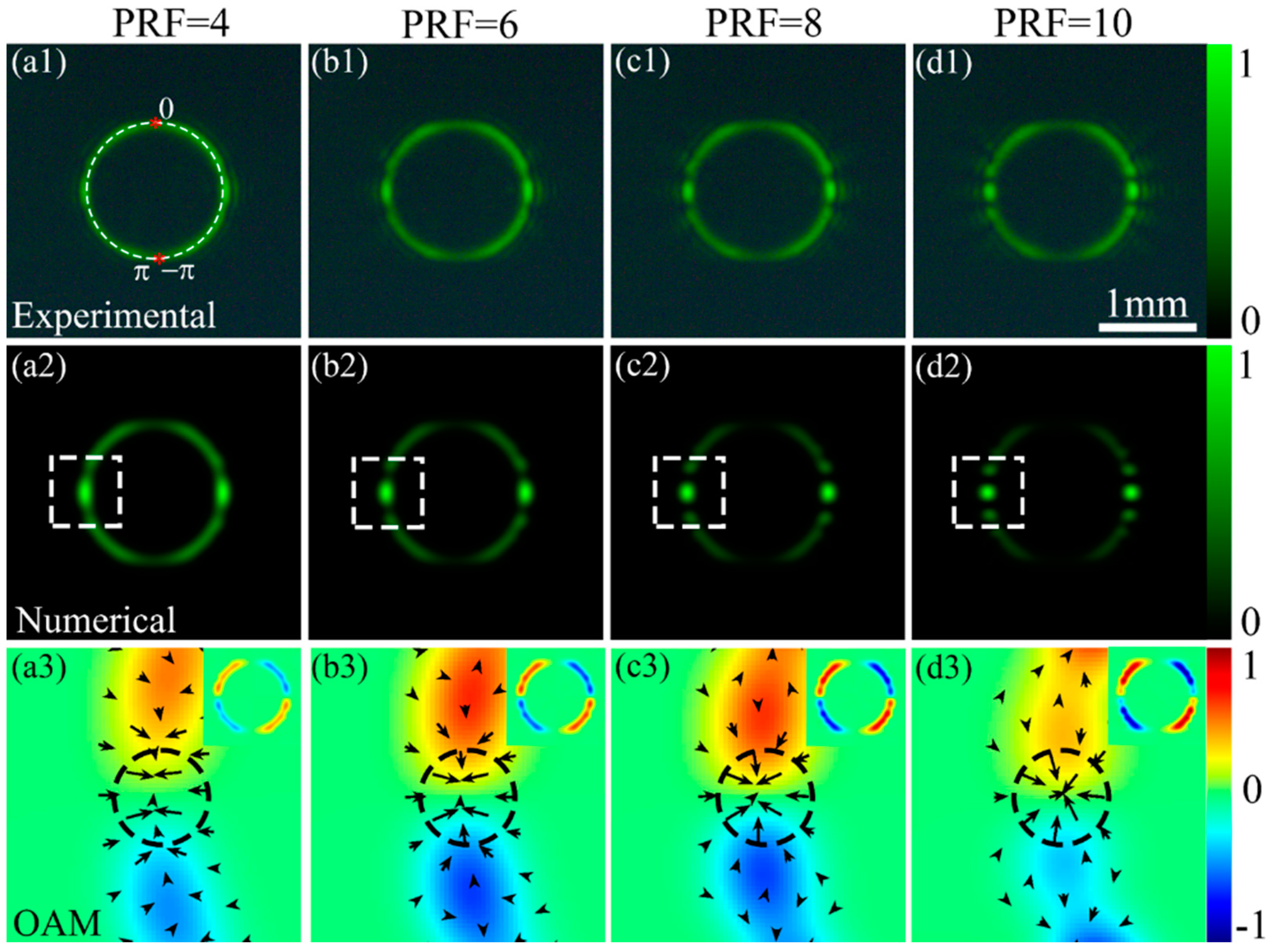
Let us study the modulation properties of the CSOV’s intensity, OAM distribution, and gradient force with the PRF increase from 2 to 10 in steps of 2. The first row of Figure 4 shows the experimental intensity patterns of the CSOV, and the second row displays the numerical simulation intensity patterns. For our experimental results, the number of the light petals increased with the increasing PRF, which is consistent with the numerical simulation intensity. The bottom row of Figure 4 depicts the OAM distribution with 4 × magnification of the areas in the white dashed frames in the second row of Figure 4, respectively. Furthermore, the whole OAM distributions of the CSOVs are shown in the subset of Figure 4a3–d3. With the increasing PRF, the magnitude of the local OAM of the areas in the white dashed frames are increased first and finally decreased. The reason is that the increasing PRF leads to the increase of the OAM’s magnitude. Meanwhile, as the interference area increases, the positive and negative local OAM cancel each other out [26]. Moreover, the increasing gradient force of the black circle dashed frames in Figure 4a3–d3 indicates that the CSOV can provide stronger trapping force with a larger PRF.
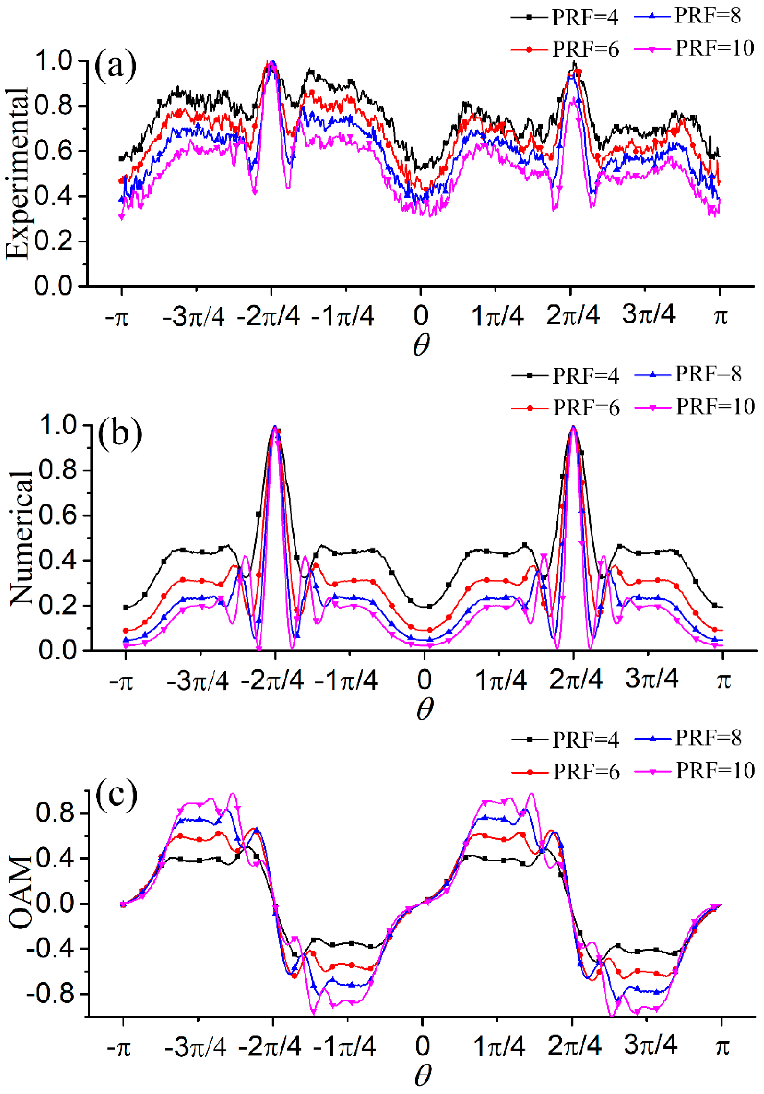
To study the properties of the CSOV, the center profiles of the CSOV’s intensity and OAM rings in Figure 4 are plotted in Figure 5. For the intensity distributions, two peaks form at θ= ± π/2 due to the generation of petals in the interference area, which ensures a larger gradient force to form an optical trap. Meanwhile, the OAM decreases to zero at the intensity peak positions. For the local OAM distribution profiles located in the non-interference area, the magnitude of the OAM increases with the increasing PRF, which reflects that the local OAM maintains the properties of the spiral phases used in the initial field.
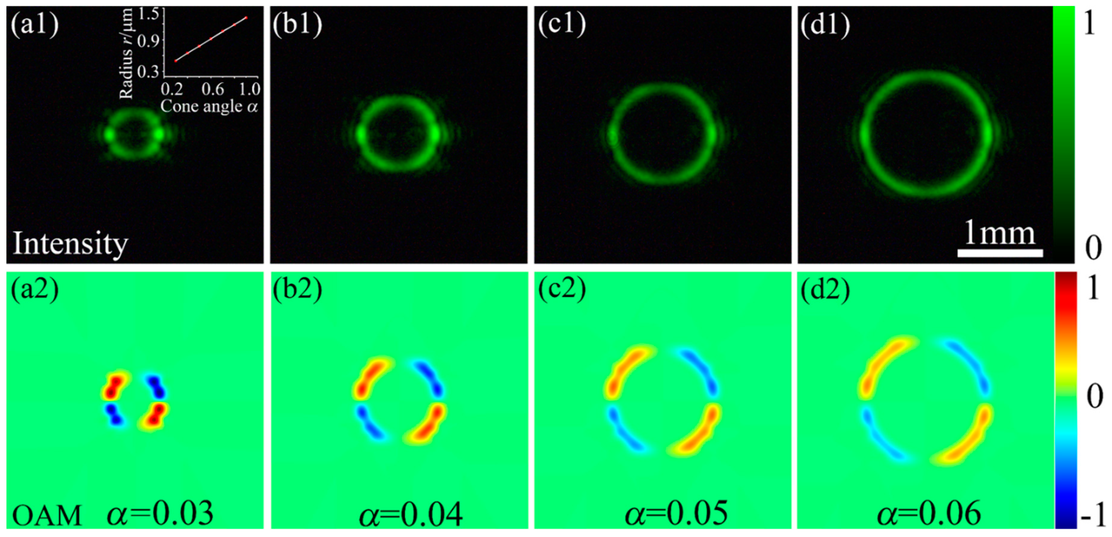
To enhance the regulatory flexibility of the CSOV, the cone angle of the axicon is used as an adjustable parameter to modulate the radius. The intensity and OAM distributions of the CSOVs (PRF = 4) with different cone angles α are shown in Figure 6. One can find that the radius of the CSOV increases with the cone angle increasing. To quantitatively represent the relationship between the radius and the cone angle, we fitted the experimental dates, as shown in Figure 6a1. Their relationship is accord with the linear equation, r = 0.0985 + 1.36α, and the correlation coefficient is 0.99977. Furthermore, the magnitude of the OAM density decreases due to the constant total OAM. Owing to the optical trap formed in the interference areas demonstrated in the above, the regulation property of the cone angle α indicates the potential significance in the separating cells.
5. Conclusions
We have proposed a centrosymmetric optical vortex (CSOV), in which the phases consist of four spiral phases of conventional OVs with TC (l1 = −l2 = l3 = −l4). All of the intensity, phase, and OAM distributions are centrosymmetric. The analysis of the OAM and the gradient force indicates that the joints of the CSOV in the left and right sides form two optical traps due to the interference. Moreover, the interference areas and the magnitude of the OAM can be modified by a single parameter PRF. The distance between the left and right optical traps are regulated via the control of the radius of the CSOV by using the cone angle parameter. This work provides a novel detached asymmetric light field, which can potentially be used in macro-particle manipulation—especially separating cells.
Author Contributions
Data curation, H.Z.; formal analysis, H.M.; methodology, H.Z.; project administration, X.L. and Y.C.; supervision, X.L., M.T., H.L., and Y.C.; writing—original draft, H.Z.; writing—review and editing, X.L., H.M., M.T., H.L., and Y.C.
Funding
This research was funded by the National Natural Science Foundation of China [grant numbers 61775052, 11704098, 11525418, and 91750201].
Conflicts of Interest
The authors declare no conflict of interest.
References
- Grier, D.G. A revolution in optical manipulation. Nature 2003, 424, 810. [Google Scholar] [CrossRef] [PubMed]
- Dholakia, K.; Čižmár, T. Shaping the future of manipulation. Nat. Photonics 2011, 5, 335. [Google Scholar] [CrossRef]
- Chen, M.; Mazilu, M.; Arita, Y.; Wright, E.M.; Dholakia, K. Dynamics of microparticles trapped in a perfect vortex beam. Opt. Lett. 2013, 38, 4919–4922. [Google Scholar] [CrossRef] [PubMed]
- Wang, J.; Yang, J.; Fazal, I.M.; Ahmed, N.; Yan, Y.; Huang, H.; Ren, Y.; Yue, Y.; Dolinar, S.; Tur, M.; et al. Terabit free-space data transmission employing orbital angular momentum multiplexing. Nat. Photonics 2012, 6, 488. [Google Scholar] [CrossRef]
- Bozinovic, N.; Yue, Y.; Ren, Y.; Tur, M.; Kristensen, P.; Huang, H.; Willner, A.E.; Ramachandran, S. Terabit-scale orbital angular momentum mode division multiplexing in fibers. Science 2013, 340, 1545–1548. [Google Scholar] [CrossRef]
- Willner, A.E.; Huang, H.; Yan, Y.; Ren, Y.; Ahmed, N.; Xie, G.; Bao, C.; Li, L.; Cao, Y.; Zhao, Z.; et al. Optical communications using orbital angular momentum beams. Adv. Opt. Photonics 2015, 7, 66–106. [Google Scholar] [CrossRef]
- Zhu, X.; Wang, K.; Wang, F.; Zhao, C.; Cai, Y. Coupling efficiency of a partially coherent radially polarized vortex beam into a single-mode fiber. Appl. Sci. 2018, 8, 1313. [Google Scholar] [CrossRef]
- Lavery, M.P.J.; Speirits, F.C.; Barnett, S.M.; Padgett, M.J. Detection of a spinning object using light’s orbital angular momentum. Science 2013, 341, 537. [Google Scholar] [CrossRef] [PubMed]
- Ma, H.; Li, X.; Tai, Y.; Li, H.; Wang, J.; Tang, M.; Wang, Y.; Tang, J.; Nie, Z. In situ measurement of the topological charge of a perfect vortex using the phase shift method. Opt. Lett. 2017, 42, 135–138. [Google Scholar] [CrossRef]
- Aleksanyan, A.; Kravets, N.; Brasselet, E. Multiple-star system adaptive vortex coronagraphy using a liquid crystal light valve. Phys. Rev. Lett. 2017, 118, 203902. [Google Scholar] [CrossRef] [PubMed]
- Allen, L.; Beijersbergen, M.W.; Spreeuw, R.J.C.; Woerdman, J.P. Orbital angular momentum of light and the transformation of Laguerre-Gaussian laser modes. Phys. Rev. A 1992, 45, 8185–8189. [Google Scholar] [CrossRef] [PubMed]
- Kotlyar, V.V.; Kovalev, A.A.; Soifer, V.A. Asymmetric Bessel modes. Opt. Lett. 2014, 39, 2395–2398. [Google Scholar] [CrossRef]
- Kovalev, A.A.; Kotlyar, V.V.; Porfirev, A.P. Optical trapping and moving of microparticles by using asymmetrical Laguerre-Gaussian beams. Opt. Lett. 2016, 41, 2426–2429. [Google Scholar] [CrossRef] [PubMed]
- Kotlyar, V.V.; Kovalev, A.A.; Porfirev, A.P. Asymmetric Gaussian optical vortex. Opt. Lett. 2017, 42, 139–142. [Google Scholar] [CrossRef] [PubMed]
- Kovalev, A.A.; Kotlyar, V.V.; Porfirev, A.P. A highly efficient element for generating elliptic perfect optical vortices. Appl. Phys. Lett. 2017, 110, 5. [Google Scholar] [CrossRef]
- Li, X.; Ma, H.; Yin, C.; Tang, J.; Li, H.; Tang, M.; Wang, J.; Tai, Y.; Li, X.; Wang, Y. Controllable mode transformation in perfect optical vortices. Opt. Express 2018, 26, 651–662. [Google Scholar] [CrossRef] [PubMed]
- Li, P.; Liu, S.; Peng, T.; Xie, G.; Gan, X.; Zhao, J. Spiral autofocusing Airy beams carrying power-exponent-phase vortices. Opt. Express 2014, 22, 7598–7606. [Google Scholar] [CrossRef]
- Ma, H.; Li, X.; Zhang, H.; Tang, J.; Li, H.; Tang, M.; Wang, J.; Cai, Y. Optical vortex shaping via a phase jump factor. Opt. Lett. 2019, 44, 1379–1382. [Google Scholar] [CrossRef]
- Abramochkin, E.G.; Volostnikov, V.G. Spiral light beams. Phys. Usp. 2004, 47, 1177–1203. [Google Scholar] [CrossRef]
- Rodrigo, J.A.; Alieva, T.; Abramochkin, E.; Castro, I. Shaping of light beams along curves in three dimensions. Opt. Express 2013, 21, 20544–20555. [Google Scholar] [CrossRef]
- Rodrigo, J.A.; Alieva, T. Freestyle 3D laser traps: Tools for studying light-driven particle dynamics and beyond. Optica 2015, 2, 812–815. [Google Scholar] [CrossRef]
- Bezryadina, A.S.; Preece, D.C.; Chen, J.; Chen, Z. Optical disassembly of cellular clusters by tunable ‘tug-of-war’ tweezers. Light-Sci. Appl. 2016, 5, e16158. [Google Scholar] [CrossRef]
- Frankearnold, S. Quantum formulation of fractional orbital angular momentum. J. Mod. Opt. 2007, 54, 1723–1738. [Google Scholar]
- Tkachenko, G.; Chen, M.; Dholakia, K.; Mazilu, M. Is it possible to create a perfect fractional vortex beam? Optica 2017, 4, 330–333. [Google Scholar] [CrossRef]
- Arlt, J. Handedness and azimuthal energy flow of optical vortex beams. J. Mod. Opt. 2003, 50, 1573–1580. [Google Scholar] [CrossRef]
- Li, X.; Ma, H.; Zhang, H.; Tang, M.; Li, H.; Tang, J.; Wang, Y. Is it possible to enlarge the trapping range of optical tweezers via a single beam? Appl. Phys. Lett. 2019, 114, 081903. [Google Scholar] [CrossRef]
- Nye, J.F.; Berry, M.V. Dislocations in wave trains. Proc. R. Soc. Lond. A-Math. Phys. Eng. Sci. 1974, 336, 165–190. [Google Scholar] [CrossRef]
- Gbur, G. Fractional vortex Hilbert’s Hotel. Optica 2016, 3, 222–225. [Google Scholar] [CrossRef]
- Vaity, P.; Rusch, L. Perfect vortex beam: Fourier transformation of a Bessel beam. Opt. Lett. 2015, 40, 597–600. [Google Scholar] [CrossRef]
- Ohtake, Y.; Ando, T.; Fukuchi, N.; Matsumoto, N.; Ito, H.; Hara, T. Universal generation of higher-order multiringed Laguerre-Gaussian beams by using a spatial light modulator. Opt. Lett. 2007, 32, 1411–1413. [Google Scholar] [CrossRef]
- O’Neil, A.T.; MacVicar, I.; Allen, L.; Padgett, M.J. Intrinsic and extrinsic nature of the orbital angular momentum of a light beam. Phys. Rev. Lett. 2002, 88, 053601. [Google Scholar] [CrossRef]
- Ashkin, A.; Dziedzic, J.M.; Bjorkholm, J.E.; Chu, S. Observation of a single-beam gradient force optical trap for dielectric particles. Opt. Lett. 1986, 11, 288–290. [Google Scholar] [CrossRef]
- Zhang, Y.; Xue, Y.; Zhu, Z.; Rui, G.; Cui, Y.; Gu, B. Theoretical investigation on asymmetrical spinning and orbiting motions of particles in a tightly focused power-exponent azimuthal-variant vector field. Opt. Express 2018, 26, 4318–4329. [Google Scholar] [CrossRef]
Figure 1.
Schematic of the centrosymmetric optical vortex (CSOV) generation. (a1,a2) are spiral phase patterns, (b1,b2) are intensity patterns, and (c1,c2) are decompositions of the orbital angular momentum (OAM) states, where l’∈(-∞, ∞) is an integer reflected the single states.
Figure 1.
Schematic of the centrosymmetric optical vortex (CSOV) generation. (a1,a2) are spiral phase patterns, (b1,b2) are intensity patterns, and (c1,c2) are decompositions of the orbital angular momentum (OAM) states, where l’∈(-∞, ∞) is an integer reflected the single states.

Figure 2.
Schematic of the experimental setup. (a) phase mask written into the spatial light modulator (SLM) and (b) the intensity record by the CCD camera.
Figure 2.
Schematic of the experimental setup. (a) phase mask written into the spatial light modulator (SLM) and (b) the intensity record by the CCD camera.

Figure 3.
Comparison of CSOVs with phase reconstruction factor (PRF) equaling to an odd and an even, respectively. (a1,a2) are experimental intensity, (b1,b2) are numerical simulation intensity. (c1,c2) and (S1–S4) are the numerical simulation OAM distribution. In the fourth and fifth columns, the arrows visualize the gradient force. The ε values represent the mode purity of the generated CSOVs. The joints in the intensity rings mean that the border lines between quadrants in Figure 1a1,a2.

Figure 4.
Distributions of the intensity and OAM density of the CSOVs with the PRF = 4, 6, 8, 10, respectively. (a1–d1) are experimental intensity, (a2–d2) are numerical simulation intensity, and (a3–d3) are OAM density distribution.
Figure 4.
Distributions of the intensity and OAM density of the CSOVs with the PRF = 4, 6, 8, 10, respectively. (a1–d1) are experimental intensity, (a2–d2) are numerical simulation intensity, and (a3–d3) are OAM density distribution.

Figure 5.
(a–c) are the center profiles of the CSOV’s experimental intensity, numerical simulation intensity and OAM rings of Figure 4, respectively. For instance, the positions of the date ring and the three points 0, −π and π are shown in Figure 4a1.

Figure 6.
Intensity and OAM distributions of CSOV (PRF = 4), with different radius by changing the cone angle of the axicon. (a1–d1) are experimental intensity and (a2–d2) are numerical simulation OAM distributions.
Figure 6.
Intensity and OAM distributions of CSOV (PRF = 4), with different radius by changing the cone angle of the axicon. (a1–d1) are experimental intensity and (a2–d2) are numerical simulation OAM distributions.

© 2019 by the authors. Licensee MDPI, Basel, Switzerland. This article is an open access article distributed under the terms and conditions of the Creative Commons Attribution (CC BY) license (http://creativecommons.org/licenses/by/4.0/).
Share and Cite
MDPI and ACS Style
Zhang, H.; Li, X.; Ma, H.; Tang, M.; Li, H.; Cai, Y. Centrosymmetric Optical Vortex. Appl. Sci. 2019, 9, 1429. https://0-doi-org.brum.beds.ac.uk/10.3390/app9071429
AMA Style
Zhang H, Li X, Ma H, Tang M, Li H, Cai Y. Centrosymmetric Optical Vortex. Applied Sciences. 2019; 9(7):1429. https://0-doi-org.brum.beds.ac.uk/10.3390/app9071429
Chicago/Turabian StyleZhang, Hao, Xinzhong Li, Haixiang Ma, Miaomiao Tang, Hehe Li, and Yangjian Cai. 2019. "Centrosymmetric Optical Vortex" Applied Sciences 9, no. 7: 1429. https://0-doi-org.brum.beds.ac.uk/10.3390/app9071429
Note that from the first issue of 2016, this journal uses article numbers instead of page numbers. See further details here.