Review

Influence of Different Static Equilibrium Calculation Methods on the Dynamic Response of Marine Cables during the Releasing Process: Review and a Case Study

1
Ship and Maritime College, Guangdong Ocean University, Zhanjiang 524088, China
2
Ocean College, Zhejiang University, Zhoushan 316000, China
3
Faculty of Maritime and Transportation, Ningbo University, Ningbo 315211, China
4
School of Electronics and Information Engineering, Guangdong Ocean University, Zhanjiang 316021, China
*
Author to whom correspondence should be addressed.
J. Mar. Sci. Eng. 2023, 11(4), 764; https://0-doi-org.brum.beds.ac.uk/10.3390/jmse11040764
Submission received: 3 March 2023 / Revised: 28 March 2023 / Accepted: 29 March 2023 / Published: 31 March 2023
(This article belongs to the Special Issue Young Researchers in Ocean Engineering)

Abstract

:
When analyzing the dynamic characteristics of marine cables, the static equilibrium state must first be calculated; a dynamic analysis can then be carried out based on the static equilibrium. Since the calculation of the static equilibrium is the basis of dynamic calculation, different methods for the calculation of the static equilibrium will have important impacts on the dynamic response characteristics of cables, which result in cables having different dynamic characteristics. This paper summarizes the research progress in the effects of different methods for the calculation of the static equilibrium on the dynamic response of marine cables during the releasing process, and current methods for their static calculation are more comprehensively developed as well as being more accurate. To study the influence of different static equilibrium calculation methods, with the reference of some specific parameters of a mooring cable, combined with specific sea conditions, through the necessary simplification of the cable releasing process, based on the lumped mass method, mooring cables are discretized into the lumped mass model, and dynamic analysis models of the releasing process of mooring cables under three methods for the calculation of the static equilibriums (the fast static equilibrium calculation method, the analytic catenary calculation method, and the catenary calculation method) are established. The dynamic characteristics of the spatial configurations of mooring cables based on different static equilibrium calculation methods are obtained through time domain coupling analyses. It was found that if the static equilibrium of a cable is calculated, taking into account gravity, buoyancy, wave current resistance, inertia forces, and the axial stiffness of a cable, then the characteristics of a cable during dynamic descent are closest to that of a real situation. The calculation results have a certain guiding significance for specific engineering practices.

1. Review of Calculation Methods

Marine composite mooring and towing lines are usually composed of lines, chains, buoys, and underwater objects; they are subject to wave, current, and other interactions. The calculation of a marine cable is divided into two parts: a static analysis and a dynamic analysis, where the static analysis is the basis for the dynamic analysis and the results are used as the initial conditions for the dynamic analysis [1,2,3], so it is necessary to predict their static configuration under different conditions from the early stage of the design process. Section 1.1. introduces the static equilibrium calculation of a marine cable and describes the different methods currently used for a static analysis. Section 1.2. introduces the current methods for and research progress in the calculation of the dynamic response of a marine cable.

1.1. Static Equilibrium Calculation of a Marine Cable

The analysis of and research on the performance of traction/mooring systems began at the beginning of the 20th century. At the beginning, Macleod performed a two-dimensional analysis of a traction cable in 1918. In 1957, Zajac, E.E., carried out a study on a three-dimensional analysis of a balanced configuration of suspended telephone cable applications [4]. In 1980, Nakajima et al. [5] developed a new method based on a lumped mass model that can be used for the complete analyses (both static and dynamic) of cable mechanics.
So far, various methods (the lumped mass model, the quasistatic model, the finite element model, etc.) have been used in mooring line modeling [6]. In order to fully analyze cable movement, the initial configuration of a cable must be determined, which is considered as a balanced configuration, as shown in Figure 1. The model is composed of the differential equations of the static equilibrium configuration [7].
The solutions can be obtained in two different cases: The first is where the boundary conditions are imposed at both ends of the line; only a part of the configuration parameters is known, and the remaining parameters are determined through computation. The second is where the boundary conditions are imposed only at one of the line ends. All of the parameters must be known at the cable end where the computation begins. The conditions that are required for stopping the computation are imposed at the other line end.
Researchers have come to recognize the importance of gravity, buoyancy, shear forces, and the axial elasticity of a cable in the static analysis of a marine cable. When the flow velocity is low, the influence of friction can be ignored. This is not the case for most traction systems. For these traction systems, the coefficient of friction is usually determined by experiments through hydrodynamic or aerodynamic tests on a sample cable. According to Pode’s test data [8], the tangential component of hydrodynamic force acting on circular and stranded cables was significantly smaller than the normal component, except that the cable and water flow were inclined at a very small angle. In addition, if a cable was too short and the tension change in a cable’s length was small relative to the force at the end of a cable, ignoring the tangential component of fluid dynamics was permitted [7]. S. Chucheepsakul et al. [9] presented a method for the static analysis of a marine cable spanning two fixed points. The top tension of the cable was given, while the total arc length, equilibrium configuration, and top as well as bottom angles were determined. In the analysis, a function was introduced in which the potential energy of stretching and virtual work carried out by other forces were included the stationary condition of the function; one of two equilibrium equations were used to solve the problem. Although the governing differential equations of a cable segment are simple, explicit solutions can only be obtained for simple cases due to the nonlinearity [10,11]. Jun Zhanga et al. [12] used the lumped mass method to build a two-dimensional model and investigated the structure as well as tension distribution of various mooring lines under the combined action of currents and waves in a quasistatic analysis. The analysis results showed that the pretension, velocity, and shear strength had a significant impact on the tension distribution and configuration of mooring lines. Pankaj Kumar et al. [13] proposed a new dynamic model of catenary mooring lines based on the vector form eigen finite element (VFFE) method. The purpose of this method was to calculate the motion of the system, which might include large rigid body motion, large geometric changes, or very large deformation. Inertia, hydrodynamics, and seafloor interactions are included in the model.
In most analyses, the effect of axial deformation on the equilibrium configuration is ignored; however, if the axial flexibility of a cable is large, the results of ignoring axial deformation need to be carefully checked [14]. Huang et al. [15] proposed a formula with which to obtain the cable balance configuration considering the effect of axial deformation. For cases involving small axial strain, the solution was reasonable for engineering applications. Thomas U. Watson et al. [16] proposed a simulation model which was consistent with large underwater instrumented structures constructed of extensible cables subject to arbitrary current profiles. Recent activities in the offshore oil extraction industry require the adoption of new structural concepts for flexible pipelines (mooring lines and risers) [17,18]. This kind of system presents more and more complex configurations in addition to having dynamic nonlinear behavior; therefore, the use of an efficient numerical solution program based on the finite element method becomes a mandatory requirement for its analysis [19].
A number of researchers have since carried out static calculations of cables by improving the finite element method. The conventional finite element method (FEM) analysis program for flexible lines is based on the calculation of the initial stable static equilibrium configuration to define the finite element mesh. This configuration is usually obtained through the classical catenary equation [20,21]. G. Moe et al. [22] developed an analytical expression for the shape of steel catenary risers (SCRs) under the influence of its dead weight, assuming that it was at least evenly segmented along the riser axis. The closed-form expressions of riser tension and related axial elongation would also be given. Finally, an approximate but quite accurate solution for SCR bending moment distribution and its influence on displacement would be given. Chainarong Athisakul et al. [23] proposed a finite element method with which to calculate the static equilibrium configuration and applied top tension of an expandable marine riser under the specified total arc length. Based on the functional principle, the variational formula of an expandable marine riser was formulated. The variational model formula involves the strain energy caused by bending and axial tension, as well as the virtual work completed by hydrostatic pressure and other external forces. Marco Lepidi et al. [24] developed an elastic continuous one-dimensional model for damaged cables (including geometric nonlinearity). Damage was described as a diffuse reduction in the axial stiffness of a cable and is defined by its strength, range, and location. The exact solution of the static balance equation of a cable under the dead weight was obtained, and the significance of the tension loss and sag increase caused by the damage was studied under the actual significant parameter changes. Gang Ma et al. [25] established a nonlinear mechanical model that could be used to deal with large deformation problems with global slope as the unit coordinate, rather than the rotation used in the traditional finite element model.
In order to more accurately calculate the static equilibrium results of a marine cable, many researchers have started to consider the effects of gravity, buoyancy, wave and current resistance, inertia, and the axial stiffness of the cable on gravity, buoyancy, wave and current resistance, inertia, and the axial stiffness of the cable. The balance equation is established in the deformation configuration. With the help of global coordinates, the nonlinear relationship between the strain and displacement can be easily described. Yang et al. [26] developed numerical programs for static and dynamic nonlinear analyses of mooring lines. Based on the total Lagrange formula, a geometrically nonlinear finite element method using two-point iso-parametric cable elements was obtained, and then the static and dynamic equilibrium equations of mooring lines were established. The incremental iteration method was used to determine the initial static equilibrium state of a cable system under the action of dead weight, buoyancy, and water flow. Traditionally, researchers use numerical methods to solve unknown responses at the boundary nodes, and the solution is sensitive to the initial guess. The proposed semi-analytic solution avoids this difficulty [27]. Anil Kumar Sharma et al. [28] proposed a semi-analytical solution for the static equilibrium analysis of non-extensible cables to understand their initial configuration and tension. The obtained results were verified by the numerical solution of static section and cable tension. In addition, the mooring analysis program (MAP) is an open source project being developed by the National Renewable Energy Laboratory (NREL) to support the modeling of floating offshore wind turbines, wave energy converters, ocean current turbines, and related research topics. The quasistatic model used in the MAP was derived from a set of closed-form analytical solutions of a continuous cable with homogeneous properties [29]. Such models account for the effects of distributed cable mass, strain, and cable elasticity to provide the line profile and effective forces for a cable suspended at a steady state (static equilibrium). Forces arising from inertia, viscous drag, internal damping, bending, and torsion are neglected [30]. Based on the nonlinear finite element formula, Wan et al. [31] proposed a method with which to determine the equilibrium configuration and tension of a submerged rope system in uniform flow. The standard straight rope element was used to simulate the rope segment of the system. The formula includes rope stretching and introduces a hydrodynamic model for the rope. When the method is applied to the long line model, good compatibility between the numerical simulation and the experimental behavior is shown. In applying the displacement-based finite element method to the static structural analysis of complex catenary mooring systems, a lack of bending and compressional stiffness leads to the ill conditioning of the tangent stiffness matrix. Shukai Wu et al. [32] developed a new adaptive dynamic relaxation algorithm and solved the dynamic motion equation by using the Newmark integral formula. The detailed adaptive control program of time step, load step, damping level, and integral parameters were given. Russell J. Smith et al. [33] solved the catenary equation of a three-component mooring system consisting of two lines connected to a point buoy or sinker with a given water depth and fairlead tension. The problem was transformed into an octave polynomial equation and solved via Laguerre’s iteration. In the absence of buoys or sinkers, the equation was simplified to a quadratic equation, which could be solved in closed form. The elongation of the line has been proven to be equivalent to a small uncertainty of the weight per unit of length. This method has high computational efficiency.
As of now, the static analysis methods for marine cables have become more comprehensive and accurate, increasingly taking into account the effects of gravity, buoyancy, wave resistance, inertial forces, and the axial stiffness of a cable to ensure the accuracy of a cable’s characteristics during dynamic descent.

1.2. Solution of Marine Cables

Marine cables are supple flexural elements that are commonly employed in marine resource exploration and development. It is a common occurrence that, during the operation of the mooring cable in position, the top of the mooring fails to function due to poor marine conditions or excessive external loading and sinks to the bottom.
The lumped mass model was utilized by Zhu and Wan. They proposed a new element reference frame based on the orientation vectors of an element and a fluid’s relative position. This frame addressed situations in which the Freret frame and Euler angle generate structural polarities [34]. Huan, Xing et al. [35] proposed a mathematical model and numerical simulation for laying marine cables along a prescribed trajectory on the seabed by using a brand new mathematical approach, Augustus et al. [36] discretized a long cable into several segments and averaged the equivalent distributed dampings based on the energy dissipated during one cycle. The mathematical formulations were based on non-dimensional parameters. A comparison was made between the proposed model and the Classification Society’s recommended practice formulation, as well as non-dimensional parametric studies. Through the collaboration of Zhang, Bai, and Zhu from Zhejiang University with Zhu and Zhang from Ningbo University, an umbilical cable dynamic model was developed. This model was developed to study the dynamics of umbilical cords under specific interference conditions. Based on the simulation results, different factors affect interference occurrence, including the depth of the sea, the direction of the waves, and pipeline length; as the umbilical cable as well as riser depth and size increase, the channel flexibility will change; and as the wave direction changes, the motion boundary and collision form of the system changes [37]. Using the Galerkin method, Huang examined small sagging marine cables operating in alternating taut and slack conditions. According to the study, it was only necessary to consider the symmetric modes associated with the mid-span [38]. A variational model formulation was proposed by Chucheepsakul et al. [39] for analyzing the three-dimensional steady-state behavior of an extensible marine cable. It is formulated to incorporate virtual strain energy due to cable stretching, as well as virtual work performed by gravitational, inertial, and external drag forces. Zhu [40] presented the fact that a new nodal position finite element method could be applied to effectively simulate the dynamics of cable systems involving large rigid body rotations coupled with small elastic deformations.
A marine tethered remotely operated vehicle system with large elastic deformations and snap loads were studied by Zhu et al. [41] using the lumped parameter model. A linearization iteration scheme was developed by Xu and Wang [42]. A scheme for making an FSM-based dynamics calculation was time-saving and stable, making it suitable for predicting the shape of free-hanging marine risers or for controlling them in real time. In a rotary bending test rig, Witz and Tan [43,44] presented a stress analysis of a marine cable or umbilical. A mathematical model was also presented to predict the structural behavior of flexible pipes, umbilicals, and marine cables under axial–torsional loads. Wang et al. [45] proposed an algorithm for dealing with discrete governing equations that are aimed at the discrete mathematical model of a towing cable. According to the simulation results, the length change complicated the movement of the cable. During the start and end stages of deployment and recovery, cable tension fluctuated severely. A numerical simulation was used to examine the influence of tugboat motion in waves on the unfolding and recovery of cables. An analysis of the three-dimensional (3D) behavior of marine cables and segmented elastic mooring line catenaries used for floating offshore structures was presented by Vaz and Patel [46]. The formulation and solution of the governing equations were presented. The response of segmented elastic mooring line catenaries was investigated when subjected to arbitrary sheared currents.
A numerical and experimental investigation of the dynamic behavior of a towed low-tension cable applicable to a towed array sonar system for submarine detection was conducted by Park et al. [47]. The results showed that an effective agreement was only possible when vibrations initiated by vortices resulted in increased drag coefficients. For numerical modeling, non-uniform element lengths are also necessary to account for the sharp variation in tension and shear forces near the top fixed end. An experimental and numerical study conducted by Niedzwecki and Sreekumar [48] investigated the dynamic behavior of a towed low-tension cable applicable to the detection of submarines using a towed array sonar system. In experiments and numerical simulations, Triantafyllou and Mavrakos [49] also studied the dynamics of mooring lines for deep water applications with submerged buoys attached to them at the Massachusetts Institute of Technology and the National Technical University of Athens, respectively. Kurniawan and Mira [50] conducted a technical study on ocean current power plants. They developed a method for determining the cable length, dimensions of the pipe protector, stability analysis, and cable-laying analysis for a subsea cable system. Based on a single-degree-of-freedom model, Huang [51] examined the dynamic stability of the heave motion of marine cable-body systems operating in taut and slack conditions. Through period doubling, numerical simulations also demonstrated the transition from a periodic to a chaotic response. Huang [52], from the University of Strathclyde, presented a numerical method for predicting the dynamic behavior of marine cables in three dimensions. In order to demonstrate the validity of the approach, a numerical example is provided. A semi-analytic approach was presented by Huang and Vassalos to predict the static performance of marine cables. The validity of the approach was demonstrated by several numerical examples. Ghaddimi et al. [53] used the lumped mass discretization method to derive equations of motion for flexible risers in three dimensions. Fluid loading on the structure was calculated using the Morison equation, which included nodal shear forces and bending moments. Based on a comparison of the results with experimental values, analytical solutions, and independent publications, it appeared that the results were in good agreement. Peltzer et al. [54] presented wind tunnel experiments that examined the effects of forced synchronized vibrations and a helically wound cross-section of a cable on near-wake vortex shedding parameters. It was found that the range of flow speeds over which vortex shedding was locked to the vibration frequency varied directly with vibration amplitude. As a result of the helical cross section and the synchronized vibration, significant changes in the near-wake development were observed, which were directly related to the increased hydrodynamic forces associated with unforced synchronized vibrations. Chen et al. [55] presented a numerical study on the dynamics of marine cables that were widely used in the offshore industry.
The use of a multiscale full waveform inversion (FWI) was proposed by Bian et al. [56] in order to improve the illumination coverage of vertical cable surveys. A multiscale FWI is an effective model-building tool in deep-water exploration, according to synthetic results. A study conducted by Beasley [57] demonstrated that the acquisition of slanted cables was necessary for wave equation de-ghosting because the notch frequencies, although attenuated, were not zero. The study found that slant cables were not advantageous for data that were noise-free; however, when noise was introduced the slant configuration did show improved de-ghosting and was less sensitive to noise. Peyrot et al. [58] proposed an efficient method developed for the static and dynamic analyses of marine cable structures. These structures are constituted of floating platforms, buoys, weights, anchors, etc., connected by arbitrary arrangements of cables and flexible pipes. An unlimited number of nodal points may be specified for displacements and forces, and wave or current interactions may be simulated. Numerous applications have demonstrated the efficiency of the method. In order to examine the effect of different types of conductor cross-sections on marine cable conductor bent performance, Yan et al. [59] selected three types of copper conductors with the same cross-sectional area, namely non-compressed round, compressed round, and shaped wire conductors. The type of cross-section significantly affects the bendability performance of marine cable conductors according to experimental results. A shaped wire conductor exhibited the highest bending stiffness of the three types of conductors. To compare and analyze the bending hysteresis curves, four key parameters were selected: the bending stiffness, the maximum twisting moment, the envelope area, and the engineering critical slip point.
The Morrison method is widely used to describe hydrodynamic coefficients in wave conditions [60]. The dynamic behavior of submarine cables under wave and current conditions is examined. A particular increase in drag and inertia phenomena is observed when roughness is present. Chen et al. [61] developed a dynamic model of the motion platform with end effectors installed in order to improve positioning accuracy and interference resistance. Simulations are used to verify the validity of the method [62]. Rodríguez Luis et al. [63] developed a numerical model with which to study the dragging action of floating and submerged bodies. The model improved on previous models used to study the behavior of mooring systems based on finite element methods. This was because it considered the Rayleigh spring model, which reduced noise in the numerical results. Casarella and Michael [64] presented a comprehensive review of research studies on the prediction of cable system motions under hydrodynamic loads. Using a chronological and systematic presentation of past research, the state of the art in the development of analytical models applicable to a wide range of problems was outlined.
Attempts have been made to predict the steady-state configuration of two-dimensional cables. Several of the most prevalent problems, which seem to be of wide practical significance, require a three-dimensional approach. There have been limited successes with this approach. The hydrodynamic loading forces acting on the cable are an essential component of an analytical model. There are discussions of the physical nature of these forces and a review of the existing analytical models of the loading function. There are also comparisons with the limited experimental data available. A semi-submersible autonomous underwater vehicle has been studied via the use of a dynamical modeling approach developed by Park and Nakwan [65]. They performed some simple numerical simulations in order to verify the completeness of the model, and the results confirmed its physical validity. The output feedback stabilization of a towed submarine cable was discussed by Nguyen and Olav [66]. At both ends of a towed submarine cable, a depth controller was connected. A nonlinear partial differential equation describes the dynamics of the cable. Ordinary differential equations describe the dynamics of depth controllers. The boundary measurements are used to design an exponentially stable observer. The observer and boundary measurements are informationally stable controllers. Fukumoto et al. [67] proposed a method for analyzing the nonlinear dynamic response of a marine cable structure subjected to hydrodynamic effects caused by wave motions. As shown in the numerical examples, the procedure was applicable to a wide range of practical situations.
To reduce the response amplitude of a marine cable affected by flow-induced vibrations, Wildemann [68] conducted an analytical and experimental study. Assuming that a cable could not withstand standing waves, the amplitude of the response would be reduced if resonance could be prevented. Due to the lack of cable excitation generated by Woods Hole’s currents, the experimental validation of the approach to this problem was inconclusive. Based on an absolute nodal coordinate formulation, a finite element model of a towed cable system was proposed by Westin et al. [69]. To study the variation in the contact force, the model included the interaction between the cable and the pulley surface. The simulated cable behavior was compared with small-scale experimental measurements in order to assess the performance of the model. To gain insights into the mechanisms of the towed seismic cable system, Guo et al. [70] proposed a time domain nonlinear numerical model. Based on the analysis of the VIV mechanism, the response characteristics of different structural physical parameters and operating condition parameters were explained reasonably well.
Kamman et al. [71] presented a procedure for studying the dynamics of variable-length cable systems. In cable towing systems, such systems were typically used for deployment and retrieval (put-out and take-in). Chatjigeorgiou and Mavrakos [72] stated that the current research on cable dynamics aims to relate the dynamic aspects, linear and nonlinear, to the most typical practical applications of cables in the marine environment, particularly in the offshore sector. A global representation of a dynamic system was used to accomplish this task. It is possible to effectively consider the formulation in question as a two-point boundary value problem through using a generic analysis based on the assumption of line dynamics. To study offshore structural mooring devices, Shin et al. [73] used cable dynamics as a basis and developed theoretical as well as analytical models of all nonlinear cables, including nonlinear fluid resistance, and compared the numerical results with the results of existing experiments. According to the study of Yang et al. [74], a three-dimensional model was developed for the tension analysis of submarine power cables during laying operations. As in classical Euler–Bernoulli beam element theory, both flexural rigidity and axial elasticity were considered. Numerical solutions to the governing equations were obtained using fourth-order Runge–Kutta methods, and the derivatives of the curvature with respect to the cable element arc length can be approximated using finite difference methods. Prpić-Oršić et al. [75] presented a mathematical model for predicting the motion and tension of stretchable marine cables during laying operations in rough seas. The method was illustrated in the context of a typical cable-laying vessel. Based on two different cable types and several cable stiffness values, the results were presented as root mean square values and dynamic coefficients of dynamic cable tensions. The effect of axial deformation on the maximum tension at the pulley position on-board was emphasized. Asthisakul et al. [76] presented a model formulation for static and dynamic analyses of three-dimensional extensible marine risers. Based on the principle of virtual work–energy and the theory of extensible elasticity, a variational model formulation was developed. There are two components to the virtual work–energy function: the virtual strain energy due to axial stretching, bending, and torsion, and the virtual work performed by external and internal fluids. Cartesian coordinates are used to derive the equations governing dynamic equilibrium. Numerical solutions are obtained using finite element methods.
For modeling the dynamics of underwater cables, Wang et al. [77] used linear and nonlinear methods. For a given ship motion state, they presented an analytical formulation of the tension of the cable acting on the ship. Based on some assumptions regarding cable-laying operations, a ship model with three degrees of freedom for surge, sway, and pitch was developed. Considering cable tension in all three degrees of freedom, a mathematical model of a cable ship was developed. Computer simulations were also conducted to examine the effects of the cable model and the tension on the ship’s motion. By using these simulations, the relationships between the cable tension on the ship and the ship speed were analyzed, as were those of the cable tension and the laying speed as well as the cable tension and the water depth. Additionally, the specific effects of a cable on the ship were discussed in terms of the three degrees of freedom of motion. Delmer et al. [78] presented a numerical method for simulating the three-dimensional geometry of a cable-towed acoustic array system (and that of other tandem marine structures). By comparing the simulation with laboratory and ocean experiments, the simulation was validated. Wang et al. [79] examined and designed a structural scheme for an umbilical cable tensioner, crawling mechanism, locking mechanism, and hydrostatic system for tension control. In this study, the structural parameters of a hydraulic cylinder as well as the effects of displacement, velocity, and acceleration were analyzed. A mechanical model of synchronous clamping was developed, along with the clamping law of the crawling mechanism. A control strategy based on proportional–integral–derivative control, including a fast-moving stage, working stage, and pressurizing stage, was proposed, and synchronized gripping control characteristics were examined by building a laboratory-scale gripping experimental platform. Based on the experimental results, the hydraulic cylinder of the stretcher had excellent synchronous clamping performance, and the theoretical analysis appeared to be feasible. Wu et al. [80] used a laboratory-scale gripping experiment platform, and a control strategy based on proportional–integral–derivative control for fast-moving stages, working stages, and pressurizing stages was proposed. In accordance with the experimental results, the hydraulic cylinder of the stretcher provides excellent synchronous clamping performance, and the theoretical analysis appeared to be feasible. To simulate the dynamic behavior of floating structures in the ocean, Zhu and Wan-Suk [81] developed a numerical model of a spar platform attached to a mooring cable with a spherical joint. Based on the numerical model, the displacement–load relationship was analyzed and the simulation results of the numerical model were compared with those of the commercial simulation code Proteus-DS. Based on the comparison results, it was concluded that the numerical model of the spar platform tethered by the mooring cable was a well-established model. Using two alternative sets of dimensionless parameters, Bergdahl et al. [82] explored the optimal scaling of the dynamic response of a mooring cable for a marine structure. As a consequence of the experimental results, the newly developed cable dynamics code MooDy was validated, which utilized the discontinuous Galerkin finite element formulation.
Thus, the study of marine cables focuses on numerical solving, discrete ropes, and the effects of external load variation on cable dynamics at home and abroad; however, there has been no qualitative research on the influence of changing the static equilibrium calculation method to dynamic simulation on marine slender flexural elements. Dynamic analysis begins with the static equilibrium stage; therefore, the results of the stationary phase greatly influence the development of the dynamic analysis. The purpose of this paper is to discuss three different static equilibrium calculation methods (the fast static equilibrium calculation method, the analytic catenary calculation method, and the catenary calculation method). Our study analyzed the impact of the dynamic of the release process of mooring cables. The aim of this study was to investigate the effect of changing static equilibrium calculation methods on the dynamic simulation process of slender flexural elements. As a result, we are able to provide some references for the dynamic simulation modeling of marine cables.
During the static equilibrium stage, only the gravity factor and the axial stiffness of a cable are considered in the fast static equilibrium calculation method, and the cable’s gravity, buoyancy, and axial stiffness are considered in the analytical catenary calculation method; these two methods do not take into account drag and inertia forces. The gravity, buoyancy, wave–current drag, inertial forces, and axial stiffness of the cable were taken into account in the catenary calculation method. Additionally, the theory is given in Section 2.

2. Theory and Computation Modeling
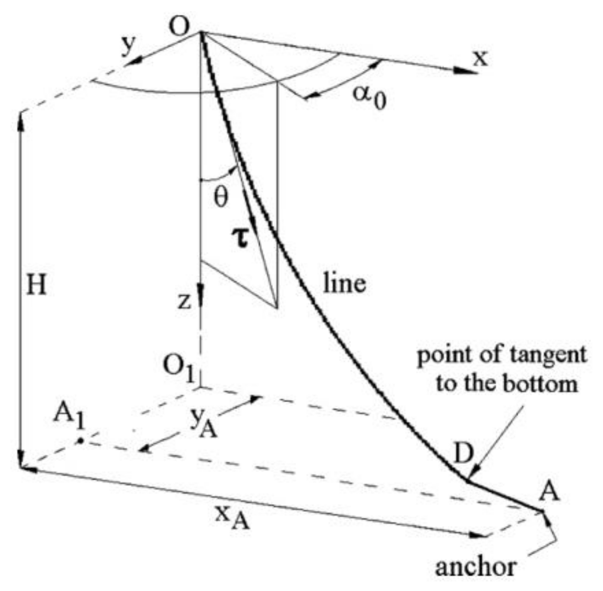
To obtain the dynamic response of a marine cable, theory and computation modeling are needed, which are shown in the following sections.

2.1. Theory

For the dynamic effects of the mooring cable release process, this paper focuses on three static equilibrium calculation methods (the fast static equilibrium calculation method, the analytical suspension line method, and the suspension line method), all of which have been applied to engineering problems, but they take into account different influencing factors and have different calculation efficiencies. In all three methods the suspension line theory is used, although there are some tradeoffs based on the traditional suspension line theory. Our comparison of the three methods will begin with the derivation process and initial assumptions of the suspension line theory. As the industry is already familiar with the classical suspension line method, only those portions of the classical suspension line theory related to the following contents are included here, just as shown in Figure 2.
In Figure 2, we illustrate the study of a specific micro-element, ds, on the cable. D and F represent the fluid force along the vertical and tangential directions of the cable element, respectively. The tension of the cable is T. The angle, φ, between the cable element and the water flow is the cable angle. The tensions dT and dφ are the small increments of tension on the cable element, ds, and the cable angle, φ, respectively. w is defined as the weight in water per unit of length of the cable, which is the importance of the line after deducting buoyancy. da is not subject to fluid pressure as it is situated at the two ends of the element. In order to calculate the buoyancy of the cable element based on its drainage volume, the fluid pressure at both ends has been considered. This correct term should be included in the force analysis of the cable element. The tension at the upper and lower ends of the cable element is deducted from ρgA(hz − dz) and ρgA(hz), where A is the cable’s cross-sectional area, ρ is the fluid density, g is the gravity of the cable micro-element, h is the water depth, and z is the seabed depth.
Figure 2 shows that, when these forces are in static equilibrium, the following equation relationship occurs:
In the normal direction of the cable element:
Td φ ρ gA ( h z ) d φ = ( wcos φ + D ) ds
In the tangent direction of the cable element:
dT ρ gAdz = ( wsin φ F ) ds
When the apparent tension T* = TρgA(hz) is introduced, the above equations can be written as follows:
T d φ = ( wcos φ + D ) ds
d T = ( wsin φ F ) ds
For the sake of brevity, the apostrophe * on the T is omitted.
The above two cable balancing equations are nonlinear, and analytical solutions are difficult to discover. Under certain conditions, it is possible to seek a simpler analytical solution. If a cable is heavy or the current velocity is small, the force acting on it is mostly gravity, and the fluid force may be neglected. Equations (3) and (4) can be simplified as follows:
Td φ = wcos φ ds
dT = wsin φ ds
Divide Equations (5) and (6):
ln T T 0 = φ 0 φ tan φ d φ = lnsec φ = ln cos φ 0 cos φ
Hence:
T = T 0 cos φ 0 cos φ
where T is the tension of the cable when the cable angle,  φ 0 , is 0.
By substituting Equation (8) into Equation (5), measuring from the origin point, and integrating from cable length s0 to cable length s (set the cable angles at the two places to be φ0 and φ, respectively), the following equation can be obtained:
s s 0 = φ 0 φ T 0 cos φ 0 w cos 2 φ d φ = T 0 cos φ 0 w ( tan φ tan φ 0 )
Let Th = T0cos φ0, hence:
s s 0 = φ 0 φ T 0 cos φ 0 w cos 2 φ d φ = T h w ( tan φ tan φ 0 )
The following equation can be obtained by substituting dx = dscos φ into Equation (5):
x x 0 = φ 0 φ T 0 cos φ 0 w cos φ d φ = T h w [ ln ( 1 cos φ + tan φ ) ln ( 1 cos φ 0 + tan φ 0 ) ]
Similarly, Equation (12) can be obtained by substituting dz = dssinφ into Equation (5):
z z 0 = φ 0 φ T 0 cos φ 0 sin φ w cos 2 φ d φ = T h w ( 1 cos φ 1 cos φ 0 )
Equations (11) and (12) are expressions between the cable length, the horizontal distance, and the vertical distance at any two points in the static equilibrium stage of a cable. If the lower limit of the integral is taken at the origin point, then the following is the case:
w T h x = ln ( 1 + sin φ cos φ )
If a = Th/w, then the following is the case:
x a = ln ( 1 + sin ϕ cos ϕ )
We can conclude the following:
sin h x a = tan ϕ
cos h x a = 1 cos ϕ
Thus, Equations (10) and (12) can be written as follows:
s = a sin h x a
z = a ( cos h x a 1 )
Equations (17) and (18) are catenary equations.
From Equations (17) and (18), we can obtain the following:
( z + a ) 2 = s 2 + a 2
s = z ( z + 2 a )
x = a cos h 1 ( z a + 1 )
Based on the fact that gravitational force is negligible when compared to fluid pressure, the above process derives from the traditional suspension line method. Using this method, a definite analytical solution can be obtained; therefore, the conventional suspension line method can be referred to as the analytical suspension line method.
The method considers gravitational and buoyancy forces as well as a cable’s axial elasticity, while overlooking a cable’s inertia force, drag force, additional mass force, bending stiffness, and torsional stiffness, in addition to end-point connection stiffness and pressure effects.
However, as discussed in the derivation process above, if fluid forces play a significant role in Equations (3) and (4) of the cable equilibrium then the derivation process is not valid. As a result, Equations (5) and (6) cannot be derived. Numerical integration is necessary in this case in order to take into account fluid forces at each time step.
This paper presents a suspension line method based on the traditional suspension line theory. In the expression above, it is similar to the conventional suspension line method, that is, the analytical suspension line method, in that both ignore the bending and torsional stiffness of a cable; however, the suspension method using numerical integration proposed in this paper considers gravity, buoyancy, wave as well as current resistance, inertia, and cable axial stiffness. Currently, this method is the primary method for static calculations of marine cables. In order to facilitate the distinction between the suspension line method described in the following description and the analytical suspension line method, it is clarified here that the suspension line method refers to this method.

2.2. Computation Modeling

The lumped mass method is a more general method of modeling and discretizing slender flexible components, such as marine pipelines, whose accuracy has been generally verified; hence, a mooring cable is modeled by using the lumped mass method in this paper. Initially, a cable is moored to a ship at its top. The top of the cable is initially attached to the bow of the vessel, and once static equilibrium is achieved it is removed from the bow. In terms of characteristics, the mooring cable has a length of 220 m, an outer diameter of 0.35 m, an inner diameter of 0.25 m, the modulus of elasticity is infinite, the linear density is 0.18 t/m, the Poisson’s ratio is 0.5, the bending stiffness is 120 kN/m2, the torsional stiffness is 80 kN/m2, and the axial stiffness is 700 MN. Cables have a mass coefficient of 1, a drag force coefficient of 1.2, and an inertial force coefficient of 0.008. As the discrete unit of this paper is 2 m, the mooring cable is discretized into 110 points of condensed mass.
This particular seabed has a depth of 100 m, a flat seabed, and a normal as well as tangential stiffness of 1000 kN/m/m2. We can obtain an approximate solution to this problem by combining the micro-amplitude wave theory and the Stokes wave theory. Many complex algebraic calculations are required, and the sea current cannot be considered when determining wave characteristics. Accordingly, Dean expressed wave motion as a stream function in 1965 and established the stream function theory. Based on the assumption that fluid is incompressible and that motion has potential, the following idea is proposed: Two boundary conditions govern the motion and dynamics of a fluctuating free water surface. Thus, the flow function applies to waves in any state of the sea. If other wave theories are used, they should be compared to the flow function theory in order to examine their validity. Consequently, to improve the accuracy of wave loading in this paper, the wave type has been chosen as the stream function. This means that the wave direction is 180 degrees, the wave height is 7 m, and the wave period is 8 s.
The OrcaFlex software [83] is used to conduct the analysis of three different methods. In OrcaFlex there are two temporal discretization schemes: explicit and implicit integration. The explicit time integration takes a constant time step to integrate forward. At the beginning of the simulation, after a preliminary static analysis, the initial positions and orientations of all of the nodes in the model are known. The forces and moments of all free bodies and nodes are calculated, including gravity, buoyancy, hydrodynamic force, hydrodynamic added mass, tension and shear, bending and moment, seabed friction, etc. For implicit integration, the generalized-α method is used. Forces, moments, damping, and weight are calculated in the same manner as explicit integration. Since the forces, displacements, velocities, and accelerations are unknown at the last time step, an iterative approach is required. To improve computational efficiency, a pre-simulation stage is usually preset in OrcaFlex. The simulation time at this stage is set to be no less than one wave period. In the modeling preparation stage, the wave dynamic parameters, ship motion, and current parameters are increased from 0 to a fixed value. In this way, the simulation can have a smooth start, reduce transient responses, and avoid long simulation runs.

3. Calculation Results

The configurations of a cable with different equilibrium calculation methods are shown in Figure 3, Figure 4 and Figure 5.

3.1. Fast Static Equilibrium Calculation Method

By ignoring the buoyancy, fluid drag forces, gravitational force per unit of length, and axial elasticity of the cable, as well as the bending, torsion, and joint contact forces between the cable and the seabed, the fast-counting static equilibrium algorithm improves convergence and saves computational time.
According to the fast static equilibrium calculation method, the following phenomena can be observed in the spatial morphology of the cable release process, which is shown in Figure 3.
Figure 3. Configuration of a cable with the fast static equilibrium calculation method.
Jmse 11 00764 g003
As the mooring cable falls vertically in the static equilibrium stage due to gravity alone, the upper part of the cable does not undergo repeated S-shaped bending. Due to the overlap in the length of a wide range, S-shaped repeated bending is primarily observed when the cable approaches the seabed. The bending occurs initially to one side, then in the opposite direction of the previous bending direction. Following a small range of sliding in the time domain and with low conduction, the final repeated bending area at the bottom of the seabed eventually exhibits the shape of an eight bow. Additionally, the initial touchdown area of the cable maintains a flat state parallel to the seabed throughout the dynamic simulation process. According to our analysis of this phenomenon, since the static equilibrium stage only takes into account the gravity of the towing cable and does not take into account the buoyancy and the dragging effects of the water, the cable is directly affected by gravity in its natural sagging state. After release, the cable will fall vertically. Once we have entered the dynamic simulation stage, the dragging force of the current and the wave force begin to exert an effect. Consequently, the cable begins to bend and twist repeatedly as a result of these combined forces.

3.2. Analytical Catenary Calculation Method

In contrast to the fast static equilibrium calculation method, the analytical catenary calculation method accounts for buoyancy in the static equilibrium calculation stage and the dynamic phase of the cable drop process, which is shown in Figure 4.
Figure 4. Configuration of a cable with the analytic catenary calculation method.
Jmse 11 00764 g004
From the viewpoint of morphological changes, after considering the movement of buoyancy in arriving at the static equilibrium, as opposed to numerical calculation methods that use the fast static equilibrium, the bottom of the cable will form eightfold half-horizontal angles at the beginning of the dynamic phase, whereas the numerical solution using the short equilibrium does not show this phenomenon as soon as the cable reaches the static equilibrium. Under the fast static equilibrium algorithm, the subsequent active descent phase is similar to the dynamic descent of the cable. As the cable approaches the seabed, it undergoes repeated bending in an S-shaped pattern due to its large overlap in length. Initially, the cable is bent to one side, and then to the opposite side from the previous bending step. They are transmitted sequentially down in the time domain. After bottoming out, the area of the final repeated bend slides into a small area on the seabed, assuming the shape of a figure eight. As a result of the half-horizontal eightfold angle formed in the leftmost part of the bottoming section, the cable eventually landed in a pattern that combined half-horizontal eightfolds and horizontal eightfolds.
It is found that the effect of the wave force in the dynamic simulation of the cable is not fully reflected following entry into the dynamic stage. This is regardless of whether the static equilibrium calculation method or the analytic catenary calculation method is used. These two methods do not take into account the drag and inertia forces.

3.3. Catenary Calculation Method

The catenary calculation method takes into account a cable’s gravity, buoyancy, wave drag, inertia, and axial stiffness when calculating the static equilibrium. In the stationary equilibrium phase, the wave force is composed of wave drag and inertia. This means that, in comparison with the first two methods of calculating the static equilibrium of the cable, the effect of waves on the change in the cable form during the static equilibrium stage is considered in the catenary calculation method. In the static equilibrium stage, the dynamic morphology of the cable is considerably different from the dynamic morphology of the other two methods. At the beginning of the fall, the upper part of the cable is stretched and bent considerably. This is after the calculation of the static equilibrium stage with the catenary calculation method. Aside from the repeated S-shaped bends of the cable in the descending stage, there will be vertical motion and repeated left as well as right swings. Upon consideration of the dragging force and inertia force of the wave, this vertical motion and repeated left-to-right oscillations were caused by the wave heave. These movements occurred throughout the entire release process, which is shown in Figure 5.
Figure 5. Configuration of a cable with the catenary calculation method.
Jmse 11 00764 g005
As a result of the combination of vertical motion and lateral oscillation, the trajectory of the cable in the falling process becomes very complex; additionally, as a result of this complex trajectory, the changes in cable morphology become very complex. The S-bending process involves looping the cable back to create a zero-shaped slewing knot that is laterally elongated. With repeated S-bends, three horizontal eights were eventually formed. These three horizontal eights overlap in height on the left side, while the right-side slides are staggered. It is likely that the cable will eventually form a complex form with three horizontal eights overlapping and a transversely elongated zero-shaped slewing knot at the joint of the diagonal eights.
Due to the different static equilibrium calculation methods, the dynamic lowering stage of the cable has very different characteristics depending on the static balance calculation method. It is unlikely that the cable will respond effectively to the wave and current load during the dynamic lowering process if only the gravity factor and the axial stiffness of the cable are considered during the static equilibrium stage (the fast static equilibrium calculation method). As long as the cable’s gravity, buoyancy, and axial stiffness are considered only in the static equilibrium stage (the analytical catenary method), then the effect of the cable on the sea current will be reflected in the dynamic balance lowering process; however, the dynamic characteristics will still be weakened as a result of wave loading. The characteristics of the cable during dynamic descent are closest to what they would be if gravity, buoyancy, wave–current drag, inertial forces, and the axial stiffness of the cable were taken into account when calculating the static equilibrium of the cable (the catenary method); however, although the cable release process is dynamic, the simulation and analysis of the dynamic approach are only possible once the static equilibrium has been achieved.

4. Conclusions

Marine composite mooring and towing lines are usually composed of lines, chains, buoys, and underwater objects. They are subject to wave, current, and other interactions, so it is necessary to predict their static configuration under different conditions from the early stages of the design process. So far, the static equilibrium calculation of marine cables has been developed to a high degree of accuracy and comprehensiveness; more and more methods take into account the effects of gravity, buoyancy, wave resistance, inertial forces, and the axial stiffness of the cable to ensure the accuracy of the characteristics of the cable during dynamic descent. Numerical integration based on the finite element method is the main method used in this study, which in this case is the suspension line method.
It should be noted that the consideration of too many factors in the static equilibrium stage will almost certainly increase the difficulty of convergence. Therefore, specific static equilibrium methods can be selected for specific marine engineering situations in order to simultaneously save calculation time and improve calculation accuracy. For example, when laying down marine pipelines in the sea without waves, the speed of laying down marine pipelines is slow and the dragging effect of currents is weak. Therefore, in order to reduce the calculation time as well as the difficulty of convergence of the model, one could choose the analytical suspension chain method in the static equilibrium stage. Moreover, this method ensures the relative realism of dynamic characteristics throughout the entire process by taking buoyancy into account. Furthermore, it improves the accuracy of the calculation while saving a considerable amount of time.
The conclusions obtained in this paper have certain reference value for guiding the dynamic simulation of pipelines in specific offshore engineering fields. The emphases of pipeline dynamic simulation are different in different marine engineering scenarios. Some focus on the mechanical properties of pipelines, while others focus on the spatial morphological changes in pipelines. These are all related to the calculation method of the pipeline static equilibrium stage, which is the precise value of the reviewed literature and present case study.

Author Contributions

Conceptualization, D.Z.; methodology, D.Z. and K.Z.; software, D.Z.; validation, B.Z. and Y.Z.; formal analysis, D.Z.; investigation, J.S.; resources, D.Z. and J.S.; data curation, K.Z.; writing—original draft preparation, D.Z.; writing—review and editing, B.Z.; visualization, K.Z.; supervision, H.J. and B.Z.; funding acquisition, D.Z. All authors have read and agreed to the published version of the manuscript.

Funding

This research was funded by the Program for Scientific Research Start-up Funds of Guangdong Ocean University, grant number 060302072101, the Zhanjiang Marine Youth Talent Project—Comparative Study and Optimization of Horizontal Lifting of Subsea Pipeline, grant number 2021E5011, and the National Natural Science Foundation of China, grant number 62272109.

Institutional Review Board Statement

Not applicable.

Informed Consent Statement

Not applicable.

Data Availability Statement

Not applicable.

Conflicts of Interest

The authors declare no conflict of interest.

References

  1. Lemon, S.G. Towed-array history, 1917–2003. IEEE J. Ocean. Eng. 2004, 29, 365–373. [Google Scholar] [CrossRef]
  2. Luo, Y.; Zhang, D. Dynamic analysis of an axially moving underwater pipe conveying pulsating fluid. Front. Mar. Sci. 2022, 9, 982374. [Google Scholar] [CrossRef]
  3. Simos, A.N.; Fujarra, A.L.C. Dynamic Tension on Mooring Lines. Comparison of Numerical and Experimental Results. In Proceedings of the Fourteenth International Offshore and Polar Engineering Conference, Toulin, France, 23–28 May 2004. [Google Scholar]
  4. Berteaux, H.O. Buoy Engineering; John Wiley and Sons: New York, NY, USA, 1976. [Google Scholar]
  5. Nakajima, T.; Motora, S.; Fujino, M. On the dynamic analysis of multi-component mooring lines. In Proceedings of the Offshore Technology Conference, Houston, TX, USA, 3–6 May 1982. [Google Scholar]
  6. Matha, D.; Schlipf, M.; Pereira, R.; Jonkman, J. Challenges in simulation of aerodynamics, hydrodynamics, and mooring-line dynamics of floating offshore wind turbines. In Proceedings of the Twenty-First International Offshore and Polar Engineering Conference, Maui, HI, USA, 19–24 June 2011. [Google Scholar]
  7. Matulea, I.C.; Năstase, A.; Tălmaciu, N.; Slămnoiu, G.; Gonçalves-Coelho, A.M. On the equilibrium configuration of mooring and towing cables. Appl. Ocean Res. 2008, 30, 81–91. [Google Scholar] [CrossRef]
  8. Abkowitz, M.A. Stability and Motion Control of Ocean Vehicles; Card Nr. 70-93041; Massachusetts Institute of Technology, The MIT Press: Cambridge, MA, USA, 1969. [Google Scholar]
  9. Chucheepsakul, S.; Huang, T. Static equilibrium of marine cables by a variational method. In Proceedings of the First ISOPE Pacific/Asia Offshore Mechanics Symposium, Seoul, Republic of Korea, 24–28 June 1990. [Google Scholar]
  10. Chen, L.; Basu, B.; Nielsen, S.R.K. Nonlinear periodic response analysis of mooring cables using harmonic balance method. J. Sound Vib. 2019, 438, 402–418. [Google Scholar] [CrossRef]
  11. Quan, W.; Chang, Q.; Zhang, Q.; Gong, J. Dynamics calculation for variable-length underwater cable with geometrically nonlinear motion. Ocean Eng. 2020, 212, 107695. [Google Scholar] [CrossRef]
  12. Zhanga, J.; Zhoua, X.L.; Guoa, J.J.; Wanga, J.H. Quasi-static Analysis of Mooring Line Tension Under Combined Impact of Wave, Current and Soil. In Proceedings of the Twenty-fourth International Ocean and Polar Engineering Conference, Busan, Republic of Korea, 15–20 June 2014. [Google Scholar]
  13. Kumar, P.; Ganguli, A.; Benipal, G.S. Empirical Validation of Free Vibration of Sagging Cables. ASPS Conf. Proc. 2022, 1, 1057–1063. [Google Scholar] [CrossRef]
  14. Such, M.; Jimenez-Octavio, J.R.; Carnicero, A.; Lopez-Garia, O. An approach based on the catenary equation to deal with static analysis of three dimensional cable structures. Eng. Struct. 2009, 31, 2162–2170. [Google Scholar] [CrossRef]
  15. Huang, T. A static equilibrium formulation including axial deformation for marine cables. In Proceedings of the Second International Offshore and Polar Engineering Conference, San Francisco, CA, USA, 14–19 June 1992. [Google Scholar]
  16. Watson, T.U.; Kuneman, J.E. Determination of the static equilibrium configuration of externally redundant submerged cable arrays. In Proceedings of the Offshore Technology Conference, Houston, TX, USA, 4–7 May 1975. [Google Scholar]
  17. Girón, A.R.C.; Corrêa, F.N.; Hernández, A.O.V.; Jacob, B.P. An integrated methodology for the design of mooring systems and risers. Mar. Struct. 2014, 39, 395–423. [Google Scholar] [CrossRef]
  18. Ja’e, I.A.; Ali, M.O.A.; Yenduri, A.; Nizamani, Z.; Nakayama, A. Optimisation of mooring line parameters for offshore floating structures: A review paper. Ocean Eng. 2022, 247, 110644. [Google Scholar]
  19. Nikan, O.; Golbabai, A.; Machado, J.T.; Nikazad, T. Numerical approximation of the time fractional cable model arising in neuronal dynamics. Eng. Comput. 2022, 38, 155–173. [Google Scholar] [CrossRef]
  20. da Silva, D.M.L.; Jacob, B.P.; Rodrigues, M.V. Implicit and explicit implementation of the dynamic relaxation method for the definition of initial equilibrium configurations of flexible lines. In Proceedings of the International Conference on Offshore Mechanics and Arctic Engineering, Hamburg, Germany, 4–9 June 2006. [Google Scholar]
  21. Neto, A.G.; de Arruda Martins, C. Structural stability of flexible lines in catenary configuration under torsion. Marine Struct. 2013, 4, 16–40. [Google Scholar] [CrossRef]
  22. Moe, G.; Arntsen, Ø. An analytic model for static analysis of catenary risers. In Proceedings of the Eleventh International Offshore and Polar Engineering Conference, Stavanger, Norway, 17–22 June 2001. [Google Scholar]
  23. Athisakul, C.; Phanyasahachart, T.; Klaycham, K.; Chucheepsakul, S. Static equilibrium configurations and appropriate applied top tension of extensible marine riser with specified total arc-length using finite element method. Eng. Struct. 2012, 34, 271–277. [Google Scholar] [CrossRef]
  24. Lepidi, M.; Gattulli, V. Static and dynamic response of elastic suspended cables with thermal effects. Int. J. Solids Struct. 2012, 49, 1103–1116. [Google Scholar] [CrossRef] [Green Version]
  25. Ma, G.; Sun, L.; Wang, H.; Ai, S. Nonlinear mechanical model for static analysis of stretched mooring line. In Proceedings of the Twenty-third International Offshore and Polar Engineering Conference, Anchorage, AK, USA, 30 June–5 July 2013. [Google Scholar]
  26. Yang, M.D.; Teng, B.I.N. Static and dynamic analysis of mooring lines by nonlinear finite element method. China Ocean Eng. 2010, 24, 417–430. [Google Scholar]
  27. Muhammad, N.; Ullah, Z.; Choi, D.H. A numerical procedure accounting for fluid drag forces and cable extensibility for the static response of mooring cables. Int. J. Steel Struct. 2018, 18, 293–303. [Google Scholar] [CrossRef]
  28. Sharma, A.K.; Sinha, S.S.; Kumar, R.; Saha, S.K. Semi-analytical solution for static and quasi-static analysis of an inextensible cable. Int. J. Solids Struct. 2022, 234, 111296. [Google Scholar] [CrossRef]
  29. Irvine, M. Cable Structures; (No. Sirsi) i9780486671277; Dover Publications: Mineola, NY, USA, 1992. [Google Scholar]
  30. Masciola, M.; Jonkman, J.; Robertson, A. Implementation of a multisegmented, quasi-static cable model. In Proceedings of the Twenty-Third International Offshore and Polar Engineering Conference, Anchorage, AK, USA, 30 June–5 July 2013. [Google Scholar]
  31. Wan, R.; Hu, F.; Tokai, T.; Matuda, K.O. A method for analyzing the static response of submerged rope systems based on a finite element method. Fish. Sci. 2002, 68, 65–70. [Google Scholar] [CrossRef] [Green Version]
  32. Wu, S. Adaptive dynamic relaxation technique for static analysis of catenary mooring. Mar. Struct. 1995, 8, 585–599. [Google Scholar] [CrossRef]
  33. Smith, R.J.; MacFarlane, C.J. Statics of a three component mooring line. Ocean Eng. 2001, 28, 899–914. [Google Scholar] [CrossRef]
  34. Zhu, X.; Yoo, W.S. Suggested new element reference frame for dynamic analysis of marine cables. Nonlinear Dynam. 2017, 87, 489–501. [Google Scholar] [CrossRef]
  35. Han, H.; Li, X.; Zhou, H.S. 3D mathematical model and numerical simulation for laying marine cable along prescribed trajectory on seabed. Appl. Math. Model. 2018, 60, 94–111. [Google Scholar] [CrossRef]
  36. Vaz, M.A.; Li, X.; Liu, J.; Ma, X. Analytical model for axial vibration of marine cables considering equivalent distributed viscous damping. Appl. Ocean Res. 2021, 113, 102733. [Google Scholar] [CrossRef]
  37. Bai, Y.; Zhang, D.; Zhu, K.; Zhang, T. Dynamic analysis of umbilical cable under interference with riser. Ships Offshore Struct. 2018, 13, 809–821. [Google Scholar] [CrossRef]
  38. Huang, S. Stability analysis of the heave motion of marine cable-body systems. Ocean Eng. 1999, 26, 531–546. [Google Scholar] [CrossRef]
  39. Chucheepsakul, S.; Srinil, N.; Petchpeart, P. A variational approach for three-dimensional model of extensible marine cables with specified top tension. Appl. Math. Model. 2003, 27, 781–803. [Google Scholar] [CrossRef] [Green Version]
  40. Zhu, Z.H. Dynamic modeling of cable system using a new nodal position finite element method. Int. J. Numer. Meth. Bio. Eng. 2010, 26, 692–704. [Google Scholar] [CrossRef]
  41. Zhu, K.; Zheng, D.; Cai, Y.; Yu, C.; Wang, R.; Liu, Y.; Zhang, F. Nonlinear hydrodynamic response of marine cable-body system under random dynamic excitations. J. Hydrodyn. 2009, 21, 851–855. [Google Scholar] [CrossRef]
  42. Xu, X.; Wang, S. A flexible-segment-model-based dynamics calculation method for free hanging marine risers in re-entry. China Ocean Eng. 2012, 26, 139–152. [Google Scholar] [CrossRef]
  43. Witz, J.A.; Tan, Z. Rotary bending of marine cables and umbilicals. Eng. Struct. 1995, 17, 267–275. [Google Scholar] [CrossRef]
  44. Witz, J.A.; Tan, Z. On the axial-torsional structural behaviour of flexible pipes, umbilicals and marine cables. Mar. Struct. 1992, 5, 205–227. [Google Scholar] [CrossRef]
  45. Wang, F.; Huang, G.; Deng, D. Dynamic response analysis of towed cable during deployment/retrieval. J. Shanghai Jiaotong Univ. (Sci.) 2008, 13, 245–251. [Google Scholar] [CrossRef]
  46. Vaz, M.A.; Patel, M.H. Three-dimensional behaviour of elastic marine cables in sheared currents. Appl. Ocean Res. 2000, 22, 45–53. [Google Scholar] [CrossRef]
  47. Jung, D.H.; Park, H.I.; Koterayama, W. A numerical and experimental study on dynamics of a towed low-tension cable. In Proceedings of the Twelfth International Offshore and Polar Engineering Conference, Kitakyushu, Japan, 26–31 May 2002. [Google Scholar]
  48. Niedzwecki, J.M.; Thampi, S.K. Snap loading of marine cable systems. Appl. Ocean Res. 1991, 13, 2–11. [Google Scholar] [CrossRef]
  49. Mavrakos, S.A.; Papazoglou, V.J.; Triantafyllou, M.S.; Hatjigeorgiou, J. Deep water mooring dynamics. Mar. Struct. 1996, 9, 181–209. [Google Scholar] [CrossRef]
  50. Kurniawan, A.; Yosi, M.; Arief, I.S.; Cahyagi, D. Design of marine cable installation for ocean current power plant in Toyopakeh Strait-Bali. In Proceedings of the 2017 International Conference on Advanced Mechatronics, Intelligent Manufacture, and Industrial Automation (ICAMIMIA), Surabaya, Indonesia, 12–14 October 2017. [Google Scholar]
  51. Huang, S. Dynamic analysis of three-dimensional marine cables. Ocean Eng. 1994, 21, 587–605. [Google Scholar] [CrossRef]
  52. Huang, S.; Vassalos, D. A semi-analytic treatment of three-dimensional statics of marine cables. Ocean Eng. 1993, 20, 409–420. [Google Scholar] [CrossRef]
  53. Ghadimi, R. A simple and efficient algorithm for the static and dynamic analysis of flexible marine risers. Comput. Struct. 1988, 29, 541–555. [Google Scholar] [CrossRef]
  54. Peltzer, R.D.; Rooney, D.M. Near wake properties of a strumming marine cable: An experimental study. J. Fluids Eng. 1985, 107, 86–91. [Google Scholar] [CrossRef]
  55. Chen, B.; Su, F.; Huo, C.F.; Zhang, R.B.; Yao, B.H.; Lian, L. Numerical investigation of the dynamics for low tension marine cables. J. Shanghai Jiaotong Univ. (Sci.) 2015, 20, 257–264. [Google Scholar] [CrossRef]
  56. Bian, A.; Zou, Z.; Zhou, H.W.; Zhang, J. Evaluation of multi-scale full waveform inversion with marine vertical cable data. J. Earth Sci. 2015, 26, 481–486. [Google Scholar] [CrossRef]
  57. Beasley, C.J.; Coates, R.T.; Flath, P.; Castellanos, C. Slanted cable marine acquisition and wave-equation receiver deghosting. In Proceedings of the 2015 SEG Annual Meeting, New Orleans, LA, USA, 18–23 October 2015. [Google Scholar]
  58. Peyrot, A.H. Marine cable structures. J. Struct. Div. 1980, 106, 2391–2404. [Google Scholar] [CrossRef]
  59. Yan, J.; Hu, H.; Lu, H.; Yin, Y.; Bu, Y.; Lu, Q. Experimental study on the influence of cross-section type of marine cable conductors on the bending performance. China Ocean Eng. 2022, 36, 629–637. [Google Scholar] [CrossRef]
  60. Marty, A.; Berhault, C.; Damblans, G.; Facq, J.V.; Gaurier, B.; Germain, G.; Soulard, T.; Schoefs, F. Experimental study of hard marine growth effect on the hydrodynamical behaviour of a submarine cable. Appl. Ocean Res. 2021, 114, 102810. [Google Scholar] [CrossRef]
  61. Chen, Y.; Li, J.; Wang, S.; Han, G.; Sun, Y.; Luo, W. Dynamic Modeling and Robust Adaptive Sliding Mode Controller for Marine Cable-Driven Parallel Derusting Robot. Appl. Sci. 2022, 12, 6137. [Google Scholar] [CrossRef]
  62. Cai, L.; Lin, J.; Liao, X. Residual life prediction of marine EPR cable under discontinuous operation. IET Gener. Transm. Distrib. 2020, 14, 6306–6311. [Google Scholar] [CrossRef]
  63. Rodríguez, L.Á.; Armesto, J.A.; Guanche, R.; Barrera, C.; Vidal, C. Simulation of marine towing cable dynamics using a finite elements method. J. Mar. Sci. Eng. 2020, 8, 140. [Google Scholar] [CrossRef] [Green Version]
  64. Casarella, M.J.; Parsons, M. Cable systems under hydrodynamic loading. Mar. Technol. Soc. J. 1970, 4, 27–44. [Google Scholar]
  65. Park, J.; Kim, N. Dynamics modeling of a semi-submersible autonomous underwater vehicle with a towfish towed by a cable. Int. J. Naval Arch. Ocean Eng. 2015, 7, 409–425. [Google Scholar] [CrossRef] [Green Version]
  66. Nguyen, T.D.; Egeland, O. Output Feedback Stabilization of Towed Marine Cable. In Proceedings of the OCEANS 2006—Asia Pacific, Singapore, 16–19 May 2006. [Google Scholar]
  67. Fukumoto, H.; Nakanishi, H.; Namita, Y. Dynamic response analysis of marine cable structure and its computational program. Doboku Gakkai Ronbunshu 1985, 356, 455–464. [Google Scholar] [CrossRef] [Green Version]
  68. Wildemann, E.R. Reduction of the Flow Induced Vibration Response of a Marine Cable by Altering the Cable Boundary Conditions; Massachusetts Institute of Technology: Cambridge, MA, USA, 1983. [Google Scholar]
  69. Westin, C.; Irani, R.A. Modeling dynamic cable–sheave contact and detachment during towing operations. Mar. Struct. 2021, 77, 102960. [Google Scholar] [CrossRef]
  70. Guo, L.; Yuan, Y.; Tang, W.; Xue, H. A numerical investigation on quasi-static configuration and nonlinear dynamic response characteristics of marine towing cable. Ocean Eng. 2021, 240, 110007. [Google Scholar] [CrossRef]
  71. Kamman, J.W.; Huston, R.L. Multibody dynamics modeling of variable length cable systems. Multibody Syst. Dyn. 2001, 5, 211–221. [Google Scholar] [CrossRef]
  72. Chatjigeorgiou, I.K.; Mavrakos, S.A. Cable dynamics for marine applications. In Springer Handbook of Ocean Engineering; Springer: Cham, Switzerland, 2016; pp. 875–906. [Google Scholar]
  73. Shin, H.K. Cable Dynamics for Marine Applications-Nonlinearities. J. Ocean Eng. Technol. 1990, 4, 35–40. [Google Scholar]
  74. Yang, N.; Jeng, D.S. Three-dimensional Analysis of Elastic Marine Cable during Laying. In Proceedings of the Eleventh ISOPE Pacific/Asia Offshore Mechanics Symposium, Shanghai, China, 12–14 October 2014. [Google Scholar]
  75. Prpić-Oršić, J.; Nabergoj, R. Nonlinear dynamics of an elastic cable during laying operations in rough sea. Appl. Ocean Res. 2005, 27, 255–264. [Google Scholar] [CrossRef]
  76. Athisakul, C.; Monprapussorn, T.; Chucheepsakul, S. A variational formulation for three-dimensional analysis of extensible marine riser transporting fluid. Ocean Eng. 2011, 38, 609–620. [Google Scholar] [CrossRef]
  77. Wang, Y.; Bian, X.; Zhang, X.; Xie, W. A study on the influence of cable tension on the movement of cable laying ship. In Proceedings of the OCEANS 2010 MTS/IEEE SEATTLE, Seattle, WA, USA, 20–23 September 2010; pp. 1–8. [Google Scholar]
  78. Delmer, T.N.; Stephens, T.C.; Tremills, J.A. Numerical simulation of cable-towed acoustic arrays. Ocean Eng. 1988, 15, 511–548. [Google Scholar] [CrossRef]
  79. Wang, W.; Zhang, S.; Wang, D.; Lin, L.; Zhu, X. Synchronous clamping control of marine umbilical cable tensioner. Proc. Inst. Mech. Eng. Part C J. Mech. Eng. Sci. 2013, 227, 2328–2336. [Google Scholar] [CrossRef]
  80. Wu, W.; Zhao, Y.; Gou, Y.; Lyu, B.C.; Lu, Q.Z.; Lu, Z.K.; Yan, J. An overview of structural design, analysis and common monitoring technologies for floating platform and flexible cable and riser. China Ocean Eng. 2022, 36, 511–531. [Google Scholar] [CrossRef]
  81. Zhu, X.; Yoo, W.S. Numerical modeling of a spar platform tethered by a mooring cable. Chin. J. Mech. Eng. 2015, 28, 785–792. [Google Scholar] [CrossRef]
  82. Bergdahl, L.; Palm, J.; Eskilsson, C.; Lindahl, J. Dynamically scaled model experiment of a mooring cable. J. Mar. Sci. Eng. 2016, 4, 5. [Google Scholar] [CrossRef] [Green Version]
  83. Orcina. OrcaFlex Manual. 2015. Available online: http://www.orcina.com/SoftwareProducts/OrcaFlex/Validation/index/.pdf (accessed on 1 January 2015).
Figure 1. The equilibrium configuration of a mooring cable [7].
Jmse 11 00764 g001
Figure 2. Diagram of cable micro-element force.
Jmse 11 00764 g002
Disclaimer/Publisher’s Note: The statements, opinions and data contained in all publications are solely those of the individual author(s) and contributor(s) and not of MDPI and/or the editor(s). MDPI and/or the editor(s) disclaim responsibility for any injury to people or property resulting from any ideas, methods, instructions or products referred to in the content.

