Vibration Control of Marine Top Tensioned Riser with a Single Tuned Mass Damper

1
Key Laboratory for Mechanics in Fluid-Solid Coupling Systems, Institute of Mechanics, Chinese Academy of Science, Beijing 100190, China
2
School of Engineering Science, University of Chinese Academy of Sciences, Beijing 100049, China
3
Aker Solutions, Houston, TX 77042, USA
*
Author to whom correspondence should be addressed.
J. Mar. Sci. Eng. 2020, 8(10), 785; https://0-doi-org.brum.beds.ac.uk/10.3390/jmse8100785
Submission received: 17 August 2020
/
Revised: 28 September 2020
/
Accepted: 28 September 2020
/
Published: 9 October 2020
(This article belongs to the Special Issue Safe, Secure and Sustainable Oil and Gas Drilling, Exploitation and Pipeline Transport Offshore)
Abstract
:The study of the Tuned Mass Damper (TMD) on Top Tensioned Risers (TTRs) through the application of numerical analysis is of great significance for marine engineering. However, to the best knowledge of the author, neither the in-field riser data nor the ocean current data used in published papers were from engineering design, so the research results provide limited guidance to the actual engineering project. In view of this problem, this study designed a single TMD to suppress the vibration of the engineering TTR under the action of the actual ocean current. First, the dynamic model of a riser-TMD system was established, and the modal superposition method was used to calculate the model. The non-resonant modal method of the flexible structure was used to design the TMD parameters for the engineering riser. Ocean current loading in the South China Sea was then applied to the riser. The vibration of the riser without and with TMD was compared. The result showed that TMD could effectively reduce the vibration response of the riser. When compared without TMD, the maximum value of displacement envelope and the RMS displacement were reduced by 26.70% and 17.83% in the in-line direction, respectively. Moreover, compared to without TMD, the maximum value of displacement envelope and RMS displacement were decreased by 17.01% and 22.05% in the cross-flow direction, respectively. In the in-line direction, the installation position of TMD on the riser was not sensitive to the effect of the displacement response; meanwhile, in the cross-flow direction the installation position of TMD on the riser was more sensitive to the effect of the displacement response.
1. Introduction
Suppressing the vibration of marine risers is a popular research direction. Spiral strakes, fairings, or other forms of passive vibration suppression devices are usually installed on the riser to suppress vibration [1]. The most commonly installed type is the helical strake. Strakes can destroy vortex shedding in the flow direction and reduce the effect of the vortex on the riser, which is a method to reduce the energy input. In contrast to passive vibration suppression devices, another device such as the tuned mass damper (TMD) can increase the energy consumption. TMDs are widely used in the field of civil engineering, such as in truss bridges [2], high-rise buildings [3], high towers [4], and structures.
Although some scholars have conducted TMD research on marine risers, they are still in the research state of numerical analysis and preliminary laboratory tests, and there is still a long way to go before applications [1,5,6]. Jaiswal [5] carried out an experimental study in a towed pool at MIT and numerically analyzed the effect of the stiffness of the TMD on the vibration displacement of the flexible riser. The results showed that the TMD could reduce the vibration displacement of the flexible riser. However, the author did not show the detailed experimental results so far. The slenderness ratio of the experimental model was 7.62 = 0.381 m/0.05 m and the Cauchy number was [7], similar to that of a rigid cylinder. Nikoo [6] used a pipe-in-pipe (PIP) instead of a traditional TMD to conduct numerical research on vortex-induced vibration suppression, and the results showed that 84% of the vortex-induced vibration could be suppressed. The slenderness ratio of its numerical model was in the range of 5–13, which is different from the slenderness ratio of engineering marine flexible risers, 102–103. Obviously, in the above article, the riser was a rigid structure, but the actual marine riser was a flexible structure, which caused the TMD to suppress the vibration effect of the riser to be exaggerated. As the TMD is usually designed for a certain resonant mode (target resonant mode), when the structure is flexible the tuned absorber not only experiences the support motion of the resonant mode, but also the support motion of other usually higher-frequency modes, and only a part of the force transmitted by the absorber enters the target resonant mode. When the structure is rigid, the tuned absorber only experiences the support motion of the resonant mode [8]. Therefore, the TMD suppresses the vibration effect of rigid risers better than the vibration effect of flexible risers.
Chaojun [1] studied the suppression of experimental riser vibration in the Gulf of Mexico using TMD and a semi-active tuned mass damper (STMD) through numerical analysis, and analyzed the dynamic response displacements under uniform flow and the Gulf stream. The results showed that the STMD’s vibration suppression effect was better than the TMD’s vibration suppression effect. However, the TMDs and STMDs were evenly distributed along the entire length of the flexible riser, which would lead to the installation of many damper components. The increase in the cross-sectional area of the damper cannot be ignored. This results in a larger load on the riser, a greater installation difficulty, difficulty in maintenance, and a higher cost.
In summary, due to the lack of engineering data in the numerical calculation, the actual effect of TMDs in suppressing riser vibration cannot be accurately quantified, so the practical guidance of the calculation results for the project is also limited. Accurate numerical calculation is the basis of engineering application. Therefore, this study uses a TMD to suppress marine flexible riser vibration in the actual ocean current load, and quantitatively analyzes the vibration suppression effect of the TMD.
The structure of the paper is as follows. Section 2 establishes the dynamic model of the TMD acting on flexible marine risers. Section 3 uses the modal superposition method to carry out numerical analysis on a flexible marine riser such as a Top Tensioned Risers (TTR). In Section 4, the numerical results are discussed. The conclusion is in Section 5.
2. Dynamic Model of TTR Marine Riser with TMD
The tuned mass damper (TMD) consists of a ring, a viscous damper, and a spring. It is installed on the outer surface of the riser, as shown below in Figure 1.
Vibration control equation in the XY plane:
where y represents the transverse displacement of the riser. The vibration control equation is also valid in the x-direction. z represents the length position. t represents the time. represents the bending stiffness, and T is the tension. mz represents the uniform mass per unit length of the riser. c represents the structural damping coefficient. represents the transverse force per unit length. represents the transverse force of TMD. is the Dirac function. represents the spring stiffness of the TMD, and represents the mass of TMD. and represent the TMD transverse displacement and the transverse displacement of the riser at time t and riser position s, respectively. represents the damping coefficient of TMD.
The transverse force per unit length of Equation (1) can be decomposed into the drag force in the in-line direction and the lift force in the cross-flow direction [9,10], as follows:
where is the sea water density. , is the drag force and lift force coefficient. is the velocity of the current. D is the diameter of the riser. The non-dimensional vortex shedding frequency is . is the St Number, usually taken as 0.2. AD is 20% of the first term of fD (z,t). and are the phase angles.
The boundary conditions are simply supported; the displacement is 0, and the bending moment is 0, as shown below:
Since the marine riser’s vibration is a small amplitude, the modal superposition method is used to solve the above partial differential equation. First, the natural frequency and mode are calculated, and the non-conservative force in Equation (1) is set as 0, then one obtains:
Assume that the solution of formula (6) has the form:
where represents the mode shape. represents the mode displacement.
Inserting Equation (7) into Equation (6),
where w is unknown. “” denotes the derivative of position z, and “.” denotes the derivative of time. t.
The boundary condition Equation (5) becomes:
Introducing hypothesis into Equation (8), we obtain:
The above Equation is a quartic equation of one element, and the four roots can be solved.
Thus, . After further simplification, using trigonometric and hyperbolic functions to replace the exponential form, we get:
where , .
Bringing the boundary condition Equation (9) into the above formula, we get . Because , so . Further, we get the natural frequency wn, and the mode shape .
Since the displacement y (z,t) is a combination of any number of modals, the expression of y (z,t) is:
Bringing the mode shape into Equation (10), one obtains:
Taking Equation (11) into Equation (1) and simplifying it, we obtain:
To simplify the calculation complexity, we set the structural damping c in the modal damping ratio:
According to the characteristics of trigonometric functions,
Multiply each term of Equation (12) by , integrate from 0 to L, and take Equations (13) and (14) into Equation (12), and we get:
After further simplification, we can obtain:
where the Nth order mode mass is , and the Nth order mode force is .
The displacement of the riser connected to the TMD is . Bring the displacement into Equation (2), where , and we obtain:
Simultaneously in (16) and (17), the dynamic equations of the system can be obtained with infinite degrees of freedom:
3. Numerical Analysis
3.1. Establishing Numerical Equations
When the mode superposition method is used in the project, the mode mass participation coefficient is required to be above 90% [11], so N is taken as the first five orders, and the mode mass participation coefficient is 92.31%.
Sorting out the above formula, we get the following:
where .
3.2. Select Model Parameters
The design of TMD has a large degree of freedom. In this paper, TMD is designed according to the design method proposed in [8], which considers the non-resonant modal contribution of flexible structures. The first-order modal damping ratio of a system consisting of a riser and a TMD is set to , and the remaining parameters are shown in Table 1 and Table 2 below.
The data is based on actual measurement data in the South China Sea for one year, and the depth is close to 1000 m, as shown in Figure 2. The data is a mixture of waves and currents. Since it cannot be separated and the current is dominantly away from the water surface, it is considered to be all ocean currents. The direction of the current is not exactly the same in the whole water depth, and the direction of the current is opposite in most months. Most ocean currents are negative at a depth of (−300,0) m and positive at a range of (−1000,−300) m. The negative velocity is greater than the positive velocity, the (−100,0) m velocity near the sea surface has the highest velocity, and the (−800, −1000) m velocity near the seafloor is almost zero. The max speed of the current in December is −35 cm/s. Compared with the uniform flow and shear flow often used previously in riser calculation, the actual operating current velocity in the field is not large, but the flow direction in full depth is more than a single direction and can be the opposite. It can be seen that the actual current is complicated.
The riser calculation is based on the most unfavorable December current data. The two directions’ dynamic response are calculated, respectively, for the in-line (y) direction and the cross-flow (x) direction. We take the drag force fD (z,t) of Equation (4) into Equation (20) to calculate the dynamic response in the in-line direction, and take the lift force fL (z,t) of Equation (4) into Equation (20) to calculate the dynamic response in the cross-flow direction. The initial state is static, the displacement is 0, the velocity is 0, and the acceleration is 0. Using the numerical integration Newmark-β method, α = 0.5, β = 0.25, and the average constant acceleration method is unconditionally stable.
4. Numerical Results
4.1. In-Line Direction
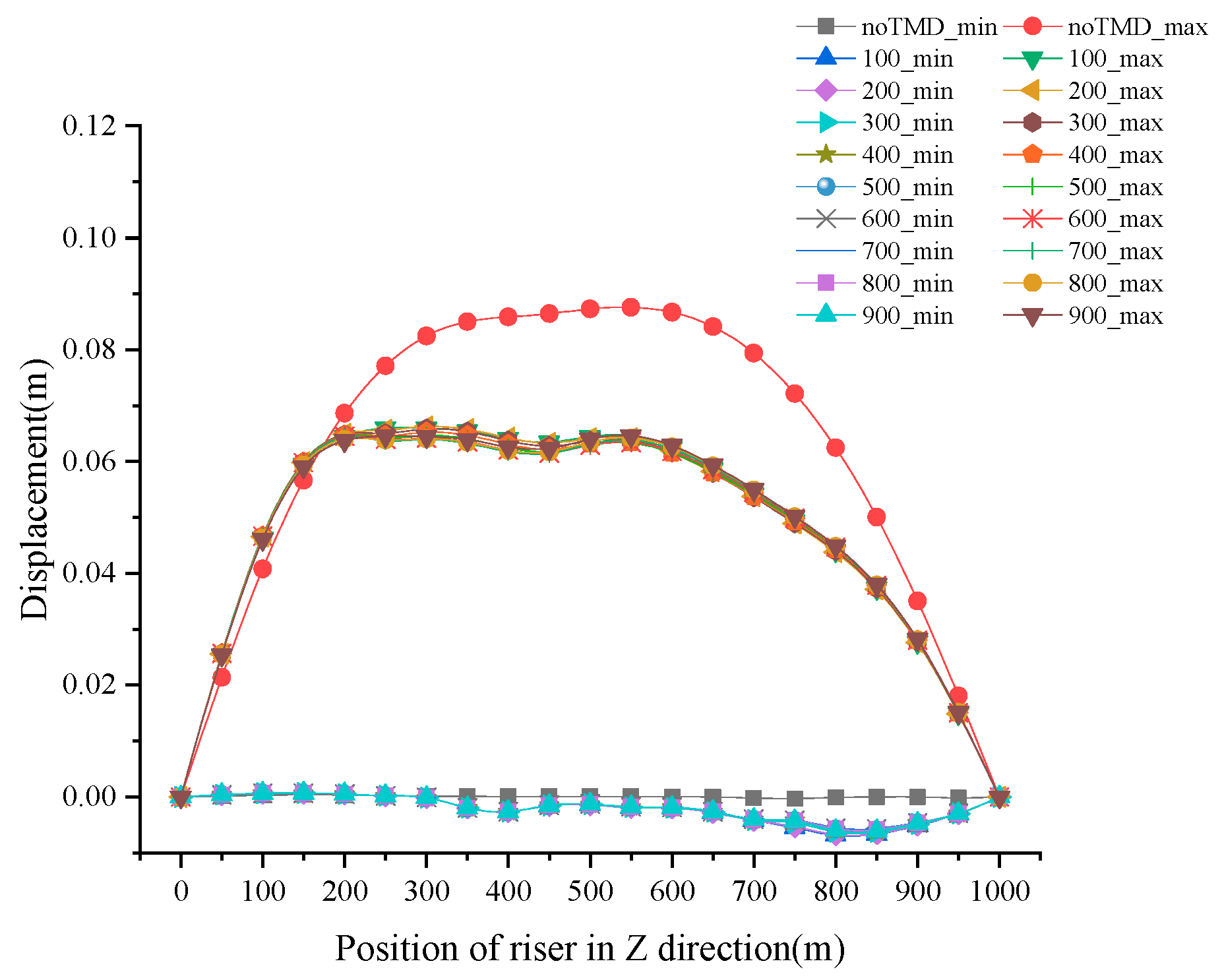
The influence of the TMD installation position on the vibration of the riser is analyzed. Figure 3 shows the displacement envelope without and with the TMD installed in different positions (100–900 m, every 100 m). It can be seen that, without TMD, the maximum value of displacement envelope is 0.0876 m at 550 m, and the minimum displacement envelope value is −0.0003 m at 750 m.
The target mode of TMD design is mode 1. The maximum displacement of the mode shape of mode 1 is at the center of the riser (500 m). Therefore, in theory, the TMD installed in the center of the riser is the best place to control the riser vibration. However, the calculation shows that the maximum value of displacement envelope of TMD installed at 800 m is the smallest. Moreover, the displacement value at 550 m is 0.0642 m, which is 26.70% lower than that of the riser without TMD. The best installation of TMD at 800 m instead of at 500 m is due to the unevenly distributed current.
The riser displacement envelope value of TMD installed at any position of (0,1000) m is smaller than the riser displacement envelope value without TMD. Besides this, the difference in the displacement envelope value of the riser installed at any position is small and almost coincident. Moreover, the maximum difference is only 3.49% when the TMD is installed at 200 m and 700 m.
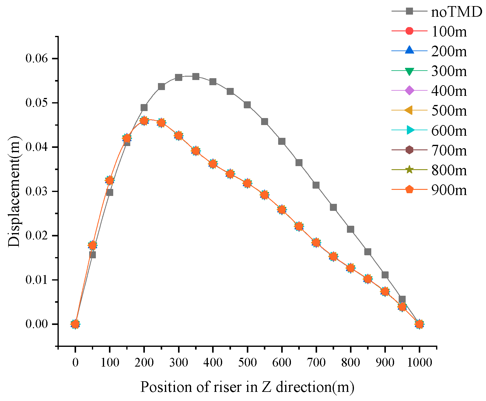
Figure 4 is the root mean square (RMS) diagram of the vibration displacement of the riser without the TMD and the riser with the TMD installed in different positions (100–900 m, every 100 m). The maximum displacement response without the TMD is 0.0559 m at 350 m, while the maximum displacement response with the TMD is 0.0459 m at 200 m, and the maximum reduction in the displacement is 17.83%. Thus, the position of the maximum displacement of the two is different. The displacement of the TMD installed at (0,150) m is slightly larger than that without the TMD, while the displacement of the TMD installed at (150,1000) m is significantly smaller than that without the TMD. It can be seen that the TMD installation can effectively reduce the RMS displacement of the riser.
4.2. Cross-Flow Direction
Figure 5 shows the envelope diagram of vibration displacement of riser when the TMD is installed at different positions. Because there is only current and no wave, the envelope diagram shows a symmetrical figure with the displacement of 0 axes—that is, the positive and negative envelope values are symmetrical. The displacement envelope value without TMD completely envelops the displacement envelope value with TMD. Therefore, the TMD reduces the displacement response. Specifically, when the TMD is not installed, the maximum value of displacement envelope is 0.0911 m at 700 m, and the minimum value is −0.0911 m at 700 m. While the TMD is installed at 400 m, the maximum value of displacement envelope is 0.0756 m, which is 17.01% lower than the displacement without TMD, and the minimum displacement envelope value is −0.0762 m in the same position, which is 16.36% lower than the displacement without the TMD.
Figure 6 shows the RMS diagram of the vibration displacement of the riser in the cross-flow direction when the TMD is installed at different positions. When the TMD is not installed, the vibration displacement is the largest, which is 0.0390 m at 700 m. While the TMD is installed, the vibration displacement becomes smaller. In other words, with the TMD installed at 400 m, it is 0.0304 m at 700 m in the z-direction, which is 22.05% lower than that without the TMD. Besides this, the displacement without the TMD at 500 m in the z-direction is 0.0370 m, and the displacement with the TMD installed at 500 m in the z-direction is 0.0234 m, which is 38.38% lower than the displacement without the TMD.
The TMD installation position has different effects on the displacement suppression in the in-line and cross-flow directions. Specifically, in the in-line direction, the installation position of the TMD is not sensitive to the vibration displacement control of the standpipe. However, in the cross-flow direction, the installation position of the TMD is more sensitive to the vibration displacement control of the riser. For example, in Figure 5, when the TMD is installed at 100 and 400 m in the z-direction, its maximum displacement envelope is 0.0865 and 0.0756 m, respectively. Compared with the displacement without the TMD, the decrease is 5.05% and 17.01%. The displacement reduction effect of installing TMD at 400m is 3.37 times as much as that of installing TMD at 100m.
5. Conclusions
In this study, a single TMD was used to suppress the vibration of the engineering TTR under the action of the actual ocean current. The dynamic model of a riser-TMD system was established, and the model was calculated using the modal superposition method. The influence of TMD on the vibration displacement of the riser under the South China Sea current was numerically and quantitatively analyzed, which is very helpful for engineering applications. We drew the following conclusions:
- The TMD could effectively restrain the vibration displacement of the riser. When compared to the condition without the TMD, the maximum value of displacement envelope and the RMS displacement were reduced by 26.70% and 17.83% in the in-line direction, respectively. Besides, compared to without the TMD, the maximum value of displacement envelope and the RMS displacement were decreased by 17.01% and 22.05% in the cross-flow direction, respectively.
- In the cross-flow direction, the vibration displacement control was sensitive to the TMD installation position, and the TMD installation should be near the best place (at 400 m in the z-direction of a 1000 m riser); but in the in-line flow direction, the vibration displacement control was not sensitive to the TMD installation position.
The next step is to prepare for experimental verification.
Author Contributions
Conceptualization, J.S., T.W., and W.C.; data curation, J.S.; formal analysis, J.S. and T.W.; funding acquisition, W.C.; investigation, S.G.; methodology, J.S. and D.Y.; project administration, W.C.; resources, W.C.; software, J.S. and D.Y.; supervision, W.C.; validation, T.W. and S.G.; visualization, J.S. and D.Y.; writing—original draft, J.S. and T.W.; writing—review and editing, W.C., J.S., S.G., and D.Y. All authors have read and agreed to the published version of the manuscript.
Funding
This research was funded by the Strategic Priority Research Program of the Chinese Academy of Sciences, grant number XDA22000000.
Acknowledgments
The authors thank the editors and anonymous reviewers for their assistance.
Conflicts of Interest
The authors declare no conflict of interest.
References
- Chaojun, H. Structural Health Monitoring System for Deepwater Risers with Vortex-Induced Vibration: Nonlinear Modeling, Blind Identification, Fatigue/Damage Estimation and Vibration Control. Ph.D. Thesis, Rice University, Houston, TX, USA, 2013. [Google Scholar]
- Hoang, N.; Fujino, Y.; Warnitchai, P. Optimal tuned mass damper for seismic applications and practical design formulas. Eng. Struct. 2008, 30, 707–715. [Google Scholar] [CrossRef]
- Elias, S.; Matsagar, V. Wind response control of tall buildings with a tuned mass damper. J. Build. Eng. 2018, 15, 51–60. [Google Scholar] [CrossRef]
- Kwok, K.C.S.; Samali, B. Performance of tuned mass dampers under wind loads. Eng. Struct. 1995, 17, 655–667. [Google Scholar] [CrossRef]
- Jaiswal, V. Effect of Traveling Waves on Vortex-Induced Vibration of long Flexible Cylinders. Ph.D. Thesis, Massachusetts Institute of Technology, Cambridge, MA, USA, 2009. [Google Scholar]
- Nikoo, H.M.; Bi, K.; Hao, H. Passive vibration control of Pipe-In-Pipe (PIP) systems subjected to Vortex Induced Vibration (VIV). In Proceedings of the 27th International Ocean and Polar Engineering Conference, San Francisco, CA, USA, 25–30 June 2017; International Society of Offshore and Polar Engineers: Mountain View, CA, USA, 2017; p. 6. [Google Scholar]
- Gosselin, F.; de Langre, E.; Machado-Almeida, B.A. Drag reduction of flexible plates by reconfiguration. J. Fluid Mech. 2010, 650, 319–341. [Google Scholar] [CrossRef] [Green Version]
- Krenk, S.; Høgsberg, J. Tuned mass absorber on a flexible structure. J. Sound Vib. 2014, 333, 1577–1595. [Google Scholar] [CrossRef]
- Faltinsen, O.M. Sea Loads on Ships and Offshore Structures; Faltinsen, O.M., Ed.; Cambridge University Press: Cambridge, UK; New York, NY, USA, 1990. [Google Scholar]
- Blevins, R.D. Flow-Induced Vibration; Van Nostrand Reinhold: New York, NY, USA, 1977. [Google Scholar]
- Wilson, E.L. Three-Dimensional Static and Dynamic Analysis of Structures; Computers and Structures: Berkeley, CA, USA, 2002. [Google Scholar]
Figure 1.
Schematic of the TMD and TTR model.

Figure 2.
Typical current velocity map from January to December in the South China Sea.

Figure 3.
Envelope diagram of the vibration displacement of the riser in the in-line direction when the TMD is installed in different positions.
Figure 3.
Envelope diagram of the vibration displacement of the riser in the in-line direction when the TMD is installed in different positions.

Figure 4.
RMS of the vibration displacement of the riser in the in-line direction when the TMD is installed at different positions.
Figure 4.
RMS of the vibration displacement of the riser in the in-line direction when the TMD is installed at different positions.

Figure 5.
Envelope diagram of vibration displacement of the riser in the cross-flow direction when the TMD is installed at different positions.
Figure 5.
Envelope diagram of vibration displacement of the riser in the cross-flow direction when the TMD is installed at different positions.

Figure 6.
RMS of the vibration displacement of the riser in the cross-flow direction when the TMD is installed at different positions.
Figure 6.
RMS of the vibration displacement of the riser in the cross-flow direction when the TMD is installed at different positions.


Table 1.
Risers and TMD parameter table.
| Parameters | Value | Parameters | Value |
|---|---|---|---|
| Riser Length L (m) | 1000 | Outside Diameter of Riser (m) | 0.2 |
| Mass Per Unit Length (kg/m) | 15 | Sea Water Density (kg/m3) | 1024 |
| Structural damping ratio % | 5 | Flexural rigidity EI (N/m2) | 4 × 10⁹ |
| Pretension F (N) | 1.2 × 10⁶ | Drag coefficient Cd | 1 |
| Drag force amplitude AD | 0.2 | phase angle α | 0 |
| Lift force coefficient CL | 1 | phase angle β | 0 |
| TMD Mass (kg) | 306 | TMD damping ratio % | 10.1 |
| TMD spring stiffness (N/m) | 245 | TMD mass/Riser full length mass | 0.02 |
Table 2.
Natural vibration frequency of the riser (Hz).
| Modal Order | 1 | 2 | 3 | 4 | 5 |
|---|---|---|---|---|---|
| Natural vibration frequency | 0.1437 | 0.3009 | 0.4830 | 0.6989 | 0.9546 |
© 2020 by the authors. Licensee MDPI, Basel, Switzerland. This article is an open access article distributed under the terms and conditions of the Creative Commons Attribution (CC BY) license (http://creativecommons.org/licenses/by/4.0/).
Share and Cite
MDPI and ACS Style
Song, J.; Wang, T.; Chen, W.; Guo, S.; Yan, D. Vibration Control of Marine Top Tensioned Riser with a Single Tuned Mass Damper. J. Mar. Sci. Eng. 2020, 8, 785. https://0-doi-org.brum.beds.ac.uk/10.3390/jmse8100785
AMA Style
Song J, Wang T, Chen W, Guo S, Yan D. Vibration Control of Marine Top Tensioned Riser with a Single Tuned Mass Damper. Journal of Marine Science and Engineering. 2020; 8(10):785. https://0-doi-org.brum.beds.ac.uk/10.3390/jmse8100785
Chicago/Turabian StyleSong, Jixiang, Tao Wang, Weimin Chen, Shuangxi Guo, and Dingbang Yan. 2020. "Vibration Control of Marine Top Tensioned Riser with a Single Tuned Mass Damper" Journal of Marine Science and Engineering 8, no. 10: 785. https://0-doi-org.brum.beds.ac.uk/10.3390/jmse8100785
Note that from the first issue of 2016, this journal uses article numbers instead of page numbers. See further details here.