Reconfiguring Passenger Ship Internal Environment for Damage Stability Enhancement


Maritime Safety Research Centre, Department of Naval Architecture, Ocean and Marine Engineering, University of Strathclyde, Glasgow G4 0LZ, UK
*
Author to whom correspondence should be addressed.
J. Mar. Sci. Eng. 2020, 8(9), 693; https://0-doi-org.brum.beds.ac.uk/10.3390/jmse8090693
Submission received: 14 July 2020
/
Revised: 13 August 2020
/
Accepted: 27 August 2020
/
Published: 7 September 2020
(This article belongs to the Special Issue Feature Reviews in Marine Science and Engineering)
Abstract
:The traditional risk control option adopted in naval architecture to meet safety-related objectives is by regulations, targeting damage limitation, nominally instigated in the wake of maritime accidents claiming heavy loss of life. These primarily concern the introduction of watertight bulkheads, i.e., permanent (passive) reconfiguration of the internal ship environment to enhance damage stability. This has been the most common measure, manifesting itself in the wake of every serious flooding accident since the beginning, back in the 19th century. However, traditional flooding protection through watertight subdivision, to an extent dictated by IMO regulations, has a physical limit which, if exceeded, a safety plateau is reached. This is currently the case and with damage stability standards progressively increasing, the safety gap between existing and new ships is dangerously widening and with design stability margins progressively eroding, stability management is unsustainable, leading to loss of earnings at best. The need for managing the residual risk through active intervention/protection over the life-cycle of the vessel drives industry to searching and adopting a new normal. This new normal is the innovation being explained in this paper by addressing safety enchantment through a systematic reconfiguration of the ship environment for passive and active protection in flooding accidents. In this respect, the “design-optimal” internal arrangement of a vessel, is adapted and reconfigured, using passive and active containment systems for flooding incidents, in the form of high-expansion foam products. The innovation is briefly explained, claiming transformational reduction in flooding risk in the most cost-effective way available. To support wider understanding and appreciation for the latter, the paper critically reviews the whole evolution of internal ship space reconfiguration, chronologically and systematically, concluding that new technological developments and breakthroughs will bring sustainable changes to the traditional evolutionary maritime safety enhancement.
1. Introduction
The term “reconfiguration” is meant to imply the evolutionary process involved in passive and active damage protection, following accidental damage of the ship hull by reconfiguring the internal space of a ship. This, in turn, is linked inextricably to ship stability quantification and provision and, in particular, stability when the ship hull is damaged as a result of collision or grounding accidents. The question as to how to quantify ship stability has been addressed since ca 250 B.C. by Archimedes [1,2], although the first attempts to crystallize these principles were only made in the 17th/18th centuries, when a concept of ship stability measure, the metacentric height, or GM as it is known today, was introduced by Paul Hoste in 1698 [3,4]. This concept was later elaborated further in a more widely acknowledged exposition by Pierre Bouguer [5], who introduced in 1746 the actual term “metacenter”. Leonhard Euler focused in 1749 on the righting moment at a particular angle of the heel as a better measure of stability [6], but it was George Atwood who eventually demonstrated in 1798 that such a measure can be derived for any angle [7], inventing thereby the GZ curve. Milestones on stability quantification, thereafter, were set by Canon Moseley’s concept of using the area under a GZ curve as a better measure of ship stability in 1850 [8], and Jaakko Rahola’s propositions to use a function of the GZ curve to express the ability of a ship to stay in functional equilibrium after flooding in 1939, or in the context of this paper, how to reconfigure the internal ship space for damage protection [9]. The emphasis, however, was on global ship parameters rather than the detail of the internal ship environment, which is the key determinant of reconfiguration of such environment for passenger ships. His approach, therefore, influenced all subsequent developments for all ship types, an issue, which Rahola, definitely did not think about at the time.
As advances in identifying “stability” parameters progressed, the legislation process for implementation of any such “technicalities” has surprisingly been slow, even though the need for some “legal” safety instruments was not realized for many centuries. First attempts to introduce governmental intervention were in place since ancient times, e.g., ban on sailing in winter (15 September to 26 May) in Rome during the Roman Empire (27 BC–AD 476/1453), which was in force in some places even as late as the 18th century, or the first recorded regulations on load line in the Middle Ages (cross marked on each ship) in Venice in 1255, or the first system of survey inspections imposed by the Recesses of the Diet of the Hanseatic League of 1412. However, only during the Industrial Revolution of 19th century with the introduction of steam-powered engines on-board ships, steel hulls, and rapid escalation of sea trade to the dimension of an “industry” did the true face of risk encountered by shipping start to show: During the winter of 1820 alone, more than two thousand ships were wrecked in the North Sea, causing the death of 20,000 people in one year, with some 700–800 ships being lost annually in the UK on average. Such a loss toll prompted the main maritime nations of the time, France and the UK, to exercise their policy-making powers to introduce accident-preventive regulations, to great opposition from the industry. Of note are Colbert’s Naval Ordinance, instituted by a Royal Declaration of August 17 1779 in France, which introduced again the office of huissier-visiteur, a surveyor, and the Merchant Shipping Act of 1850 (reinforced by the government in 1854, amended by the Act of 21 December 1906) in the United Kingdom, which obliged the Board of Trade to monitor, regulate, and control all aspects of safety and working conditions of seamen. The latter implemented also the load line requirements, which were applied to all vessels, including foreign ships visiting UK ports.
It was the sinking of the Titanic, however, on 14 April 1912 after a collision with an iceberg, causing the death of some 1500 people, which provided the catalyst for the adoption on 20 January 1914 of the first International Convention for the Safety of Life at Sea (SOLAS), which gained international recognition. The SOLAS Convention was subsequently revised and adopted four times since then, namely in 1929, 1948, 1960, and 1974, with the latter still in force today and allowing a flexible process of revisions through amendment procedures included in Article VIII. It is worth noting that although the provisions of SOLAS 1914 prescribed requirements on the margin line and factor of subdivision, in addressing the state of a damaged ship, the convention did not even mention the concept of stability and definitely nothing on damage stability; all focus was on internal volume reconfiguration, i.e., subdivision. It was the third convention of 1948, which referred to stability explicitly in Chapter II-B Regulation 7, and subsequently SOLAS 1960, which actually prescribed a specific requirement on one parameter of stability after flooding (residual GM of 1 cm), and then finally SOLAS 1974, which adopted Rahola’s proposals of using properties of the GZ curve to measure stability. In principle, Rahola’s approach formed the basis for subsequent amendments of technical requirements on stability [10], applied in various frameworks for adherence to the following SOLAS’74 Chapter II-1 goal: “The subdivision of passenger ships into watertight compartments must be such that after an assumed damage to the ship’s hull the vessel will remain afloat and stable.” Rahola’s use of GZ curve properties to guide subdivision and to quantify stability are the core of even the most modern amendments to SOLAS 1974 criteria of stability for a ship in a damaged state [11,12]. This subtlety can easily escape attention, since the overall framework of stability assessment of a damaged ship, based on the Kurt Wendel’s concepts of probabilistic index of subdivision A [13,14], is a rather complex mathematical construct, with the basic details not discernible. The framework is also a major step-change in the philosophy of stability standardization or indeed internal ship space configuration.
As indicated above, it seems that such an implicit reliance on Rahola’s measures is a major obstacle for the practical disclosure of the meaning of stability standards, as no commonsense interpretations are possible, regardless of the acclaimed rationality of the overall framework. Rahola himself has stressed: “When beginning to study the stability arm curve material … in detail, one immediately observes that the quality of the curves varies very much. One can, therefore, not apply any systematic method of comparison but must be content with the endeavor to determine for certain stability factors such values as have been judged to be sufficient or not in investigations of accidents that have occurred”. But, what is sufficient? Today’s standards do not offer explicit answer. The profession seems to be content with an implicit comparative criterion, whereby a required index R is put forward as an acceptance instrument (ultimately as “a” stability measure), without clear explanation as to what is implied if the criterion is met or in which sense is the goal of keeping the vessel upright and afloat is catered for. In essence, the question “what does A = R mean”, had not been explicitly disclosed until the early 2000s when the adoption of design for safety and the ensuing design methodology, risk-based design, provided the means in designing ships with a known safety level or in the case of damage stability, a known flooding risk [15,16]. Yet, this has not had the impact expected, with the majority of practical designers in the industry following goal-based approaches as if they were prescriptive regulations. Notwithstanding this, damage stability regulations have attempted to account for the internal ship environment and, as such, to significantly influence reconfiguration. This paper traces these developments, pertaining to passenger ships (cruise ships and Ro-Ro passenger ships—RoPax), leading to better understanding of the interplay between regulations and reconfiguration of the internal ship environment and hence cost-effective damage stability protection by passive and active means, high level examples of which are presented and discussed before drawing pertinent conclusions.
2. Background
The need for an internal watertight subdivision of the hull in compartments to resist the effect of damage (breach) of the hull, or loss of water tightness and subsequent flooding is in itself evident, as the Hammurabi Code already sanctioned 38 centuries ago (Babylon, eighteenth century BC). The need for provisions against this extremely dangerous phenomenon became more urgent, however, with the transition from ships made of wood to ships made of iron, and when the ship size and number of persons on-board increased, both out of expectations. Unfortunately, what is now considered scientifically evident in itself was not always so and came into practice very slowly, too often as a late response to dramatic accidents. Having said this, there have always been many people of practice with vision, some call it “gut feeling”, who paved the way to reconfiguring the ship internal space in ways that we still struggle to master today. The Great Eastern was for her time a giant ship (with a length of 207 m, displacing 22,352 tons, and with a speed of 14 knots) designed by the great English engineer Isambard Kingdom Brunel. With a capacity of 4000 passengers in comfort or 10,000 troops “squeezed” together, she was at the time of her launch in 1858 the largest ship in the world. The latest technological achievements in naval architecture and marine engineering were integrated at the time that she was built from iron, riveted, steam powered, and propelled by two side paddle wheels and one stern propeller. Remarkably, she had not only watertight subdivision, but also a “double hull” and thus a “safety belt” inside the wetted part of the ship hull, ensuring that, if the outer shell were breached in the case of a “shallow” grounding (‘raking”), the flooding of water would be confined to the space between the outer hull and the inner hull, thus enhancing her survivability. This, by today’s standards, the very modern double-hull concept, appears to have saved the ship from foundering in one of her transatlantic voyages, after she had rubbed against the later-named Great Eastern Rocks off New York, sustaining a damage of over 2.7 width and 25 m length.
However, what may appear obvious and straightforward needs to be contrasted against other design requirements pertaining to performance, functionality, and cost. Internal reconfiguration impedes functionality (reduces ergonomy and space), performance (flow of people and goods), and comes at a cost (construction and maintenance). On the other hand, structural strength and reliability [17,18,19,20], as well as the basic need for structures to be crashworthy [21], bring more constraints, which are added to those pertaining to safety, leading to a complex design optimization problem. Vectorization (turning constraints into objectives—design for X) has been a vehicle to design optimization, namely design for safety and risk-based design, facilitating rational decision making in the design process, in general, and reconfiguration, in particular [15]. More importantly, however, it brought competition through interference with ship functionality (for example with evacuation routes), so the problem became not only multi-disciplinary optimization [22], but also multi-objective [23]. During the SAFEDOR Project [24], a number of steps were taken towards multi-objective and multi-disciplinary optimization. However, the focus in this paper, from a design perspective, will be on various requisite ingredients leading to cost-effective reconfiguration of the ship’s internal environment for damage stability protection/enhancement by considering pertinent design constraints/objectives in the form of general rules and regulations. Many times, safety-minded practitioners in the maritime industry feel that compliance and evasion cover the whole safety spectrum but a critical review will demonstrate that safety has always been the largest single factor affecting the evolution of ship design and operation with reconfiguration of the internal ship environment the most treaded and contested avenue to enhancing maritime safety.
3. General Outlook on Evolution of Damage Stability “Tools”
Against a background, where everything is principally empirical and statistical, it is widely believed that the prevailing situation could be drastically improved through understanding of the underlying mechanisms leading to vessel loss and to identification of governing design and operational parameters to target flooding risk reduction cost-effectively. This, in turn, necessitated the development of appropriate methods, tools, and techniques capable of meaningfully addressing the physical phenomena involved. Having said this, it was not until the 1990s when damage survivability, pertaining to ship dynamics in a damaged condition in a seaway, was addressed by simplified numerical models [25,26,27,28,29]. The subject of damage survivability in waves (with the ship hull breached), received particular attention following the tragic accident of Estonia, to the extent that this led to a step change in the way damage stability and survivability are addressed, namely by assessing the performance of a vessel in a given environment and loading condition on the basis of the first principles. In parallel, motivated by the compelling need to understand the impact of the then imminent introduction of probabilistic damage stability regulations on the design of cargo and passenger ships and the growing appreciation of deeply-embedded problems in both the rules and the harmonization process itself, an in-depth evaluation and re-engineering of the whole probabilistic framework was launched through the EC-funded project HARDER [30]. In this respect, the HARDER-project became an IMO vehicle carrying a major load of the regulation development process, fostering international collaboration at its best. This was a major factor, contributing to the eventual success in achieving harmonization and in proposing a workable framework for damage stability calculations in IMO SLF 47. Deriving from developments at fundamental and applied levels in this project as well as other EC-funded projects, such as [31,32,33] and other international collaborative efforts (work by the Stability in Waves Committee at the International Towing Tank Conference from 1996 onwards, e.g., [34]), a clearer understanding of damage stability and survivability started to emerge. Application and verification of the developing numerical tools helped raise confidence in the available knowledge to address the subject matter effectively and with sufficient engineering accuracy. All this effort provided the inspiration and the foundation for the EC-funded large-scale Integrated Project SAFEDOR [24], which offered the opportunity to consolidate contemporary developments on damage stability and survivability, thus rendering implementation possible even with severe time limitations, such as at concept design stage. The knowledge gained has been used to critically address contemporary regulatory instruments and to foster new and better methodologies, primarily to safeguard against known design deficiencies in respect to passive damage protection. This facilitated the evolution of safer designs, reflecting this knowledge [35]. However, the cultural “shock” of adopting probabilistic rules in the maritime industry has had a more profound effect. Surprisingly, the biggest influence has been seen at the birthplace of prescription, namely IMO as indicated earlier, with goal-setting-performance-based approaches becoming the new face of safety. What is known as Safe Return to Port (SRtP) of SOLAS 2009, enforceable on every passenger newbuilding vessel and on special purpose ships over 120 m in length, has paved the way for holistic approaches to risk, specifically fire and flooding risks. These regulations represent a step change from the deterministic methods of assessing subdivision and damage stability. The old concepts of floodable length, criterion numeral, margin line, 1- and 2-compartment standards, and the B/5 line have disappeared from new building projects, which now adopt a more holistic approach to addressing damage stability and survivability, leading to safer and more ergonomic designs (for the first time in the history of hull configuration for flooding protection). With some safety-minded ship owners, the possibility exists and it is being exploited to address and undertake design and operational measures to manage flooding risk, ranging from consideration of all conceivable (statistical, experiential, judgmental) damage scenarios, loading conditions, and environments to deal with subdivision, damage survivability in waves, and residual functionality of essential systems post-damage, including evacuation and rescue and decision support systems on board, targeting cost-effective safety as a key design objective, alongside other conventional design objectives, [16]. With consideration of damage survivability analysis, using numerical time-domain simulation tools in new building projects, the survivability of passenger ships, particularly cruise vessels, has indicated considerable (positive) differences in comparison with SOLAS II-1, essentially static calculations [36]. The direct method (use of time-domain numerical simulations of damage survivability in waves) indicates higher survivability for all cruise ship sizes by removing the need for conservative assumptions and irrational generalizations. In addition, this provides considerable additional valuable information for ship design and operation for damage protection (especially extreme cases—emergencies).
Notwithstanding the above, with probabilistic damage stability regulations having originally been developed on the basis of cargo ship damage statistics, serious concerns have been raised regarding the adopted formulation for the calculation of the survival probability of passenger ships and the associated required subdivision indices, particularly for RoPax and large cruise ships [37]. Due to disquiet in industry and academia and concern deriving from the escalation of passenger ships to megaships, research focus on damage stability has shifted towards large passenger ships [38,39]. In this respect, a series of projects investigated this problem and laid down the foundation for a passenger ship-specific damage stability framework, process and criteria [40,41,42,43,44]. Becoming more closely involved with passenger ships brought to light another important and material problem. Namely, in the quest for damage stability improvement, design (passive protection, i.e., internal volume configuration) measures have traditionally been the only means to achieve this in a measurable/auditable way (SOLAS 2009, Ch. II-1). However, in principle, the consequences from inadequate damage stability can also be reduced by operational (active) measures (active protection), which may be very effective in reducing loss of life (the residual risk). There are two reasons for this. The first relates to the traditional understanding that operational measures safeguard against erosion of the design safety envelop (increase of residual risk over time). The second derives from lack of measurement and verification of the risk reduction potential of any active measures. In simple terms, what is needed is the means to account for risk reduction by operational (active protection) means as well as measures that may be taken during emergencies (again active protection). Such risk reduction may then be considered alongside risk reduction deriving from design measures. Therefore, new measures for risk reduction (operational and in emergencies) should be considered in addition to design measures. What needs to be demonstrated and justified is the level of risk reduction and a way to account for it, the latter by adopting a formal process and taking requisite steps to institutionalize it. Efforts in this direction has led to setting up a large-scale EC-funded research project, FLARE [45].
4. Evolution of Damage Stability Regulations and Impact on Reconfiguration
4.1. The Birth and Reign of Subdivision—A Record of Disasters
The first deviation from metacenter and static stability considerations, addressing flooding risk mitigation in the form of internal ship space reconfiguration, was introduced through the first Merchant Shipping Act in 1854 by way of introducing watertight bulkheads in the hull space and leading eventually and after heavy loss of life to the adoption of the first internationally agreed system of subdivision in SOLAS 1929 (Table 1).
Most of the accidents referred to above have led to improved legislation just on subdivision, evidence not only of the disaster-triggered mode of regulation but also of the incident-specific approach religiously adopted. Obviously, subdivision worked and the norm in the maritime industry, “If something works don’t fix it”, prevailed and it is still being pursued as the primary risk control option for flooding risk mitigation and control to this day. However, every development on damage stability regulations for passenger ships does not address internal space reconfiguration explicitly, despite this being such an obvious, predominantly influencing, feature. The key reason for this, perhaps another influence of Rahola’s formulation, is the fact that modern damage stability criteria, derived from model tests by Bird and Browne [50], used global parameters to define survivability in waves, as shown below and everybody subsequently followed their lead.
4.2. Evolutionary, Accident-Triggered Developments of Reconfiguration
4.2.1. First Signs of Resistance—The Industry Strikes Back
Whilst evolutionary safety developments leading to hull reconfiguration are, undoubtedly, accident-triggered, there are other forces at work shaping and controlling this evolution, as the following list of recurring accidents demonstrates, see Table 2.
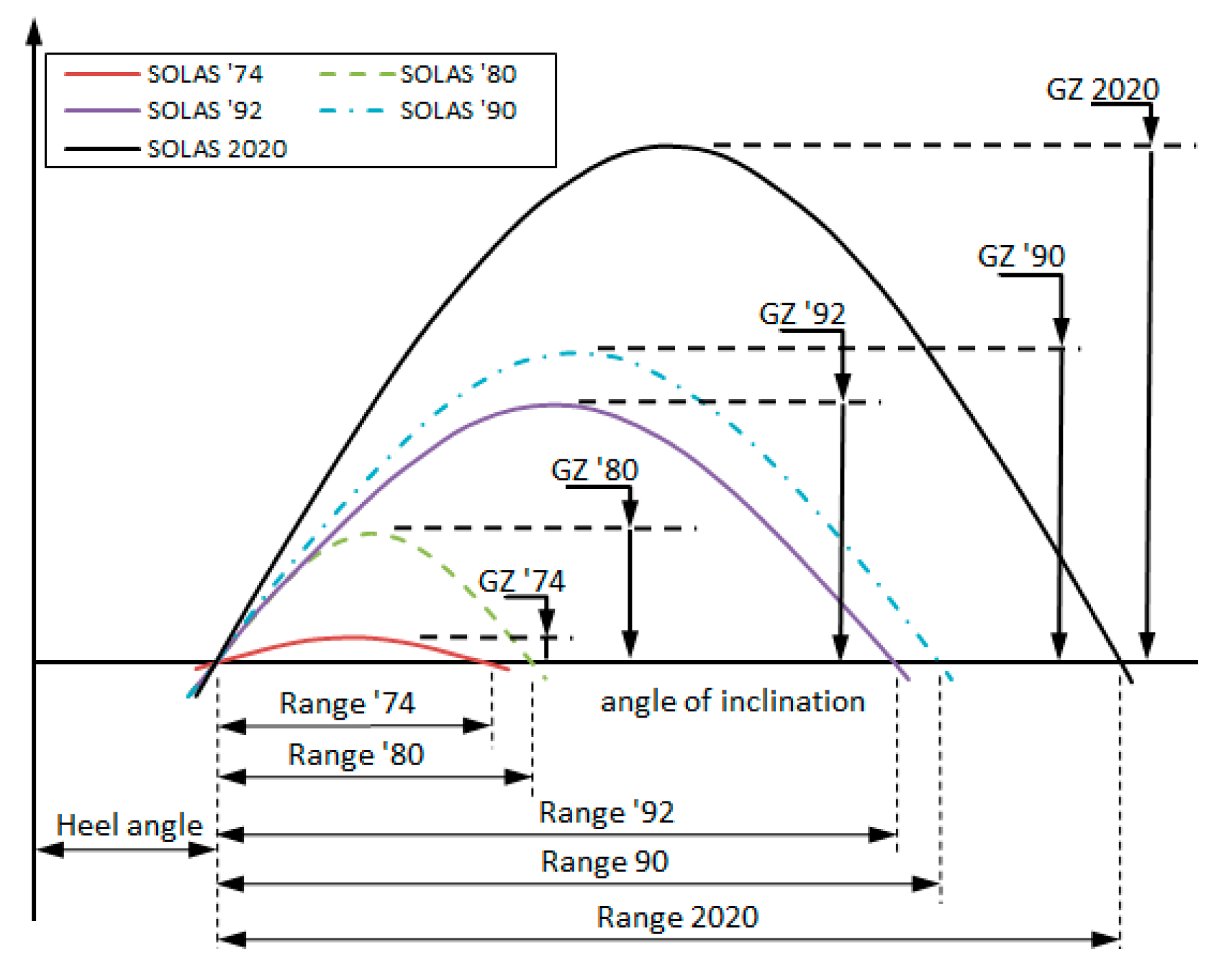
The fact of the matter is that whilst accidents with water on deck as the common loss mechanism have contributed to the evolutionary change of legislation, Figure 1, recurrence of such accidents clearly demonstrated that lessons learned did not go far enough. The Ro-Ro concept in RoPax ship designs is fundamental to the economic viability of such concepts, thus triggering a struggle in this evolution between safety of passengers and viability of business. Therefore, whilst large open spaces in RoPax vessels is an obvious design vulnerability to large scale flooding, reconfiguring this space to enhance safety is not obvious. Key reasons for this inertia include:
- (1)
- It will consume deck and hull space and affect ergonomy;
- (2)
- It will erode earning potential (cargo space, internal logistics, deadweight);
- (3)
- It will affect negatively loss of income.
4.2.2. Reconfiguration Going on Overdrive
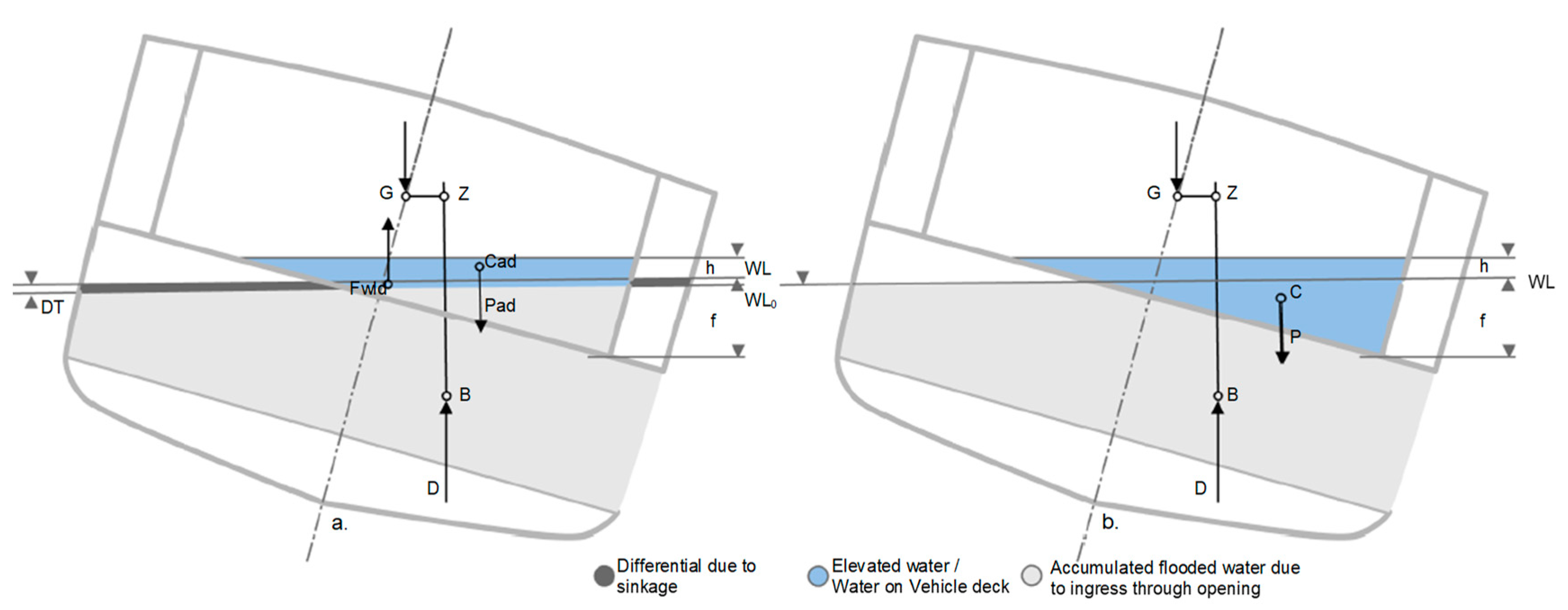
It has taken the largest modern day catastrophe, namely the Estonia disaster, claiming 853 lives, to shake the foundations of the industry and to bring economic and other barriers down, leading to a hull space reconfiguration onslaught, both external and internal to the ship hull, as summarized in Table 3 below pertaining to North West European Nations Ro-Ro fleet [52]. Research post-Estonia marks the first attempt to escape from the regulatory “trap” laid by Rahola and Bird, namely focusing on global design parameters. Describing their proposal of the static equivalent method [53], the main target was the reconfiguration of the Ro-Ro deck in RoPax ships, in addition to the traditional subdivision below the bulkhead deck, as shown in (2).
where both the and h are taken as median values of the respective random quantities. The critical significant wave height can be then used in the s-factor formulation adopting the cumulative distribution of waves from IMO. In project HARDER [30], the formulation was updated following a statistical relationship between dynamic water head (h), the freeboard (f), and the critical heel angle, and the mean significant survival wave height (Figure 2).
Observing the various risk control options used, the tendency for cluttering of the internal spaces becomes obvious, basically due to the fact that attention was focused around mid-ship, namely the middle 1/3 of the ship, as the Stockholm Agreement targeted SOLAS’90 2-compartment damages in this region. Notwithstanding this, the Stockholm Agreement was the first performance-based standard, accounting for water on deck and environmental conditions in the area of operation as well as the dynamic process of the vessel, the environment, and their interaction for the first time in maritime history.
It is noteworthy that no RoPax vessel has been lost since the introduction of this legislation due to water on deck problems. In fact, the Stockholm Agreement was in force in parallel with probabilistic regulations for damage stability, until it gave way to a fully probabilistic approach for RoPax vessels, namely SOLAS 2020, following a pertinent DGMOVE-funded study [44]. Part of this success is also owing to the fact that for the first time in the regulation history of damage stability, the Stockholm Agreement has been applied retrospectively. In the maritime industry, new legislation applies only to new buildings, thus leaving the majority of ships (90% of all the ships are already in operation) operating at inferior standards. This is known as the Grandfather’s Clause, a serious drawback in maritime safety and its evolution (Grandfather’s Clause is the legal term used to describe a situation in which an old rule continues to apply to some existing situations, while a new rule will apply to all future situations).
4.2.3. Making Sense of Reconfiguration
In project HARDER [30], tradition once again helped overrule deviation from convention and the physics-based formulation given in (2), leading to the formulation given in (3) for the survivability factor that formed the basis of SOLAS 2009 damage stability probabilistic rules, linking critical significant wave height (Hscrit) to parameters of the residual stability curve, namely GZmax and Range.
On the other hand, decluttering of internal reconfiguration through structural changes was significantly eased up with the introduction of the SOLAS 2009 probabilistic rules for damage stability as attention has been shifted from around the middle 1/3 of the ship and, in principle, below the ship hull to the whole ship, including penetration of damages up to the ship center line (instead of B/5) and up to 18 m from baseline, rather than up to the freeboard deck. However, being able to follow a rational approach to subdivision and flooding protection brought new problems of its own. Namely, with probabilistic damage stability rules having originally been developed on the basis of cargo ship damage statistics, serious concerns have been raised regarding the adopted formulation for the calculation of the survival probability of passenger ships and the associated required subdivision indices, particularly for RoPax and large cruise ships [36,39]. Due to disquiet in industry and academia and concern deriving from the escalation of passenger ships to megaships, research focus on damage stability has shifted towards large passenger ships and to a more holistic approach to flooding and fire incidents, known as “Safe Return to Port”.
4.2.4. A New Wave of Reconfiguration—Safe Return to Port
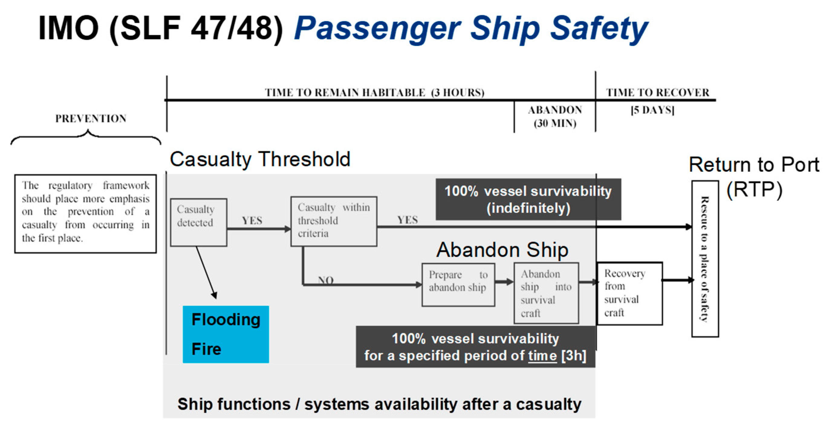
In May 2000, the IMO Secretary General called for a critical review of the safety of large passenger ships noting that “what merits due consideration is whether SOLAS requirements, several of which were drafted before some of these large ships were built, duly address all the safety aspects of their operation—in particular, in emergency situations”. This visionary prompt led the IMO Maritime Safety Committee (MSC) to adopt a new “philosophy” and a working approach for developing safety standards for passenger ships. In this approach, illustrated in Figure 3 (SLF 47/48), modern safety expectations are expressed as a set of specific safety goals and objectives, addressing design (prevention), operation (mitigation), and decision-making in emergency situations (emergency response) with an overarching safety goal, commensurate with no loss of human life due to ship-related accidents. This quest, in principle, a life-cycle risk management framework, has climaxed to the “zero tolerance” concept of safe return to port, introduced in July 2009 and the ensuing developments pertaining to “Safety Level”, “Alternative Design and Arrangements”, “Risk-Based Design”, and “Goal-Based Standards”. This prompted an open proclamation (April 2012) by the Secretary General of the International Maritime Organisation Koji Sekimizou, in addressing guests in the annual dinner of the royal institution of naval architects, of which deterministic requirements have no future. The term “Safe Return to Port” (SRtP) has been widely adopted in discussing this framework, which addresses all the basic elements pre-requisite to quantifying the safety level (life-cycle risk) of a ship at sea and providing an approach for de-risking all related fire and flooding casualties.
Casualty Threshold: This advocates the fact that the ship should be designed for improved survivability so that, in the event of a casualty, persons can stay safely on board as the ship proceeds to port. In this respect and for design purposes (only), a casualty threshold needs to be defined whereby a ship suffering a casualty below the defined threshold is expected to stay upright and afloat and be habitable for as long as necessary (it constitutes part of the design work to determine this value rationally, as it greatly influences the design arrangements (ship environment reconfiguration)) in order to return to port under its own power or wait for assistance. This, in turn, has introduced a new wave of internal ship space reconfiguration for protection of the ship prime movers with longitudinal B/10 bulkheads by way of the engine room as well as internal reconfiguration for redundancy provision by partitioning the engine room itself or other redundancy arrangements, involving segregation of essential systems.
Emergency Systems Availability/Evacuation and Rescue: Should the casualty threshold be exceeded, the ship must remain stable and afloat for sufficiently long time (3 h recommended) to allow safe and orderly evacuation (assembly, disembarkation, and abandoning) of passengers and crew. Emergency system availability to perform all requisite functions in any of the scenarios considered is, therefore, implicit in the framework. In addition, the ship should be crewed, equipped, and have arrangements in place to ensure the health, safety, medical care, and security of persons on-board in the area of operation, taking into account climatic conditions and the availability of SAR functions until more specialized assistance is available. This, in turn, introduced an array of changes in the internal ship environment as well as new spaces (safety areas) to enhance requisite functionality post-casualty, including: Safety centers, redundant safety systems, new evacuation routes, muster stations, new LSA; many of the latter within the internal ship envelop.
4.2.5. RoPax vs. Cruise Ships: Hitting a “Wall”
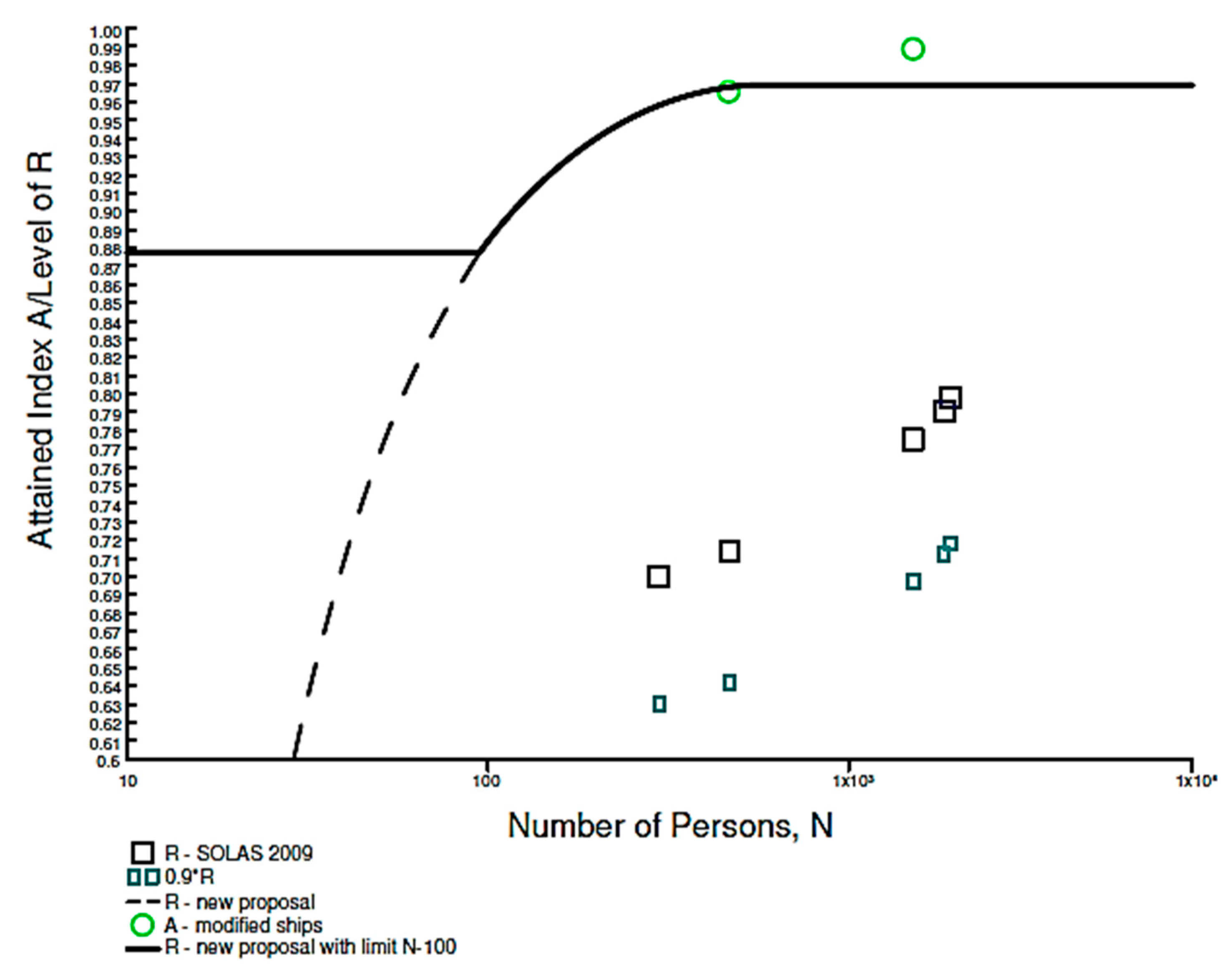
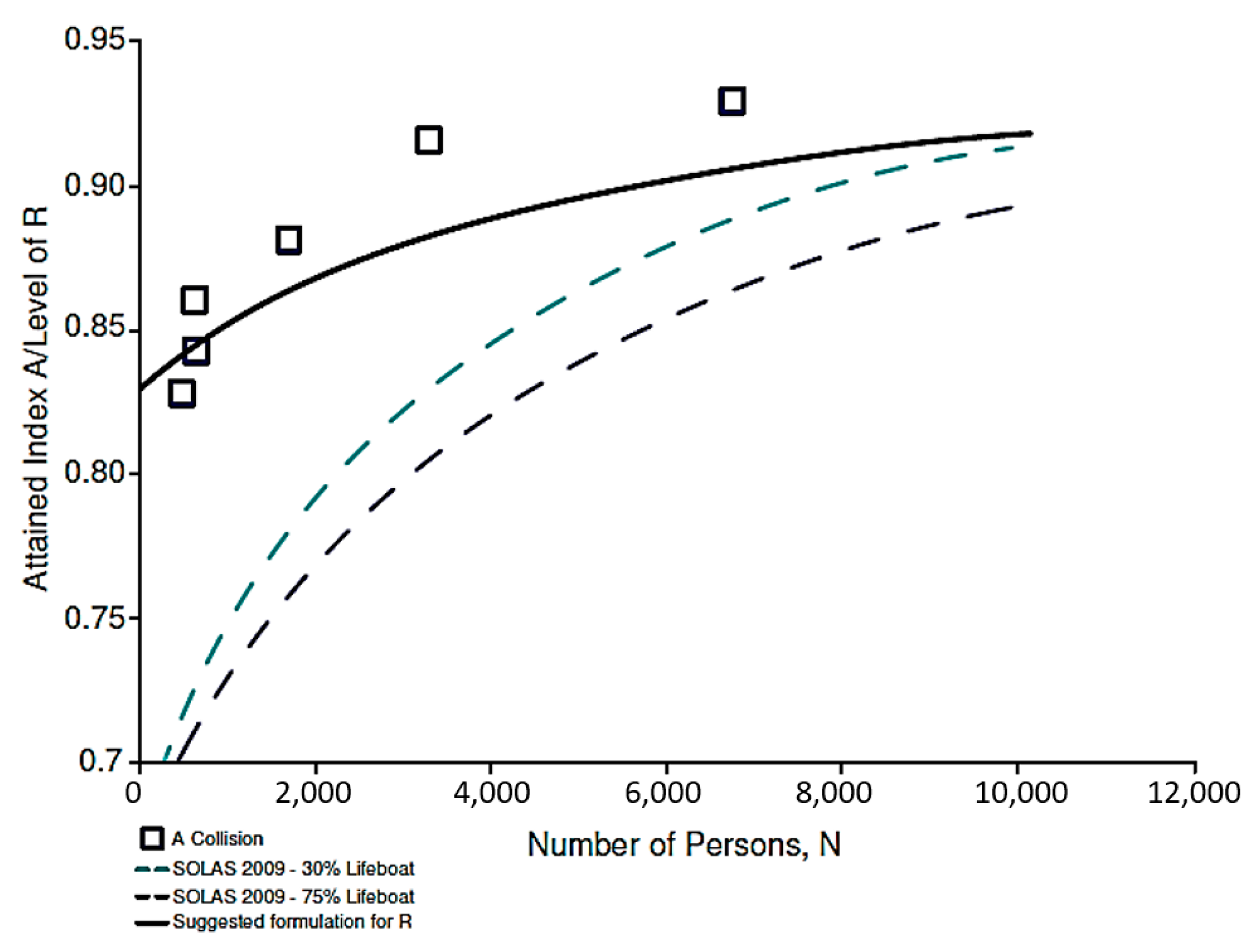
In support of the aforementioned developments and in the pursuit to de-risk large passenger ships, a series of projects investigated this problem and laid down the foundation for a passenger ship-specific damage stability framework, process, and criteria [40,41,42,43,44]. The outcomes of two of these projects are shown in Figure 4 and Figure 5.
Another outcome relates to alternative s-factor formulations accounting for the reconfiguration of the internal ship space, even above the strength deck, a real novelty, which for the first time was taken further in Project GOALDS [53,54].
where VR is a measure of the residual volume (scaled appropriately). The scene was set properly for this concept to be further considered in the project eSAFE where Atzampos has developed a formulation for the Hscrit [36].
where, TGZmax = 0.30 m target value for residual GZmax, TRange = 30 degrees target value for residual range, λ = scaling factor accounting for ship and damage size.
However, despite achieving better estimate of survivability, the fact that the general formulation failed to account for the complex internal environment of cruise ships, which undoubtedly determines the evolution of flooding and the eventual outcome, it was concluded that the only way forward in determining the damage survivability of cruise ships is by using the direct method of assessment, as explained in Section 5, which is also being adopted in EU-Project FLARE [45].
However, the strong suggestion by these research projects on increasing the damage stability standards, specifically for RoPax vessels and in general for passenger ships has met with strong resistance by industry, ultimately reaching a compromise at IMO for much modest damage stability standards. Key reasons for this relates to the industry having reached a conclusion that design measures to improve damage stability standards, primarily through further reconfiguration of the internal environment, has reached saturation and a crucial point where viability of business has to be compromised in favor of passenger safety. Something had to give and sacrificing the viability of the business will never be the route leading to a solution. Hence, the shift to a new perspective became inevitable.
4.2.6. Widening the Reconfiguration Perspective: Passive and Active Protection
The “necessity is the mother of all invention” dogma has one again offered a way forward. Namely, in the quest for damage stability improvement, design (passive) protection has traditionally been the only means to achieve this in a measurable/auditable way (SOLAS 2009, Ch. II-1). However, in principle, the consequences from inadequate damage stability can also be reduced by operational (active) measures, which may be very effective in reducing loss of life (the residual risk). There are two reasons for this. The first relates to the traditional understanding that operational measures safeguard against erosion of the design safety envelop (increase of residual risk over time). The second derives from lack of measurement and verification of the risk reduction potential by any active measures. In simple terms, what is needed is the means to account for risk reduction by operational (interventional) means as well as measures that may be taken during emergencies. Such risk reduction may then be considered alongside risk reduction deriving from design measures. Therefore, new measures for risk reduction (operational and in emergencies) should be considered in addition to design measures. What needs to be demonstrated and justified is the level of risk reduction and a way to account for it, the latter by adopting a formal process and taking requisite steps to institutionalize it. Efforts in this direction is the focus of ongoing large-scale EC-funded research project, FLARE [45]. The key facilitator in this respect is the regulation for Alternative Design and Arrangements (AD&A) [55,56], which opens the door to innovation.
5. The Way forward: Technological Innovation Is the Key
Notwithstanding the lack of a life-cycle regulatory framework complete with passive and active measures of damage stability protection, the regulation for “alternatives” provides the requisite platform for the first important steps. As indicated in the foregoing, with accidents providing the main motivation, emphasis has primarily been placed on reducing consequences, i.e., on cure rather than prevention. The key reason for this derives from the fact that the residual risk post flooding accidents is unacceptably high, meaning that the most-cost-effective way to reducing flooding risk is to reduce the residual risk, namely on technological innovation, targeting cost-effective solutions to damage stability problem.
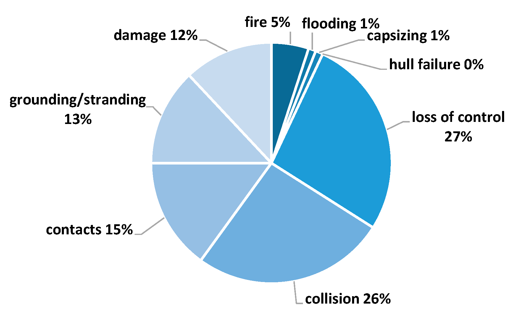
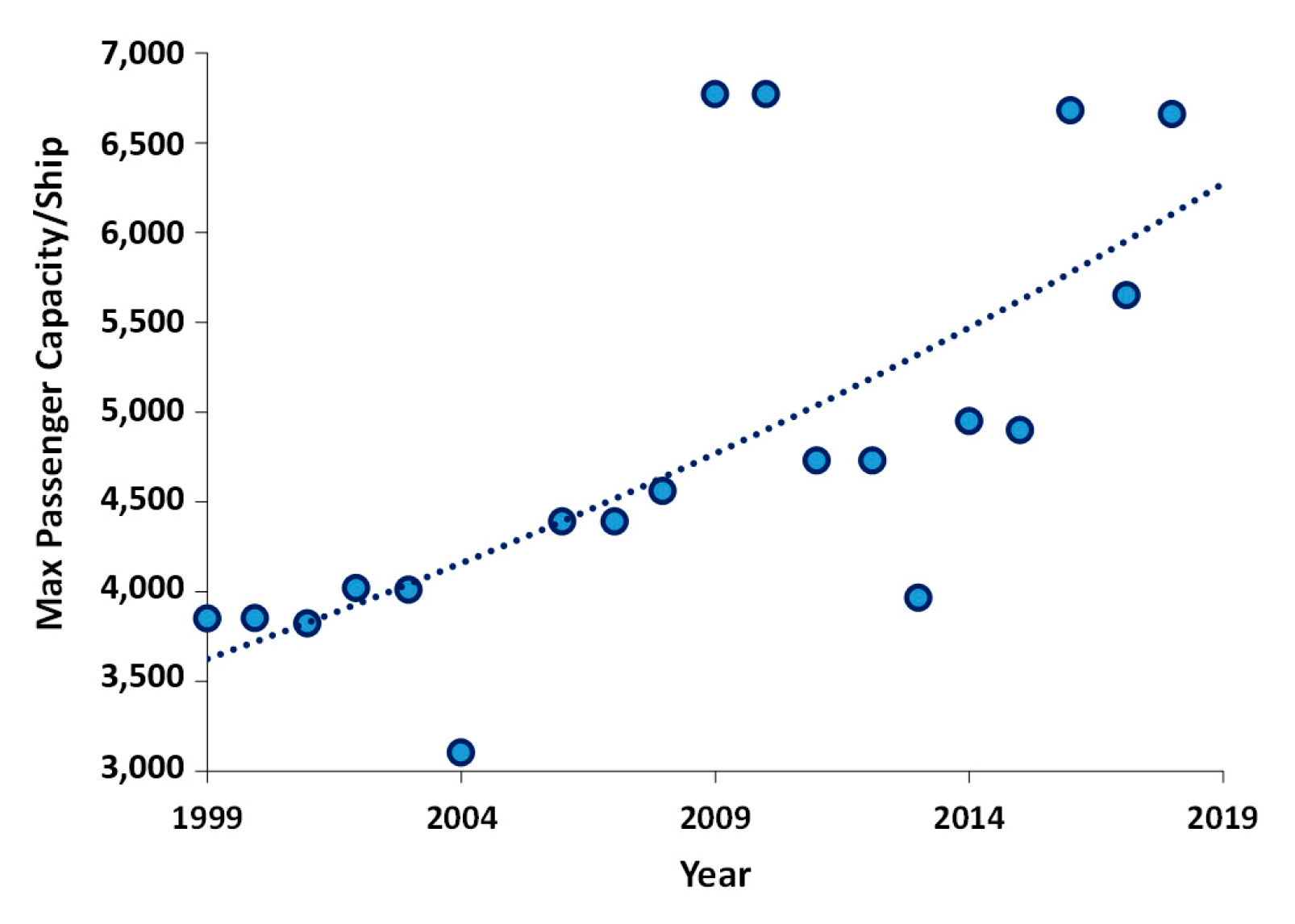
5.1. Damage Stability Is Still the Highest Risk Contributor in the Maritime Industry
Within half a century, progress in damage stability research and application has been unprecedented, from a subject barely understood and largely unscientific to considering real-time flooding risk assessment on-board. Moreover, the divide between research and application has been narrowing over the years, with an array of safety systems and emergency response systems on-board some of the modern passenger ships that can challenge any other transport industry. This has put ship safety in perspective and with flooding post collision and grounding accidents continuing to be the key risk contributor for passenger ships, resolving this problem remains a priority (Figure 6). In particular, for cruise ships, Figure 7 shows that the maximum numbers of passengers carried by the largest cruise ships each year has risen dramatically, almost doubling to 6800 in 2019 compared to 1999 (Clarkson, 2020). This means that there is now a far greater risk of passenger fatality from any given single accident.
Moreover, the realization that risk is inextricably linked to operation and a derivative of exposure has driven the industry to life-cycle considerations for effective risk management. This, in turn, has provided the motivation and the platform for wider industry inculcation.
5.2. Adaptive Reconfigurable Environment Safety Technology (AREST) Systems
5.2.1. The Concept
Safety is normally a compromise to vessel earning potential and, as public demand for higher safety standards grows, industry is forced to choose between viability of business and safety of customers. To address this for flooding risk the “in-operation” optimal internal arrangement of the vessel is adapted and reconfigured, using passive (in-built) and active (controlled) containment systems, comprising the use of high expansion foam to restrict and contain the amount of floodwater entering the ship hull post flooding accidents, to provide the most effective protection possible, when in crisis from any flooding events [57]. With passive/active foam protection, flooding risk is all but eradicated. This leads to transformational reduction in flooding risk in the most cost-effective way available.
5.2.2. Loss Modalities of a Damaged Ship
To contain and control the outcome of a ship hull breach in the event of collision and grounding accidents, particularly in ships with complex internal architecture, such as passenger ships, it is important to be able to understand and assess quickly whether the ship will survive the damage or not and in the latter case, how long it will take. In either case, it will be prudent to have all this knowledge a priori (e.g., during the design phase by exploring all feasible damage cases, identifying loss scenarios, and taking measures to either contain and control all such scenarios or allow for safe evacuation of all the people on-board). This, in turn, entails understanding of loss modalities and a forensic detail of floodwater progression. A brief explanation of the former is warranted here to allow for an educated introduction of the various flooding risk control options being introduced in the next section.
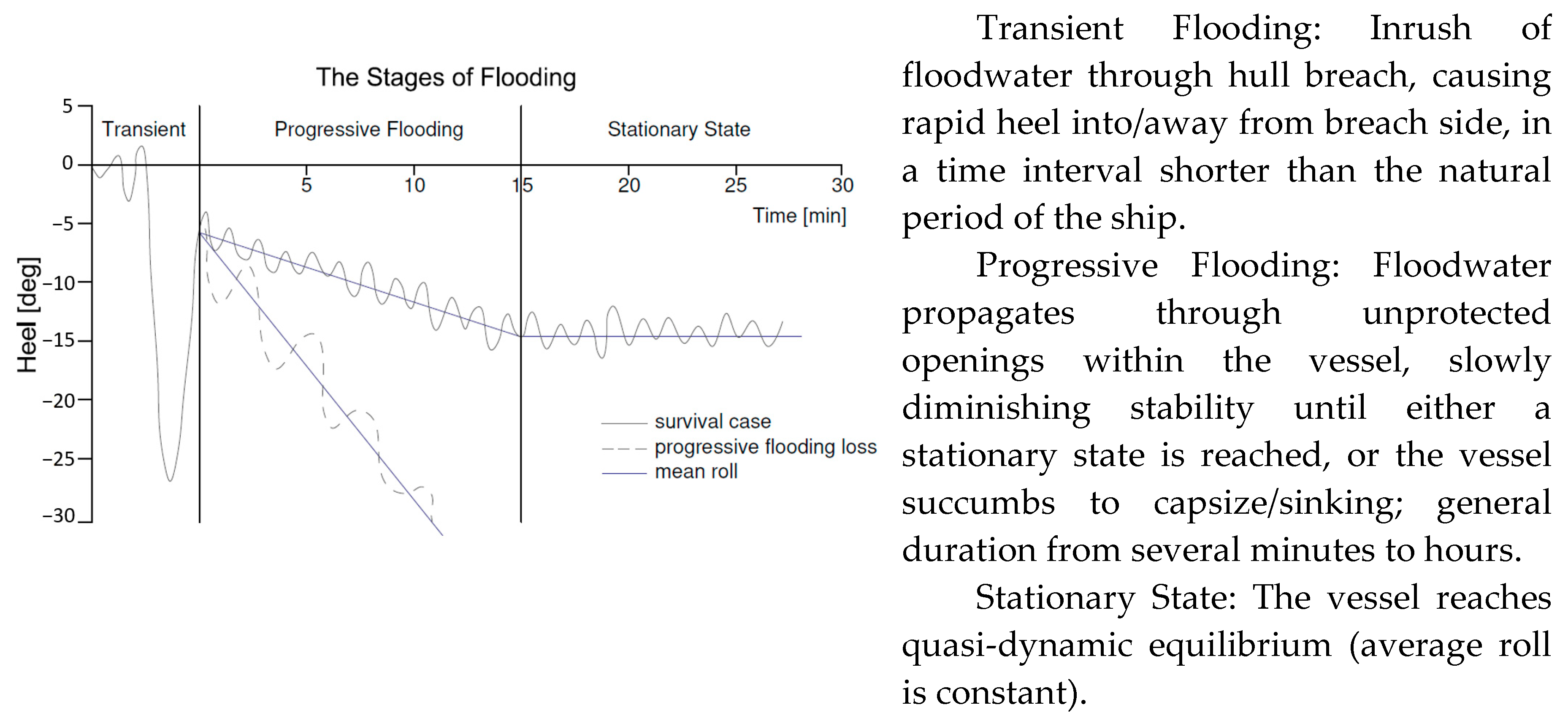
Following hull breach of a ship in a seaway that leads to flooding of internal ship spaces, the ship will first undergo a transient response as a result of the inrush of floodwater, which may lead to the vessel capsizing without equilibrium being restored (transient asymmetric flooding), such response resulting normally with the ship heeling towards the oncoming waves, but depending on the latter and the ship response, the ship may heel towards the leeside, which, depending on the size of the breach and the internal ship arrangement, may be beneficial. As a general conclusion, the multitude of parameters affecting the initial response and the evolution of flooding and ship behavior means that one cannot address these prescriptively. Here a generalized description is presented in Figure 8 to facilitate better understanding of the risk control options being advocated.
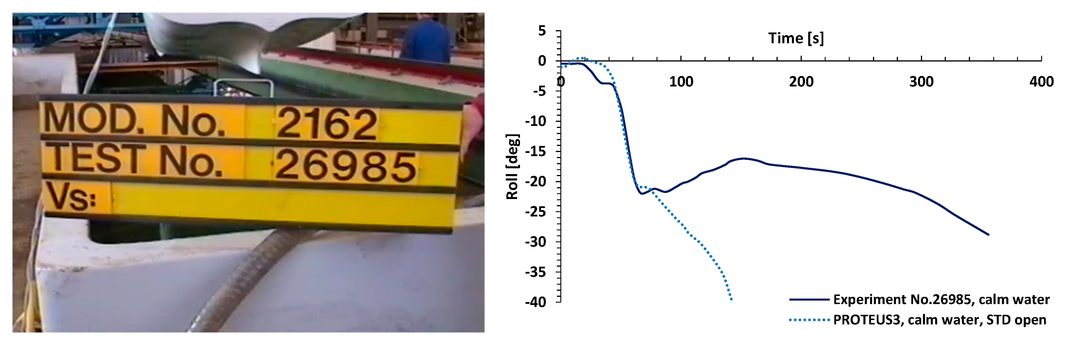
The first reported transient capsize was for European Gateway [59]. For cruise ships, the transient capsize phenomenon was first noticed and studied in [58,60] but the observations and derived results did not make any significant inroads into the regulation-making process. This is rather unfortunate, as time limitations, relating to transient flooding loss, render this the most dangerous loss mode. Some attempts have been made to consider the effect of transient flooding on stability by focusing on different stages of this process in a quasi-static manner and, in this respect, an intermediate stage s-factor has been adopted at IMO (SOLAS 2009 Regulations). Figure 9, relating to a large-scale model experiment and to numerical simulation results of the same, demonstrate that transient capsize of a typical cruise ship 2-compartment SOLAS damage could take place rather quickly for a ship in full compliance with statutory damage stability regulations [58].
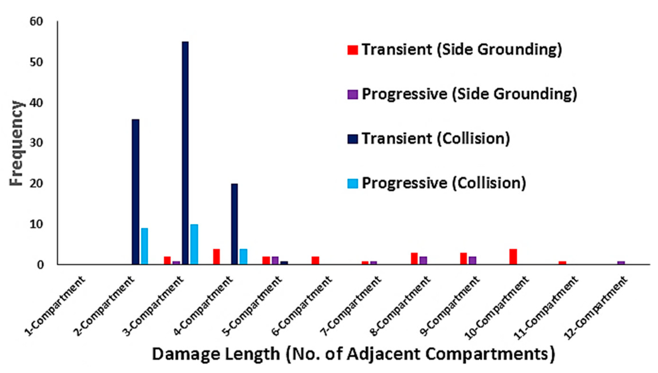
Similarly, Figure 10, where time-domain simulation software for damage survivability in waves is used to identify different loss modalities, demonstrates that transient capsizes for 2-compartment damages of a very good SOLAS’90 cruise ship design is quite common.
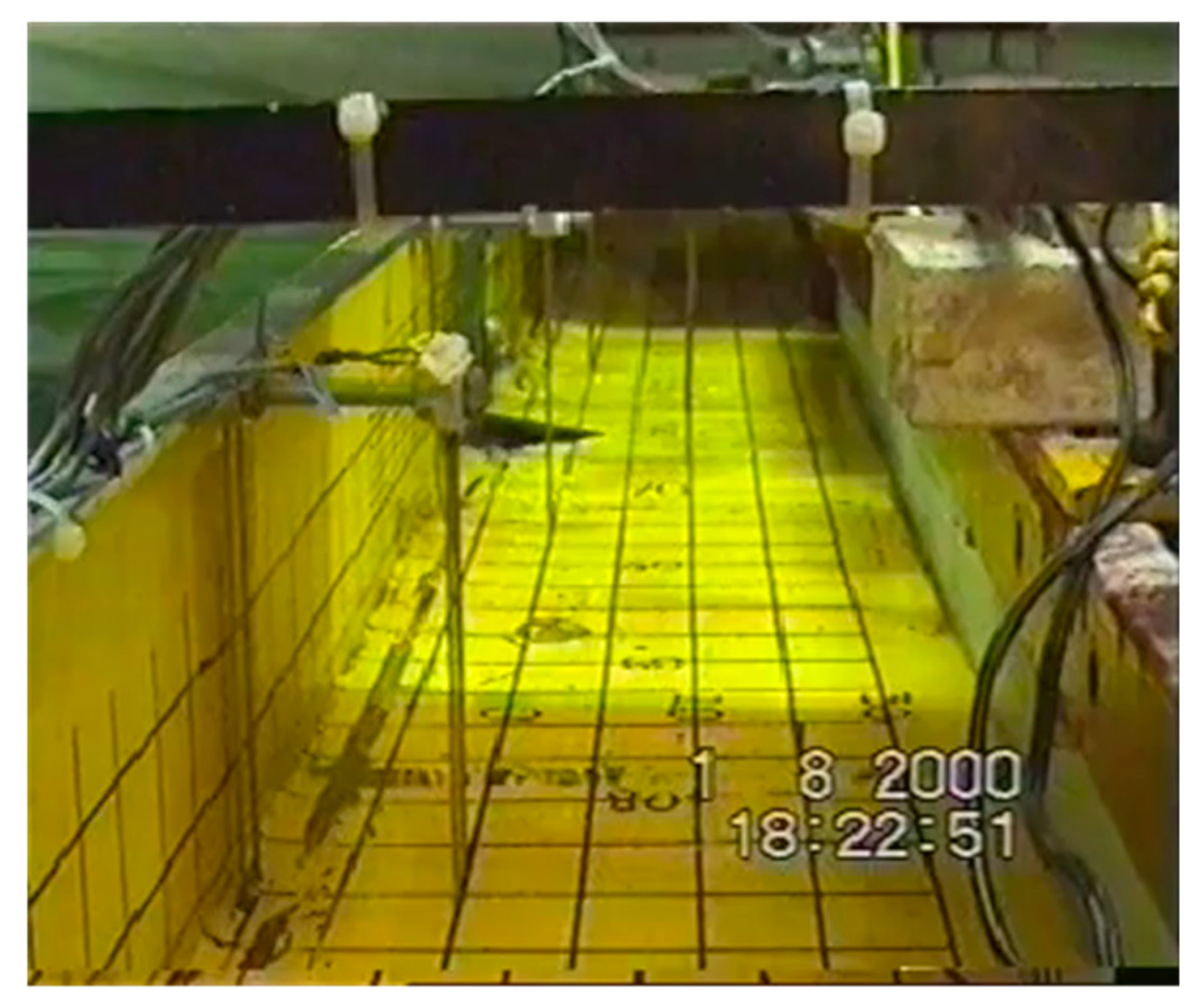
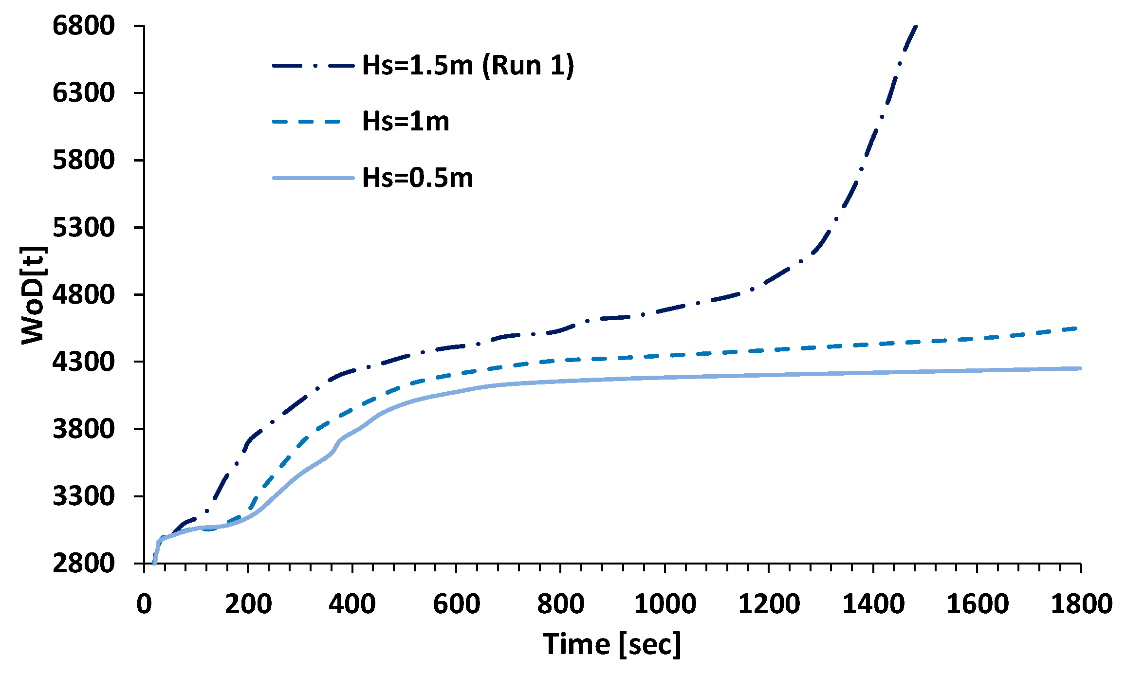
Progressive flooding capsizes have been studied more systematically in the various EC-funded and other projects and have been made the basis for the current SOLAS (SOLAS 2009 and SOLAS 2020) requirements. However, even in these regulations, this loss modality is considered on the basis of mainly experimental results of RoPax vessels in waves up to 4 m Hs with the effect of the latter considered as an average influence on survivability, captured by correlating GZ-curve properties (GZmax and Range) to Hs, as explained earlier. Typical RoPax vessel test set up and results in progressive flooding loss modality are shown in Figure 11 and Figure 12, respectively. This is a mode of capsize that was made the basis for all contemporary developments, particularly pertaining to probabilistic regulations, adopted at IMO. The rapidly escalating trace of water on deck in Figure 11 designates the time instant, which is normally referred to in the literature as the “point of no return”, at which the mass of floodwater on the car deck increases exponentially and the vessel capsizes very rapidly. Of course, in the presence of superstructure, this may delay considerably as in the case of the RoPax vessel Estonia where it has taken 50 min for the vessel to “turn turtle” and eventually sink. Moreover, water accumulation on the car deck is not entirely deterministic as it depends on many stochastic influences; hence, it is rather difficult to estimate the amount of water on deck, leading to vessel capsize. In cruise ships, a similar mechanism may lead to vessel loss, in this case related to the service corridor on the main deck, which provides the conduit for water to spread longitudinally in the vessel as well as up-flooding via the vertical service trunks and stairwells.
5.2.3. Reconfiguration by AREST Systems
AREST Systems relate to a University of Strathclyde Patent (Patent No.PCT/GB2017/050681) pertaining to a series of active and passive patented systems, comprising the use of high expansion foam to restrict and contain the floodwater entering the hull post flooding accidents. The deployable systems also offer fire protection as per SOLAS. An illustration and brief description for the various systems is provided in the following.
AREST P1: Crashworthy Vulnerable Areas with Permanent Void Foam Filling
The AREST P1 system focuses on vulnerable areas where improved structural crashworthiness (favorable redistribution of the p-factor/reduction of the crash probability, Figure 13) will lead to improved survivability. This is a design (passive) measure, independent of loss modality. The crashworthy structural design alternative that is being considered is the addition of a longitudinal B/10 bulkhead (covering only the vulnerable area extent) with the void in between filled with high expansion foam. Risk reduction (improved survivability) and cost of this risk control option will support a cost-effectiveness analysis using gross cost of averting a fatality (GCAF) for ship survivability enhancement. Approval through the alternative design and arrangements (AD&A) process is required. Improvement on survivability is significant (depending on the protected area) and this is further enhanced by filling the void with high expansion foam to reduce asymmetry and to further enhance crashworthiness [61].
AREST P2: Passive Foam Installation—Permanent Void Filling
This is a passive flooding protection system pertaining to the installation of permanent foam in void spaces, see Figure 14, to provide additional reserve buoyancy when these spaces are damaged following a flooding incident, thus increasing GM. Such installations act much like buoyancy tanks with impermeable volume to provide buoyancy when damaged within the immediate damaged area. Upon installation, the foam adheres to the vessel steel structure and acts as a protective/anti-corrosive coating, prohibiting build-up of moisture between foam and the ship structure, offering effective insulation. The foam is resilient and will last, without degradation, for the vessel’s life span.
AREST A1: Active Foam Application—Filling Voids in Flooded Compartments
This is an active foam deployment system comprising modular, standard “kit of parts” in the form of bottled foaming agents, dedicated pump and piping system, and centralized distribution as may be requited. It is located in a non-intrusive location within the vessel and is fully integrated into the ship safety management system with dedicated decision support. Foam is deployed in high-risk ship compartments on top of the floodwater entering the ship to suppress, contain, and control its progression and potentially to push floodwater out, see Figure 15. This results in a reduction in lost buoyancy, free surface effects and progressive flooding, thus leading to enhanced damage stability. The foam being used is closed cell with 1–2% permeability, 1:40 expansion ratio, 1 bar expanding pressure, and 2 bar compressive strength.
AREST A3/A3F: Deployable Watertight Bulkheads for Flooding/Fire Protection
During the flooding process of a complex internal environment, like that of a modern cruise ship, the progressive flooding paths therein can be likened to the cardiovascular system of the human anatomy. Thus, there exist minor progressive flooding paths, acting like veins and major progressive floodwater paths like arteries. In order to most effectively deal with progressive flooding, it is best to focus on blocking these arteries (Figure 16). In this schematic representation of a complex internal ship environment, it can be observed that although the progressive flooding process can take on a multitude of routes through many openings, if it is simply cut off at its source, the problem can be dealt with in a simple, yet highly effective manner. This is facilitated through forensic examination of all flooding scenarios to identify critical openings and flooding pathways.
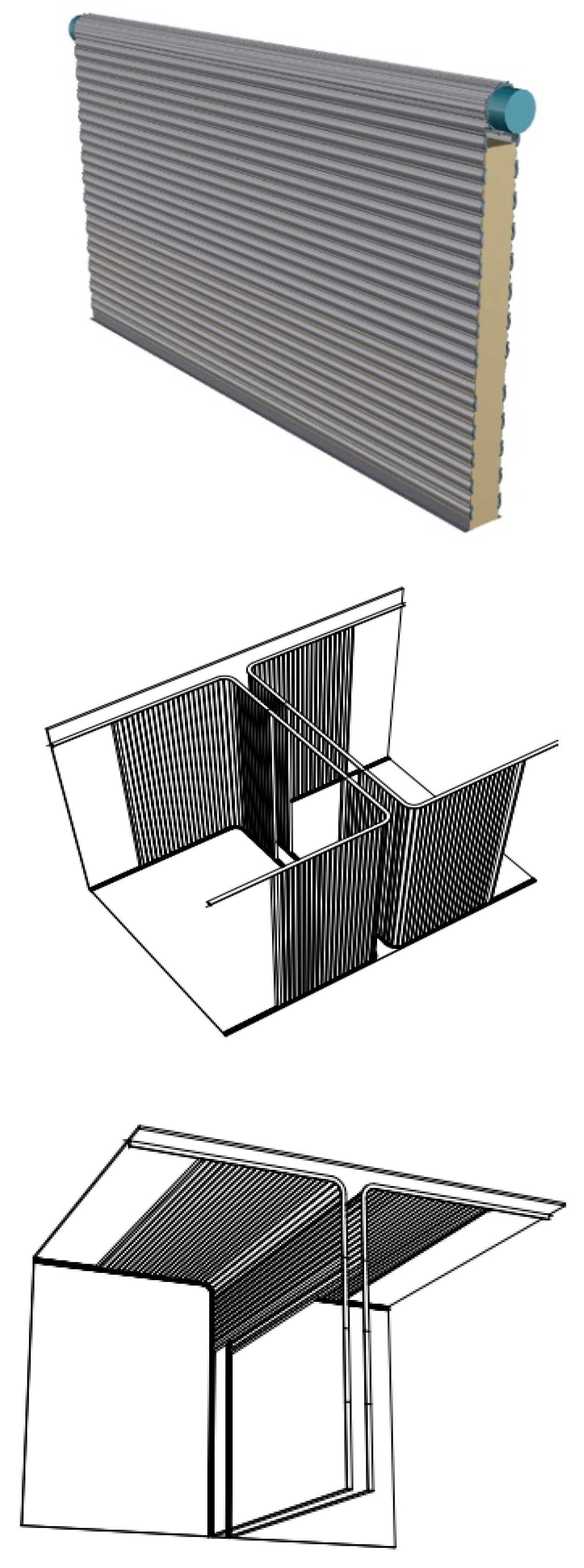
Deployable barriers comprise two lightweight shutters made of fire-resistant flexible textile, 30 cm thick (normally A-class fire rated). Shutters are only deployed in case of fire casualties. In the case of flooding, the cavity between shutters is filled with expanding foam delivered from a compressed foam canister. As demonstrated in the schematic arrangements in Figure 17, the shutters are mechanically operated to be deployed vertically or horizontally to suit local structural details and arrangements. The watertight integrity ascertained is typically rated up to 2 bar (20 m water head). The barrier can span distances up to 30 m, with stiffening rods present within the textile, and can be deployed within minutes to curtail and control previously identified critical floodwater pathways. In this respect, drawing on the results of the time-domain flooding simulations, an effective damage control plan could be set up and suitably executed with the aid, for example, of a purposely-developed decision support system linked to the ship safety management system. This process can be guided in the most effective way, thus providing the vessel damage response team with the ability to actively suppress floodwater propagation by isolating the damage area following any foreseeable critical flooding event where progressive flooding is responsible for loss. This offers a distinct advantage over existing damage control plans, which are limited in that they rely entirely on fixed design measures in order to contain the spread of floodwater. As such, they have limited flexibility and cannot effectively deal with all probable loss scenarios. In addition, there are a number of areas within any vessel in which watertight integrity must be sacrificed in order to allow for effective operation of the vessel, i.e., lift trunks, service corridors, non-watertight doors.
6. Concluding Remarks
Deriving from the work described in the foregoing, the following concluding remarks may be drawn:
- (1)
- The internal environment of a passenger ship is complex and the bigger and more modern the ship is, the more complex the internal environment becomes. There are many reasons for this relating to functionality (hotel, entertainment), performance (flow of people and goods), and cost (construction and maintenance). On the other hand, structural strength and reliability, as well as the basic need for structures to be crashworthy, add more constraints, on top of those pertaining to safety, leading to a complex design optimization problem and to compromise. Given this, and despite many claims in the literature that in this array of competing objectives safety is more often than not compromised, this paper clearly demonstrates that safety has had the biggest influence in shaping the reconfiguration of the internal environment;
- (2)
- However, the aforementioned influence has not always been rational or timely, mostly a reaction to disasters with focus on damage limitation and passive protection in ways that more often than not lacks rationale and justification;
- (3)
- Having said this, safety enhancement, despite the slow evolutionary process being followed, has been impressive and continuous and, insofar as new build passenger ships are concerned, one may say remarkable;
- (4)
- However, existing ships, which represent the majority of ships in service have been compromised through a regulatory anomaly (Grandfather’s Clause), thus putting at unwarranted risk the majority of the traveling public. Lack of knowledge and technological know-how to address this problem lead to it being quietly ignored;
- (5)
- This need not be the case any longer. Technological innovation and a knowledge fund built on this facilitate the development of tools, processes, safety products, and frameworks that would enable all-embracing and rational approaches to safety and to reconfiguration of the internal ship environment to raise safety standards to the level modern society expects and demands.
Funding
This research received no external funding.
Conflicts of Interest
authors declare no conflict of interest.
References
- Heath, T.L. The Works of Archimedes; Dover Publications, Inc.: Mineola, NY, USA, 2002. [Google Scholar]
- Nowacki, H. Leonard Euler and the Theory of Ships. J. Ship Res. 2007, 52, 274–290. [Google Scholar]
- King, J. Origins of the Theory of Ship Stability; The Royal Institution of Naval Architects: London, UK, 1998. [Google Scholar]
- Hoste, P. Théorie de la Construction des Vaisseaux (Theory of Ship Constructio); Arisson & Posule: Lyon, France, 1697. [Google Scholar]
- Bouguer, P. Traité du Navire, de sa Construction et de ses Mouvemens; Jombert: Paris, France, 1746. [Google Scholar]
- Euler, L. Scientia Navalis, seu Tractatus de Construendis ac Dirigendis Navibus pars prior Complectens Theoriam Universam de Situ ac motu Corporum Aquae Innatantium; Typis Academiae Scientiarum: St. Petersburg, Russia, 1749; Volume 1. [Google Scholar]
- Atwood, G.; de Clairbois, M.V. A Disquisition on the Stability of Ships; By George Atwood, Esq. F. R. S.; Philosophical Transactions of the Royal Society of London: London, UK, 1798; Volume 88, pp. 6–310. [Google Scholar]
- Vassalos, D. Shaping ship safety: The face of the future. J. Mar. Technol. 1999, 36, 61–74. [Google Scholar]
- Rahola, J. The Judging of the Stability of Ships and the Determination of the Minimum Amount of Stability. Ph.D. Thesis, The University of Finland, Helsinki, Finland, May 1939. [Google Scholar]
- Womack, J. Small Commercial Fishing Vessel Stability Analysis Where Are We Now? Where Are We Going? In Proceedings of the 6th International Ship Stability Workshop, New York, NY, USA, 13–16 October 2002. [Google Scholar]
- MSC 82/24/Add.1. In Proceedings of the Adoption of amendments to the International Convention for the safety of life at sea, 1974, Resolution MSC 216 (82), adopted on 8th December 2006. Available online: https://www.google.com.hk/url?sa=t&rct=j&q=&esrc=s&source=web&cd=&cad=rja&uact=8&ved=2ahUKEwiIyoj1-dXrAhUUzIsBHXR4D58QFjACegQIBRAB&url=http%3A%2F%2Fwww.jsmqa.or.jp%2FNotice%2FLifeboat%2FMSC.216(82).pdf&usg=AOvVaw1NgRsZDDl10bikZHQSlCpj (accessed on 6 September 2020).
- Tagg, R.; Tuzcu, C. A Performance-based Assessment of the Survival of Damaged Ships—Final Outcome of the EU Research Project HARDER. In Proceedings of the 6th International Ship Stability Workshop, New York, NY, USA, 8–10 June 2002. [Google Scholar]
- Wendel, K. Die Wahrscheinlichkeit des Uberstehens von Verletzungen. Schiffstechnik 1960, 7, 47–61. [Google Scholar]
- Wendel, K. Subdivision of Ships. In Proceedings of the 1968 Diamond Jubilee International Meeting—75th Anniversary; paper No 12; SNAME: New York, NY, USA, 1968; p. 27. [Google Scholar]
- Vassalos, D. Risk-Based Ship Design. In Risk-Based Ship Design—Methods, Tools and Applications; Papanikolaou, A., Ed.; Springer: Berlin/Heidelberg, Germany, 2008; Chapter 2; pp. 17–98. ISBN 978-3-540-89042-6. [Google Scholar]
- Vassalos, D. Design for Safety, Risk-Based Design, Life-Cycle Risk Management, Keynote Address. In Proceedings of the International Marine Design Conference, Glasgow, UK, 11–14 June 2012. [Google Scholar]
- Gale, P. Ship Design and Construction T. Lamb; SNAME: New York, NY, USA, 2003; Chapter 5. [Google Scholar]
- Klanac, A. Design Methods for Safe Ship Structures. Ph.D. Thesis, Aalto University, Espoo, Finland, 2011. [Google Scholar]
- Klanac, A.; Ehlers, S.; Tabri, K.; Rudan, S.; Broekhuijsen, J. Qualitative Design Assessment of Crashworthy Structures; Int Maritime Association of Mediterranean: Lisbon, Portugal, 2005; pp. 461–469. [Google Scholar]
- Misra, S.C. Design Principles of Ship and Marine Structures; CRC Press: Boca Raton, FL, USA; Taylor and Francis Group: Abingdon, UK, 2016. [Google Scholar]
- Paik, J.K. Computational Models for Structural Crashworthiness Analysis in Collisions and Grounding. In Advanced Structural Safety Studies; Springer: Berlin/Heidelberg, Germany, 2020; pp. 279–311. [Google Scholar]
- Vassalos, D.; Papanikolaou, A. A holistic view of Design for Safety. In Proceedings of the 7th International maritime Safety Conference on Design for Safety, Kobe, Japan, 16–21 September 2018. [Google Scholar]
- Puisa, R.; Murphy, A.; Khaled, A.; Vassalos, D. Design Customisation and Optimisation through Effective Design Space Exploration; IMDC: Glasgow, UK, 2012. [Google Scholar]
- [SAFEDOR (2005-2009)]. Design, Operation and Regulation for Safety, Integrated Project, FP6_2 Contract TIP4-CT-2005-516278. Available online: www.safedor.org (accessed on 17 June 2020).
- Vassalos, D.; Turan, O. Development of Survival Criteria for Ro-Ro Passenger Ships—A Theoretical Approach. In Final Report on the S0T Ro-Ro Damage Stability Programme; University of Strathclyde: Glasgow, UK, 1992. [Google Scholar]
- Vassalos, D.; Turan, O. A Realistic Approach to Assessing the Damage Survivability of Passenger Ships; SNAME: New York, NY, USA, 1994. [Google Scholar]
- Vassalos, D.; Letizia, L. Formulation of a Non-Linear Mathematical Model for a Damaged Ship Subject to Flooding; Sevastianov Symposium: Kaliningrad, Russia, 1995. [Google Scholar]
- De Kat, J. Dynamics of a ship with partially flooded compartment. In Proceedings of the 2nd Workshop on Stability and Operational Safety of Ships, Osaka, Japan, 18–19 November 1996. [Google Scholar]
- Zaraphonitis, G.; Papanikolaou, A.; Spanos, D. On a 3D Mathematical Model of the Damage Stability of Ships in Waves. In Proceedings of the 6th International Conference on Stability of Ships and Ocean Vehicles, Varna, Bulgaria, 22–27 September 1997. [Google Scholar]
- HARDER. Harmonisation of Rules and Design Rationale; EC Contact No. GDRB-CT-1998-00028, Final Technical Report; IMO Publishing: London, UK, 2003. [Google Scholar]
- Letizia, L.; Besse, P. First-Principles Design for Damage Resistance against Capsize; EC Project CONTRACT No. G3RD-CT 1999-00029; EC: Brussels, Belgium, 1999. [Google Scholar]
- Probabilistic Rules-Based Optimal Design for Ro-Ro Passenger Ships; EU FP5 RTD Project G3RD-CT-2000-00030; ROROPROB (1999–2002). Available online: https://trimis.ec.europa.eu/project/probabilistic-rules-based-optimal-design-ro-ro-passenger-ships#tab-partners (accessed on 6 September 2020).
- Jasionowski, A. Survival Criteria for Large Passenger Ships; SAFENVSHIP Project, Final Report; Safety at Sea Ltd.: Glasgow UK, 2005. [Google Scholar]
- Jasionowski, A.; Vassalos, D. Benchmark Study on the Capsizing of a Damaged Ro-Ro Passenger Ship in Waves; Final Report to the ITTC Specialist Committee on the Prediction of Extreme Motions & Capsizing; 2001. Available online: https://www.google.com.hk/url?sa=t&rct=j&q=&esrc=s&source=web&cd=&cad=rja&uact=8&ved=2ahUKEwimgMS199PrAhXLZt4KHTqEBh8QFjABegQIARAB&url=http%3A%2F%2Fold.naval.ntua.gr%2Fsdl%2FITTC%2FAbout%2FITTC%2520Study%2520-%2520Report%2520-%2520Dec2001.pdf&usg=AOvVaw0-PPBgcaLR6g6-YDsVTn1A (accessed on 6 September 2020).
- Vassalos, D.; York, A.; Jasionowski, A.; Kanerva, M.; Scott, A. Harmonised Damage Stability Regulations; STAB: Rio de Janeiro, Brazil, 2006. [Google Scholar]
- Atzampos, G. A Holistic Approach to Damage Survivability Assessment of Large Passenger Ships. Ph.D. Thesis, University of Strathclyde, Glasgow, UK, 2019. [Google Scholar]
- Vassalos, D.; Jasionowski, A.; York, A.; Tsakalakis, N. SOLAS ’90, Stockholm Agreement, SOLAS 2009—The False Theory of Oranges and Lemons. In Proceedings of the 10th International Stability Workshop, Daejeon, Korea, 23–25 March 2008. [Google Scholar]
- Vassalos, D.; Jasionowski, A. SOLAS 2009—Raising the Alarm. In Contemporary Ideas on Ship Stability and Capsizing in Waves; Neves, M., Ed.; Springer: Berlin/Heidelberg, Germany, 2011; Chapter 6. [Google Scholar]
- Vassalos, D. Damage Survivability of Cruise Ships—Evidence and Conjecture. Ocean Eng. 2016, 121, 89–978. [Google Scholar] [CrossRef]
- Papanikolaou, A.; Hamann, R.; Lee, B.S.; Lemoine, L.; Mains, C.; Olufsen, O.; Tvedt, E.; Vassalos, D.; Zaraphonitis, G. GOALDS: Goal-Based Damage Stability of Passenger Ships; SNAME: New York, NY, USA, 2013. [Google Scholar]
- EMSA. A Study to Assess Acceptable and Practicable Risk Levels for Damage Stability of Passenger Ships; EMSA: Lisbon, Portugal, 2013–2015. [Google Scholar]
- EMSA. Study of the Specific Damage Stability Parameters of Ro-Ro Passenger Vessels according to SOLAS 2009, including Water on Deck Calculation; Ship Stability Research Centre: Glasgow, UK, 2011. [Google Scholar]
- eSAFE. Damage Stability of Cruise Ships; Joint Industry Project; Cruise Ship Safety Forum: 2017–2019. Available online: https://www.google.com.hk/url?sa=t&rct=j&q=&esrc=s&source=web&cd=&cad=rja&uact=8&ved=2ahUKEwiXrpbD-9XrAhXHc94KHZ82CC4QFjAAegQIBRAB&url=http%3A%2F%2Fwww.shipstab.org%2Ffiles%2FProceedings%2FISSW%2FISSW_2019_Helsinki_Finland%2FPapers%2F7_0_Luhmann_ISSW2019.pdf&usg=AOvVaw2vaPE7xWjn4JuLJkMPIU9S (accessed on 6 September 2020).
- DGMOVE. Assessment of Specific EU Stability Requirements for Ro-Ro Passenger Ships; EU: Brussels, Belgium, 2019. [Google Scholar]
- FLARE, EU H2020—MG2.2 (2019–2022): Flooding Accident Response. Available online: https://cordis.europa.eu/project/id/814753 (accessed on 6 September 2020).
- Lancaster, J. Engineering Catastrophes: Causes and Effects of Major Accidents; Abington Publishing: Abington, PA, USA, 1996. [Google Scholar]
- Spouge, J. The Safety of Ro-Ro Passenger Ferries; RINA: Genoa, Italy, 1989. [Google Scholar]
- Svensen, T.E.; Vassalos, D. Safety of Passenger/RoRo Vessels: Lessons Learnt from the NWE R&D Project. J. Mar. Technol. 1998, 35, 191–200. [Google Scholar]
- Rusaas, S. A New Damage Stability Framework Based Upon Probabilistic Methods. In Proceedings of the International Symposium on The Joint North West European Project; RINA: Genoa, Italy, 1996. [Google Scholar]
- Bird, H.; Browne, R. Damage Stability Model Experiments; 0035-8967; RINA: Genoa, Italy, 1973; Volume 116, pp. 69–91. [Google Scholar]
- Allan, T. The Practical Implication of SOLAS’90 on Existing Ro-Ro Passenger Ships; 1994. Available online: https://trid.trb.org/view/446563 (accessed on 6 September 2020).
- Vassalos, D.; Pawlowski, M.; Turan, O. A Theoretical Investigation on the Capsize Resistance of Passenger/Ro-Ro Vessels and Proposal of Survival Criteria; Final Report; The Joint North West European Project, University of Strathclyde, Department of Ship and Marine Technology: Glasgow, UK, 1996. [Google Scholar]
- Hamann, R.; Lee, B.S.; Mains, C.; Olufsen, O.; Tvedt, E.; Vassalos, D.; Zaraphonitis, G. Goal-Based Damage Stability of Passenger Ships; DG Research: Brussels, Belgium, 2009–2012. [Google Scholar]
- Cichowicz, J.; Tsakalakis, N.; Vassalos, D.; Jasionowski, A. Damage survivability of passenger ships—Re-engineering the safety factor. Safety 2016, 2, 1–18. [Google Scholar]
- IMO. Guidelines for the Approval of Alternatives and Equivalents for SOLS Chapters II-1 and III, in MSC.1/Cric. 1455; 2013. Available online: https://www.google.com.hk/url?sa=t&rct=j&q=&esrc=s&source=web&cd=&cad=rja&uact=8&ved=2ahUKEwiW9ajf_dXrAhWBZt4KHWNdBbEQFjAAegQIBhAB&url=https%3A%2F%2Fwww.mardep.gov.hk%2Fen%2Fmsnote%2Fpdf%2Fmsin1339anx1.pdf&usg=AOvVaw1R9RWMdY6Mcrq-xjEF89XS (accessed on 6 September 2020).
- IMO. Guidelines on Alternative Design and Arrangements as Provided for in Various IMO Instruments in MSC.1/Cric.1212; 2006. Available online: https://www.google.com.hk/url?sa=t&rct=j&q=&esrc=s&source=web&cd=&cad=rja&uact=8&ved=2ahUKEwjVoJSj_tXrAhUGfnAKHQZEBa4QFjAAegQIARAB&url=http%3A%2F%2Fwww.safedor.org%2Fresources%2FGuidelines-on-alternative-designs-and-arrangements-for-SOLAS-capters-II-1-and-III-MSC-circ-1212.pdf&usg=AOvVaw1xdJUtR0GZrT_oR50hqcCW (accessed on 6 September 2020).
- Vassalos, D.; Paterson, D.; Boulougouris, E. Water, Water, Everywhere—Can high-expansion foam significantly reduce flooding risk? Mar. Technol. 2019, 42–50. [Google Scholar]
- Vassalos, D.; Jasionowski, A.; Guarin, L. Passenger Ship Safety—Science Paving the Way. In Proceedings of the 8th International Ship Stability Workshop, Istanbul, Turkey, 6–7 October 2005. [Google Scholar]
- Spouge, J.R. The technical investigation of the sinking of the Ro-Ro ferry European Gateway. Trans. R. Inst. Nav. Archit. 1986, 128, 49–72. [Google Scholar]
- Vassalos, D.; Ikeda, Y.; Jasionowski, A.; Kuroda, T. Transient Flooding on Large Passenger Ships. In Proceedings of the 7th International Ship Stability Workshop, Shanghai, China, 1–3 November 2004. [Google Scholar]
- Bae, H.; Vassalos, D.; Boulougouris, E. Methodology in Risk-based Crashworthiness to improve ship Survivability in a Seaway. In Proceedings of the International Conference on Ships and Offshore Structures, Glasgow, UK, 1–4 September 2020. [Google Scholar]
Figure 1.
Damage stability evolutionary changes (initial diagram from [51] with SOLAS 2020 added for comparison purposes); see also [37,44].

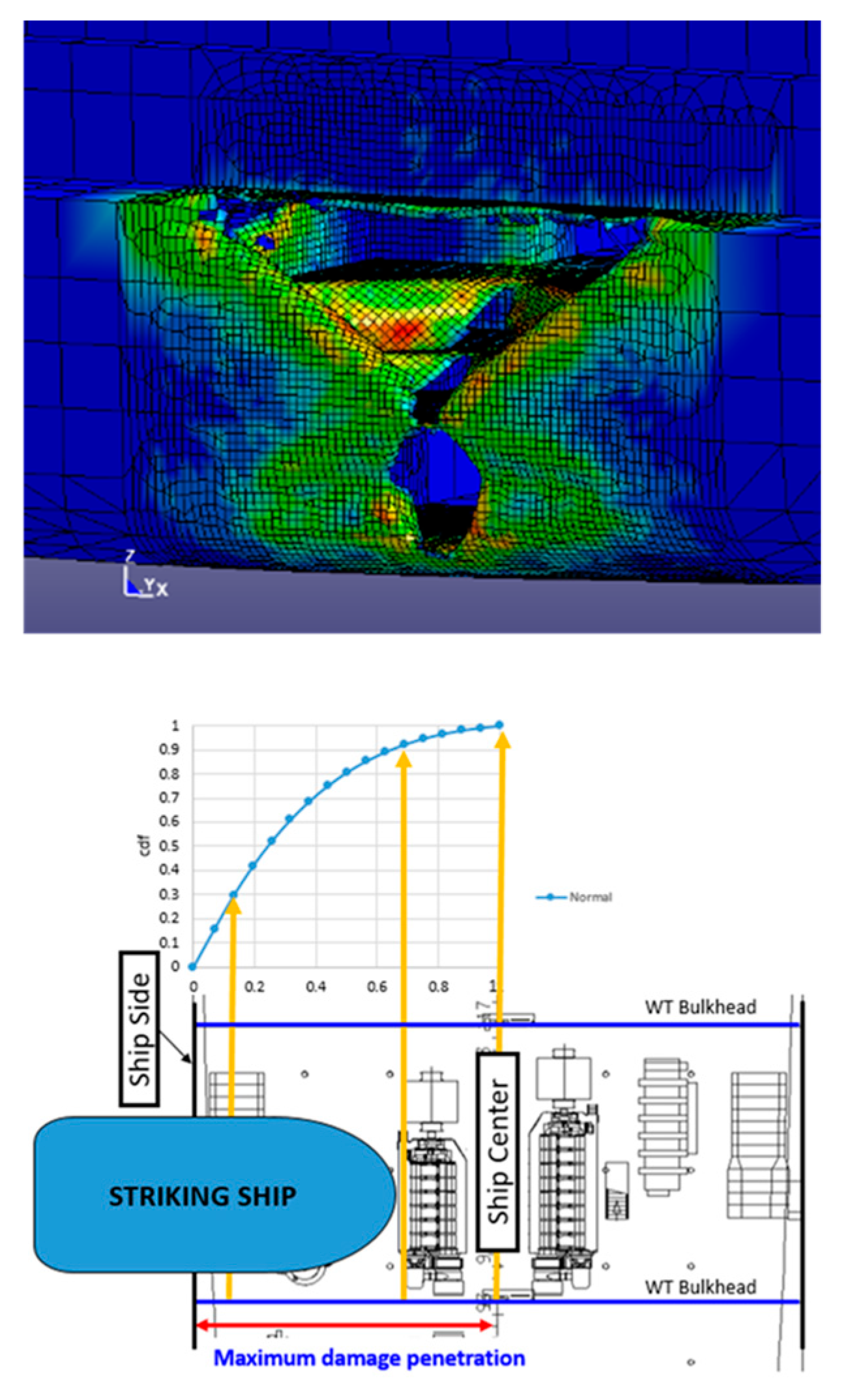
Figure 2.
(a) Depiction of SEM parameters with water elevation in the vehicle deck at the point of no return (PNR)—case of RoPax; (b) normal method employed by damage stability software considering the floodwater volume as a total water on the vehicle deck inside an undamaged tank (NB: “This proposal was considered at IMO alongside the traditional statistical approach and the latter prevailed but with the height of water on deck estimated on the basis of the expression (2), deriving from purposely-conducted model experiments at Danish Maritime Institute and Strathclyde University”).

Figure 3.
The IMO framework for passenger ship safety.

Figure 4.
EMSA II research outcome on RoPax level of R index.

Figure 5.
EMSA III research outcome on passenger ships’ level of R index.

Figure 6.
Casualty events for ships in the period 2011–2019.

Figure 7.
Capacities of largest passenger ships by year.

Figure 8.
Loss modalities of a damaged ship [58].
Figure 8.
Loss modalities of a damaged ship [58].

Figure 9.
Typical transient loss modality distribution for a SOLAS’90 cruise ship (model experiment and numerical simulation results).
Figure 9.
Typical transient loss modality distribution for a SOLAS’90 cruise ship (model experiment and numerical simulation results).

Figure 10.
Typical transient loss modality distribution for a SOLAS’90 cruise ship (numerical simulation results).
Figure 10.
Typical transient loss modality distribution for a SOLAS’90 cruise ship (numerical simulation results).

Figure 11.
Typical RoPax flooding scenario with water on deck.

Figure 12.
Floodwater on deck time-histories for varying Hs.

Figure 13.
Crashworthiness analysis and double hull (B/10) for passive flooding protection.

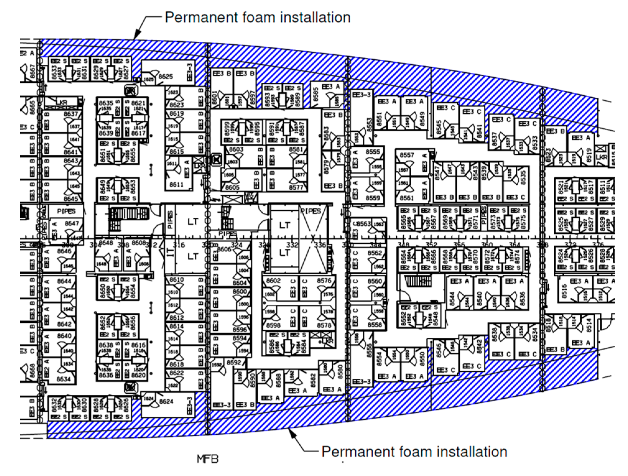
Figure 14.
Permanent filling of void spaces in the wing compartments of a cruise ship.

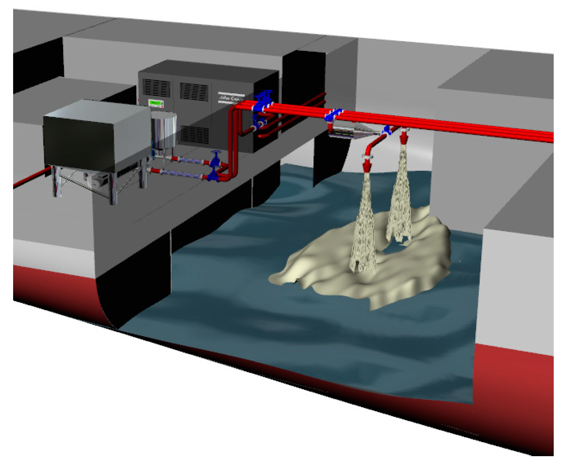
Figure 15.
Filling void spaces on top of floodwater in a critical damaged compartment.

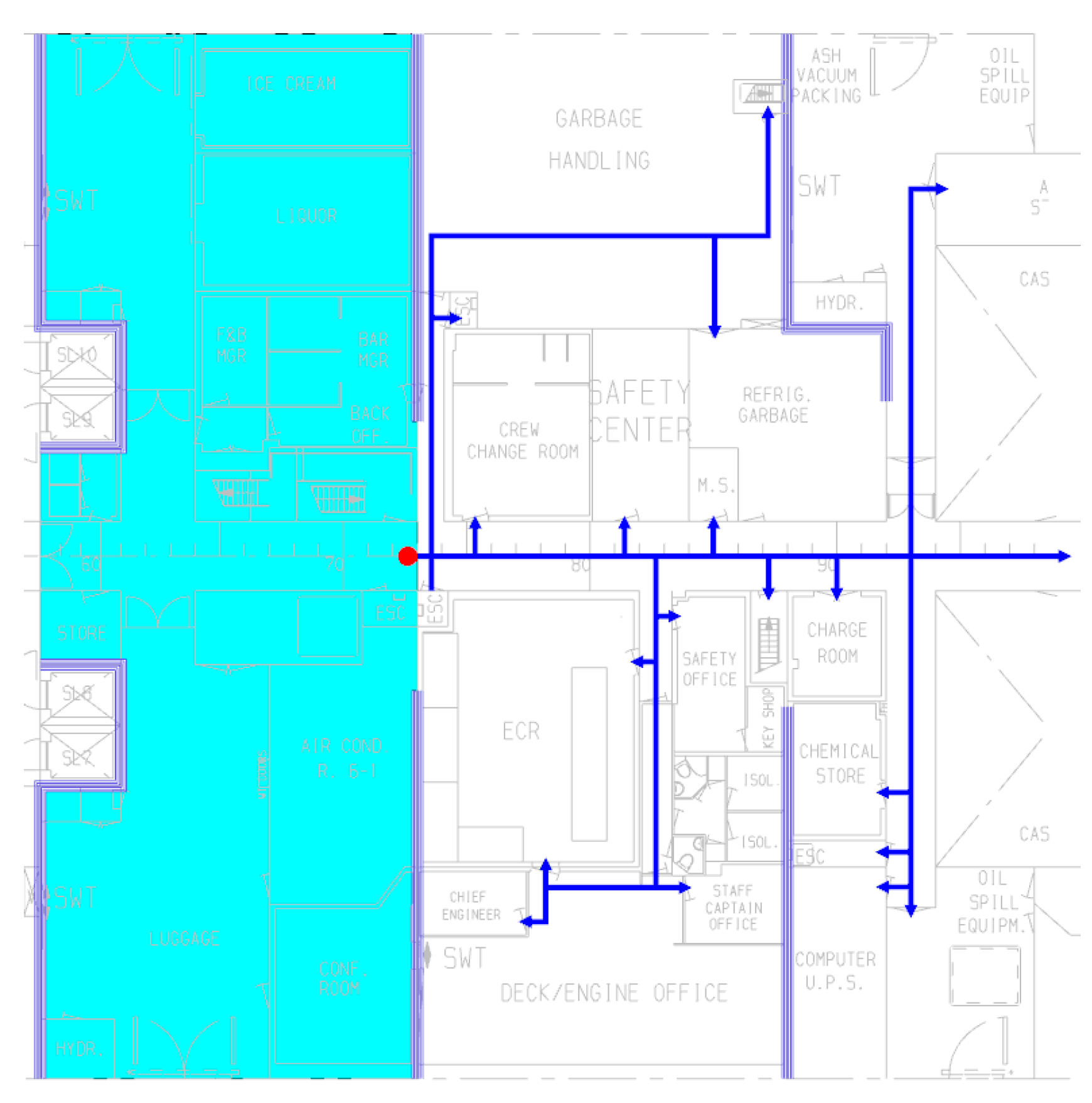
Figure 16.
A schematic of floodwater pathways in a complex cruise ship environment.

Figure 17.
Deployment of barriers to contain and control floodwater/fire progression.


Table 1.
A Record of Disasters and Related Legislation/Reconfiguration.
| Date | Disaster |
|---|---|
| 1854 | The first Merchant Shipping Act of 1854 is the first known legal requirement addressing safety at sea and concerning watertight bulkheads. It was enacted as a direct result of the rapid foundering of the Birkenhead in 1852 after striking a rock off South Africa, drowning some 500 women and children. The loss was rapid because the cavalry officers on board had holes cut in the transverse bulkheads in order to exercise their horses [46]. |
| 1862 | Pressure in parliament by the ship owners succeeded in repelling the Act because it was simply based on “mischievous” behavior. Within three years the London and the Amelia both sank in the same storm because of inadequate subdivision, with 233 people drowning in the London alone. It is frightening that from 1876–1892, 10,381 vessels belonging to the UK were totally lost, with 27,010 seamen and 3543 passengers drowning, with losses attributed to “Acts of God”. It is also worth noting that in 1878, HMS “Eurydice” was lost with nearly 400 lives lost as the ship was caught by a strong squall unprepared with some of her upper half-ports on the main deck open for ventilation and as she heeled under the force of the wind, water entered the open ports causing a sudden and complete loss of the ship. |
| 1883 | The Daphne capsized with the loss of 124 lives immediately after being launched in the Clyde. Sir Edward Reed, the commissioner of inquiry into the accident recommended that consideration should be given of the extent to which stability entered into design, construction, stowage, load line, and freeboard of ships. |
| 1891 | The Bulkhead Committee of the British Board of Trade recommended a 2-compartment standard for passenger ships, but the recommendations were not adopted. Unbelievably, in many parts of the world, one-compartment ships still exist, in spite of clear understanding today that the risk is completely “off the scale”. |
| 1895 | Germany introduced a 2-compartment standard, following the rapid loss of the Elbe with the death of 340 people. |
| 1913 | Following the Titanic catastrophe in April 1912 with a loss of 1430 lives, the first International Conference on the Safety of Life at Sea (SOLAS) took place in London to consider proposals by the UK, Germany, and France. The regulations formulated did not come into effect due to World War I. |
| 1914 | The Empress of Ireland capsized in the Gulf of St. Lawrence with 1024 lives lost. The need for subdivision, it was stated “gathers momentum”, but it was not until 1929 when a full International Conference was convened to consider this matter. However, the system of subdivision devised fell short of that agreed in 1913, evidence that IMO regulations reflect not experiential knowledge, as it is widely believed, but the compromise reached in each convention. |
| 1928 | The loss of the Vestris inspired proposals at the SOLAS Conference in 1930 for more secure engine room deck openings. |
| 1929 | The United States ratified the 1929 SOLAS Convention but only after the loss of the Mohawk by collision and of Morro Castle by fire. |
| 1948 | Loss of the Sankey with all hands and the Flying Enterprise in 1952 inspired legislation to prevent shifting cargoes. |
| 1948 | The SOLAS Convention and the first specific criterion on residual stability standards with the requirement for a minimum residual GM of 0.05 m. This represented an attempt to introduce a margin to compensate for the upsetting environmental forces. |
| 1953 | Princess Victoria capsized and sank when large waves burst open the stern door in rough weather with the car deck and starboard engine room flooding (134 died). |
| 1955 | A fire in the engine room of the Empire Windrush, with large loss of life, inspired the dispersal of fire pump controls. |
| 1956 | The Andrea Doria, built under SOLAS 1948 requirements, which were a slight improvement of the 1929 Conference, capsized in heavy seas and this alerted the profession to the fact that the effect of waves on safety ought to be considered. This accident strongly influenced proposals made to SOLAS 1960. |
| 1974 | Straitsman capsized and sank whilst approaching its berth with its vehicle door partly open as a result of squat, flooding the vehicle deck. |
| 1974 | IMO published Resolution A.265 (VIII)—regulations dealing with subdivision and damage stability on a probabilistic basis—as equivalent to SOLAS deterministic rules. |
| 1987 | Herald of Free Enterprise capsized when the bow wave and bow-trim combined to bring the open bow door underwater, flooding the vehicle deck. |
| 1987 | Santa Margarita Dos capsized in port in Venezuela due to heeling while loading vehicles as a result of flooding of the vehicle deck. |
| 1987/1988 | Following the Herald of Free Enterprise accident in 1987 with the loss of 193 lives and a public outcry, SOLAS’90 came into effect for new ships build after 1990, introducing a considerable increase in damage stability standards [47]. Proposals by the UK to phase-in upgrading of existing ships to SOLAS’90 was rejected by IMO but a regional agreement was reached by the North West European Nations. |
| 1991 | After a madman set fire on the Scandinavian Star causing the death of 169 people, retrospective legislation was introduced for the first time in respect of enhanced “Structural Fire Protection”. |
| 1994 | The Estonia was lost involving the loss of 852 lives. IMO rejected proposals for capability of withstanding water on deck of Ro-Ro passenger ships. A regional agreement was reached (“Stockholm Agreement”) by the North West European Nations and later by the whole EU, Australia, and Canada [48]. |
| 1995 | In the 1995 SOLAS Diplomatic Conference SOLAS’90 was adopted as a global safety standard of damage stability. A proposal to IMO of a new damage stability framework based on probabilistic methods by the North West European Nations, following intensive research in the wake of Estonia, was tabled as an item for long term discussion. The proposal considered explicitly the effect of waves and water on deck (performance-based criteria) deriving from the work undertaken by the Strathclyde Stability Research Group and allowed for various safety nets, aiming to ensure that the Estonia disaster would never happen again. A probabilistic framework was also developed and proposed [49], which formed the foundation for the EU Project HARDER [30], where the foundation of the probabilistic regulations for damage stability was developed and brought to IMO, leading eventually to SOLAS 2009. |
| 2000 | Express Samina: Flooding of the engine room and spreading of floodwater through open watertight doors, leading to 81 fatalities. |
| 2006 | Al Salam Boccaccio’98: Following fire on the car deck, sprinklers were activated, which led to floodwater being accumulated on the vehicle deck because of blocked freeing ports, leading to the vessel capsizing with 1002 dead. |
| 2012 | Costa Concordia: Side grounding damage, leading to up-flooding and capsize with 32 casualties. |
| 2014 | MV Sewol: Overloading and inadequate stability, leading to vessel listing heavily following a turn and eventually capsizing with 295 casualties, mostly children. |
Table 2.
RoPax disasters due water on the vehicle deck.
|
Table 3.
Technical information on retrofitted Ro-Ro passenger ships for Stockholm Agreement compliance [52].
Table 3.
Technical information on retrofitted Ro-Ro passenger ships for Stockholm Agreement compliance [52].
| Item | Technical Information |
|---|---|
| Transverse Doors on the Car Deck | Major modification as it effects the overall cost, survivability, and operation significantly |
| Ducktail | Major modification as it effects the overall cost, survivability, and operation significantly |
| Ducktail Sponsons | Major modification as it effects the overall cost, survivability, and operation significantly |
| Side Sponsons | Major modification as it effects the overall cost, survivability, and operation significantly |
| Side Casings | It could be major or minor conversion, depending on cost and effect on cargo capacity |
| Making Existing Rooms Watertight on the Car Deck | Minor |
| Internal Tank—Re-arrangement | Minor |
| Buoyancy Tanks | Minor |
| Additional Subdivisions | Minor or major, depending on the location and size of the conversion |
| Making Existing Rooms Watertight below the Car Deck | Minor |
| B/5 Longitudinal Bulkheads | Minor or major, depending on the location and size of the conversion |
| Cross-flooding Arrangement | Minor |
| Heeling Tanks | Minor |
| FW tanks | Minor |
| Ballast Tanks | Minor |
| Stabilizing Tanks | Minor |
| Scupper Arrangements | Minor |
| Additional Center Casing on Car Deck | Minor |
| Stern Boxes | Minor |
| In Flooding Valves | Minor |
| New Bulbous Bow | Major |
| Foam Fillings in Void Tanks | Major |
© 2020 by the authors. Licensee MDPI, Basel, Switzerland. This article is an open access article distributed under the terms and conditions of the Creative Commons Attribution (CC BY) license (http://creativecommons.org/licenses/by/4.0/).
Share and Cite
MDPI and ACS Style
Vassalos, D.; Paterson, D. Reconfiguring Passenger Ship Internal Environment for Damage Stability Enhancement. J. Mar. Sci. Eng. 2020, 8, 693. https://0-doi-org.brum.beds.ac.uk/10.3390/jmse8090693
AMA Style
Vassalos D, Paterson D. Reconfiguring Passenger Ship Internal Environment for Damage Stability Enhancement. Journal of Marine Science and Engineering. 2020; 8(9):693. https://0-doi-org.brum.beds.ac.uk/10.3390/jmse8090693
Chicago/Turabian StyleVassalos, Dracos, and Donald Paterson. 2020. "Reconfiguring Passenger Ship Internal Environment for Damage Stability Enhancement" Journal of Marine Science and Engineering 8, no. 9: 693. https://0-doi-org.brum.beds.ac.uk/10.3390/jmse8090693
Note that from the first issue of 2016, this journal uses article numbers instead of page numbers. See further details here.