Article

Effects of Gap Resonance on the Hydrodynamics and Dynamics of a Multi-Module Floating System with Narrow Gaps

1
Key Laboratory of High Performance Ship Technology (Wuhan University of Technology), Ministry of Education, Wuhan 430063, China
2
School of Naval Architecture, Ocean and Energy Power Engineering, Wuhan University of Technology, Wuhan 430063, China
3
China Harbour Engineering Co., Ltd., Beijing 100027, China
*
Author to whom correspondence should be addressed.
J. Mar. Sci. Eng. 2021, 9(11), 1256; https://0-doi-org.brum.beds.ac.uk/10.3390/jmse9111256
Submission received: 15 August 2021 / Revised: 9 November 2021 / Accepted: 10 November 2021 / Published: 12 November 2021
(This article belongs to the Special Issue Ocean and Shore Technology (OST))

Abstract

:
Multi-module floating system has attracted much attention in recent years as ocean space utilization becomes more demanding. This type of structural system has potential applications in the design and construction of floating piers, floating airports and Mobile Offshore Bases (MOBs) generally consists of multiple modules with narrow gaps in which hydrodynamic interactions play a non-neglected role. This study considers a numerical model consisting of several rectangular modules to study the hydrodynamics and dynamics of the multi-module floating system subjected to the waves. Based on ANSYS-AQWA, both frequency-domain and time-domain simulations are performed to analyze the complex multi-body hydrodynamic interactions by introducing artificial damping on the gap surfaces. Parametric studies are carried out to investigate the effects of the gap width, shielding effects of the multi-body system, artificial damping ratio on the gap surface, and the dependency of the hydrodynamic interaction effect on wave headings is clarified. Based on the results, it is found that the numerical analysis based on the potential flow theory with artificial damping introduced can produce accurate results for the normal wave period range. In addition, the effects of artificial damping on the dynamics and connector loads are investigated by using a simplified RMFC model. For the case of adding an artificial damping ratio of 0.2, the relative heave and pitch motions are found to be reduced by 33% and 50%, respectively. In addition, the maximum cable and fender forces are found to be reduced by 50%, compared with the case without viscosity correction.

1. Introduction

With the size and weight of offshore floating structures being continually increased to meet the needs for exploiting various resources from the ocean, the multi-module floating system has become increasingly popular due to its advantages such as the ease of fabrication, transportation, and installation as well as the reduction of the overall wave-induced longitudinal loads. Many applications of such systems can be found in offshore and ocean engineering, for instance, the floating pier [1,2], floating airport [3,4], and Mobile Offshore Base (MOB). In addition, many operations may involve multiple floaters operating in close proximity with temporal connections, such as the side-by-side operation of an FLNG and an LNG carrier [5] and the catamaran float-over deck installation for a floating Spar platform [6,7]. Different from a single floater, the multi-module floating system may involve complex hydrodynamic interactions and dynamic interactions between different modules via the connectors [8,9,10]. This complex problem has attracted enormous interest in the field of naval architecture and ocean engineering. Much literature has been dedicated to investigating the hydrodynamic and dynamic interaction problem between multiple bodies in waves for decades, for example, the experimental studies [11,12] and theoretical analyses [13,14]. Meanwhile, numerical investigation has gradually become an important method for investigating multi-body hydrodynamics, with the continuous improvement of computers’ computation capability and the advancement of numerical models. Wang et al. [15] adopted the linear potential flow theory to study the hydrodynamic interaction between two semi-submersible types of VLFS modules in the frequency domain. Li et al. [16] built a numerical wave tank based on the fully nonlinear potential flow theory to investigate the fluid resonant phenomenon at the gap in-between the adjacent floating bodies. Their results showed that the dominant resonant mode may transfer from the piston type to the sloshing type as the gap distance increases from narrow to wide. In some cases, it is necessary to account for the second-order effects such as the mean drift forces and more complex time-varying nonlinearities [17]. In this regard, Sun et al. [18] applied a second-order diffraction code DIFFRACT to investigate the water wave diffraction by two parallel closely spaced rectangular barges, and the relationship among the wave frequencies, wave force amplitudes, and gap width was presented.
Based on the linear potential flow theory, frequency domain hydrodynamic analysis of the multi-body system can be readily conducted by the standard panel codes such as AQWA [19]. However, the frequency domain model can only analyze linear problems. Thus, the time-domain model established by Cummins [20], known as the Cummins equation, has been widely used to analyze the nonlinear dynamics of multiple bodies [21,22,23]. This method is a hybrid frequency-time domain model since the parameters of the Cummins equation can be obtained based on the frequency-domain results. In the Cummins equation, the kernel of the convolution term is known as the Impulse Response Function (IRF), which can be calculated based on the integration of the added damping coefficients. Lewandowski [24] studied the wave-induced motion of two vessels in close proximity and investigated the effects of the pumping and sloshing modes of the gap fluid resonances on the IRFs. It was observed that the IRFs of the multi-body floating system show much more lightly damped features than those of the single floater. This feature would cause difficulty in establishing a constant parameter time-domain model for the multi-body floating system by replacing the time-consuming convolution term with state-space models, as discussed by Chen et al. [6], though the constant parameter method works well for the single floater cases such as the modeling of float-over deck installations [25,26]. In addition to the hybrid frequency-time domain method, some fully time-domain codes have been developed. Feng et al. [27] developed a fully nonlinear time-domain model to simulate the wave resonances in a narrow gap between two barges. Yang et al. [28] developed a full-time-domain method for coupled dynamic analysis of the wave interaction among offshore structures. Instead of transforming frequency domain results into the time domain, the wave forces are computed in the time domain for every time step by their methods. However, these fully time-domain codes are much more computationally demanding compared with the hybrid frequency-time domain model. Therefore, the latter one has been more widely used in engineering analyses. Koo et al. [29] investigated the hydrodynamic interaction and mechanical coupling effects of two floating platforms by using a time-domain coupled dynamics analysis method. Their results show that the cross-coupling terms in the off-diagonal region of the full hydrodynamic coefficient matrix play an important role in the case of multi-floaters in close proximity.
The aforementioned numerical studies are all based on the potential flow theory, which has been widely used to analyze the wave-structure interaction problems in offshore engineering. However, this method ignores the fluid viscosity and thus cannot accurately predict the gap resonant behaviour arising from the interactions between the waves and the multi-body system. Specifically, it has high precision in predicting the resonant wave frequencies, while it may overestimate the resonant wave elevation at the gap between the floaters [15]. In addition, this overestimation may cause large errors in the prediction of the hydrodynamic coefficients at the resonant frequencies and may even making the IRFs being more unrealistically lightly damped. In addition, the overestimated hydrodynamic interaction may make the time-domain model difficult to converge [6]. Therefore, further corrections are needed to improve the accuracy of the frequency-domain simulations, such as using the rigid lid method and damping lid method. Huijsmans et al. [30] used the rigid lid method to circumvent the unrealistic high velocities of the water particles hitting on the ship’s hull. The damping lid method was used originally to account for the energy dissipation in sloshing problems [31]. Chen [32] firstly introduced the artificial damping term to suppress resonant fluid in the gap between adjacent ships. Subsequently, this method has been recognized by many scholars. Yao and Dong [33] also studied the wave elevation in the gap by applying a dissipating parameter and performed a sensitive study of the dissipating parameter. Research conducted by Zhao et al. [34] proved that potential flow can accurately and highly efficiently simulate fluid sloshing in the time domain by using the artificial damping model. In addition, Zhao et al. [35] developed a numerical code considering the artificial damping factor based on the potential flow theory to predict the interactions between connected vessels’ motions and liquid sloshing. In addition to the numerical research verification, using an appropriate artificial damping lid can make the linear potential theory model more accurate in the analysis of the spacing resonance, which has been substantiated by the experimental test [36].
Although multi-body hydrodynamics and the gap resonance have been widely investigated, they were mostly considered for two parallel ships in deep water conditions. Meanwhile, the spacing dimensions between the adjacent floaters are not so small compared to the hull width. However, in many marine installations, such as the floating airport and floating artificial islands, several floating bodies often work together at a small distance from each other. In addition, the resonant frequency of the gap fluid between three or more bodies is significantly different from that of the two-body case, and the number of bodies would also have an important influence on the motion characteristics of the gap fluid. At the same time, different from the deep-water condition, the aforementioned marine installations are usually located in shallow water areas, and the change of water depth has a significant influence on their hydrodynamic interaction characteristics and the gap fluid resonance phenomenon. On top of this, the present research aims to study the gap resonance in finite water depth when the ratio of spacing to hull size is less than 1%, which can be commonly found in multi-module VLFS systems. Considering that the hydrodynamic interactions between multiple floaters stick out in head sea for shielding effects. The hydrodynamic responses between adjacent rectangular boxes joined fore and aft at extreme proximity in the head sea are discussed in this study. The resonant frequency prediction in the frequency domain and the effect of artificial damping on the impulse response function and connector load in the time domain are both investigated.

2. Theoretical Background

A multi-module system is a common application associated with many offshore activities and installations, which involves complex hydrodynamic interaction. Hydrodynamic interaction including both coupling and shielding effects concerns the effects of one floating body’s flow field on the others. Hence, it is a complicated but necessary task to conduct multi-body hydrodynamic interaction analysis. In this study, approaches based on three-dimensional potential theory are employed to solve this task by using the well-proven hydrodynamics software AQWA. The sketch of the multi-module system is illustrated in Figure 1. Different from the single floater case, the total degrees of freedom of the multi-body system is 6 × M, where M is the number of floaters. The total velocity potential can be generally expressed as follows:
φ ( X ) e i ω t = [ m = 1 M ( φ I + φ D ) + m = 1 M j = 1 6 φ r j m x j m ] e i ω t
where φ I is the individual incident velocity potential, φ D is the diffraction wave potential, and x j m is the amplitude of motion of the j-th degree of freedom of the m-th structure. φ r j m is the radiation potential due to the unit j-th motion of the m-th structure while other structures remain stationary, which is determined by the boundary conditions of the wet surface.
Due to the lack of viscosity and energy dissipation terms in the potential flow theory, unrealistic wave resonant phenomena will appear in the gap fluid between adjacent modules. When the gap size is large, the phenomenon that the water surface has multiple crests on the wave surface is called the “sloshing mode”, which is different from the “zeroth mode” [37] or “pumping mode” [24] that the wave surface is flat and moves vertically as a whole at a frequency lower than the first-order resonance mode. In order to predict the resonance frequency of the adjacent floating system, Lewandowski et al. [24] suggest the n-th mode of sloshing frequency can be calculated as:
ω n = n g π d
where g is the gravity acceleration and d stands for the gap width.
However, the above equation is only good for “deep water”, which was verified by Chen et al. [7]. While for shallow water, the resonance frequency determined by the traditional deep water formula cannot work well, the accuracy of Equation (2) will be greatly reduced. Meanwhile, Equation (2) cannot be used to predict the pumping mode. For predicting pumping frequency, Newman [38] estimated the pumping mode frequency by treating the water in the gap as solid body, and the critical frequency occurs at:
ω 0 g D
where D is the draft.
Since the pumping frequency is also related to the parameters such as the gap width d, the prediction accuracy of Equation (3) is insufficient. In order to illustrate the effect of resonance on water surface elevations of the gap in shallow water, parameters such as the gap width, draft, and water depth were taken into consideration by Moradi et al. [39] to predict the pumping mode frequency:
ω = g d L h D + D
where, d represents the gap width, L denotes the floating body length and h represents the water depth. Yet it is not the case with large spacing, considering that the scale ratio of the extremely narrow gap in the length direction of the float is negligible, while the breadth of the float plays an important role in the estimation of the resonant frequencies of the multi floating system. Given that the scale effect of the tiny slit, the resonant frequency of the fluid in the gap is derived from Equation (4) as:
ω = g d B h D + D
where B is the floating body breadth.
In view of the unrealistic wave phenomena at the critical frequencies, the wave force and hydrodynamic coefficients are affected to some extent. It is necessary to suppress these unreal wave phenomena in the analysis of hydrodynamic interaction problem, a damped free-surface boundary is applied on the free-surface between adjacent structures by wave-absorbing beach method to simulate the additional damping due to viscous effects [40], this condition is expressed as:
ω 2 g ( α 2 f 1 1 ) φ 2 i ω 2 g α f 1 φ + φ z = 0   where   Z = 0
f 1 = { sin 2 ( π 2 ω ω 0 )   where   ω < ω 0   ( ω ω 0 ) 2   where   ω ω 0
ω 0 = max { 0.1 , π g d }
where α denotes the damping factor, f 1 is a function that relates to the gap width d.
By adding the artificial damping, the frequency-domain hydrodynamic analysis of the multi-floating body system can be readily carried out in AQWA, from which the hydrodynamic coefficients, wave excitation forces and the gap fluid elevation can be obtained. For the multi-body system, the equation of motion in the frequency-domain can be expressed as the following matrix form:
X ^ ( i ω ) = F ^ E ( i ω ) / { ω 2 [ M + A ( ω ) ] i ω B ( ω ) + C }
where, X ^ ( i ω ) represents the 6m × 1 vector of Response Amplitude Operator (RAO) of the multiple bodies; M, A(ω) and B(ω) are the (6M) × (6M) structural mass, added mass, and damping matrices, respectively; C is the hydrostatic stiffness matrix assembled by each 6 × 6 sub-hydrostatic stiffness of individual structure along the diagonal; F ^ E ( i ω ) is the 6M × 1 vector of the wave excitation force.
However, the frequency domain model can only analyze linear problems. The time-domain model is needed to analyze the dynamics of the multi-module floating system with nonlinear effects being considered such as the mooring system. Cummins equation [19] provides an attractive means of analyzing the time-domain motions of floating structures. For the case of the freely floating condition, the Cummins equation has the following form:
[ M + A ( ) ] X ¨ ( t ) + 0 t K ( t τ ) X ˙ ( τ ) d τ + C X ( t ) = F E ( t )
where, K(t) is the matrix of the impulse response functions, F E ( t ) denotes the time-domain wave excitation force.
The above model can be evaluated using a numerical integration algorithm such as the 4th order Runge-Kutta algorithm. In AQWA, Equation (10) is evaluated using the semi-implicit two-stage predictor-corrector scheme [40]. Ogilvie [41] established the relationship between the frequency and time domain models, which can be expressed as:
A ( ω ) = A ( ) 1 ω 0 K ( τ ) sin ( ω τ ) d τ
B ( ω ) = 0 K ( τ ) cos ( ω τ ) d τ
The impulse response function can be calculated by using the Inverse Fourier Transformation (IFT):
K i j ( t ) = 2 π 0 ω [ A i j ( ω ) A i j ( ) ] sin ( ω t ) d ω
K i j ( t ) = 2 π 0 B i j ( ω ) cos ( ω t ) d ω
where, i, j = 1, …, 6M.
Considering that Equation (14) converges more efficiently, it is usually selected for calculating the IRFs [6,42]. Whereas the hydrodynamic results calculated by the program can only be up to a certain frequency in practice. In order to get the hydrodynamic coefficients beyond the certain frequency σ, a polynomial fitting method is used [43]. Therefore, the calculation of the K(t) and the damping coefficient at higher frequency can be derived in the following ways:
K ( t ) = 2 π 0 σ B i j ( ω ) cos ( ω t ) d ω + 2 π σ B ^ i j ( ω ) cos ( ω t ) d ω
where B ^ i j ( ω ) denotes the asymptotic approximation of B i j ( ω ) at high frequencies, which tends to zero as the frequency increases to infinity.
In the freely floating condition, the time-domain and frequency-domain models can be transformed into each other and are equivalent. The time-domain wave excitation forces in Equation (10) can be obtained from the frequency-domain calculations:
F E ( t ) = Re [ F ^ E ( i ω ) e i ω t ]
Thus, the accuracy of the time-domain model can be confirmed by comparing the time-domain response results with the RAO-based response in the case of the freely floating condition. The RAO based responses can be derived in the following expression:
X R A O ( t ) = Re [ X ( i ω ) e i ω t ]
However, due to the strong hydrodynamic interaction effects, the added damping coefficients would drastically change at the resonant frequencies, resulting in significant errors in the calculation of the impulse response function by Equation (15). In addition, the impulse response function may exhibit weakly damped behaviour, resulting in that the time domain results are difficult to converge. Therefore, this study explores the convergence of the time-domain model by considering viscosity correction in the frequency-domain using the artificial damping lid method.
Considering that most large floating structures assembled from multiple modules require high structural integrity, connectors are needed to connect different modules to each other. In this study, flexible connectors are considered and the Rigid-Module-Flexible-Connector (RMFC) model is established in AQWA. As shown in Figure 2, linear cable and fender elements are selected to achieve a simplified simulation of the flexible connector system in AQWA.
The linear elastic cable is defined by the stiffness and the initial un-stretched length, which is assumed to have no mass and is therefore represented geometrically by a straight line. The fender acts only in compression between two structures. The cable and fender forces can be calculated as [40]:
T c a b l e = { K c ( L c L c 0 )   if   L c > L c 0 0   if   L c L c 0
T f e n d e r = { K f ( L f 0 L f )   if   L f L f 0 0   if   L f > L f 0
where, Kc and Kf represent the stiffnesses of the cable and fender, respectively; Lc and Lc0 denote the instantaneous and un-stretched length of the linear cable; Lf and Lf0 are the instantaneous and initial compression of the fender element.
By considering both the effects of the connector system and mooring system, the dynamics of the multi-module floating system can be evaluated by the following time-domain model:
[ M + A ( ) ] X ¨ ( t ) + 0 t K ( t τ ) X ˙ ( τ ) d τ + C X ( t ) = F E ( t ) + F C ( t ) + F M ( t )
where, FC(t) and FM(t) represent the vectors of the connector force and mooring force, respectively.
Based on the above theory, frequency-domain hydrodynamic analysis and time-domain simulations are both carried out in AQWA and the results are discussed in the following sections.

3. Results and Discussions

3.1. Particulars of the Analysed Multi-Module System

In this study, the analyzed multi-module system is loosely based on the model designed by the CCCC Research & Development Project, which consists of several identical rectangular boxes. The parameters of the single module are summarized in Table 1. the centre of gravity of the single module is located at its geometric centre and the mass is assumed to be uniformly distributed. The module is symmetric along both x and y axes, and incident head waves are considered. The water depth is 50 m.

3.2. Frequency-Domain Simulations

In this study, the frequency-domain hydrodynamic analyses of the multi-module system are carried out by using ANSYS-AQWA. The plan view of three configurations is shown in Figure 3.
Given that the head sea (wave angle = 180°) is the main wave condition considered, the three modes of motion including surge, heave, and pitch are the main focus of this study. In Figure 4, the response amplitude of each windward module of the three models is shown. All three curves of different module numbers showed a similar trend, with only a slight disturbance occurring around 1.8. In the multi-module model, the RAOs of the windward module of the multi-module system were separated from the single-module result in surge response, but the deviation value was small and its influence could be ignored. However, as expected, the heave and pitch motions seem to be affected by the number of structures. Among them, the pitch response curves appear to change with the increase of module number, the peak number increase from one to three in the range of 0.5–1 rad/s. The hydrodynamic results are somewhat different, strong fluid resonance caused by the hydrodynamic interaction can be found by increasing the number of structures. Figure 5 compares the diagonal terms of the damping and added mass coefficient matrices of the windward modules in the three models. Compared with the case of 1 module, the damping terms of 2 and 3 module models appear obvious resonance peaks. The wave frequency is about 1.7 rad/s where 2 and 3 module system added damping coefficient extremum diagonal entries appear. And the added mass experiences first a maximum and then a minimum (sometimes becoming negative) roughly centered on the frequency at which the damping term appears the maximum value. The same resonant frequency of 2-module and 3-module operating conditions also illustrates that the number of floating bodies does not affect the resonance phenomenon. While the peak value of the 2-module model is a little bit larger than that one of the 3-module model, which means that the effect of resonance on the hydrodynamic coefficients is gradually weakened with the increase of the number of modules when the gap width is 1 m.
The model of 3 modules is used for the investigation of gap width effects for variable gap widths. Different from the spacing scale of floating structures in offshore operations such as the catamaran float-over deck installation and offshore lifting operations, the floating airports and artificial islands have higher requirements on structural continuity and thus have much smaller module spacing. Figure 6 shows the pitch RAOs of modules in different locations with respect to wave frequency in heading 180°. It can be observed that different from the larger gap width, the extremely close spacing within 1 m does not reflect significantly different motion response characteristics. However, with the further narrowing of the spacing, the small fluctuation phenomenon in the high-frequency area also disappeared gradually, and the accordance of the curve was improved. That means the hydrodynamic resonance effect on the motion response is diminishing, further reduction of module spacing has no essential effect on the motion characteristics of the floating body. It should be noted that modules in different locations exhibit different characteristics, the farther the module is from the wave, the curve is getting closer and closer to the monomer case, and the influence of the multi-body effect on the motion characteristics of floating bodies is gradually weakened. This is caused by the shield effects of multiple hydrodynamic interferences, and the shielding effect of the module will be more and more obvious with its position in the back of the wave in a series arrangement.
Rather than, for the hydrodynamic results, the effects of the gap width are stark. The resonant frequency of the 3-module model increases with the decrease of the spacing, as shown in Figure 7. Unlike the sloshing model with large spacing, where there are multiple resonances, there is only one resonance within one meter of each other. This is due to the gap width being much less than half the wave wavelength of the corresponding calculated frequency. While the added damping in surge has been a dramatic change of concern, there are two passive peaks in the curve of 0.25 m spacing. This phenomenon shows that due to the existence of the mini slit, the hydrodynamic interaction between the floating bodies becomes complicated, the water in the slit would be reflected and superimposed several times between the side slabs on both sides and the resonance of three modules of the same scale occurs at two relatively close frequencies.
Although there will be a large error in the calculation of the resonance peak of the hydrodynamic coefficients in the potential theory, it has high reliability in the calculation of the resonance frequency. Table 2 summarized the resonance frequency calculated by Equation (5). As shown in the table, the resonant frequency of multi-floating systems with gap spacing of 1 m, 0.5 m, and 0.25 m are 1.79 rad/s, 1.97 rad/s, and 2.08 rad/s respectively. These results are all in fairly good agreement with the numerical calculation, the margin of error was 4.5%, 5.6%, and 3.4%, respectively. Which cross-verified the high prediction accuracy of the modified equation in predicting the resonance frequency. The resonance phenomenon only occurs within a certain frequency range, and the resonance behaviour is also constrained in a relatively narrow frequency band.
As shown in Figure 8, one phenomenon that is worth pointing out is that the hydrodynamic coefficient resonance peak of the middle module is larger than that of the two end modules, where the values of the two end modules are similar. The peak resonant frequency of the intermediate module is about twice as high as that of the two ends, which means the hydrodynamic effect of the box in the middle position was found to be the largest and decreases gradually to both sides. This indicates that the shielding effect plays a non-ignorable role in the hydrodynamic calculation of the multiple module systems, and the shielding effect mainly affects the values of the hydrodynamic coefficient of the floating bodies. At the same time, the hydrodynamic coefficient curves of modules at different positions show the same variation. This indicates that although the peak value results are different, the modules at each position can fully reflect the hydrodynamic resonance phenomenon by itself, which is representative of the analysis of hydrodynamic interactions in the multi-module system.
From the above part, it is easy to illustrate that the hydrodynamic resonance phenomenon at the specific frequency calculated by potential theory is extremely significant under the condition of a small gap i.e., with spacing less than 1 m. In order to improve the calculation accuracy at the resonant frequency in an ideal fluid, a new damped free-surface boundary introduced by Equation (6) is applied on the free surface between adjacent structures. Through the introduction of the artificial damping coefficient, the extreme peak of hydrodynamic coefficients is corrected effectively. In this study, four different artificial damping ratios are considered to analyze the influence of the value on the system with such a narrow gap. Figure 9 compares the hydrodynamic coefficients of the windward module of a 3-module system spaced 1 m apart with the range of artificial damping ratio α 0–0.2 (according to Cheetham, et al.) [44]. The value of 0 will give no effect, The value of 0 will give no effect, whose corresponding calculation results are representative of the traditional potential flow theory without viscosity correction, while 0.2 may result in heavy damping of surface elevation. It can be seen that the curves of the hydrodynamic coefficients have become more and more moderate as the artificial damping ratio increases near the resonance frequency, the peak value of the added damping terms decreases gradually and the maximum and minimum of the added mass are reduced at the same time. By comparing three modules in different locations, the same artificial damping ratios are found to play the same role.
The response of the free surface in the gap between modules is of interest. The amplitudes of the waves induced by modules under different artificial damping ratios are shown for the 1 m spacing in Figure 10 and Figure 11. Due to the small gap scale, less than an integral multiple of half wavelength, the type of resonant behaviour in the narrow gap where the water surface moves vertically and simultaneously remain horizontal has been referred to as the ‘‘pumping mode’’. This is different from the higher resonances occurring in a wider gap, known as ‘‘sloshing modes’’. In view of the strong shielding effect between the modules arranged in series, the phenomenon of wave surface elevation in the back gap is much milder than that in the front gap. The maximum peak frequency in the wave surface variation diagram is further cross-verified with the hydrodynamic results above, and it is found that with the introduction of water viscosity term in the gap the unrealistic surface elevation near the resonant frequency is significantly decreased. Same as the variation of hydrodynamic coefficient, the correction effect becomes more obvious when the artificial damping ratio α gets larger, in which the wave surface in the back gap is more sensitive to the larger damping ratio.

3.3. Time-Domain Simulations

This section investigates the accuracy of the time-domain model built upon the artificial damping ratio introduced in ANSYS-AQWA. In the time domain analysis, the Cummins equation, as shown in Equation (10) is generally accepted as the best method, while the convolutions must be numerically computed at each time step. When hydrodynamic interactions are present, the multiple reflections between adjacent floating bodies would lead to the accumulation of radiation energy assuming no energy dissipation [45]. Hence, it is impractical to carry out the convolutions back to the time at which the amplitude of the Impulse Response Functions (IRFs) is zero. Which would also cause errors in the calculation of IRFs when sharp resonances in the damping coefficients appear at the resonant frequencies. For reasons that the shielding effects can be ruled out, the impulse response functions for the windward module in the surge, heave, and pitch modes for three different module number cases are presented in Figure 12. The impulse response functions shown here are calculated by Equation (4) based on the integration of the added damping coefficients with MATLAB mathematical software. The impulse response function of a single barge decays to zero quickly, whereas it is found that obvious oscillations persist in the two and three module configurations till the cut-off time (i.e., 40 s). This is caused by the constant reflection of the radiation between ships, and multiple reflections will result in permanent radiation energy when assuming no energy dissipation. This problem can be solved by using the artificial damping lid method, which can simulate the additional damping due to viscous and separation effects to suppress these unrealistic wave phenomena by the ordinary potential theory. Figure 13 plots the comparison of the calculated impulse response function K1,1(t), K3,3(t), and K5,5(t) for the configuration of the three-module system spaced 1 m apart with the range of artificial damping ratios 0–0.2. For the 0 ratio case, the calculated impulse response functions exhibit lightly damped behaviour such that significant oscillations persist due to the hydrodynamic interaction, which is consistent with the previous results of Lewandowski [24] and Chen et al. [6]. By multiplying the damping ratio, the impulse response functions smoothly decay to zero gradually, which illustrates the precision of time-domain calculation can be improved by the introduction of the damping coefficient and can help to make the time domain results more accurate.
For a multi-module system, because of the coupling relationship between each body, the cross-coupling terms in the off-diagonal region of the calculated impulse response functions are analyzed. In which, the coupling items between two adjacent modules show consistent characteristics. Figure 14 and Figure 15 compare the cross-coupling terms of the pre- and intermediate modules and the pre- and post-modules respectively. The numbers 1–6, 7–12, 13–18 respectively represent the 6-DOF movement of the three modules from the heading wave to the tail. It should be noted that some terms of the IRFs starting from a negative value are caused by the negative peak damping resonance of the corresponding coupling term. Considering the relationship between different modules in the same direction of motion, the fluctuation range of coupling impulse response functions of non-adjacent is weaker than that of adjacent modules. Meanwhile, it can be observed that the coupling terms of modules at both ends are more sensitive to the introduction of artificial damping lid than those of adjacent modules, with the addition of the artificial damping, the fluctuation is rapidly attenuated. Generally, the artificial damping lid would show good suitability and necessity for multi-body systems in close proximity, that adding the artificial damping lid is an important process in the multi floating structure problems.
Since the impulse response function does not attenuate in the presence of multi-module mutual interference, the continuous fluctuation of these sinusoidal curves will cause the force generated by the impulse motion of the module to remain undissipated. These phenomena will lead to continuous accumulation of errors in solving time-domain convolution, which will continue to magnify after a certain time and finally make the motion response not convergent. It is especially evident when the frequency of the incident wave is near the resonant frequency (i.e., ω = 1.7 rad/s in this study). And Figure 16, Figure 17, Figure 18 and Figure 19 show the comparisons of the time-domain results by Equation (10) and frequency-domain results by Equation (16) with different damping coefficients α in the head sea with a wave height of 1 m and a wave frequency of 1.7 rad/s. In this linear problem, the time-domain model should be equal to the frequency-domain model, whereas when α = 0 the motion response results in the time domain increasing and diverging gradually as time goes on. It can be observed that the introduction of artificial damping finally make the time-domain results converged by accelerating the attenuation of the impulse resonance functions. In addition, the difference between the time and frequency domain results is getting smaller with the increase of the artificial damping ratio. The time-domain results can agree better with the frequency-domain results with the introduction of artificial damping, which proves the accuracy of the time-domain calculation in regular waves and verifies the necessity of this method in multiple module systems.
The gap resonance phenomenon has a significant effect on the hydrodynamic results of the adjacent floating structures, which would cause errors in the calculation of the dynamic response of the multi-module system when sharp resonances appear at the resonant frequencies according to the results in the above study. Further, the motion response of the module would result in irregular waves and even the load results of the connector are not reliable. In order to demonstrate the accuracy and efficiency of the RMFC model considering artificial damping in irregular waves, the verification of time-domain results and statistical results are carried out by using the 3-module model with a gap width of 1 m in this section. In this case, the original length of cable and fender in the connector system is 1 m, and the stiffness of the connector is selected as 1.0 × 10⁷ N/m. The 3-module model is anchored to the seabed by 4 dynamic composite catenary mooring lines as shown in Figure 20.
On the basis of the artificial damping being introduced, the motion responses of the three-module model in irregular waves were calculated in the time domain. Under the JONSWAP spectrum, the head sea with a significant wave height of 2 m was selected. Two spectral peak periods of 5.5 s and 3.7 s are considered. Wherein, the period of 3.7 s corresponds to the resonant frequency. On the basis of the RMFC model, the dynamic response of the connector system in irregular waves was calculated in the time domain, the calculation time is 3 h. Figure 21 shows the time-domain response of relative motion between front two modules under two different periodic. It is found that when the peak period of the incident wave spectrum is close to the resonant frequency, the amplitude of motion response is greatly changed by introducing a damping lid, while it seems not sensitive to the artificial damping ratio. This can also be seen from the statistical results (Figure 22). This indicates that the time-domain motion response near the resonance period will be significantly affected by the multi-body hydrodynamic interactions and the accuracy is pretty poor without considering the artificial damping. While the relative motion between the modules under the resonant periodic wave can be significantly reduced by introducing artificial damping, which will be helpful to the analysis of the system response and the connector load in the next section.
Since the mechanical characteristics of connectors between modules are closely related to their relative motion. The statistics of the connector load for the configuration of a three-module system spaced 1 m apart with the range of artificial damping ratios 0–0.2 are plotted in Figure 23. It is found that for multi floaters connected by flexible connectors, the introduction of artificial damping lid factor does change the extreme issue, which can lead to a decrease of the connector load. Compared with the case without an artificial damping lid, the relevant load decreases significantly and the fender load corresponding to different damping coefficients stabilizes at about 40% of the no artificial damping lid introduced case with the intervention of artificial viscous damping. The same trend can be seen in cable, the load on the cable is also stable around a certain value and does not change with the increase of the coefficient significantly. Which is consistent with the above phenomena of time-domain and frequency-domain motion differences. Since the incident wave is irregular, the load of the connector is closer to the significant value under normal service conditions. It is more representative to analyze 1/3 load with the significant value. Compared to the maximum, which is numerically contingent, the 1/3 statistic result can more effectively reflect the characteristics that the load on the connector tends to be stable under different artificial damping coefficients. This simply illustrates the phenomenon that introducing artificial damping would significantly reduce the dynamics and connector loads of the floating system, while the variation of the artificial damping ratio seems to have no significant impact on the results.

4. Conclusions

This study established a hydrodynamic model to analyze the hydrodynamic interaction characteristics of a multi-module floating system with narrow gaps by introducing artificial damping on the gap-free surface. The artificial damping is applied to qualify the fluid viscosity effects in potential theory. The effectiveness of the introduction of artificial damping is validated with the frequency-domain results and is further cross-verified with the time-domain simulations by using the standard code ANSYS-AQWA. Parametric studies are carried out to investigate the relationships between the gap resonance in the multi-module system and the module number, gap width and to demonstrate how the artificial damping ratios influence the hydrodynamic and dynamic results subjected to both regular waves and irregular waves. Some concluding remarks can be drawn as follows:
(1)
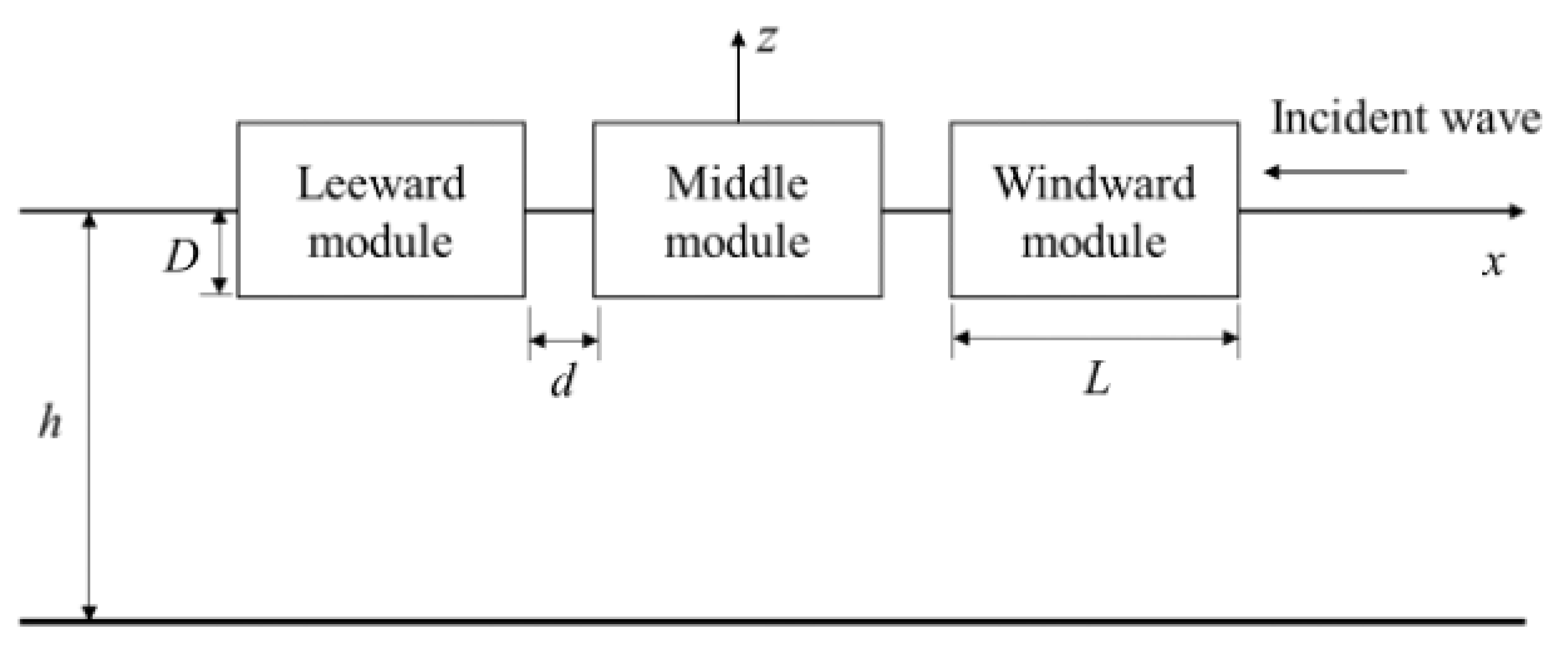
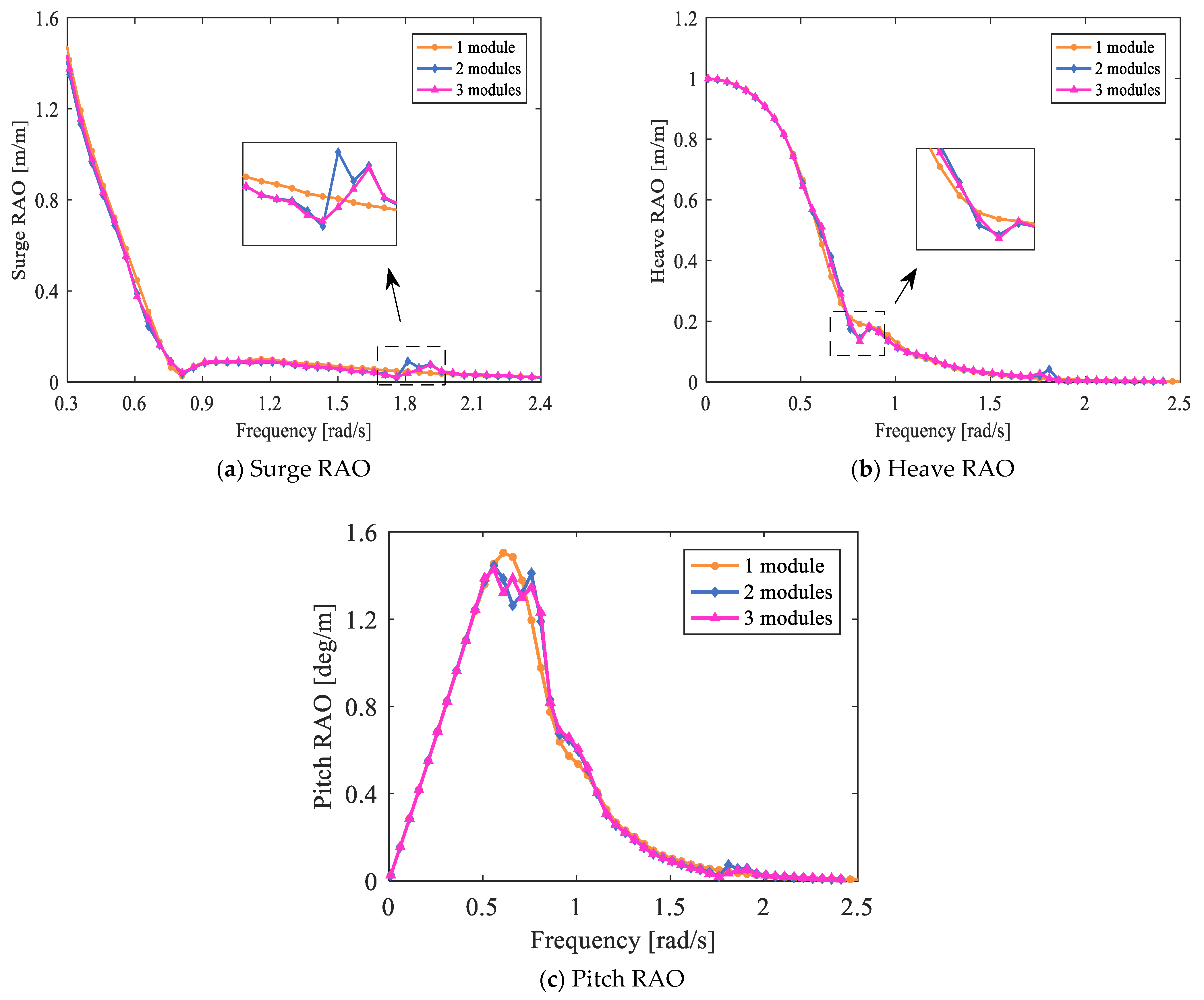
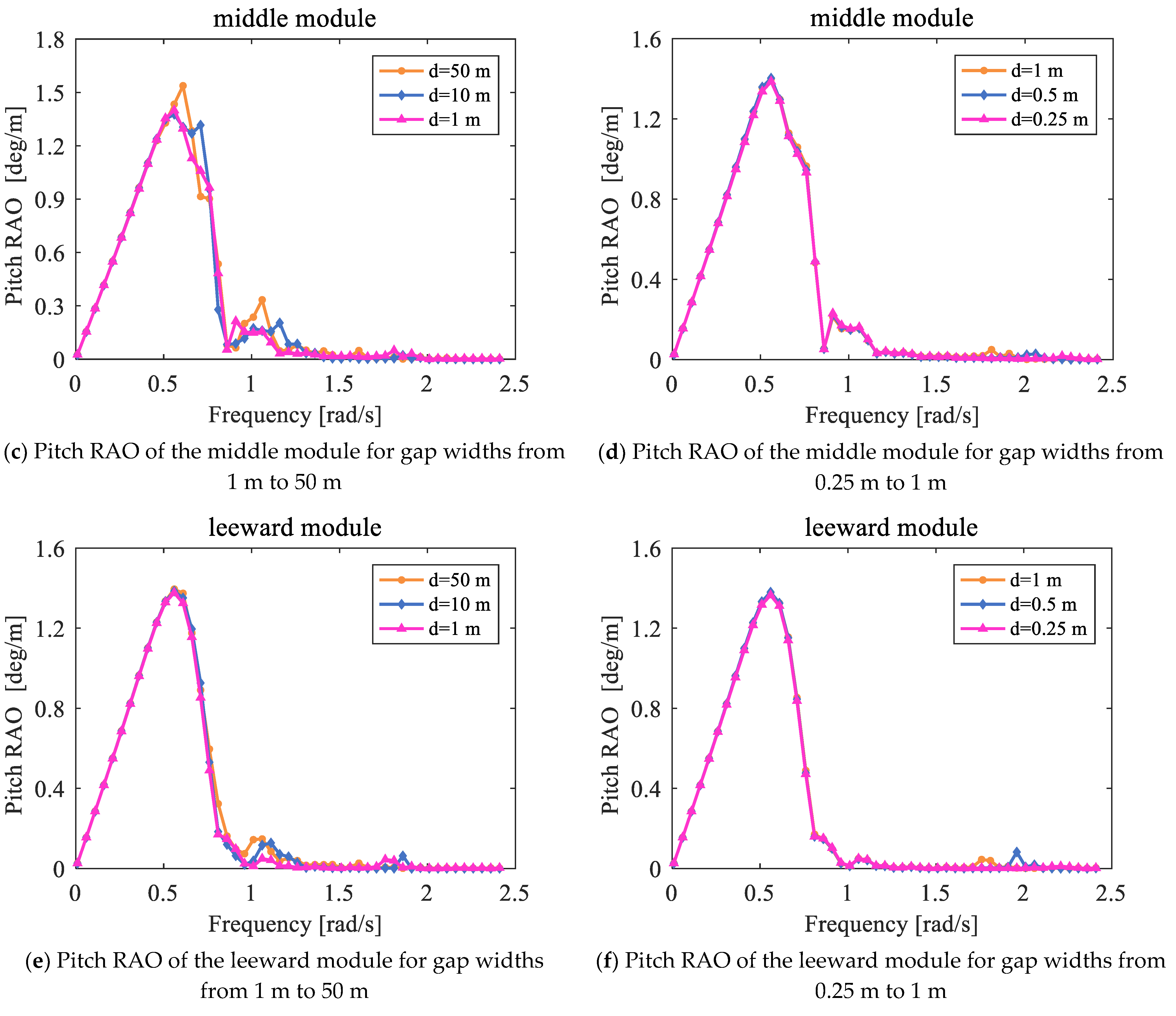
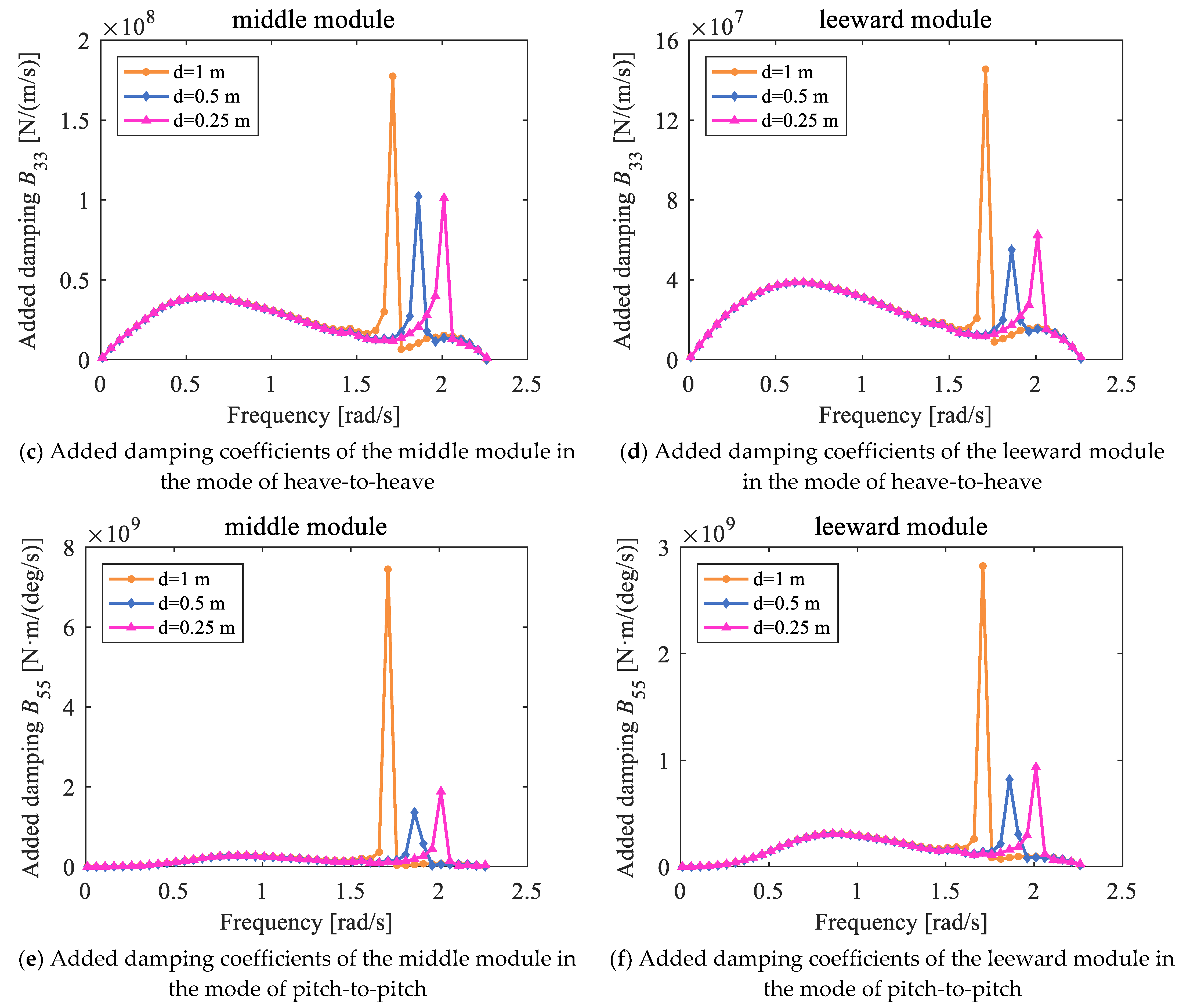
The hydrodynamic interactions between multi-floaters are related to the gap width and the breadth of the module in the series form. With the further decrease of the gap spacing, “pumping mode” replaces “sloshing mode” as the resonance phenomenon in the gap, the water surface in the gap moves in a flat form and the resonance frequency increases continuously under the condition of the same water depth and draft. While the number of modules, by contrast, only affects the motion response in the direction of the pitch in a head sea and has no effect on the resonant frequency.
(2)
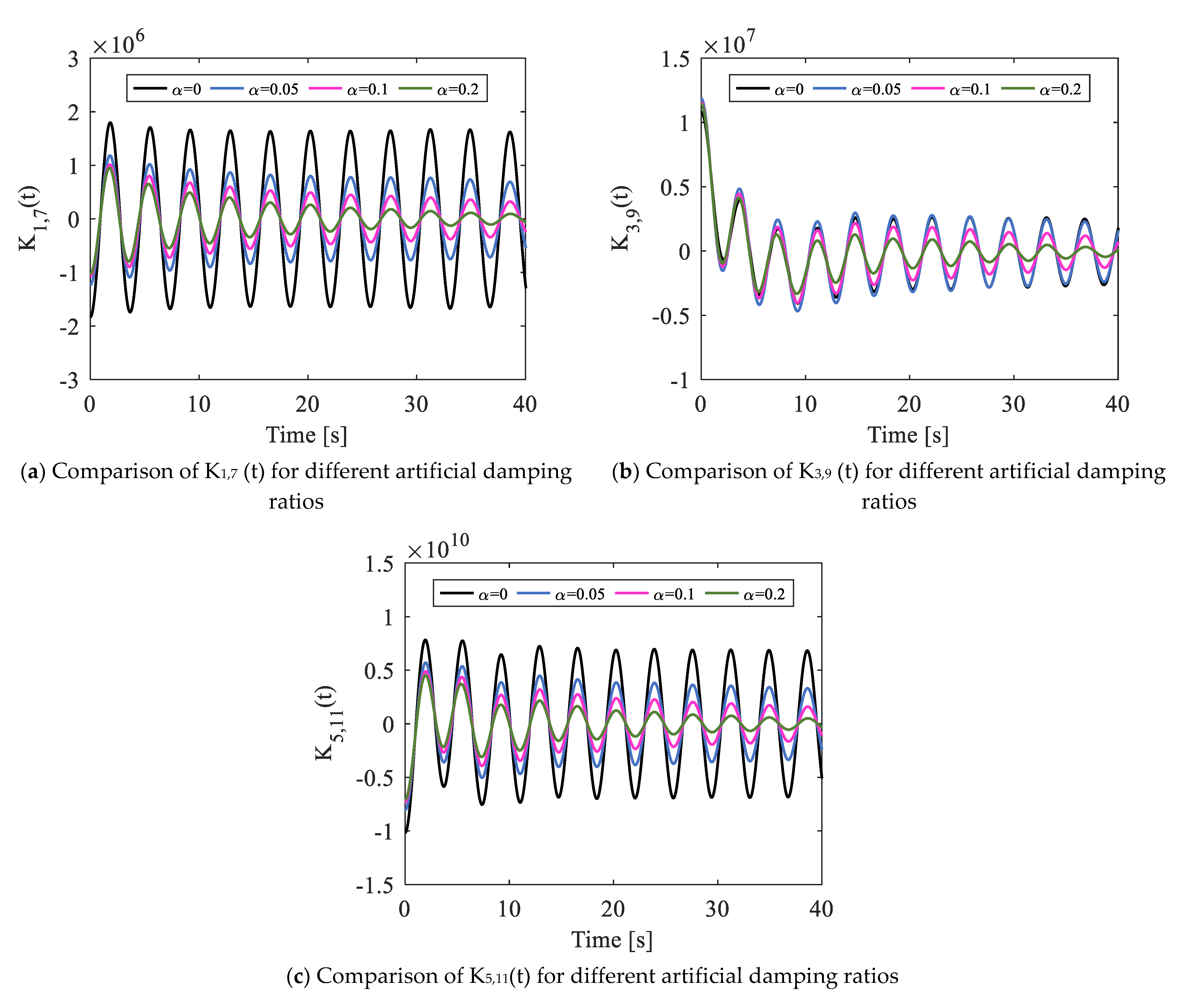
The distorted hydrodynamic coefficients will further cause the impulse response functions in the time-domain equation to be lightly damped, which will lead to errors in calculating time-domain response, making the time-domain results do not agree with those in the frequency domain. Due to this effect, the time-domain model established built upon the frequency-domain results without considering viscosity correction is found to be un-converged.
(3)
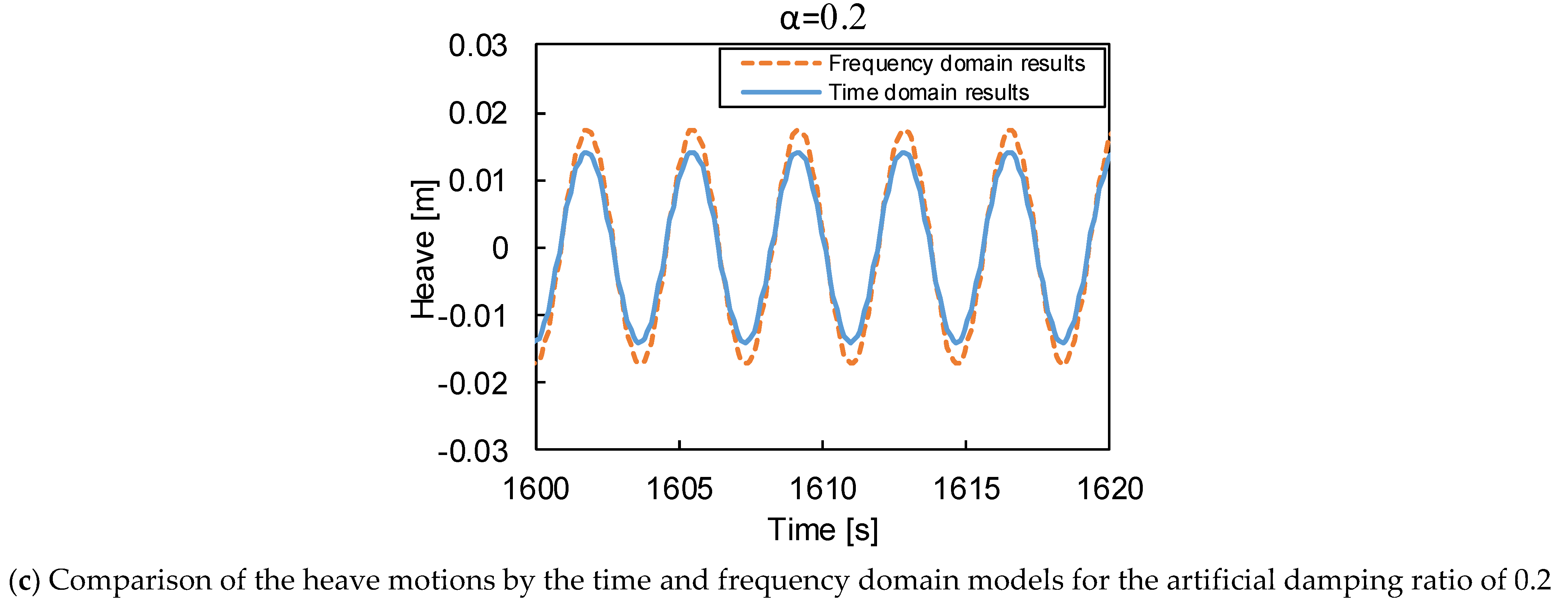
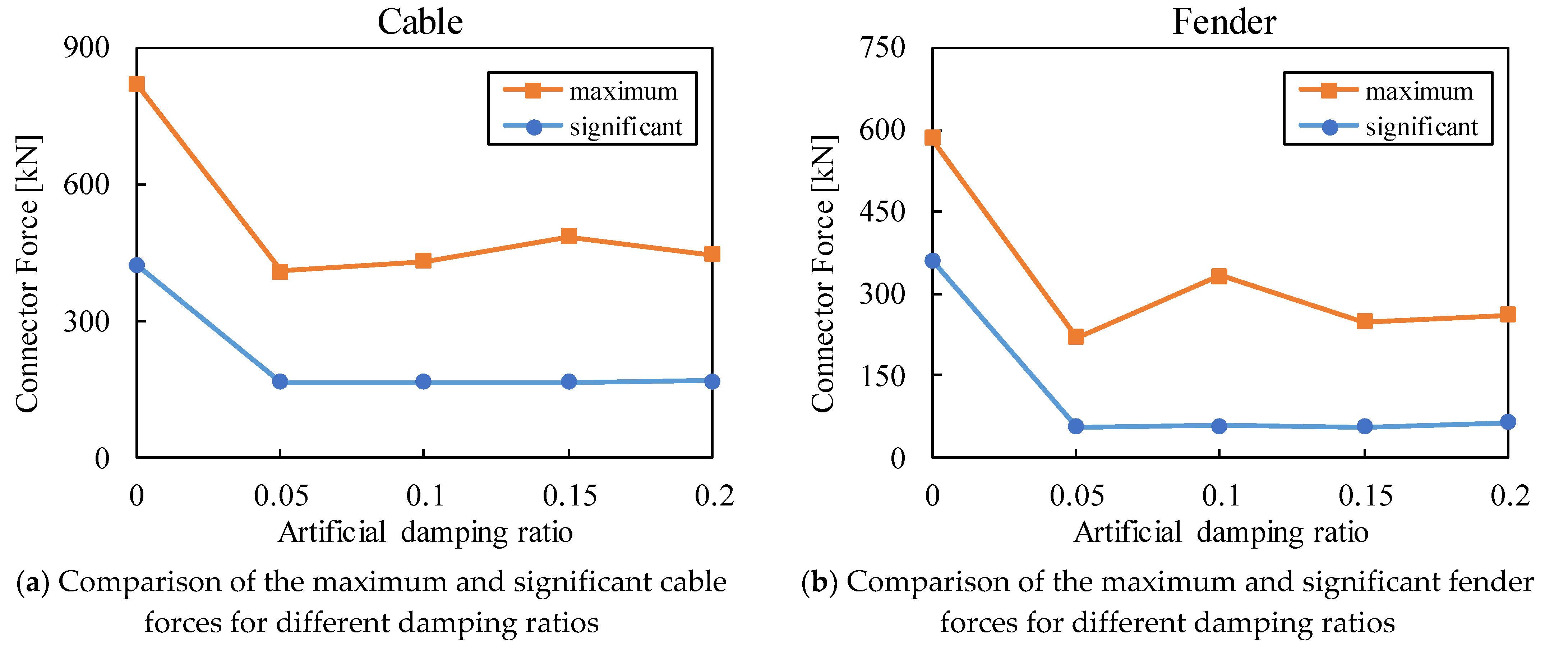
Through the parametric analyses, it is found that the introduction of the artificial damping lid can effectively suppress the unrealistic resonant effects on the hydrodynamic coefficients and impulse response function. Thus, this method can improve the accuracy of both the frequency and time-domain simulations. Specifically, the sharp change of the hydrodynamic coefficients has been lessened by the introduction of the artificial damping lid, which can reduce the added damping coefficient by about 70% at the resonant frequency. This will contribute to the rapid attenuation of the impulse response functions and help to achieve converged time-domain results. Furthermore, this will help to reduce the over-estimated relative motions and connector loads at the resonant frequency based on the RMFC model. For the case of adding an artificial damping ratio of 0.2, the relative heave and pitch motions are found to be reduced by 33% and 50%, respectively. In addition, the maximum cable and fender forces are found to be reduced by 50%, compared with the case without viscosity correction. Nevertheless, there is no significant difference between different artificial damping values on the connector loads and relative motions between adjacent modules.
(4)
It is recommended that one should consider the introduction of artificial damping on the gap fluid to obtain more realistic and accurate time-domain simulations for a multi-module floating system with strong hydrodynamic interactions. This method may have potential applications in the design and dynamic simulation of multi-module floating systems such as the floating airport, floating artificial islands, and marine operations involving multiple ships.
It needs to be noted that this study only provides a preliminary analysis of the artificial damping, the selection of artificial damping value should be determined by either the CFD method or the physical model tests to provide a more accurate simulation of the damping effects of the multi-module system since the hydrodynamic results and impulse response functions has a negligible effect on the hydrodynamics and dynamics. Future studies are recommended to provide a more in-depth analysis into the determination of artificial damping.

Author Contributions

Conceptualization, M.C. and H.G.; methodology, R.T. and H.G.; software, H.G.; validation, M.C., H.G. and N.C.; formal analysis, H.G.; investigation, R.W.; resources, N.C.; data curation, H.G.; writing—original draft preparation, M.C., H.G. and N.C.; writing—review and editing, N.C.; visualization, R.W.; supervision, M.C., R.W. and R.T.; project administration, N.C.; funding acquisition, M.C. All authors have read and agreed to the published version of the manuscript.

Funding

This research was funded by the CCCC Research & Development Project, grant number 2018-ZJKJ-01 and by the National Natural Science Foundation of China, grant number 51809205 and 52171275. The APC was funded by 51809205.

Institutional Review Board Statement

Not applicable.

Informed Consent Statement

Not applicable.

Data Availability Statement

Not applicable.

Acknowledgments

The authors gratefully acknowledge the support by the CCCC Research & Development Project (2018-ZJKJ-01) and by the National Natural Science Foundation of China (Grant No.: 51809205 and 52171275).

Conflicts of Interest

The authors declare no conflict of interest.

References

  1. Tajali, Z.; Shafieefar, M. Hydrodynamic analysis of multi-body floating piers under wave action. Ocean Eng. 2011, 38, 1925–1933. [Google Scholar] [CrossRef]
  2. Mostofi, A.; Bargi, K. New concept in analysis of floating piers for ship berthing impact. Mar. Struct. 2012, 25, 58–70. [Google Scholar] [CrossRef]
  3. Zhang, H.; Xu, D.; Lu, C.; Qi, E.; Hu, J.; Wu, Y. Amplitude death of a multi-module floating airport. Nonlinear Dyn. 2015, 79, 2385–2394. [Google Scholar] [CrossRef]
  4. Zhang, H.; Xu, D.; Xia, S.; Wu, Y. A new concept for the stability design of floating airport with multiple modules. Procedia IUTAM 2017, 22, 221–228. [Google Scholar] [CrossRef]
  5. Zhao, W.; Yang, J.; Hu, Z. Hydrodynamic interaction between FLNG vessel and LNG carrier in side by side configuration. J. Hydrodyn. 2012, 24, 648–657. [Google Scholar] [CrossRef]
  6. Chen, M.; Eatock Taylor, R.; Choo, Y.S. Time domain modelling of the wave induced dynamics of multiple structures in close proximity. In Proceedings of the 2nd Marine Operations Specialty Symposium, Singapore, 16–19 September 2016. [Google Scholar]
  7. Chen, M.; Zou, M.; Zhu, L. Frequency-domain response analysis of adjacent multiple floaters with flexible connections. J. Ship Mech. 2018, 22, 1164–1180. [Google Scholar]
  8. Kim, B.W.; Hong, S.Y.; Kyoung, J.H.; Cho, S.K.; Hong, S. Evaluation of bending moments and shear forces at unit connections of very large floating structures using hydroelastic and rigid body analyses. Ocean Eng. 2007, 34, 1668–1679. [Google Scholar] [CrossRef]
  9. Fu, S.; Moan, T.; Chen, X.; Cui, W. Hydroelastic analysis of flexible floating interconnected structures. Ocean Eng. 2007, 34, 1516–1531. [Google Scholar] [CrossRef]
  10. Gao, R.; Wang, C.; Koh, C. Reducing hydroelastic response of pontoon connector and gill cells. Eng. Struct. 2013, 52, 372–383. [Google Scholar] [CrossRef]
  11. Hong, S.Y.; Kim, J.H.; Cho, S.K.; Choi, Y.R.; Kim, Y.S. Numerical and experimental study on hydrodynamic interaction of side-by-side moored multiple vessels. In Proceedings of the Deepwater Mooring Systems: Concepts, Design, Analysis, and Materials, Houston, TX, USA, 2–3 October 2003; pp. 198–215. [Google Scholar]
  12. Abyn, H.; Islam, M.R.; Maimun, A.; Mahmoudi, A.; Kato, J. Experimental Study of Motions of Two Floating Offshore Structures in Waves. Brodogr. Teor. I Praksa Brodogr. I Pomor. Tehnike. 2016, 67, 1–13. [Google Scholar] [CrossRef] [Green Version]
  13. Miao, G.; Ishida, H.; Saitoh, T. Influence of Gaps between Multiple Floating Bodies on Wave Forces. China Ocean Eng. 2000, 14, 407–422. [Google Scholar]
  14. McIver, P. Complex resonances in the water-wave problem for a floating structure. J. Fluid Mech. 2005, 536, 423–443. [Google Scholar] [CrossRef] [Green Version]
  15. Wang, Y.; Wang, X.; Xu, S.; Wang, L.; Shang, Y. Numerical and Experimental Investigation of Hydrodynamic Interactions of Two VLFS Modules Deployed in Tandem. China Ocean Eng. 2020, 34, 46–55. [Google Scholar] [CrossRef]
  16. Li, Y.; Zhang, C. Analysis of wave resonance in gap between two heaving barges. Ocean Eng. 2016, 117, 210–220. [Google Scholar] [CrossRef]
  17. Newman, J.N. Wave effects on multiple bodies. Hydrodyn. Ship Ocean Eng. 2001, 3, 3–26. [Google Scholar]
  18. Sun, L.; Taylor, R.E.; Taylor, P.H. First-and second-order analysis of resonant waves between adjacent barges. J. Fluid Struct. 2010, 26, 954–978. [Google Scholar] [CrossRef] [Green Version]
  19. Zhu, L.; Zou, M.; Chen, M.; Li, L. Nonlinear dynamic analysis of float-over deck installation for a GBS platform based on a constant parameter time domain model. Ocean Eng. 2021, 235, 109443. [Google Scholar] [CrossRef]
  20. Cummins, W.E.; Iiuhl, W.; Uinm, A. The Impulse Response Function and Ship Motions; David Taylor Model Basin: Washington, DC, USA, 1962. [Google Scholar]
  21. Lawson, M.; Yu, Y.H.; Nelessen, A.; Ruehl, K.; Michelen, C. Implementing nonlinear buoyancy and excitation forces in the wec-sim wave energy converter modeling tool. In International Conference on Offshore Mechanics and Arctic Engineering; American Society of Mechanical Engineers: New York, NY, USA, 2014; Volume 45547, p. V09BT09A043. [Google Scholar]
  22. Cha, J.H.; Ham, S.H.; Lee, K.Y.; Roh, M.I. Application of a topological modelling approach of multi-body system dynamics to simulation of multi-floating cranes in shipyards. Proc. Inst. Mech. Eng. Part K J. Multi Body Dyn. 2010, 224, 365–373. [Google Scholar] [CrossRef]
  23. Kara, F. Multibody Interactions of Floating Bodies with Time-Domain Predictions. J. Waterw. Port Coast. 2020, 146, 04020031. [Google Scholar] [CrossRef]
  24. Lewandowski, E.M. Multi-vessel seakeeping computations with linear potential theory. Ocean Eng. 2008, 35, 1121–1131. [Google Scholar] [CrossRef]
  25. Chen, M.; Eatock Taylor, R.; Choo, Y.S. Time domain modeling of a dynamic impact oscillator under wave excitations. Ocean Eng. 2014, 76, 40–51. [Google Scholar] [CrossRef]
  26. Chen, M.; Eatock Taylor, R.; Choo, Y.S. Investigation of the complex dynamics of float-over deck installation based on a coupled heave-roll-pitch impact model. Ocean Eng. 2017, 137, 262–275. [Google Scholar] [CrossRef]
  27. Feng, X.; Bai, W. Wave resonances in a narrow gap between two barges using fully nonlinear numerical simulation. Appl. Ocean Res. 2015, 50, 119–129. [Google Scholar] [CrossRef]
  28. Yang, M.; Teng, B.; Ning, D.; Shi, Z. Coupled dynamic analysis for wave interaction with a truss spar and its mooring line/riser system in time domain. Ocean Eng. 2012, 39, 72–87. [Google Scholar] [CrossRef]
  29. Koo, B.J.; Kim, M.H. Hydrodynamic interactions and relative motions of two floating platforms with mooring lines in side-by-side offloading operation. Appl. Ocean Res. 2005, 27, 292–310. [Google Scholar] [CrossRef]
  30. Huijsmans, R.H.M.; Pinkster, J.A.; De Wilde, J.J. Diffraction and radiation of waves around side-by-side moored vessels. In The Eleventh International Offshore and Polar Engineering Conference; International Society of Offshore and Polar Engineers: Mountain View, CA, USA, 2001. [Google Scholar]
  31. Faitinsen, O.M. A numerical nonlinear method of sloshing in tanks with two-dimensional flow. J. Ship. Res. 1978, 22, 193–202. [Google Scholar] [CrossRef]
  32. Chen, X.B. Hydrodynamic analysis for offshore LNG terminals. In Proceedings of the 2nd International Workshop on Applied Offshore Hydrodynamics, Rio de Janeiro, Brazil, 14–15 April 2005. [Google Scholar]
  33. Yao, C.; Dong, W. Modeling of fluid resonance in-between two floating structures in close proximity. J. Zhejiang Univ. Sci. A 2015, 16, 987–1000. [Google Scholar] [CrossRef] [Green Version]
  34. Zhao, D.; Hu, Z.; Chen, G. An Investigation on Two-Dimensional Nonlinear Sloshing in Rectangular Tank. In International Conference on Offshore Mechanics and Arctic Engineering; American Society of Mechanical Engineers: New York, NY, USA, 2015; Volume 56475, p. V001T01A045. [Google Scholar]
  35. Zhao, D.; Hu, Z.; Zhou, K.; Chen, G.; Chen, X.; Feng, X. Coupled analysis of integrated dynamic responses of side-by-side offloading FLNG system. Ocean Eng. 2018, 168, 60–82. [Google Scholar] [CrossRef] [Green Version]
  36. Lu, L.; Teng, B.; Cheng, L.; Sun, L.; Chen, X. Modelling of multi-bodies in close proximity under water waves—Fluid resonance in narrow gaps. Sci. China Phys. Mech. 2011, 54, 16–25. [Google Scholar] [CrossRef]
  37. Wang, S.; Wahab, R. Heaving oscillations of twin cylinders in a free surface. J. Ship Res. 1971, 15, 33–48. [Google Scholar]
  38. Newman, J.N. Application of generalized modes for the simulation of free surface patches in multi body hydrodynamics. In Proceedings of the 4th Annual WAMIT Consortium Report, Woods Hole, MA, USA; 2003; pp. 33–69. [Google Scholar]
  39. Moradi, N.; Zhou, T.; Cheng, L. Effect of inlet configuration on wave resonance in the narrow gap of two fixed bodies in close proximity. Ocean Eng. 2015, 103, 88–102. [Google Scholar] [CrossRef]
  40. ANSYS. AQWA Theory Manual; ANSYS, Inc.: Canonsburg, PA, USA, 2013. [Google Scholar]
  41. Ogilvie, T.F. Recent Progress toward the Understanding and Prediction of Ship Motions. In Proceedings of the 5th ONR Symp. on Naval Hydrodynamics, Japan. 1964. Available online: https://ci.nii.ac.jp/naid/20000327176/ (accessed on 9 November 2021).
  42. Kristiansen, E.; Hjulstad, Å.; Egeland, O. State-space representation of radiation forces in time-domain vessel models. Ocean Eng. 2005, 32, 2195–2216. [Google Scholar] [CrossRef]
  43. Greenhow, M. High-and low-frequency asymptotic consequences of the Kramers-Kronig relations. J. Eng. Math. 1986, 20, 293–306. [Google Scholar] [CrossRef]
  44. Cheetham, P.; Du, S.; May, R.; Smith, S. Hydrodynamic analysis of ships side by side in waves. In Proceedings of the International Aerospace CFD Conference, Paris, France, 18–19 June 2007. [Google Scholar]
  45. Xu, X.; Yang, J.; Li, X.; Xu, L. Time-domain simulation for coupled motions of three barges moored side-by-side in float-over operation. China Ocean Eng. 2015, 29, 155–168. [Google Scholar] [CrossRef]
Figure 1. Sketch of the multi-module system.
Jmse 09 01256 g001
Figure 2. Simulation of RMFC model in AQWA.
Jmse 09 01256 g002
Figure 3. Plan view of three configurations (a) 1 module, (b) 2 modules, (c) 3 modules.
Jmse 09 01256 g003
Figure 4. RAOs of the windward module in the case that the number of floating bodies is 1, 2, and 3 respectively (wave angle = 180°).
Jmse 09 01256 g004
Figure 5. Comparison of the windward module hydrodynamic results with the change of the number of floating bodies (wave angle = 180°).
Jmse 09 01256 g005
Figure 6. Pitch RAOs of 3-module model in the head sea with different gap widths.
Jmse 09 01256 g006aJmse 09 01256 g006b
Figure 7. Comparison between the windward module hydrodynamic coefficients of the 3-module model with different gap widths.
Jmse 09 01256 g007
Figure 8. Damping term of two different modules in the 3-module model with different gap widths.
Jmse 09 01256 g008aJmse 09 01256 g008b
Figure 9. Windward module hydrodynamic coefficients with different artificial damping ratios, α , in 3- module model.
Jmse 09 01256 g009aJmse 09 01256 g009b
Figure 10. Free surface elevation in the front gap under different artificial damping ratios.
Jmse 09 01256 g010
Figure 11. Free surface elevation in the back gap under different artificial damping ratios.
Jmse 09 01256 g011
Figure 12. Comparison of the calculated impulse response function K(t) for the windward module with different module numbers.
Jmse 09 01256 g012
Figure 13. Comparison of the calculated impulse response function K(t) for the windward module of the 3-module model with different artificial damping ratios, α.
Jmse 09 01256 g013aJmse 09 01256 g013b
Figure 14. Comparison of the off-diagonal calculated impulse response function K1,7, K3,9, and K5,11 between the windward module and middle module of the 3-module model.
Jmse 09 01256 g014
Figure 15. Comparison of the off-diagonal calculated impulse response functions K1,13, K3,15, and K5,17 between the windward module and rear module of the 3-module model.
Jmse 09 01256 g015
Figure 16. Comparison of windward module heave motions between frequency-domain results and time-domain results subjected to the regular wave (H = 1 m, ω = 1.7 rad/s, α = 0).
Jmse 09 01256 g016
Figure 17. Heave response of the windward module in the frequency domain and time domain under different artificial damping α subjected to the regular wave (H = 1 m, ω = 1.7 rad/s).
Jmse 09 01256 g017aJmse 09 01256 g017b
Figure 18. Comparison of windward module pitch motions between frequency-domain results and time-domain results subjected to the regular wave (H = 1 m, ω = 1.7 rad/s, α = 0).
Jmse 09 01256 g018
Figure 19. Pitch response of the windward module in the frequency domain and time domain under different artificial damping α subjected to the regular wave (H = 1 m, ω = 1.7 rad/s).
Jmse 09 01256 g019
Figure 20. Layout of the mooring system for the 3-module model.
Jmse 09 01256 g020
Figure 21. Time-domain responses under two irregular waves.
Jmse 09 01256 g021aJmse 09 01256 g021b
Figure 22. The statistical results of time-domain response, Tp = 3.7 s. (maximum: the maximum value of the three-hour calculation; significant: 1/3 of the results in three hours).
Jmse 09 01256 g022
Figure 23. The statistical results of connector load for RMFC model (Tp = 3.7 s).
Jmse 09 01256 g023
Table 1. Parameters of single module.
Module CharacteristicValue
Length (m)100
Breadth (m)50
Depth (m)5
Centre of gravity above base, KG (m)2.5
Draught (m)2
Radius of roll gyration, Rxx (m)14.5
Radius of pitch gyration, Ryy (m)28.9
Radius of yaw gyration, Rzz (m)32.27
Table 2. Resonance frequency calculated by Equation (5) and numerically.
Gap Width(m)ω Calculated by
Equation (5)
ω Calculated in
AQWA
11.791.71
0.51.971.86
0.252.082.01
Publisher’s Note: MDPI stays neutral with regard to jurisdictional claims in published maps and institutional affiliations.

