Article

Effects of the Installation Method, Loading Condition, and Failure Mechanism on the Behavior of Suction Piles under Monotonic Horizontal Loading

1
Inftra Safety Research Center, Korea Institute of Civil Engineering and Building Technology, Goyang 10223, Korea
2
Department of Ocean Civil Engineering, Gyeongsang National University, Tongyeoung 53064, Korea
*
Author to whom correspondence should be addressed.
J. Mar. Sci. Eng. 2021, 9(12), 1333; https://0-doi-org.brum.beds.ac.uk/10.3390/jmse9121333
Submission received: 10 October 2021 / Revised: 8 November 2021 / Accepted: 24 November 2021 / Published: 26 November 2021
(This article belongs to the Section Ocean Engineering)

Abstract

:
A suction pile is a promising option when floating offshore structures are deployed at deep and distant locations. A suction pile is typically used for the foundation system of a mooring system subjected to horizontal loading with a load inclination. In this study, the effects of installation method, loading position, and load inclination on the behavior of a suction pile under monotonic horizontal loading were evaluated via large-scale soil chamber testing. A series of horizontal load tests were performed by varying the loading position at pile embedded lengths of 1/4, 1/2, 2/3, and 3/4. A horizontal load test with a load inclination of 20° was conducted and compared with that of a load inclination of 0°. The failure mechanism of the suction piles under monotonic horizontal loading was assessed via particle image velocimetry (PIV) analysis. The movement of the suction pile during monotonic horizontal loading was elucidated in terms of the horizontal displacement, vertical displacement, and rotation angle. The results of this study show apparent differences between jacking and suction-installed piles and piles under different loading conditions. The PIV analysis shows that the rotational behavior under monotonic horizontal loading can be a critical point to affect the horizontal resistance of the suction pile.

1. Introduction

Several types of offshore foundation systems exist to support superstructures or floating structures. For the zone near the shoreline (e.g., ~50 m deep), a direct foundation system, such as a gravity base, a monopile (with guy wires), a tripod, and jacket foundations, can be used for offshore structures [1]. As the distance from the shoreline and water depth increase (up to 1600 m deep), the offshore foundation system transitions to an indirect foundation with a mooring system, for example, with a dead weight, driven pile, drag anchor, suction pile, torpedo pile, vertically loaded anchor, etc. [2].
Among the indirect foundations for the mooring system, suction pile is an offshore foundation system that is widely used worldwide; in fact, it is also known as bucket foundation, skirted foundation, suction anchor, suction caisson, etc. [3]. The suction pile uses suction to install a bucket-type pile. The pile is descended to the target area by gravity. Subsequently, the tubing connected to the top of the pile draws water from the inside pile and the pressure inside the pile becomes negative. The differential pressure induced by the suction between the inside and outside piles enables the pile to penetrate the ground until an equilibrium state is achieved (e.g., penetrating force = penetration resistance) [4]. Suction piles offer many advantages compared to other types of anchors, such as easy positioning in deep water, easy removal and relocation, less dependency on heavy installation machinery, use of large-diameter piles that can develop considerable resistance to external forces, etc. [5].
Since the study by Goodman et al. [6], numerous studies pertaining to suction piles have been conducted [7,8,9,10,11]. A suction pile is a bucket-type pile installed using suction; however, in many cases, in laboratory conditions, jacking pressure is applied when installing the bucket pile due to difficulties in using suction pressure in a laboratory [12]. It is well known that seepage flow significantly affects the installation of suction piles, as induced suction loosens the soil inside and at the tip of the pile [13]. Therefore, the horizontal resistance of the suction pile is affected by the installation method (i.e., the jacking pressure or suction pressure).
As a foundation moored for floating structures, a suction pile is typically subjected to horizontal loading. The horizontal behavior of suction piles has been investigated consistently for both monotonic and cyclic loadings [14,15,16,17,18,19]. The loading position can alter the horizontal behavior of suction. Different loading positions may induce different failure modes in the foundation system under horizontal loading. The failure mechanism of the suction pile under different loading conditions can provide a better understanding of the horizontal behavior of the suction pile. However, a clear explanation is yet to be presented.
The aim of this study is to examine the horizontal behavior of suction piles under monotonic loading. The effects of different installation methods (e.g., jacking pressure and suction pressure), loading conditions (e.g., loading at different locations, as well as horizontal and inclined loadings), and failure modes of the suction pile under horizontal loading via the particle image velocimetry (PIV) of suction piles in sand were investigated. A large-scale soil box measuring 1 m in width, 2 m in length, and 1.5 m in height was used. A model pile was installed using jacking pressure and suction pressure separately and then tested. A series of horizontal load tests were conducted on the suction piles (installed via suction pressure) based on various loading positions and loading angles. The horizontal behavior of the suction piles was analyzed with comprehensive approaches using PIV.

2. Materials and Methods

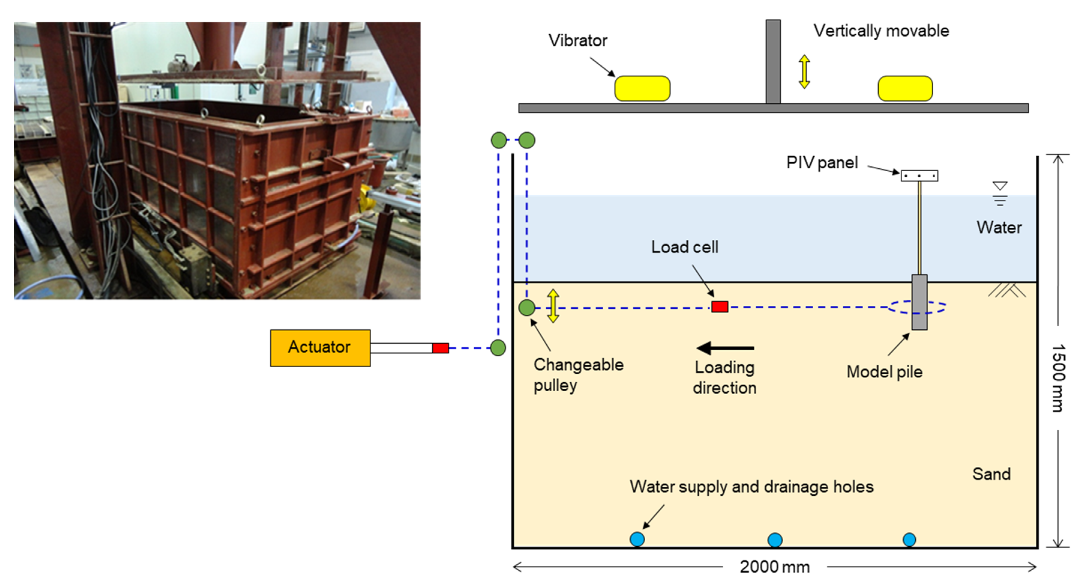
2.1. Soil Chamber and Soil Preparation

A large-scale soil chamber was used, as illustrated in Figure 1. The chamber comprised of 17–22 mm thick steel plates. The chamber measured 2 m (length) × 1 m (width) 1.5 m × (height). Several pipes and holes were installed at the bottom of the chamber to supply water to and drain water from the inside chamber. A porous ceramic filter was placed at the hole to prevent sand from entering. An actuator (Bongshin Co., Osan-si, Korea) was installed outside the chamber to apply horizontal loading to the model pile. The actuator was connected to a changeable pully attached to the side of the chamber such that the loading position can be easily changed. A load cell was placed on the wire near the testing spot; therefore, the effect of the pulley was disregarded and the actual horizontal resistance was measured. Specific information regarding the horizontal load system can be found in [20].
Figure 2 illustrates the process for the soil box preparation. A pre-embedded wire was used for the horizontal loading. First, the sand was placed into the chamber. When the sand height level was near the target loading position, the pulley was relocated to the same location as the target loading position; subsequently, a noose knot was placed on the sand surface (Figure 2a). Additional sand was placed at the final height (Figure 2b). The model pile was installed where the noose knot was installed (Figure 2c). During the initial phase of the test, the horizontal resistance was approximately zero; however, it began to increase once the wire converged with the model pile (Figure 2d). When the PIV panel began to move, the total (or horizontal) displacement (δ) was assumed to be initiated. By truncating the initial dragging displacement based on the PIV analysis, the pure horizontal behavior of the model pile was achieved.
The height of the sand was maintained constant (~1 m). After placing the sand, the vibrating plate installed above the soil chamber was moved down onto the sand surface (Figure 1). Vibrators (EXEN Co., Japan) attached on the plate induced a dynamic load for 1 min. After completing the vibration, the plate returned to its original position. Post-measurement indicated that the relative density (Dr) of the sand was ~70% in general. Therefore, the preparation procedure guaranteed the repeatability of this study.
The Joomunjin standard sand was used in this study. The sand has a specific gravity of 2.62, a mean particle size of 0.57 mm, minimum and maximum void ratios of 0.63 and 0.92, respectively, a uniformity coefficient of 1.5, and a curvature coefficient of 1.0 [21,22,23]. The united soil classification system indicates poorly graded sand [24]. Based on the shear responses of consolidated and drained triaxial testing under confining stresses of 50, 100, and 200 kPa [25], the drained internal friction angle (ϕ’) of Dr = 70% sand was determined to be 37.5° with a cohesion of 0 kPa.

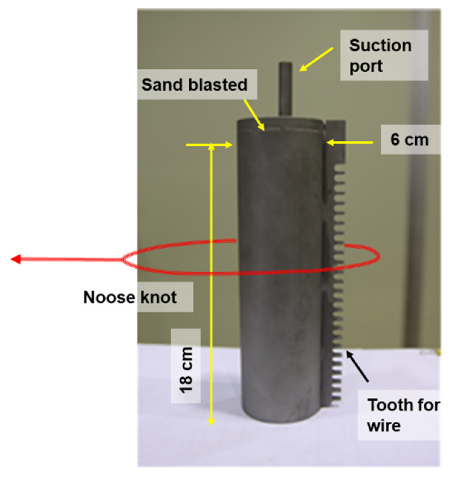
2.2. Model Suction Pile

Three aspects were considered when manufacturing the model suction pile: the boundary and scale effects, horizontal loading, and suction. A pile diameter (D) of 6 cm was determined considering the horizontal boundary to the chamber wall (e.g., a distance exceeding 8D from the pile to the wall allows the boundary effect in the horizontal direction to be disregarded [26]). A pile length (L) of 18 cm was selected to avoid the effect of the boundary on the depth [27]. Therefore, the aspect ratio of the pile (L/D) was 3. The horizontal behavior of the pile embedded in the ground was significantly affected by the surface roughness of the pile [28,29]. The average surface roughness of the materials (Ra) can be correlated with the mean particle size (D50) as the relative surface roughness (Rn), i.e., Ra/D50 [30,31]. Based on the suction pile in the field (Rn 0.229) [32], the model pile surface was sandblasted and Rn was calculated to be 0.211–0.263.
The thickness of the pile was 1.2 mm. Due to laboratory limitations, the model pile had to be connected to a noose knot. However, during horizontal loading, the wire that simply contacted the pile slipped along the pile surface and provided unreliable results. To overcome the slip of the wire, small teeth were created along the pile at the opposite side of the loading direction (Figure 3). The teeth plate measured 1 cm thick, 5 mm wide, and 7.5 mm long. The noose knot location is dependent on the embedment depth and loading conditions (e.g., horizontal or inclined loading) with installation uncertainties, thus several trials were necessitated to achieve the target loading position.
A suction port was installed at the pile cap. The cap was 30 mm thick. The suction port was connected to a peristaltic pump to control the suction rate. The suction installation method is discussed in the following section.

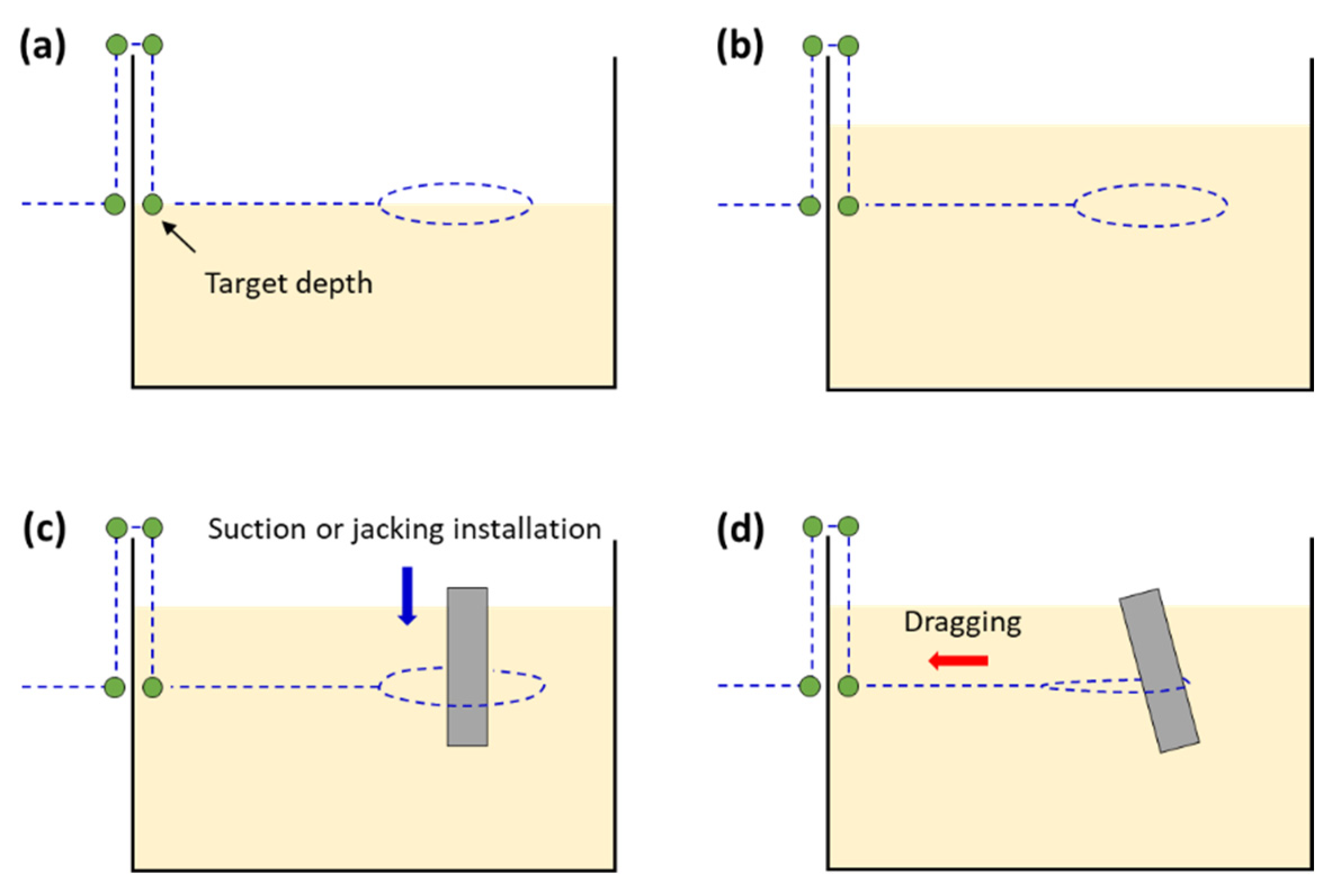
2.3. Pile Installation Methods

All model piles were installed where the center of the noose knot was embedded. Two different installation pressures were used: jacking pressure and suction pressure. For the jacking installation, the model pile was placed at the target position (i.e., the sand surface at the expected zone of the noose knot). Subsequently, the cap of the pile was pressed by the overhead vibrating plate until a pile embedment depth of 18 cm was achieved. The suction installation was uneasy to normalize and systemize the suction pressure. When the suction was too low, the model pile penetrated with insufficient depth. By contrast, boiling and heaving sands were observed inside the model pile when the suction was too high. Therefore, by controlling the peristaltic pump, the model pile was installed via suction to the target depth (18 cm). A pumping rate ranging from 1 to 10 cm3/s was applied during the suction installation. The loading position for the jacking-and suction-installed piles was 2/3 of the length of the pile (i.e., 0.67L). The suction port was removed to install the PIV panel.
In addition to the horizontal load tests, cone penetration testing (CPT) was performed to evaluate the penetration resistance of pre-tested sands inside and outside the piles. A miniature cone penetrometer with a diameter of 12 mm and a cone angle of 60° was used to measure the penetration resistance via micro-strain gauges attached to the inner cone (ABest Co., Seoul, Korea). The penetrometer was connected to a speed-controllable actuator fixed to the soil chamber. The penetration rate was maintained at 1 cm/min. CPT was performed approximately 2 h after installing the pile.

2.4. Particle Image Velocimetry

Particle image velocimetry (PIV) was performed in this study to obtain a more comprehensive understanding of the horizontal behavior of a suction pile. PIV is an optical analysis method that coordinates an object with strain or time [33]. The PIV panel was attached to the cap of the pile as shown in Figure 1 and the mechanism of the PIV analysis performed in this study is illustrated in Figure 4. As the pile was submerged, a rod was connected to the PIV panel and model pile. A camera was installed in front of the soil chamber. Photographs were captured at different time points during the test. The images captured were image processed and then transformed into binary images (e.g., black and white). Using the position information of the black dot in the PIV panel, actual coordinates with respect to the pile cap (e.g., x, y, and θ) were calculated (this is known as the “particle tracking method”; Figure 4). Finally, each coordinate was correlated with the records of the horizontal load testing in the comparisons between the time information for the horizontal displacements and photographs. Based on the original point at the pile cap, sign conventions of positive for the x-coordinate toward the loading direction, positive for the y-coordinate upward, and positive for the θ-coordinate toward the loading direction (i.e., counterclockwise in Figure 1) were used.

2.5. Test Program

A series of horizontal load tests were performed. Details regarding the test program are listed in Table 1. Four specific loading positions were first selected, i.e., 1/4L, 2/4L, and 3/4L from the top of the sand surface (e.g., normalized length 0.25L indicates that the loading position is 4.5 cm below the sand surface). Andersen et al. [34] and Band et al. [35] reported that the maximum horizontal resistance occurred at an embedment depth of 55–80%. Therefore, the loading position of 0.67L (i.e., 2/3L) was considered in addition to the quarterly positions. In regard to the catenary mooring system, a load inclination range of 0°–20° (horizontal angle) was observed [36]. Hence, most load tests were performed with a load inclination (α) of 0° (horizontal to vertical) and one test was performed with α = 20° at 0.67L. A setup was installed via the jacking pressure (J) and loaded at 0.67L with α = 0°. This setup was compared to the installed setup via suction pressure with the same loading position and angle. The notation of “installation method/loading position/load inclination” is used herein. For example, “S0.67L-20” indicates installed by suction (S) and loaded at 0.67L (0.67L) at a load inclination of α = 20° (20). The loading tests were conducted for at least two h after installing the model pile to eliminate any induced pore water pressure. Horizontal loading was applied at a loading rate of 100 mm/min, followed by the procedure proposed by [37] and [35]. The obtained data were filtered to eliminate the noise captured during the tests. PIV analysis was conducted for cases S0.25L-0, S0.67L-0, and S0.75L-0.

3. Results

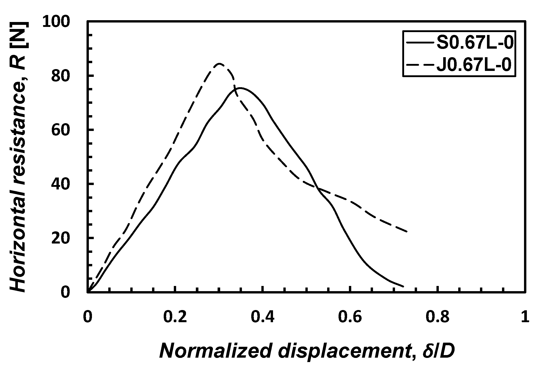
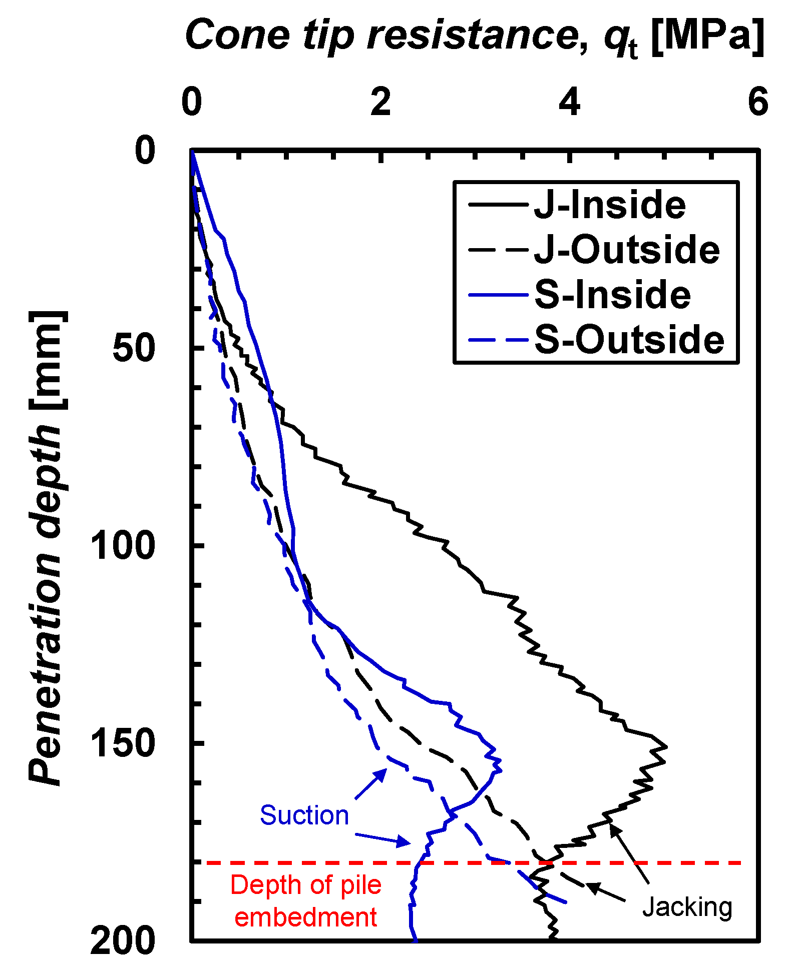
3.1. Effect of Installation Method

Horizontal load tests on the piles installed by jacking and suction pressures were performed and the results are plotted in Figure 5. The horizontal displacement (δ) was normalized to the pile diameter (i.e., δ/D). In general, the jacking-installed pile (J0.67L-0) exhibited higher responses than the suction-installed pile (S0.67L-0). The initial reaction modulus, R/δ, where R measured the horizontal resistance of the jacking and suction-installed piles, was 5.8 and 4.5 kN/m, respectively. Meanwhile, the peak horizontal resistance (Rpeak) was 84.3 and 75.4 N for the jacking and suction-installed piles, respectively.
The cone penetration characteristics of the pre-tested sands near the zone of piles installed via jacking and suction were comparatively evaluated. Two CPTs were performed at the center of the installed piles (denoted as “inside”), whereas the other two were implemented at a 1D distance from the piles (denoted as “outside”). For the 1D distance, it was assumed that the zone was affected by induced seepage and that no boundary effect was imposed by the miniature cone penetrometer [38]. Figure 6 shows the cone tip resistance (qt) along the penetration depth. The measured values indicate that the value inside the pile was higher because of the constraint condition by the pile wall (e.g., pile diameter = 60 mm and cone diameter = 12 mm). The qt for the inside jacking-installed pile (J-Inside) increased to ~5 MPa until a penetration depth of ~150 mm and then decreased. The decrease in qt was due to the stress release when the cone tip was near the pile point. The qt measured outside the jacking-installed pile (J-Outside) increased gradually with the penetration depth. The suction-installed pile exhibited a lower qt but a similar trend to that of the jacking-installed pile. The maximum qt = ~3 MPa (S-Inside) was observed at a penetration depth of ~150 mm. The qt for S-Outside was similar to that of J-Outside but slightly lower. When suction was applied from the inside of the pile, both downward and upward seepage were induced in the surrounding soil. When the upward seepage exceeded the critical condition of the soil, a quick condition occurred. The CPT results imply that the sands inside the suction-installed pile were loosened primarily by suction as compared to the jacking-installed pile. The loosening of soils inside the pile resulted in a reduced penetration resistance of the suction pile [39]. The CPT results revealed that the zone near the pile point was subjected to disturbance by suction. Moreover, the horizontal behaviors of the jacking and suction-installed piles were different. Therefore, it was concluded that the shearing characteristics of the sands and piles differed based on the installation method and hence should be considered in the analysis.

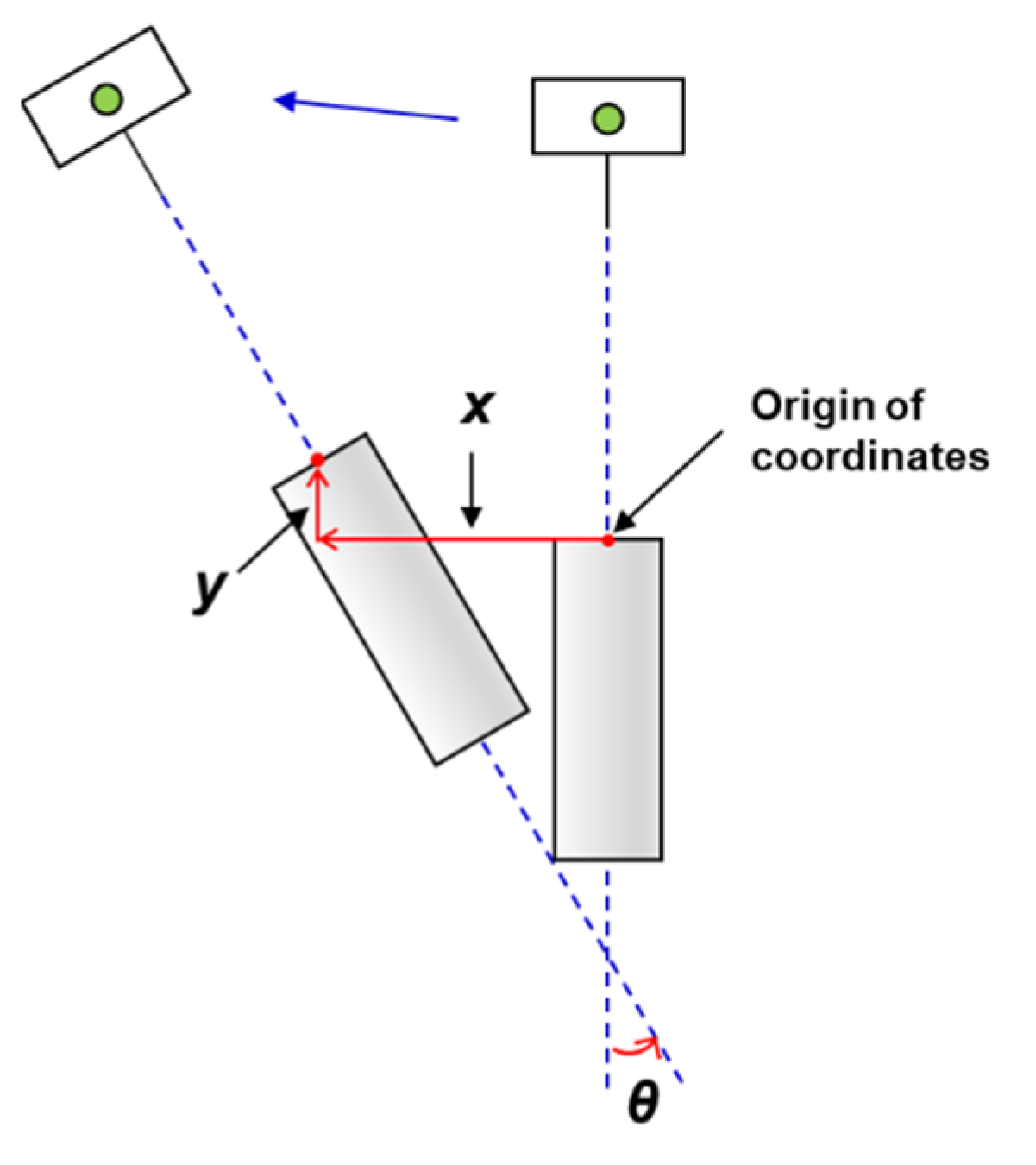
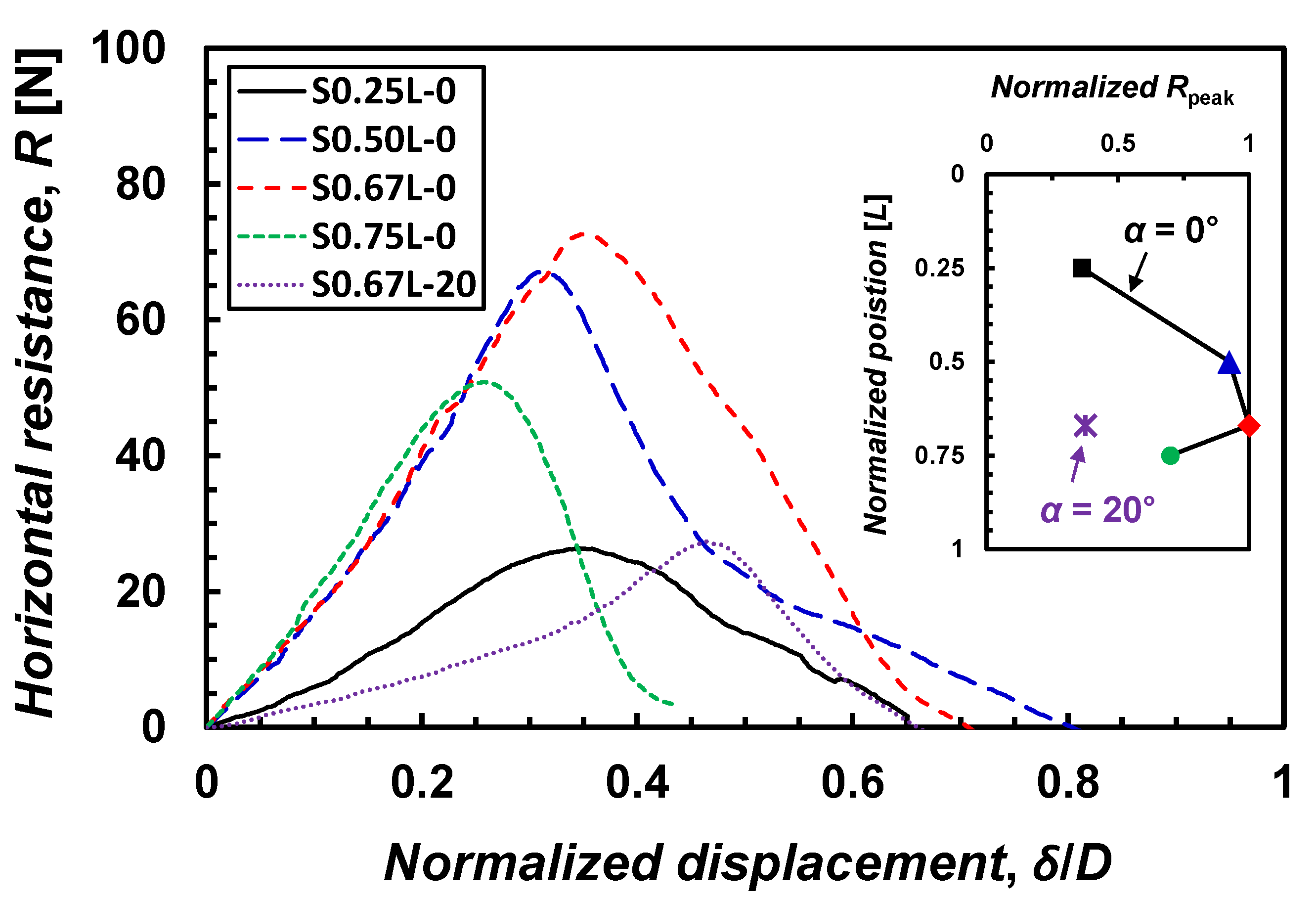
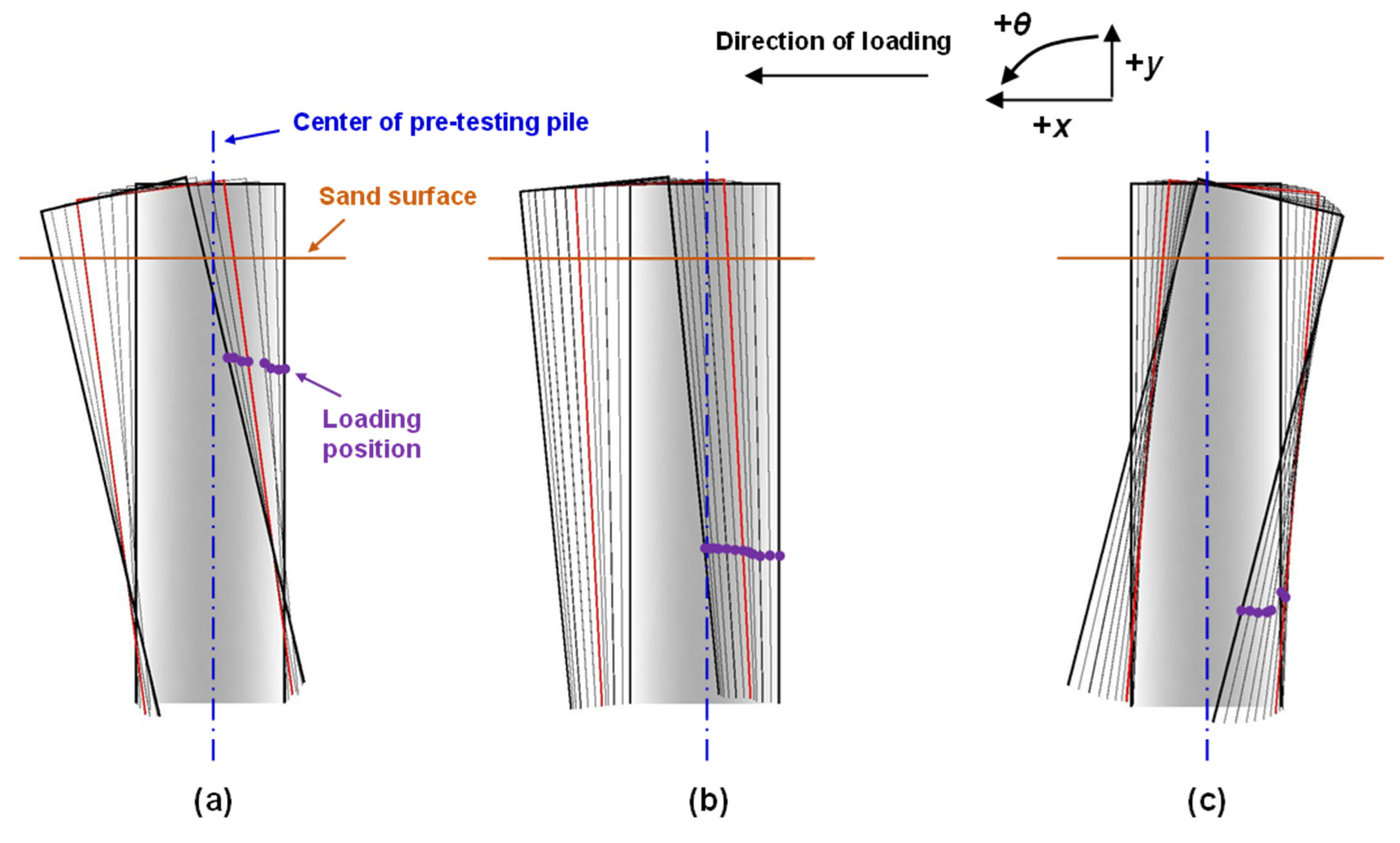
3.2. Effect of Loading Position and Inclination

The horizontal behaviors of the suction-installed piles varied with the loading positions and inclination, as shown in Figure 7. In general, the horizontal resistance gradually increased with the displacement. The initial modulus of S0.25L-0 was ~1.7 kN/m, whereas the initial reaction modulus for loading positions 0.50L, 0.67L, and 0.75L were ~4.5 kN/m. Meanwhile, the Rpeak differed based on the loading position. The Rpeak increased in the order of S0.75L-0, S0.50L-0, and S0.67L-0. The δ/D at Rpeak showed the same order to the order of Rpeak. The maximum Rpeak was observed at the loading position of 0.67L, which is consistent with the observations of [34] and [35]. The inset in Figure 7 shows the normalized Rpeak with respect to the Rpeak of S0.67L-0 (Rpeak(max)) as a function of the loading position. The Rpeak of S0.25L-0, S0.50L-0, and S0.75L-0 was 36%, 92%, and 70% of Rpeak(max), respectively. After the peak resistance appeared, the horizontal resistance softened as the displacement increased.
The horizontal behavior of the suction pile with a loading position of 0.67L and a load inclination of 20° (S0.67L-20) indicated a lower initial reaction modulus and lower peak horizontal resistance than the identical case, albeit with a load inclination of 0° (S0.67L-0). The initial behavior of S0.67L-20 was reflected by a binary line representing reaction moduli of ~0.8 and ~3.0 kN/m. The Rpeak was 38% of Rpeak(max). Considering the failure wedge angle (ξ) under horizontally loaded conditions, i.e., ξ = 45° + ϕ’/2 [40], where ϕ’ = 37.5°, the horizontal angle of ξ (i.e., 90° − ξ) was 26.3°. The loading condition of α = 20° may induce a critical condition for the failure of the pile from the beginning, causing a rapid yield, as shown in Figure 7. The level of the load inclination varied based on the mooring system. Therefore, a careful analysis is required when an inclined load is considered in the design.

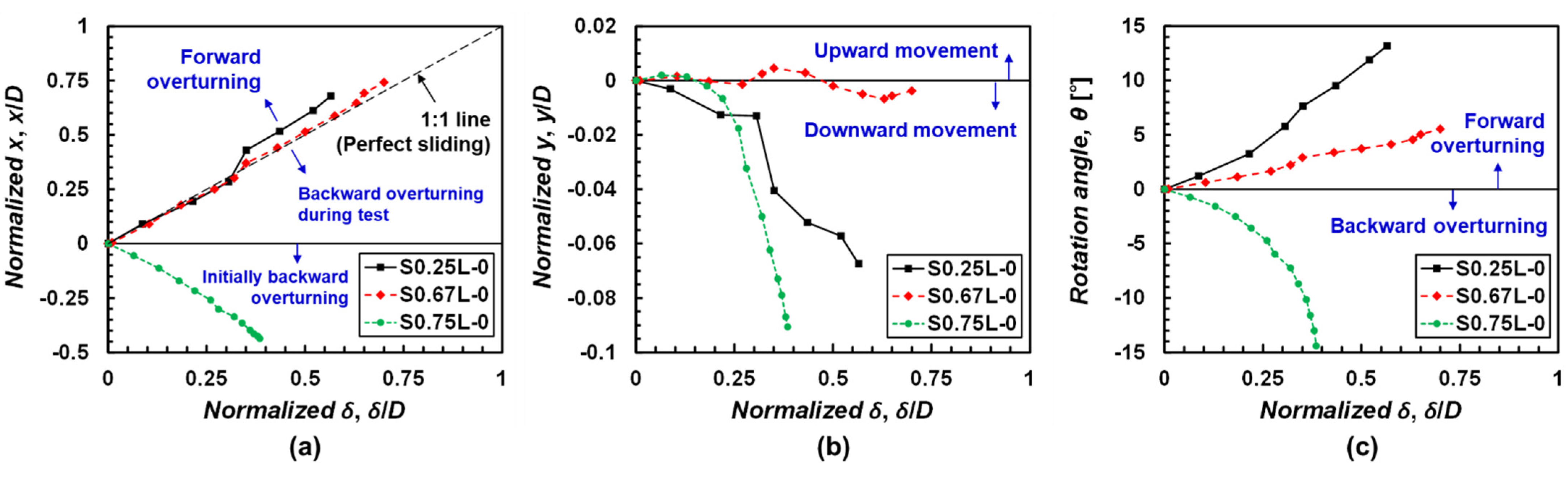
3.3. Failure Mechanism under Horizontal Loading

The mechanical behavior can reveal the stress–strain relationship of the target (Figure 5, Figure 6 and Figure 7); however, a different approach is required to understand the actual failure mechanism. The PIV analysis enabled us to understand the failure mode in this study. Figure 8 shows the pure horizontal displacement (x), vertical displacement (y), and rotation angle (θ) at the center of the pile cap with the corresponding δ during the horizontal load testing; x and y were normalized by the pile diameter (D). It is noteworthy that the x from the PIV analysis differed slightly from δ. The δ includes all mechanically measured horizontal displacements within the system, whereas x is the pure horizontal displacement of the pile cap measured via PIV analysis. Figure 9 shows the sequential movements of the suction pile during testing based on the calculated (x, y, and θ).
Figure 8 provides a quantitative understanding of the failure mechanism of the suction pile under horizontal loading, whereas Figure 9 presents the qualitative and instantaneous behavior of the suction pile. Figure 8a shows x based on δ. When x is equal to δ (i.e., 1:1 line in Figure 8a), the pile perfectly slides without overturning. The x value of S0.67L-0 was consistent with that of the 1:1 line in the entire range of measurements. The x of S0.25L-0 was consistent with the 1:1 line up to ~0.3 δ/D but indicated values exceeding those of the 1:1 line. When x/D exceeded δ/D, the pile cap was located ahead of the pile loading position, which resulted in forward overturns. The x value of S0.75L-0 was negative from the beginning. Negative values of x/D from the beginning imply that the pile overturned backwardly from the beginning. Figure 8c and Figure 9 provide more explanations regarding these observations. The case of S0.25L-0 indicated an overturn towards the loading direction (Figure 8c and Figure 9a). The rapid increase in the rotation angle appeared to have contributed to the low horizontal resistance of the pile. By contrast, the case of S0.75L-0 indicated an overturn opposite to the loading direction (Figure 8a,c and Figure 9c). The slope of θ for S0.75L-0 increased as displacement occurred. However, the Rpeak of S0.75L-0 was higher than that of S0.25L-0 (Figure 7). It may be speculated that forward overturning induced a lower horizontal resistance compared to backward overturning in this study. The vertical movements (y) of S0.25L-0 and S0.75L-0 supported the overturning behavior of the suction piles.
The x of S0.67L-0 was consistent with the 1:1 line (Figure 8a); moreover, y exhibited insignificant fluctuations during the horizontal load testing (Figure 8b). Although the θ of S0.67L-0 indicated positive values, it reflected a moderate change (Figure 9b) compared to Figure 9a. From a mechanical perspective, a higher horizontal resistance implies that the loading position is applied near the position where a better limit equilibrium is induced. In addition, the PIV analysis indicates that a higher horizontal resistance occurred when the loading position was applied at the position where a lower rotation had developed. The failure modes (e.g., sliding, forward overturning, and backward overturning) varied depending on the loading positions.

4. Conclusions

The effects of installation method, loading position, and load inclination on the behavior of suction piles under monotonic horizontal loading were experimentally investigated. The different installation methods investigated involved jacking and suction pressures. These two installation methods were evaluated via horizontal load and cone penetration tests. A series of horizontal load tests were conducted at different loading positions and load inclinations. PIV analysis was performed to understand the actual movements of the suction pile under monotonic horizontal loading.
The suction-installed pile indicated a lower horizontal capacity than the jacking-installed pile. CPT showed that the shearing characteristics of the surrounding sand weakened when the pile was installed using suction pressure compared to when the jacking pressure was used. The horizontal response showed hardening and softening with respect to the peak point. The peak horizontal resistance of the piles increased when the loading position was near 2/3L. The load inclination resulted in a significant reduction in the horizontal resistance of the suction pile. This may be because the load inclination was similar to the failure wedge angle. The failure mode was governed by the loading position. When the load was applied at 0.67L, the suction pile exhibited sliding with insignificant vertical movement and rotation. Forward overturning was observed when the load was applied above 0.67L, whereas backward overturning was observed when the load was applied below 0.67L. Hence, the PIV analysis revealed that the horizontal resistance of the suction pile can be improved by restraining the vertical movement and rotation of the pile.

Author Contributions

Conceptualization, J.L.; methodology, J.L.; analysis, J.L. and J.D.; writing, J.D. and J.L.; supervision, J.L. All authors have read and agreed to the published version of the manuscript.

Funding

This research was supported by a grant (Development of life-cycle engineering technique and construction method for global competitiveness upgrade of cable bridges, 18SCIP-B119953) from Smart Civil Infrastructure Research Program funded by the Ministry of Land, Infrastructure and Transport (MOLIT) of the Korean government and Korea Agency for Infrastructure Technology Advancement (KAIA).

Institutional Review Board Statement

Not applicable.

Informed Consent Statement

Not applicable.

Data Availability Statement

Some or all data, models, or code that support the findings of this study are available from the corresponding author upon reasonable request.

Conflicts of Interest

The authors declare no conflict of interest.

References

  1. Esteban, M.D.; López-Gutiérrez, J.S.; Negro, V. Gravity-Based Foundations in the Offshore Wind Sector. J. Mar. Sci. Eng. 2019, 7, 64. [Google Scholar] [CrossRef] [Green Version]
  2. Ma, K.T.; Luo, Y.; Kwan, C.T.T.; Wu, Y. Mooring System Engineering for Offshore Structures; Gulf Professional Publishing: Houston, TX, USA, 2019. [Google Scholar]
  3. Tjelta, T.I. Suction Piles: Their Position and Application Today. In Proceedings of the 11th International Offshore and Polar Engineering Conference, Stavanger, Norway, 17–22 June 2001. [Google Scholar]
  4. Lee, J.H.; Do, J. Experimental investigation of the horizontal resistance of group suction piles with different pile spacing. In Proceedings of the Geotechnical Frontiers 2017, Orlando, FL, USA, 12–15 March 2017; pp. 154–163. [Google Scholar]
  5. Kwag, D.; Oh, M.; Kwon, O.S.; Bang, S. Field Installation Tests of Monopod Suction Pile and Tripod Suction Buckets. In Proceedings of the International Conference on Offshore Mechanics and Arctic Engineering, Nantes, France, 9–14 June 2013; Volume 6. [Google Scholar]
  6. Goodman, L.J.; Lee, C.N.; Walker, F.J. The feasibility of vacuum anchorage in soil. Geotechnique 1961, 1, 356–359. [Google Scholar] [CrossRef]
  7. Derakhshani, A. On the uncertainty analysis of uplift capacity of suction caissons in clay based on the fuzzy sets theory. Ocean Eng. 2018, 170, 416–425. [Google Scholar] [CrossRef]
  8. Ryu, M.S.; Jung, M.U.; Lee, J.S.; Kim, D.S. Closed Form Solutions for Predicting Lateral Response of Tripod Suction Pile for Offshore Wind Turbine Foundation. Energies 2020, 13, 6176. [Google Scholar] [CrossRef]
  9. Álamo, G.M.; Bordón, J.D.R.; Aznárez, J.J. On the application of the beam model for linear dynamic analysis of pile and suction caisson foundations for offshore wind turbines. Comput. Geotech. 2021, 134, 104107. [Google Scholar] [CrossRef]
  10. Chen, B.F.; Huang, T.T. On fluid-filled mixture model for suction pile foundation analysis. Ocean Eng. 2019, 188, 106306. [Google Scholar] [CrossRef]
  11. Hendriyawan, H.; Primananda, M.A.; Puspita, A.D.; Guo, C.; Hamdhan, I.N.; Tahir, M.M.; Pham, B.T.; Mu’azu, M.A.; Khorami, M. Simplification analysis of suction pile using two dimensions finite element modeling. Geomech. Eng. 2019, 17, 317–322. [Google Scholar] [CrossRef]
  12. Byrne, B.W. Investigations of Suction Caissons in Dense Sand. Ph.D. Dissertation, University of Oxford, Oxford, UK, 2000. [Google Scholar]
  13. Tran, M.N. Installation of Suction Caissons in Dense Sand and the Influence of Silt and Cemented Layers. Ph.D. Dissertation, The University of Sydney, Sydney, Australia, 2005. [Google Scholar]
  14. Bang, S.; Cho, Y. Ultimate Horizontal Loading Capacity of Suction Piles. In Proceedings of the 11th International Offshore and Polar Engineering Conference, Stavanger, Norway, 17–22 June 2001. [Google Scholar]
  15. Raines, R.D.; Garnier, J. Physical Modeling of Suction Piles in Clay. In Proceedings of the 23rd International Conference on Offshore Mechanics and Arctic Engineering, Vancouver, BC, Canada, 20–25 June 2008; Volume 1, pp. 621–631. [Google Scholar]
  16. Monajemi, H.; Razak, H.A. Finite element modeling of suction anchors under combined loading. Mar. Struct. 2009, 22, 660–669. [Google Scholar] [CrossRef]
  17. Achmus, M.; Akdag, C.T.; Thieken, K. Load-bearing behavior of suction bucket foundations in sand. Appl. Ocean Res. 2013, 43, 157–165. [Google Scholar] [CrossRef]
  18. Kim, D.J.; Choo, Y.W.; Kim, J.H.; Kim, S.; Kim, D.S. Investigation of Monotonic and Cyclic Behavior of Tripod Suction Bucket Foundations for Offshore Wind Towers Using Centrifuge Modeling. J. Geotech. Geoenviron. Eng. 2014, 140, 04014008. [Google Scholar] [CrossRef]
  19. Wang, X.; Yang, X.; Zeng, X. Centrifuge modeling of lateral bearing behavior of offshore wind turbine with suction bucket foundation in sand. Ocean Eng. 2017, 139, 140–151. [Google Scholar] [CrossRef]
  20. Lee, J.H. An Experimental Study of Horizontal Behavior of Group Suction Piles in Sand. Ph.D. Dissertation, Seoul National University, Seoul, Korea, 2014. [Google Scholar]
  21. ASTM. D854-14 Standard Test Methods for Specific Gravity of Soil Solids by Water Pycnometer; ASTM International: West Conshohocken, PA, USA, 2014. [Google Scholar]
  22. ASTM. D4254-16 Standard Test Methods for Minimum Index Density and Unit Weight of Soils and Calculation of Relative Density; ASTM International: West Conshohocken, PA, USA, 2016. [Google Scholar]
  23. ASTM. D6913-17 Standard Test Methods for Particle-Size Distribution (Gradation) of Soils Using Sieve Analysis; ASTM International: West Conshohocken, PA, USA, 2017. [Google Scholar]
  24. ASTM. D2487-17e1 Standard Practice for Classification of Soils for Engineering Purposes (Unified Soil Classification System); ASTM International: West Conshohocken, PA, USA, 2017. [Google Scholar]
  25. ASTM. D7181-20 Standard Test Method for Consolidated Drained Triaxial Compression Test for Soils; ASTM International: West Conshohocken, PA, USA, 2020. [Google Scholar]
  26. Bowles, L.E. Foundation Analysis and Design; McGraw-Hill Education: New York, NY, USA, 1996. [Google Scholar]
  27. Vipulanandan, C.; Wong, D.; Ochoa, M.; O’Neill, M.W. Modeling of displacement piles in sand using a pressure chamber. In Proceedings of the Foundation Engineering Congress, American Society of Civil Engineers, Evanston, IL, USA, 25–29 June 1989; pp. 526–541. [Google Scholar]
  28. Alshibli, K.A.; Alsaleh, M.I. Characterizing surface roughness and shape of sands using digital microscopy. J. Comput. Civ. Eng. 2004, 18, 36–45. [Google Scholar] [CrossRef]
  29. Tehrani, F.S.; Han, F.; Salgado, R.; Prezzi, M.; Tovar, R.D.; Castro, A.G. Effect of surface roughness on the shaft resistance of non-displacement piles embedded in sand. Géotechnique 2016, 66, 386–400. [Google Scholar] [CrossRef]
  30. Porcino, D.; Fioravante, V.; Ghionna, V.N.; Pedroni, S. Interface Behavior of Sands from Constant Normal Stiffness Direct Shear Tests. Geotech. Test. J. 2003, 26, 289–301. [Google Scholar] [CrossRef]
  31. Subba Rao, K.S.; Rao, K.S.S.; Allam, M.M.; Robinson, R.G. Interfacial friction between sands and solid surfaces. Proc. Inst. Civ. Eng. Geotech. Eng. 2015, 131, 75–82. [Google Scholar] [CrossRef]
  32. Lehane, B.M.; Jardine, R.J.; Bond, A.J.; Frank, R. Mechanisms of Shaft Friction in Sand from Instrumented Pile Tests. J. Geotech. Eng. 1993, 119, 19–35. [Google Scholar] [CrossRef]
  33. Raffel, M.; Willert, C.E.; Scarano, F.; Kähler, C.J.; Wereley, S.T.; Kompenhans, J. Particle Image Velocimetry: A Practical Guide; Springer: New York, NY, USA, 2018. [Google Scholar]
  34. Andersen, K.H.; Murff, J.D.; Randolph, M.F.; Clukey, E.C.; Erbrich, C.T.; Jostad, H.P.; Hansen, B.; Aubeny, C.; Sharma, P.; Supachawarote, C. Suction anchors for deepwater applications. In Proceedings of the International Symposium on Frontiers in Offshore Geotechniques (ISFOG), Perth, Australlia, 19–21 September 2005; pp. 3–30. [Google Scholar]
  35. Bang, S.; Jones, K.D.; Kim, K.O.; Kim, Y.S.; Cho, Y. Inclined loading capacity of suction piles in sand. Ocean Eng. 2011, 38, 915–924. [Google Scholar] [CrossRef]
  36. Supachawarote, C.; Randolph, M.; Gourvenec, S. Inclined Pull-Out Capacity of Suction Caissons. In Proceedings of the 14th International Offshore and Polar Engineering Conference, Toulon, France, 23–28 May 2004. [Google Scholar]
  37. Coffman, R.A.; El-Sherbiny, R.M.; Rauch, A.F.; Olson, R.E. Measured Horizontal Capacity of Suction Caissons. In Proceedings of the Annual Offshore Technology Conference, Houston, TX, USA, 3–6 May 2004; Volume 1, pp. 201–210. [Google Scholar]
  38. Das, B.M.; Sivakugan, N. Fundamentals of Geotechnical Engineering; Cengage Learning: Boston, MA, USA, 2016. [Google Scholar]
  39. Houlsby, G.T.; Byrne, B.W. Design procedures for installation of suction caissons in sand. Proc. Inst. Civ. Eng. Geotech. Eng. 2005, 158, 135–144. [Google Scholar] [CrossRef]
  40. Ashour, M.; Alaaeldin, A.; Arab, M.G. Laterally Loaded Battered Piles in Sandy Soils. J. Geotech. Geoenviron. Eng. 2020, 146, 06019017. [Google Scholar] [CrossRef]
Figure 1. Schematic illustration of the soil chamber used in this study.
Jmse 09 01333 g001
Figure 2. Schematic illustration of the test procedure. (a) Place soils until reaching target loading position and place the noose knot; (b) place soils until reaching entire height; (c) install the model pile; and (d) perform horizontal load testing.
Jmse 09 01333 g002
Figure 3. Photograph of the model suction pile.
Jmse 09 01333 g003
Figure 4. Schematic illustration of the PIV analysis.
Jmse 09 01333 g004
Figure 5. Horizontal behavior of the piles installed using jacking and suction pressures.
Jmse 09 01333 g005
Figure 6. Profiles of the cone tip resistance.
Jmse 09 01333 g006
Figure 7. Horizontal response of the suction pile varying with loading positions and inclination. Inset shows the normalized peak horizontal resistance (Rpeak/Rpeak(max)) with respect to the peak horizontal resistance of S0.67L-0 based on the loading position.
Jmse 09 01333 g007
Figure 8. Coordinates of the pile cap during horizontal load testing: (a) Normalized δ-normalized x, (b) normalized δ-normalized y, and (c) normalized δ-θ relationships.
Jmse 09 01333 g008
Figure 9. Failure modes of suction piles during horizontal load testing varying with loading positions: (a) S0.25L-0, (b) S0.67L-0, and (c) S0.75L-0.
Jmse 09 01333 g009
Table 1. Test program.
Test NameLoading PositionLoad Inclination, α [°]Note
S0.25L-00.25L0Suction, PIV
S0.50L-00.50L0Suction
S0.67L-00.67L0Suction, PIV
S0.67L-200.67L20Suction
J0.67L-00.67L0Jacking
S0.75L-00.75L0Suction, PIV
Publisher’s Note: MDPI stays neutral with regard to jurisdictional claims in published maps and institutional affiliations.

