Article

Reusable TiN Substrate for Surface Plasmon Resonance Heterodyne Phase Interrogation Sensor

1
Department of Optoelectronics and Materials Technology, National Taiwan Ocean University, Keelung 202, Taiwan
2
Taiwan Instrument Research Institute, National Applied Research Laboratories, Hsinchu 300, Taiwan
3
Centre for Advanced Material and Energy Sciences, Universiti Brunei Darussalam, Tungku Link, Gadong BE1410, Brunei
4
Institute of Physics, Academia Sinica, Taipei 115, Taiwan
*
Author to whom correspondence should be addressed.
Submission received: 5 June 2020 / Revised: 26 June 2020 / Accepted: 1 July 2020 / Published: 6 July 2020
(This article belongs to the Special Issue Nanobiophotonics, Photomedicine, and Imaging)

Abstract

:
A TiN-based substrate with high reusability presented high-sensitivity refractive index measurements in a home-built surface plasmon resonance (SPR) heterodyne phase interrogation system. TiN layers with and without additional inclined-deposited TiN (i-TiN) layers on glass substrates reached high bulk charge carrier densities of 1.28 × 10²² and 1.91 × 1022 cm−3, respectively. The additional 1.4 nm i-TiN layer of the nanorod array presented a detection limit of 6.1 × 10⁻⁷ RIU and was higher than that of the 46 nm TiN layer at 1.2 × 10⁻⁶ RIU when measuring the refractive index of a glucose solution. Furthermore, the long-term durability of the TiN-based substrate demonstrated by multiple processing experiments presented a high potential for various practical sensing applications.

Graphical Abstract

1. Introduction

The detection and treatment or removal of harmful materials in water are essential for environmental protection. Typically, dissolved material in water can be detected using several methods such as absorbance spectroscopy, biological oxygen demand (BOD) [1,2] and chemical oxygen demand (COD) [3,4] evaluation, colorimetry [5], gas chromatography–mass spectrometry (GC–MS) [6], surface-enhanced Raman spectroscopy [7,8,9,10], electrochemical cyclic voltammetry (CV) [11,12,13], and electrical conductivity detection. Few biological agents, i.e., bacteria and viruses, can be detected through polymerase chain reaction (PCR) [14,15,16]. However, these methods may require reagents and instrumentation that are cost-intensive. They also are difficult in processing real-time and long-term applications for drinking water monitoring.
Fortunately, the dissolution of many biological or chemical materials typically leads to sudden alterations in the refractive index of water. Thus, real-time monitoring of the water refractive index potentially ensures the overall safety of drinking or effluent water. High-sensitivity sensors and methods of long-term durability are demanded for ultralow refractive index changes and high stability in water monitoring [17,18,19].
The total internal reflection (TIR) of light inside the surface of a prism is sensitive to the change of the surrounding material (e.g., air or liquid). The sensitivity of the refractive index detection can be improved further through a Kretschmann configuration [20,21,22,23,24,25,26]. A subsystem of a fixed small tank or chamber with inlet and outlet on the surface of a prism can be used to detect the refractive index of the flowing-through liquid. The detection prism surface is covered with an additional metal, thin film, which induces surface plasmon resonance (SPR) through TIR coupling of the incident light. Generation of SPR in the collective oscillation of free electrons at the metal–dielectric interface leads to a dip in the reflection spectrum. The so-called attenuated total reflection (ATR) method is based on ultrahigh sensitivity to the changes in the refractive index of the covering dielectric material, i.e., target solutions [21,27,28,29,30,31,32,33,34,35,36].
Moreover, nano roughness or sculptured structures on the thin film [37,38,39,40,41,42,43] further provides high-sensitivity, localized SPR modes and high specific surface area, which can lead to increased sensitivity to the refractive index of the covering material in many applications [25,27,44,45,46,47,48,49,50,51,52,53,54,55,56,57,58,59]. Nanoparticles, nanostructures, and thin films constructed with a metal material can also induce localized SPR under light illumination [25,27,44,45,46,47,48,49,50,51,52,53,54,55,56,57,58,59,60,61,62]. It is beneficial to fabricate metal nanoparticles or nanostructures in suitable sizes to detect SPR refractive indexes with high sensitivity at a specific wavelength of light. Peng et al. measured refractive index changes at a sensitivity of 6.3 × 10⁻⁸ RIU by using a Ag nanoparticle-based sensor [21].
Optical responses of array-structured nanomaterials or (random) photonic crystals can also be largely altered by changing surrounding materials [20,46,47,48,49,50,51,52,53,54,55,56,57,58]. The light transmission–absorption spectrum of metal 2D array nanostructures can effectively provide highly accurate refractive index measurements of the liquid sample [47,50,51,52,53,54,55]. Arrays are built using Ag and dielectric nanospheres or nanorods [50], Ag shell dielectric–core nanorods [47], metal–dielectric nanorods with or without a rotational angle [51], protruding metal nanorods (MNRDs) in a core–shell nanorod [52], MNRDs with connected veins [53], Ag-coated Si nanorods [54], and nanorods with crosshairs [55]. A metal–insulator–metal (MIM) sensor structure coupled with several Ag nanorod defects in a T-shape cavity [59] presents a relatively high sensitivity for refractive index sensing. Thus, a layer of vertical standing rods in the Kretschmann configuration can be useful as a sensing medium.
However, Ag has high chemical activity; oxidization of Ag nanoparticles can significantly reduce the sensitivity of refractive index measurements. Moreover, the deposited noble metal layers tend to peel off easily from the substrate due to low adhesion, and this is a disadvantage for long-term use. High-sensitivity plasmonic refractive index detection in the long-term monitoring of liquid requires metal-like materials with high chemical stability. The nanostructures of metal-like materials can further increase the sensitivity of the detection system. In 2010, Naik et al. applied hard TiN with high chemical stability and achieved a charge carrier density of approximately 1022 cm−3 [63,64]. In 2011, Chen et al. fabricated TiN with a charge carrier density of 6.6 × 1022 cm−3. The TiN layer has a high carrier concentration and low chemical activity, like metal [65]. In 2011, Kumar et al. presented an inclined deposition method to grow inclined crystal rods [66]. In general, TiN layers have high chemical and electrical stability that can be used for fabricating supercapacitors [67], lithium hosts in batteries [68], and electrochemical hydrogen storage [69]. Deposited TiN layers [63,64,65,66,67,68,69,70,71,72] of nanostructures are good plasmonic materials and can be used to fabricate novel sensors with long-term stability.
In practical setup, the plasmonic ATR sensing process is commonly categorized into four basic types: (i) angular interrogation (i.e., change of the resonant angle), (ii) intensity interrogation (i.e., change of reflectance at a fixed incident angle), (iii) wavelength interrogation (i.e., change of resonant wavelength at a fixed incident angle), and (iv) phase interrogation (i.e., the phase difference between P- and S-polarized light in the reflection spectrum) [22,27]. Among these, the phase interrogation technique provides the most sensitive measurements [28,29,30,31,32,33,34,35,36]. In our previous work, the wavelength of incident light was found to affect detection sensitivity in SPR temperature monitoring [30]. Moreover, SPR phase interrogation at the particular incident wavelength provided a high-resolution angular measurement and other applications [31,73,74,75,76,77].
In the Kretschmann configuration, the generated SPR mode is affected by the wavevector of incident light and material properties of the substrate, covering layer, and the SPR generating metallic layer. On fixing the material properties of the metallic layer and substrate, the material property, i.e., refractive index, of the covering layer can be resolved by the SPR or plasmonic optical response modes concerning various wavevectors of incident light. Angular and wavelength interrogation both introduce variations in the wavevector of incident light to resolve the refractive index of the covering material. Chen et al. [65] demonstrated that TiN has a relatively low charge carrier density compared with Ag and had a broader valley in the angular and wavelength interrogation measurements. This means that the lowest point of the valley cannot be identified clearly under external optical or electrical interference if the TiN layer is chosen to be the SPR generator in Kretschmann configuration measurements. The modified method suggested by Nelson et al. [28] (see Equation (4)), using slopes of the data curve to estimate the covering material’s refractive index, has presented good sensitivity [20,21,44] with Ag or other noble metals used in the SPR generator. The modified method only needs the metallic material to have enough charge carrier concentration to generate SPR and introduces variations in plasmonic reflections and phase differences for P- and S-polarized incident light. Based on this modification, the detection limit (RIU) of the modified phase interrogation technique is inversely proportional to the typically used definition of sensitivity (nm/RIU) in evaluating a plasmonic sensor. The detection limit refers to the lowest difference in measurements for the point-by-point conversion of the refractive index. It was used in this study to make sure it did not cause confusion with typically used “sensitivity.”
In this study, a TiN layer was deposited in compact standing crystal rods, which provided high-sensitivity refractive index measurements. An additional stacked layer of inclined-deposited TiN (i-TiN) nanorods can increase the specific surface area to contact the target solution, which results in a further enhanced sensitivity in experimental measurements. High chemical stability of the TiN layer facilitated consistent measurements in the cycling of clean-and-reuse experiments, indicating the long-term durability. Analytical solutions with multiple-layer reflectivity and phase differences based on the Fresnel equation were also acquired by illuminating light on a 46 nm TiN layer to cover liquids with various refractive indexes.

2. Experimental Setup

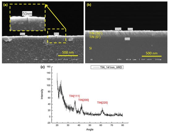
2.1. Sample Preparation

TiN and i-TiN thin layers were deposited on a Si substrate by using a radiofrequency (RF) magnetron sputter. The processing temperature of the substrate was 400 °C, and the starting pressure was 5 × 10⁻⁶ Torr. The RF source was maintained at 250 W under a flow of Ar (7 sccm) and N2 (5 sccm) air (237 K, 760 Torr).
Sample Series 1 comprised normally grown TiN layers of various thicknesses, deposited on a BK7 glass slide (25 × 25 × 1 mm3), whereas Sample Series 2 comprised TiN(43 nm)/i-TiN layers, deposited on an identical glass slide. The thicknesses of i-TiN layers were changed using various deposition times and by tilting the substrate 50° during the sputtering process. The TiN (Figure 1a) and TiN/i-TiN (Figure 1b) thin layers deposited on the Si substrate were visualized through scanning electron microscopy.
The i-TiN layer has a higher specific surface area to contact the target solution and enhance the sensitivity of refractive index measurements. The smallest thickness of the homogeneous i-TiN layer fabricated by the inclined deposition method was 1.4 mm. X-ray diffraction analysis (Figure 1c) revealed that the deposited TiN layer (141 nm thick) demonstrated various signal peaks of typical crystal surfaces.
Table 1 presents the charge carrier concentrations of samples measured by a Hall effect measurement system (Accent HL5500PC) with various thicknesses of deposited TiN thin layers. Typically, the bulk carrier density (BCD) is calculated from the sheet carrier density (SCD) data following the definition BCD = SCD / Δ h , where Δ h is the thickness of the sample thin film. The deposited TiN layer on the glass substrate could achieve the highest bulk and sheet carrier densities up to 1.91 × 1022 cm−3 and 8.77 × 1016 cm−2, respectively. Thus, the deposited TiN layer could resemble Si, whereby it could generate SPR under light illumination. The additional i-TiN layer slightly reduced the bulk and sheet carrier densities but enhanced the precision of data acquisition in subsequent SPR heterodyne phase interrogation measurements (Table 1).

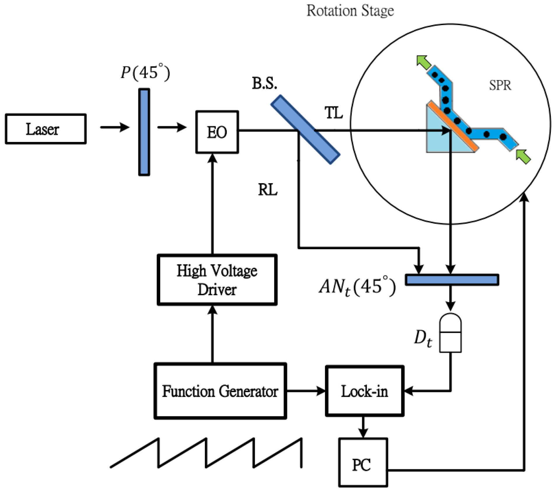
2.2. Experimental Setup

An SPR heterodyne phase interrogation system was constructed to detect the refractive index of a glucose solution flowing through a small liquid test cell (Figure 2). In the experimental setup, a polarizer defined the polarization of 1150 nm coherent light from a laser. The continuous polarized light was modulated into a jagged variation on illuminated intensity by an electro-optic (EO) modulator (ADP, NH4H2PO4, ConOptics) that was triggered by a function generator (DS345, Stanford Research System) and high-voltage driver (Model: 302, ConOptics). The beam splitter (BS) further divided the light into two light beams, namely test and reference light beams, with perpendicular propagation paths. The test beam illuminated the liquid test cell through a prism with the Kretschmann configuration [22,70]. Surface plasmons are only generated by illuminating P-polarized light in the deposited metal layer and should be affected by the refractive index of the covering test solution. The test glucose solutions of various concentrations can flow in the circular test flow cell (diameter, 20 mm; depth, 0.5 mm; volume, 0.157 mL), defined by an aluminum chamber and O-ring.
Both the reference beam and the output light from the testing unit also propagated through the analyzer, converted to an electrical test signal, and was sent to a lock-in amplifier. The reflectivity and locked-in phase difference were obtained by referencing the light-modulating electrical signal from the function generator and then translating it to the refractive index of the test solution.
In the experimental setup, the light intensity of the test beam measured using the detector can be expressed as
I t = | E t | 2 = 1 2 ( | r p | 2 + | r s | 2 2 + | r p | | r s | c o s ( ω t + ϕ p ϕ s ) )
where I r and I t are the reference and the test beam intensities, respectively, both of which have the oscillated term c o s ( ω t ) . ω is the light intensity modulation frequency defined by a function generator and EO modulator. The refraction coefficients of polarized P-wave ( | r p | ) and S-wave ( | r s | ) are the ratio of the reflected wave’s electric field complex amplitude to that of the incident wave. Therefore, the light intensity-related term | r p | | r s | and phase difference term ( Δ ϕ ) of P- and S-polarized light ( Δ ϕ = ϕ p ϕ s ) can be extracted through calculation with I r and I t by using the lock-in amplifier. Furthermore, only the electromagnetic wave with an electric field that lies on the incident plane can induce SPR in the Kretschmann configuration and | r s | ~ 1 . The square of the readout value from the lock-in amplifier is ( | r p | | r s | ) 2 , which is equal to the ratio of light reflected by the metal layer in experiments [44].

3. Results and Discussion

Analytical solutions of multilayer reflectivity were used to acquire with various wavelengths (Figure 3), reflectivities (Figure 4a,c), and phase differences (Figure 4b,d) for various light incident angles based on the Fresnel equation for multiple optical reflections and transmissions; light was illuminated from the glass substrate to a 46 nm TiN layer covered with glucose solutions of various refractive indexes [44]. Theoretical estimation of reflection coefficient ( r i j ) was acquired as inclined incident light illuminating from the i -th to j -th multilayers:
r i j = ( Z i q + Z j q ) ( Z i q + Z j q )
where q denotes the P- or S-wave. Z i P = ε i / k z i and Z i S = k z i . ε i is the dielectric constant of incident light for the i -th layer. k z i = k x 2 ε i k 0 2 = k 0 ε i ε 1 s i n 2 θ . k 0 and k x are the wavevector and its component in the x-direction, respectively. θ is the illuminating angle of incident light. The multiple transmissions and reflections of the three layers (glass/TiN/glucose solution) can be simplified to acquire the reflection coefficient:
r 123 = ( r 12 + r 23 e i 2 k z 2 d 2 ) ( 1 + r 12 r 23 e i 2 k z 2 d 2 )
The subscripts 1, 2, and 3 denote layers of glass, TiN, and glucose solution, respectively. d 2 is the thickness of the TiN layer. The reflection coefficients are both complex numbers for P- and S- polarized light and can be expressed as r p = | r p | e i ϕ p and r s = | r s | e i ϕ s , respectively.
The reflectivity with various wavelengths of oblique incident light at 49.7° for various concentrations of glucose solution [44] can be analytically resolved by the reflection coefficient above. The differences in reflectivity for various concentrations of glucose solution were not large for incident light wavelengths shorter than 850 nm. TiN is thus typically used to generate SPR with light longer than 850 nm [65,66]. With low chemical activity and strong mechanical hardness, deposited TiN layers [63,64,65,66,67,68,69] of nanostructures are good plasmonic materials with long-term stability.
The reflectivity (Figure 4a,c) and phase difference (Figure 4b,d) in calculations delivered similar results to those in experimental measurements (Figure 5 and Figure 6). The wavelength of light in the analytical calculations was 1150 nm. The theoretical calculations showed that the reflectivity (Figure 4c) and phase difference (Figure 4d) presented relatively large variations for incident light illuminating at 45°–65°. Due to the limitation of the experimental setup processed with a prism, the experimental results were only acquired with incident angles at 48°–52° without loss of generality. The refractive index estimation was based on the slope of the data curve with incident light at around 49.7°.
In the theoretical calculation (Figure 4) and experimental measurements (Figure 5), the relatively higher value of reflectivity and phase difference close to 49° indicated the critical angle of TIR in Kretschmann configuration, which resembled results presented in Figure 5 in the reference work [65]. As the incident light angle further increased, the TIR coupling and SPR generation quickly decreased and experienced a sharp dip in reflectivity, which is typically seen in many plasmonic ATR sensing applications. The relatively high reflectivity at the critical angle is usually not as apparent when using a thin, metal film such as with a SPR generator. However, the TiN thin film has low charge carrier concentrations and has a relatively apparent, high reflectivity at the critical angle and broader dip or valley, indicating SPR response [65].
In experimental measurements, the various concentrations of glucose solution presented slightly shifted patterns of reflectivity (Figure 5a) and phase differences (Figure 5b) concerning different light illumination angles. The reflectivity (Figure 5c) and phase difference (Figure 5d) for 49.7° incident light were acquired and presented a linear agreement with the known refractive indexes of the glucose solution.
As shown in Table 1, the 46 nm deposited TiN layer exhibited the highest bulk and sheet carrier densities. Experimental results in Figure 5c suggest that the sample with the 46 nm TiN layer presented relatively high reflectivity. The results of phase difference measurements (Figure 5d) also showed that samples with 46 nm TiN layers demonstrated relatively high precision and stability. Therefore, the sample with the 46 nm TiN layer was chosen as the base for an additional i-TiN layer.
The additional i-TiN layers of various thicknesses further enhanced the reflectivity (Figure 6a,c) and precision of the phase difference (Figure 6b,d) measurements of the refractive indexes of variously concentrated glucose solutions. The additional 1.4 nm i-TiN layer improved the performance of the base 46 nm normally deposited TiN layer. In order to acquire the detection limit or smallest refractive index unit (RIU) ( σ n ) resolvable in reflectivity and phase measurements, we followed the definitions of Nelson et al. [28] and our previous work [20,21,44] to consider the following quantity:
σ n = ( Δ n Δ ϕ ) σ ϕ
where Δ n / Δ ϕ is the local slope of the refractive index n versus phase ϕ curve, and σ ϕ is the finest resolution available, which is 0.01°, from the lock-in amplifier used in our experiments. The slopes Δ n / Δ ϕ of the phase measurements for a 46 nm TiN layer with and without an additional 1.4 nm i-TiN layer were 6.1 × 10⁻⁵ and 1.2 × 10⁻⁴, respectively. Therefore, the acquired refractive index detection limit for glucose solution in the phase mode increased to 6.1 × 10⁻⁷ RIU with the addition of a 1.4 nm i-TiN layer. This was better than the 1.2 × 10⁻⁶ RIU obtained with the 46 nm TiN layer (Figure 6b).
The experimental results showed that the phase difference data (Figure 5d and Figure 6b) had higher consistency than that in the reflectivity (Figure 5c and Figure 6a) concerning various refractive indexes. The modification with Equation (4) presented higher stability of acquired data in phase difference measurements. Addition of the i-TiN layer further decreased the detection limit. The Nelson’s modification of phase difference measurements and additional i-TiN layer in combination presented the lowest detection limit of 6.1 × 10⁻⁷ RIU in our measurements.
Experimental results presented that use of the SPR heterodyne phase interrogation system with low chemical activity and a reusable TiN layer was beneficial for refractive index detection in the liquid phase. The protruded nanorods can have a larger specific surface area to contact the target solution and further enhance the sensitivity of refractive index measurements in the SPR heterodyne phase interrogation system [20]. However, addition of an inclined-deposited TiN layer in the nanorod array reduced the carrier concentration. The increase of the i-TiN layer thickness gradually reduced the detection limit in measurements.
The TiN-based sensor also presented potential reusability in three repeated trials. Results for 5% glucose solution were highly similar among the three repeated experiments. The intervals after every run involved cleaning with acetone, methanol, and deionized water sequentially. The experimental data in reflectivity (Figure 7a) and phase (Figure 7b) measurements presented similar results in three experiment runs. The deposited TiN layer provided stability and was reusable in multiple processes of refractive index sensors. The typically used thin metal films (e.g., Ag or Au) for plasmonic applications are easily oxidized or peeled from the substrate, which makes them unsuitable for reuse or long-term storage. Thus, the high stability and reusability of the deposited TiN layer could increase the long-lasting durability of plasmonic refractive index sensors or measurements in future applications.

4. Conclusions

In this study, TiN with additional i-TiN thin layers was successfully deposited on a glass substrate by using the inclined deposition method. The bulk charge carrier densities of the deposited TiN layer with and without an additional i-TiN layer reached 1.28 × 10²² and 1.91 × 1022 cm−3, respectively. A home-built SPR heterodyne phase interrogation system was used for measuring the refractive index of glucose solutions. The experimental results presented good agreement with the Fresnel equation’s analytical solutions of multiple-layer reflectivity and phase differences. The refractive index of a liquid was resolved by using the SPR heterodyne phase interrogation method in the theoretical model. The detection limits of the sample solution using the 46 nm TiN layer with and without an additional 1.4 nm i-TiN layer were 6.1 × 10⁻⁷ and 1.2 × 10⁻⁶ RIU, respectively. The detection limit of the plasmonic ATR refractive index measurement using a TiN layer was lower than that using an Ag layer [44]. However, the reusability and low cost of the TiN layer provide high potential for use as practical plasmonic sensors for biosensing with potential long-term durability in future applications.

Author Contributions

R.-J.S., H.J.H., and C.-N.H. conceived and carried out the experiments. H.-P.C. designed the study. Y.-W.L., H.J.H., B.-H.L., and Y.-F.C.C. analyzed the data and wrote the manuscript. All authors have read and agreed to the published version of the manuscript.

Funding

This work was supported by the Ministry of Science and Technology, Taiwan (grant numbers: MOST 106-2112-M-019-0035-MY3 and MOST 108-2112-M-492-001) and University Research Grant of Universiti Brunei Darussalam (grant number: UBD/RSCH/1.9/FICBF(b)/2019/006).

Conflicts of Interest

The authors declare no conflict of interest.

References

  1. Kim, B.H.; Chang, I.S.; Gil, G.C.; Park, H.S.; Kim, H.J. Novel BOD (biological oxygen demand) sensor using mediator-less microbial fuel cell. Biotechnol. Lett. 2003, 25, 541–545. [Google Scholar] [CrossRef] [PubMed]
  2. Preininger, C.; Klimant, I.; Wolfbeis, O.S. Optical fiber sensor for biological oxygen demand. Anal. Chem. 1994, 66, 1841–1846. [Google Scholar] [CrossRef]
  3. Grönroos, A.; Kyllönen, H.; Korpijärvi, K.; Pirkonen, P.; Paavola, T.; Jokela, J.; Rintala, J. Ultrasound assisted method to increase soluble chemical oxygen demand (SCOD) of sewage sludge for digestion. Ultrason. Sonochem. 2005, 12, 115–120. [Google Scholar] [CrossRef] [PubMed]
  4. Zheng, Q.; Zhou, B.; Bai, J.; Li, L.; Jin, Z.; Zhang, J.; Li, J.; Liu, Y.; Cai, W.; Zhu, X. Self-organized TiO2 nanotube array sensor for the determination of chemical oxygen demand. Adv. Mater. 2008, 20, 1044–1049. [Google Scholar] [CrossRef]
  5. Sun, K.; Xia, N.; Zhao, L.; Liu, K.; Hou, W.; Liu, L. Aptasensors for the selective detection of alpha-synuclein oligomer by colorimetry, surface plasmon resonance and electrochemical impedance spectroscopy. Sens. Actuators B Chem. 2017, 245, 87–94. [Google Scholar] [CrossRef]
  6. Fischer, M.; Scholz-Böttcher, B.M. Microplastics analysis in environmental samples-recent pyrolysis-gas chromatography-mass spectrometry method improvements to increase the reliability of mass-related data. Anal. Methods 2019, 11, 2489–2497. [Google Scholar] [CrossRef]
  7. Nie, S.; Emory, S.R. Probing single molecules and single nanoparticles by surface-enhanced Raman scattering. Science 1997, 275, 1102–1106. [Google Scholar] [CrossRef]
  8. Kneipp, K.; Lemma, T.; Antunes, P.A.; Aroca, R. Single molecule detection using surface-enhanced Raman scattering (SERS). Phys. Rev. Lett. 1997, 78, 1667–1670. [Google Scholar] [CrossRef] [Green Version]
  9. Tseng, M.; Chang, C.M.; Cheng, B.H.; Wu, P.H.; Chung, K.S.; Hsiao, M.-K.; Huang, H.W.; Huang, D.-W.; Chiang, H.-P.; Leung, P.T.; et al. Multi-level surface enhanced Raman scattering using AgOx thin film. Opt. Express 2013, 21, 24460–24467. [Google Scholar] [CrossRef] [Green Version]
  10. Lin, W.-C.; Jen, H.-C.; Chen, C.-L.; Hwang, D.-F.; Chang, R.; Hwang, J.-S.; Chiang, H.-P. SERS study of tetrodotoxin (TTX) by using silver nanoparticle arrays. Plasmonics 2016, 4, 187–192. [Google Scholar] [CrossRef]
  11. Rodgers, P.J.; Amemiya, S. Cyclic voltammetry at micropipetelectrodes for the study of ion-transfer kinetics at liquid/liquid interfaces. Anal. Chem. 2007, 79, 9276–9285. [Google Scholar] [CrossRef] [PubMed]
  12. Yuhu, S.H.; Wang, Y.; Wang, X.; Xu, L.; Xiang, J.; Sun, W. Electrochemical detection of hydroquinone with a gold nanoparticle and graphene modified carbon ionic liquid electrode. Sens. Actuators B Chem. 2012, 168, 27–33. [Google Scholar]
  13. Roberts, J.G.; Sombers, L.A. Fast scan cyclic voltammetry: Chemical sensing in the brain and beyond. Anal. Chem. 2018, 90, 490–504. [Google Scholar] [CrossRef] [PubMed]
  14. Saiki, R.; Scharf, S.; Faloona, F.; Mullis, K.; Horn, G.; Erlich, H.; Arnheim, N. Enzymatic amplification of beta-globin genomic sequences and restriction site analysis for diagnosis of sickle cell anemia. Science 1985, 230, 1350–1354. [Google Scholar] [CrossRef] [PubMed]
  15. Zhang, Y.; Jiang, H.R. A review on continuous-flow microfluidic PCR in droplets: Advances, challenges and future. Anal. Chim. Acta 2016, 914, 7–16. [Google Scholar] [CrossRef] [Green Version]
  16. Cavanaugh, S.E.; Bathrick, A.S. Direct PCR amplification of forensic touch and other challenging DNA samples: A review. Forensic Sci. Int. Genet. 2018, 32, 40–49. [Google Scholar] [CrossRef]
  17. Gerislioglu, B.; Dong, L.; Ahmadivand, A.; Hu, H.; Nordlander, P.; Halas, N.J. Monolithic metal dimer-on-film structure: New plasmonic properties introduced by the underlying metal. Nano Lett. 2020, 20, 2087–2093. [Google Scholar] [CrossRef]
  18. Gerislioglu, B.; Ahuja, R.; Mishra, Y.K. Terahertz plasmonics: The rise of toroidal metadevices towards immune biosensing. Mater. Today 2020, 32, 108–130. [Google Scholar]
  19. Ahmadivand, A.; Gerislioglu, B.; Ramezani, Z.; Ghoreishi, S.A. Attomolar detection of low-molecular weight antibiotics using midinfrared-resonant toroidal plasmonic metachip technology. Phys. Rev. Appl. 2019, 12, 034018. [Google Scholar] [CrossRef]
  20. Chung, H.; Chen, C.-C.; Wu, P.C.; Tseng, M.L.; Lin, W.-C.; Chen, C.-W.; Chiang, H.-P. Enhanced sensitivity of surface plasmon resonance phase-interrogation biosensor by using oblique deposited silver nanorods. Nanoscale Res. Lett. 2014, 9, 476. [Google Scholar] [CrossRef] [Green Version]
  21. Peng, T.C.; Lin, W.C.; Chen, C.W.; Tsai, D.P.; Chiang, H.P. Enhanced sensitivity of surface plasmon resonance phase-interrogation biosensor by using silver nanoparticles. Plasmonics 2011, 6, 29–34. [Google Scholar] [CrossRef]
  22. Raether, H. Surface Plasmons on Smooth and Rough Surfaces and on Gratings; Springer: New York, NY, USA, 1988. [Google Scholar]
  23. Gryga, M.; Vala, D.; Kolejak, P.; Gembalova, L.; Ciprian, D.; Hlubina, P. One-dimensional photonic crystal for Bloch surface waves and radiation modes-based sensing. Opt. Mater. Express 2019, 9, 4009–4022. [Google Scholar] [CrossRef]
  24. Hlubina, P.; Lunackova, M.; Ciprian, D. Phase sensitive measurement of the wavelength dependence of the complex permittivity of a thin gold film using surface plasmon resonance. Opt. Mater. Express 2019, 9, 992–1001. [Google Scholar] [CrossRef] [Green Version]
  25. Luo, W.; Wang, R.; Li, H.; Kou, J.; Zeng, X.; Huang, H.; Hu, X.; Huang, W. Simultaneous measurement of refractive index and temperature for prism-based surface plasmon resonance sensors. Opt. Express 2019, 27, 576–589. [Google Scholar] [CrossRef] [PubMed]
  26. Abdulhalim, I.; Lakhtakia, A.; Lahav, A.; Zhang, F.; Xu, J. Porosity effect on surface plasmon resonance from metallic sculptured thin films. SPIE Opt. Photonics 2008, 7041, 70410C. [Google Scholar]
  27. Homola, J. Present and future of surface plasmon resonance biosensors. Anal. Bioanal. Chem. 2003, 377, 528–539. [Google Scholar] [CrossRef] [PubMed]
  28. Nelson, S.G.; Johnston, K.S.; Yee, S.S. High sensitivity surface plasmon resonace sensor based on phase detection. Sens. Actuators B Chem. 1996, 35, 187–191. [Google Scholar] [CrossRef]
  29. Naraoka, R.; Kajikawa, K. Phase detection of surface plasmon resonance using rotating analyzer method. Sens. Actuators B Chem. 2005, 107, 952–956. [Google Scholar] [CrossRef]
  30. Chiang, H.-P.; Yeh, H.-T.; Chen, C.-M.; Wu, J.-C.; Su, S.-Y.; Chang, R.; Wu, Y.-J.; Tsai, D.P.; Jen, S.U.; Leung, P.T. Surface plasmon resonance monitoring of temperature via phase measurement. Opt. Commun. 2004, 241, 409–418. [Google Scholar] [CrossRef]
  31. Chiang, H.-P.; Lin, J.-L.; Chang, R.; Su, S.-Y.; Leung, P.T. High-resolution angular measurement using surface-plasmon-resonance via phase interrogation at optimal incident wavelengths. Opt. Lett. 2005, 30, 2727–2729. [Google Scholar] [CrossRef] [Green Version]
  32. Barchiesi, D.; Lidgi-Guigui, N.; Chapelle, M.L.D.L. Functionalization layer influence on the sensitivity of surface plasmon resonance (SPR) biosensor. Opt. Commun. 2012, 285, 1619–1623. [Google Scholar] [CrossRef]
  33. Szunerits, S.; Shalabney, A.; Boukherroub, R.; Abdulhalim, I. Dielectric coated plasmonic interfaces: Their interest for sensitive sensing of analyte-ligand interactions. Rev. Anal. Chem. 2012, 31, 15–28. [Google Scholar] [CrossRef]
  34. Shalabney, A.; Abdulhalim, I. Figure of merit enhancement of surface plasmon resonance sensors in the spectral interrogation. Opt. Lett. 2012, 37, 1175. [Google Scholar] [CrossRef] [PubMed]
  35. Lahav, A.; Shalabney, A.; Abdulhalim, I. Surface plasmon resonance sensor with enhanced sensitivity using top nano dielectric layer. J. Nanophotonics 2009, 3, 031501. [Google Scholar] [CrossRef]
  36. Lahav, A.; Auslender, M.; Abdulhalim, I. Sensitivity enhancement of guided wave surface plasmon resonance sensors. Opt. Lett. 2008, 33, 2539–2541. [Google Scholar] [CrossRef]
  37. Faryad, M.; Lakhtakia, A. Surface plasmon–polariton wave propagation guided by a metal slab in a sculptured nematic thin film. J. Opt. A 2010, 12, 085102. [Google Scholar] [CrossRef] [Green Version]
  38. Shalabney, A.; Lakhtakia, A.; Abdulhalim, I.; Lahav, A.; Patzig, C.; Hazek, I.; Karabchevsky, A.; Rauschenbach, B.; Zhang, F.; Xub, J. Surface plasmon resonance from metallic columnar thin films. Photon. Nanostruct. Fundam. Appl. 2009, 7, 176–185. [Google Scholar] [CrossRef]
  39. Shalabney, A.; Abdulhalim, I. Electromagnetic fields distribution in multilayer thin film structures and the origin of sensitivity enhancement in surface plasmon resonance sensors. Sens. Actuators A Phys. 2010, 159, 24–32. [Google Scholar] [CrossRef]
  40. Shalabney, A.; Abdulhalim, I. Sensitivity enhancement methods for surface plasmon sensors. Laser Photonics Rev. 2011, 5, 571–606. [Google Scholar] [CrossRef]
  41. Shalabney, A.; Khare, C.; Rauschenbach, B.; Abdulhalim, I. Sensitivity of surface plasmon resonance sensors based on metallic columnar thin films in the spectral and angular interrogations. Sens. Actuators B Chem. 2011, 159, 201–212. [Google Scholar] [CrossRef]
  42. Abdulhalim, I. Plasmonic sensing using metallic nano-sculptured thin films. Small 2014, 10, 3499–3514. [Google Scholar] [CrossRef] [PubMed]
  43. Abdulhalim, I. Coupling configurations between extended surface electromagnetic waves and localized surface plasmons for ultrahigh field enhancement. Nanophotonics 2018, 7, 1891–1916. [Google Scholar] [CrossRef]
  44. Chiang, H.P.; Lin, J.L.; Chen, Z.W. High sensitivity surface plasmon resonance sensor based on phase interrogation at optimal incident wavelengths. Appl. Phys. Lett. 2006, 88, 141105. [Google Scholar] [CrossRef]
  45. Homola, J.; Yee, S.S.; Gauglitz, G. Surface plasmon resonance sensors: Review. Sens. Actuators B Chem. 1999, 54, 3–15. [Google Scholar] [CrossRef]
  46. Zhang, W.; Li, Q.; Qiu, M. A plasmon ruler based on nanoscale photothermal effect. Opt. Express 2013, 21, 172–181. [Google Scholar] [CrossRef]
  47. Lu, J.Y.; Nam, S.H.; Wilke, K.; Raza, A.; Lee, Y.E.; AlGhaferi, A.; Fang, N.X.; Zhang, T. Localized surface plasmon-enhanced ultrathin film broadband nanoporous absorbers. Adv. Opt. Mater. 2016, 4, 1255–1264. [Google Scholar] [CrossRef]
  48. Kumara, N.T.R.N.; Chou Chau, Y.-F.; Huang, J.-W.; Huang, H.J.; Lin, C.-T.; Chiang, H.-P. Plasmonic spectrum on 1D and 2D periodic arrays of rod-shape metal nanoparticle pairs with different core patterns for biosensor and solar cell applications. J. Opt. 2016, 18, 115003. [Google Scholar] [CrossRef]
  49. Chou Chau, Y.-F.; Chou Chao, C.-T.; Lim, C.M.; Huang, H.J.; Chiang, H.-P. Deploying tunable metal-shell/dielectric core nanorod arrays as the virtually perfect absorber in the near-infrared regime. ACS Omega 2018, 3, 7508–7516. [Google Scholar] [CrossRef] [Green Version]
  50. Elshorbagy, M.H.; Cuadrado, A.; Gonzalez, G.; Gonzalez, F.J.; Alda, J. Performance improvement of refractometric sensors through hybrid plasmonic-Fano resonances. J. Lightwave Technol. 2019, 37, 2905–2913. [Google Scholar] [CrossRef] [Green Version]
  51. Lin, W.-C.; Huang, S.-H.; Chen, C.-L.; Chen, C.-C.; Tsai, D.P.; Chiang, H.-P. Controlling SERS intensity by tuning the size and height of a silver nanoparticle array. Appl. Phys. A 2010, 101, 185–189. [Google Scholar] [CrossRef]
  52. Chang, R.; Chiang, H.-P.; Leung, P.T.; Tsai, D.P.; Tse, W.S. Nonlocal effects in the optical response of composite materials with metallic nanoparticles. Solid State Commun. 2005, 133, 315–320. [Google Scholar] [CrossRef]
  53. Chou Chau, Y.-F.; Wang, C.-K.; Shen, L.; Lim, C.M.; Chiang, H.-P.; Chou Chao, C.-T.; Huang, H.J.; Lin, C.-T.; Kumara, N.T.R.N.; Voo, N.Y. Simultaneous realization of high sensing sensitivity and tunability in plasmonic nanostructures arrays. Sci. Rep. 2017, 7, 16817. [Google Scholar] [CrossRef] [PubMed] [Green Version]
  54. Chou Chau, Y.-F.; Chou Chao, C.-T.; Huang, H.J.; Lim, R.C.; Chiang, H.-P. Tunable plasmonic effects arising from metal–dielectric nanorods. Appl. Opt. 2019, 58, 2530–2539. [Google Scholar] [CrossRef]
  55. Chou Chau, Y.-F.; Chou Chao, C.-T.; Huang, H.J.; Wang, Y.-C.; Chiang, H.-P.; Idris, M.N.S.M.; Masri, Z.; Lim, C.M. Strong and tunable plasmonic field coupling and enhancement generating from the protruded metal nanorods and dielectric cores. Results Phys. 2019, 13, 102290. [Google Scholar] [CrossRef]
  56. Chou Chau, Y.-F.; Chou Chao, C.-T.; Huang, H.J.; Anwar, U.; Lim, C.M.; Voo, N.Y.; Mahadi, A.H.; Kumara, N.T.R.N.; Chiang, H.-P. Plasmonic perfect absorber based on metal nanorod arrays connected with veins. Results Phys. 2019, 15, 102567. [Google Scholar] [CrossRef]
  57. Chou Chau, Y.-F.; Chen, K.-H.; Chiang, H.-P.; Lim, C.M.; Huang, H.J.; Lai, C.-H.; Kumara, N.T.R.N. Fabrication and characterization of a metallic–dielectric nanorod array by nanosphere lithography for plasmonic sensing application. Nanomaterials 2019, 9, 1691. [Google Scholar] [CrossRef] [Green Version]
  58. Chou Chau, Y.-F.; Chou Chao, C.-T.; Huang, H.J.; Kooh, M.R.R.; Kumara, N.T.R.N.; Lim, C.M.; Chiang, H.-P. Perfect dual-band absorber based on plasmonic effect with the cross-hair/nanorod combination. Nanomaterials 2020, 10, 493. [Google Scholar] [CrossRef] [PubMed] [Green Version]
  59. Chou Chau, Y.-F.; Chou Chao, C.-T.; Huang, H.J.; Kumara, N.T.R.N.; Lim, C.M.; Chiang, H.-P. Ultra-high refractive index sensing structure based on a metal-insulator-metal waveguide-coupled T-shape cavity with metal nanorod defects. Nanomaterials 2019, 9, 1433. [Google Scholar] [CrossRef] [Green Version]
  60. Chou Chau, Y.-F.; Syu, J.-Y.; Chou Chao, C.-T.; Chiang, H.-P.; Lim, C.M. Design of crossing metallic metasurface arrays based on high sensitivity of gap enhancement and transmittance shift for plasmonic sensing applications. J. Phys. D Appl. Phys. 2017, 50, 045105. [Google Scholar] [CrossRef]
  61. Wang, T.-J.; Hsu, K.-C.; Liu, Y.-C.; Lai, C.-H.; Chiang, H.-P. Nanostructured SERS substrates produced by nanosphere lithography and plastic deformation through direct peel-off on soft matter. J. Opt. 2016, 18, 055006. [Google Scholar] [CrossRef]
  62. Chou Chau, Y.-F.; Lim, C.M.; Lee, C.; Huang, H.J.; Lin, C.-T.; Kumara, N.T.R.N.; Yoong, V.N.; Chiang, H.-P. Tailoring surface plasmon resonance and dipole cavity plasmon modes of scattering cross section spectra on the single solid-gold/gold-shell nanorod. J. Appl. Phys. 2016, 120, 093110. [Google Scholar] [CrossRef]
  63. Naik, G.V.; Schroeder, J.L.; Ni, X.; Kildishev, A.V.; Sands, T.D.; Boltasseva, A. Titanium nitride as a plasmonic material for visible and near-infrared wavelengths. Opt. Mater. Express 2012, 2, 478–489. [Google Scholar] [CrossRef] [Green Version]
  64. Naik, G.V.; Kim, J.; Boltasseva, A. Oxides and nitrides as alternative plasmonic materials in the optical range. Opt. Mater. Express 2011, 1, 1090–1099. [Google Scholar] [CrossRef] [Green Version]
  65. Chen, N.C.; Lien, W.C.; Liu, C.R.; Huang, Y.L.; Lin, Y.R.; Chou, C.; Chang, S.Y.; Ho, C.W. Excitation of surface plasma wave at TiN/air interface in the Kretschmann geometry. J. Appl. Phys. 2011, 109, 043104. [Google Scholar] [CrossRef]
  66. Kumar, K.K.; Raole, P.M.; Rayjada, P.A.; Chauhan, N.L.; Mukherjee, S. Study of structure development of titanium nitride on inclined substrates. Surf. Coat. Technol. 2011, 205, S187–S191. [Google Scholar] [CrossRef]
  67. Wei, B.; Liang, H.; Qi, Z.; Zhang, D.; Shen, H.; Hu, W.; Wang, Z. Construction of 3D Si@Ti@TiN thin film arrays for aqueous symmetric supercapacitors. Chem. Commun. 2019, 55, 1402–1405. [Google Scholar] [CrossRef] [PubMed]
  68. Fang, S.; Shen, L.; Li, S.; Dou, H.; Zhang, X. Self-supported TiN nanorod array/carbon textile as a lithium host that induces dendrite-free lithium plating with high rates and long cycle life. J. Mater. Chem. A 2020, 8, 3293–3299. [Google Scholar] [CrossRef]
  69. Yu, L.; Liang, F.; Wang, L.; Chang, L.; Wang, F.; Li, N. Significantly improved cycling stability for electrochemical hydrogen storage in Ti1.4V0.6Ni alloy with TiN. Mater. Res. Bull. 2019, 118, 110509. [Google Scholar] [CrossRef]
  70. Viarbitskaya, S.J.; Arocas, J.; Heintz, O.; Colas-Des-Francs, G.; Rusakov, D.; Koch, U.; Leuthold, J.; Markey, L.; Dereux, A.; Weeber, J.-C. Correlation between electrical direct current resistivity and plasmonic properties of CMOS compatible titanium nitride thin films. Opt. Express 2018, 26, 9813–9821. [Google Scholar] [CrossRef] [PubMed]
  71. Zakomirnyi, V.I.; Rasskazov, I.L.; Gerasimov, V.S.; Ershov, A.E.; Polyutov, S.P.; Karpov, S.V.; Ågren, H. Titanium nitride nanoparticles as an alternative platform for plasmonic waveguides in the visible and telecommunication wavelength ranges. Photon. Nanostruct. Fundam. Appl. 2018, 30, 50–56. [Google Scholar] [CrossRef]
  72. Patskovsky, S.; Vallieres, M.; Maisonneuve, M.; Song, I.-H.; Meunier, M.; Kabashin, A.V. Designing efficient zero calibration point for phase sensitive surface plasmon resonance biosensing. Opt. Express 2009, 17, 2255. [Google Scholar] [CrossRef] [PubMed]
  73. Watad, I.; Abdulhalim, I. Spectropolarimetric surface plasmon resonance sensor and the selection of the best polarimetric function. IEEE J. Sel. Top. Quantum Electron. 2017, 23, 4600609. [Google Scholar] [CrossRef]
  74. Watad, I.; Abdulhalim, I. Comparative study between polarimetric and intensity based surface plasmon resonance sensors in the spectral mode. Appl. Opt. 2017, 56, 7549–7558. [Google Scholar] [CrossRef] [PubMed]
  75. Watad, I.; Abdulhalim, I. Phase-shifted polarimetric surface plasmon resonance sensor using a liquid crystal retarder and a diverging beam. Opt. Lett. 2019, 44, 1607–1610. [Google Scholar] [CrossRef] [PubMed]
  76. Watad, I.; Abuleil, M.; Abdulhalim, I. Spectro-ellipsometric surface plasmon resonance sensor using a liquid crystal achromatic waveplate. IEEE Photonics Technol. Lett. 2020, 32, 550–553. [Google Scholar] [CrossRef]
  77. Chen, C.; Wang, Z.; Wu, K.; Chong, H.; Xu, Z.; Ye, H. ITO–TiN–ITO sandwiches for near-infrared plasmonic materials. ACS Appl. Mater. Interfaces 2018, 10, 14886–14893. [Google Scholar] [CrossRef]
Figure 1. Scanning electron microscopy images of the TiN layer deposited on a Si substrate at various deposition angles: (a) 0° (50 nm) and (b) 0° (43 nm)/50° (83 nm). (c) X-ray diffraction measurement of deposited TiN (141 nm) on the Si substrate.
Nanomaterials 10 01325 g001
Figure 2. Schematic of the experimental setup in the Kretschmann configuration for refractive index measurements. P: polarizer, BS: beam splitter, AN: analyzer, D: detector, TL: test light, RL: reference light.
Nanomaterials 10 01325 g002
Figure 3. Numerical reflectivity calculations at various wavelengths of 49.7° oblique incident light for various glucose solution concentrations. The thickness of the deposited TiN layer is 46 nm.
Nanomaterials 10 01325 g003
Figure 4. Numerical calculations of (a,c) reflectivity and (b,d) phase differences with various incident angles of 1150 nm incident light for various concentrations of glucose solution. The thickness of the deposited TiN layer is 46 nm.
Nanomaterials 10 01325 g004
Figure 5. (a) Reflectivity and (b) phase differences with various incident angles for various concentrations of glucose solution. The thickness of the deposited TiN layer is 46 nm. (c) Reflectivity and (d) phase for various refractive indexes (real part) of glucose solution using samples with various TiN layer thickness.
Nanomaterials 10 01325 g005
Figure 6. Dependence of (a) reflectivity and (b) phase on the various refractive indexes (real part) of glucose solutions on the various inclined deposition lengths of 46 nm of TiN layers deposited on glass. Dependence of detection limit of (c) reflectivity and (d) phase on the various thicknesses of additional TiN layers.
Nanomaterials 10 01325 g006
Figure 7. Reusability testing in three runs for (a) reflectivity and (b) phase measurements.
Nanomaterials 10 01325 g007
Table 1. Charge carrier concentrations of samples with various deposited thicknesses of the TiN thin layer. The error of the measurement is smaller than 1%.
Bulk Carrier Density (1/cm3)Sheet Carrier Density (1/cm2)
Glass/TiN (46 nm)1.91 × 10228.77 × 1016
Glass/TiN (50 nm)1.45 × 10217.22 × 1015
Glass/TiN (54.5 nm)3.32 × 10211.81 × 1016
Glass/TiN (46 nm)/Inc. TiN (1.4 nm)1.28 × 10225.87 × 1016
Glass/TiN (46 nm)/Inc. TiN (4.1 nm)2.10 × 10219.64 × 1015
Glass/TiN (46 nm)/Inc. TiN (6.9 nm)1.12 × 10215.13 × 1015

