
Fabrication of Graphene Based Durable Intelligent Personal Protective Clothing for Conventional and Non-Conventional Chemical Threats

 , , and
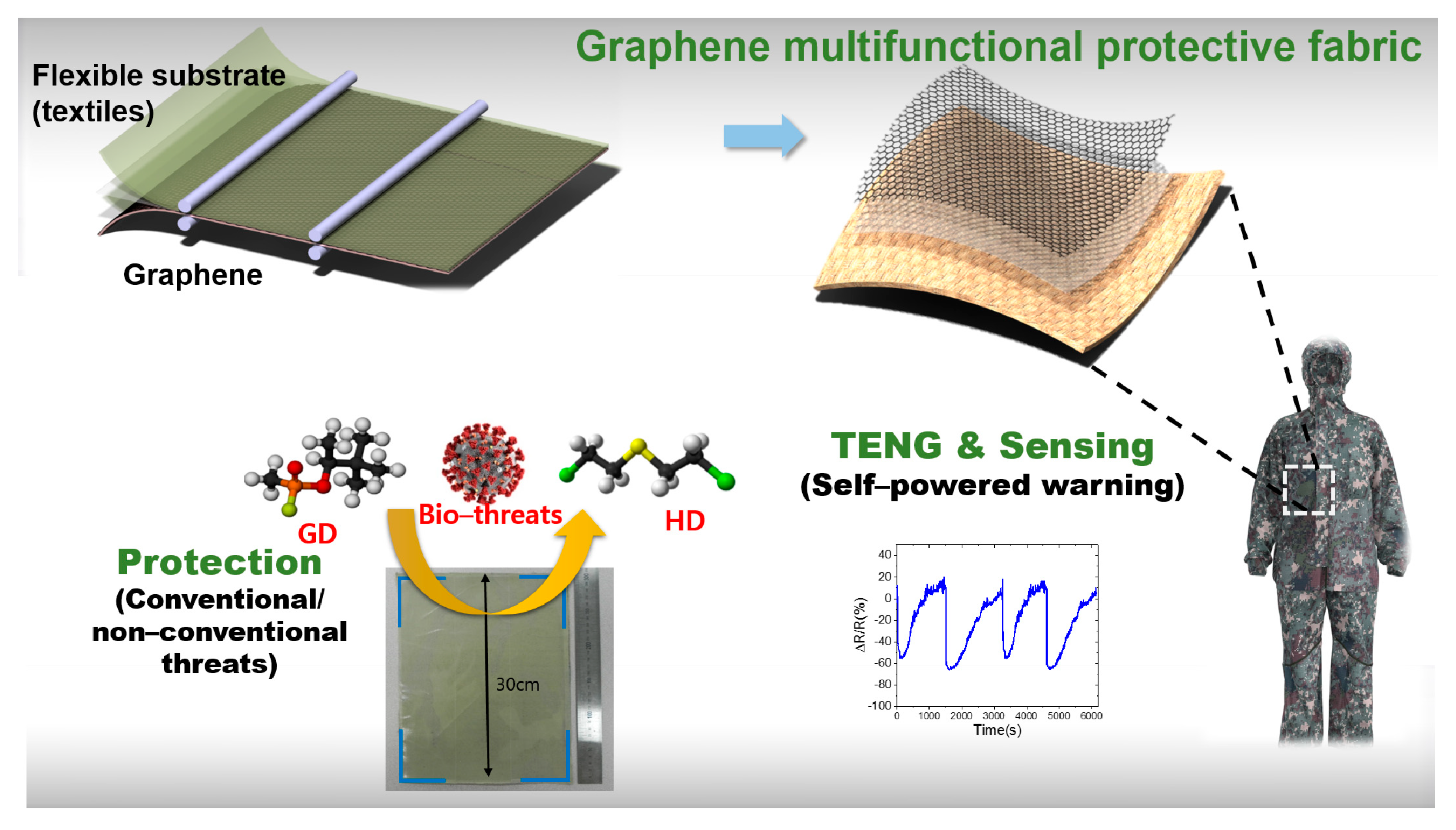
Abstract
:1. Introduction
2. Materials and Methods
2.1. CVD Graphene Growth
2.2. Fabrication of Graphene E-Fabric for Multifucitonal Protective Clothing
2.3. Characterization of Graphene E-Fabric
2.4. Fabrication and Characterization of Graphene E-Fabric Based TENG and Chemical Sensors
2.5. Theoretical Study Details
3. Results
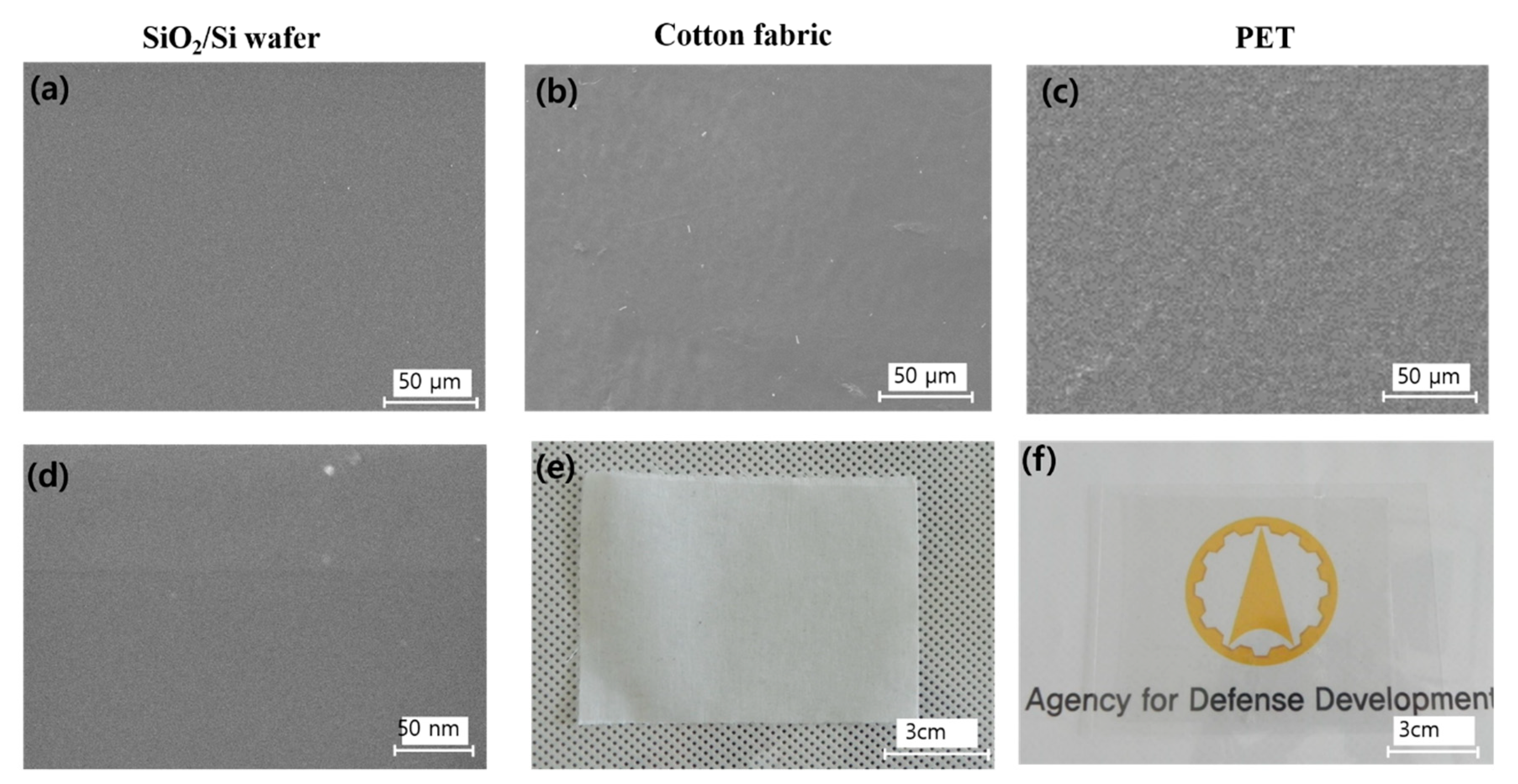
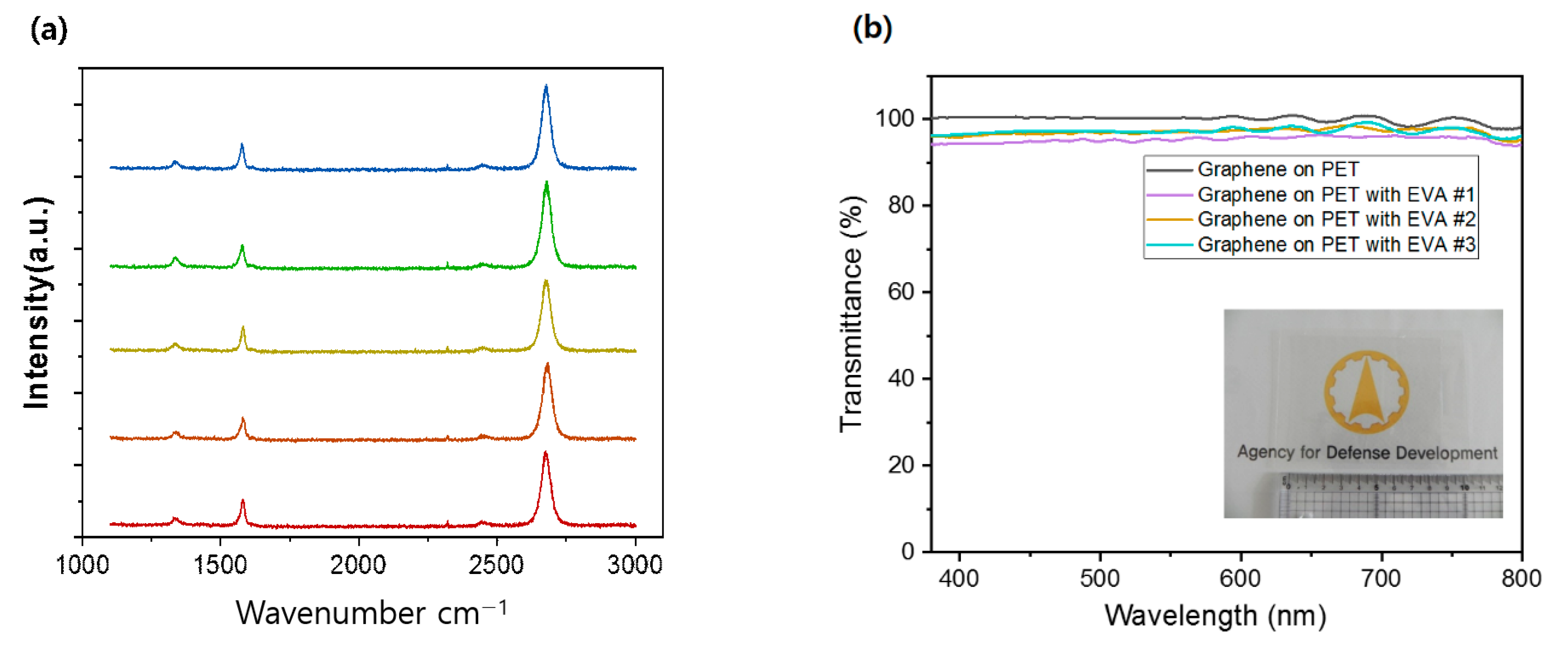
3.1. Structural Properties of Graphene E-Fabric
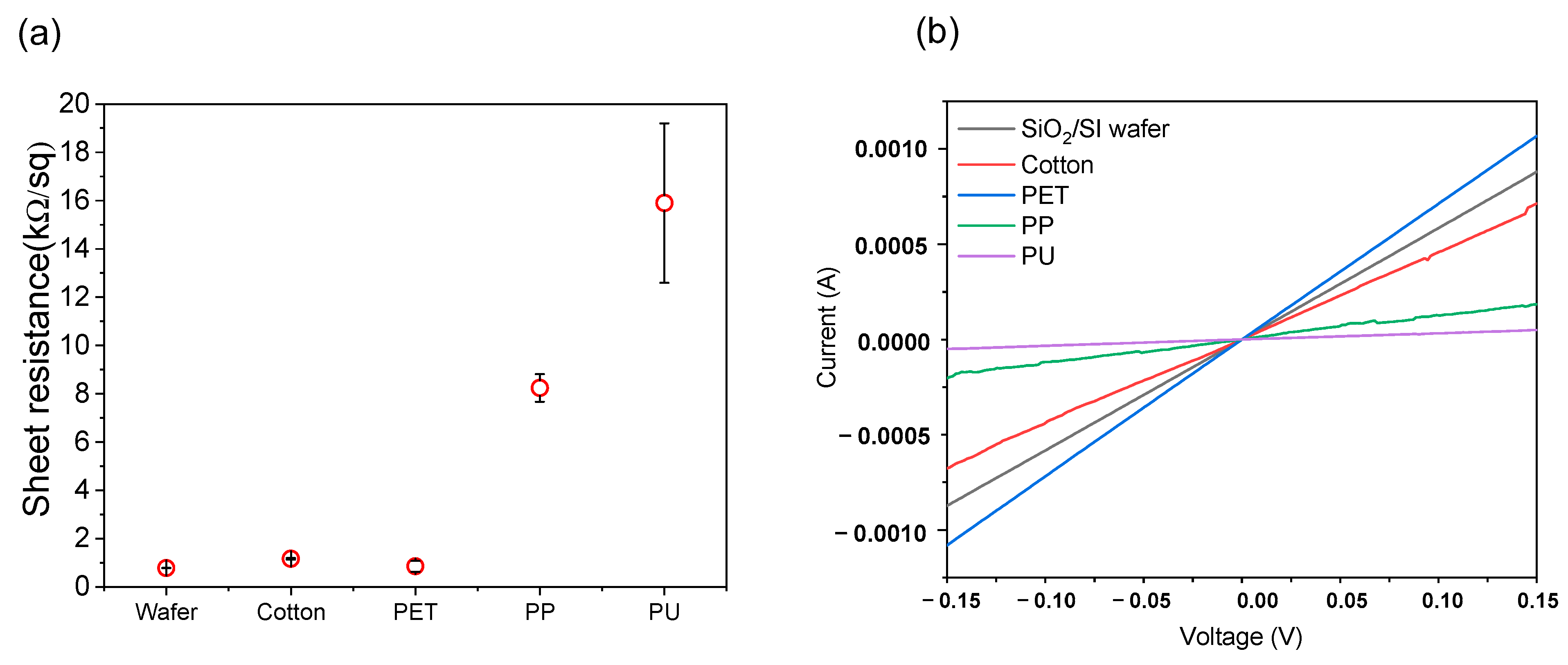
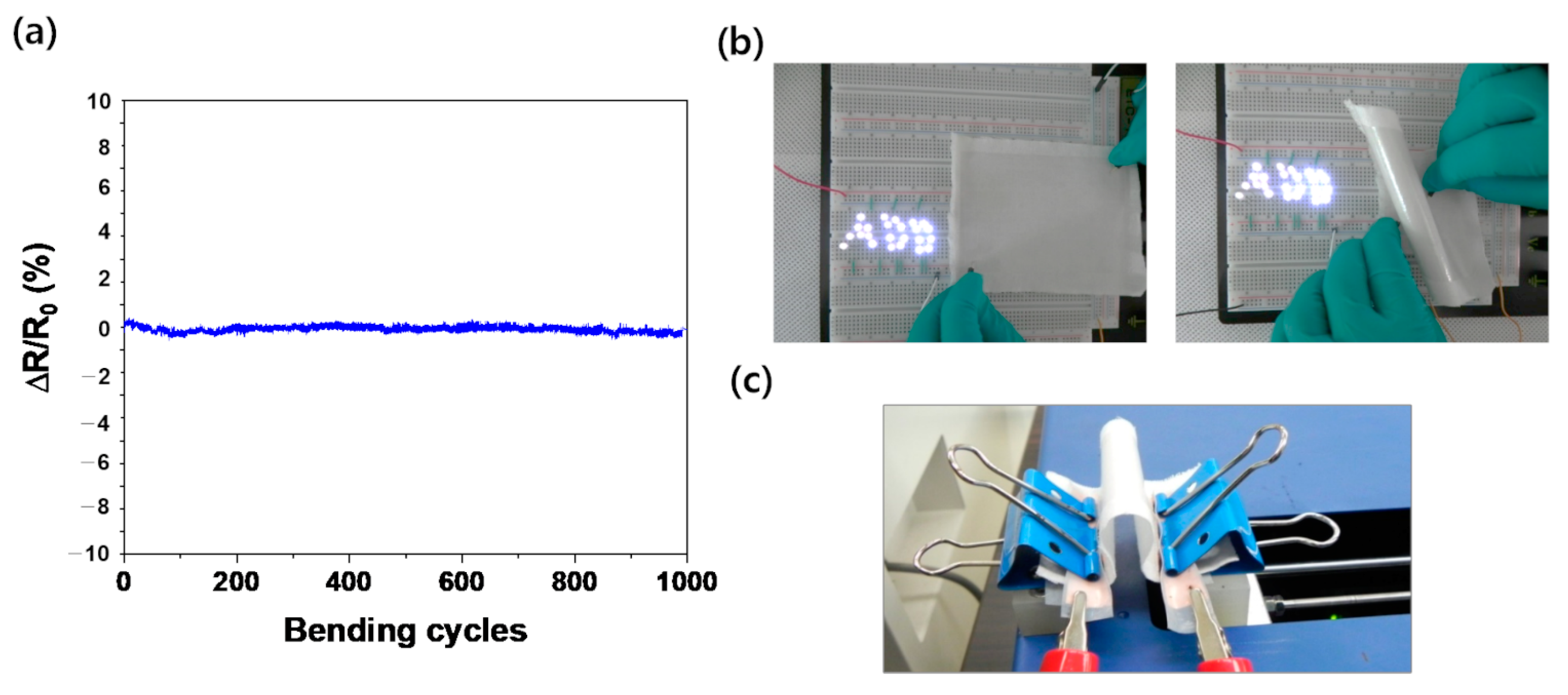
3.2. Electrical Properties of Graphene E-Fabric
4. Discussion
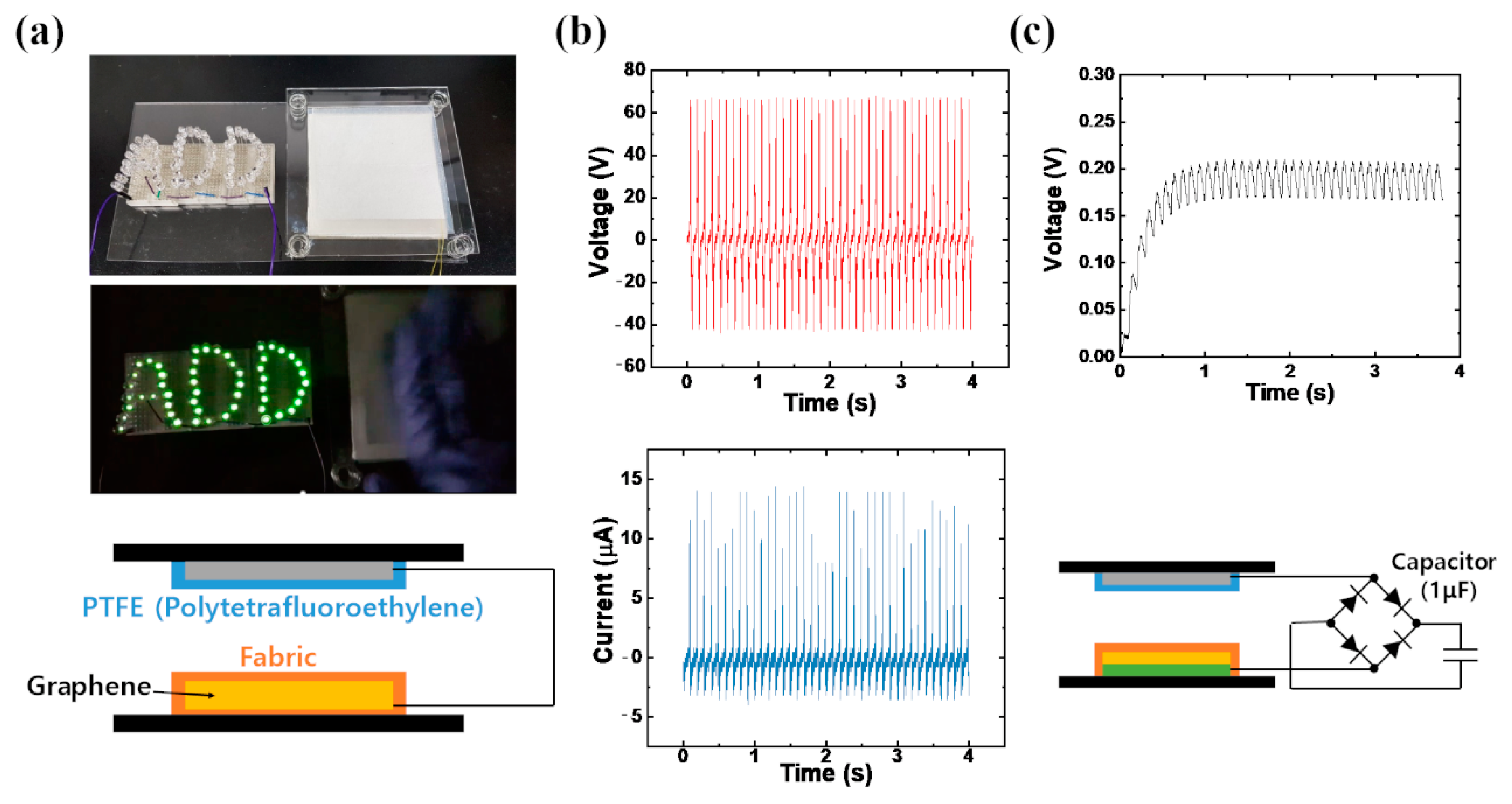
4.1. Graphene E-Fabric Based Triboelectric Nanogenerator for Intelligent Protective Clothing
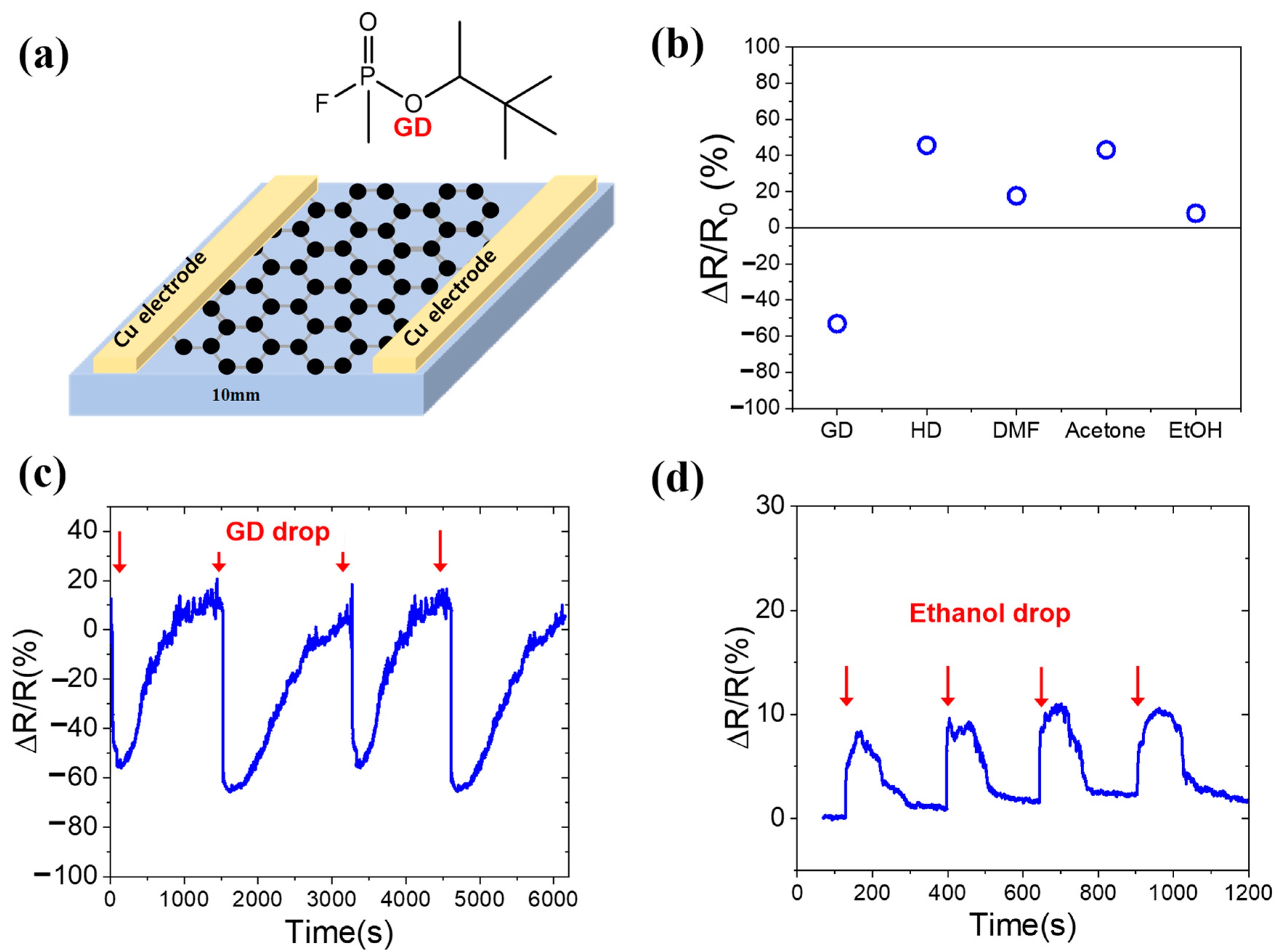
4.2. Graphene E-Fabric Based Wearable Chemical Sensor for Intelligent Protective Clothing
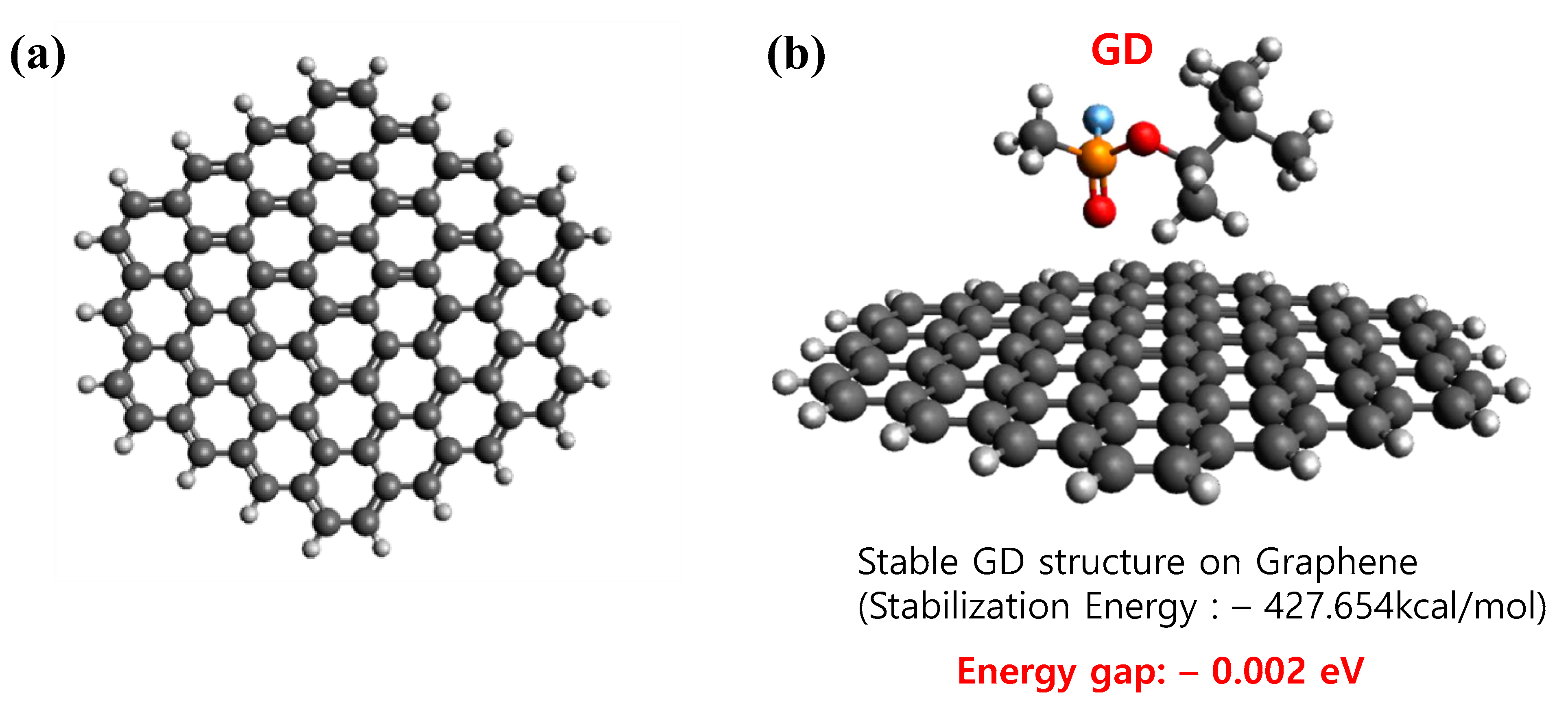
4.3. DFT Calculations Wearable E-Textile Chemical Sensor Based on Transferred Graphene
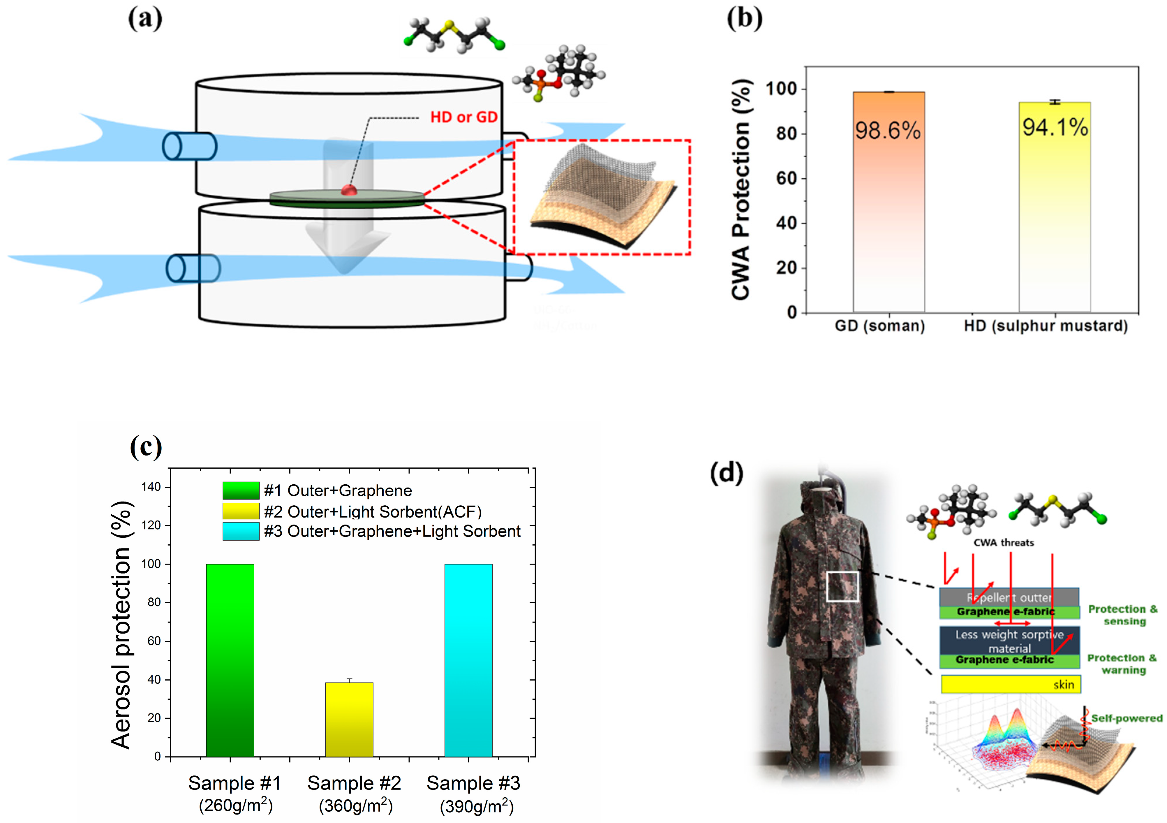
4.4. Protection of Graphene Intelligent Protective Clothing against CWAs, Biological and Radiological Threats
5. Conclusions
Supplementary Materials
Author Contributions
Funding
Institutional Review Board Statement
Informed Consent Statement
Data Availability Statement
Acknowledgments
Conflicts of Interest
References
- Kang, J.-S.; Seo, H.-K.; Park, H.-B.; Ryu, S.G.; Park, S.-H. A Study on the Design Concept for NBC Clothing. J. Korea Inst. Mil. Sci. Technol. 2012, 15, 193–200. [Google Scholar] [CrossRef] [Green Version]
- LaTourrette, T.; Peterson, D.J.; Bartis, J.T.; Jackson, B.A.; Houser, A. Protecting Emergency Responders Volume 2; Community Views of Safety and Health Risks and Personal Protection Needs, 1st ed.; RAND Corporation: Santa Monica, CA, USA, 2003. [Google Scholar]
- Bhattacharjee, S.; Joshi, R.; Chughtai, A.A.; Macintyre, C.R. Graphene Modified Multifunctional Personal Protective Clothing. Adv. Mater. Interfaces 2019, 6, 1900622. [Google Scholar] [CrossRef] [Green Version]
- Geim, A.K.; Novoselov, K.S. The rise of graphene. Nat. Mater. 2007, 6, 183–191. [Google Scholar] [CrossRef]
- Liu, Z.; Lau, S.P.; Yan, F. Functionalized graphene and other two-dimensional materials for photovoltaic devices: Device design and processing. Chem. Soc. Rev. 2015, 44, 5638–5679. [Google Scholar] [CrossRef]
- Xia, F.; Mueller, T.; Lin, Y.-m.; Valdes-Garcia, A.; Avouris, P. Ultrafast graphene photodetector. Nat. Nanotechnol. 2009, 4, 839–843. [Google Scholar] [CrossRef] [PubMed] [Green Version]
- Berger, C.; Song, Z.; Li, T.; Li, X.; Ogbazghi, A.Y.; Feng, R.; Dai, Z.; Marchenkov, A.N.; Conrad, E.H.; First, P.N.; et al. Ultrathin Epitaxial Graphite: 2D Electron Gas Properties and a Route toward Graphene-based Nanoelectronics. J. Phys. Chem. B 2004, 108, 19912–19916. [Google Scholar] [CrossRef] [Green Version]
- Hass, J.; Feng, R.; Li, T.; Li, X.; Zong, Z.; Heer, W.A.D.; First, P.N.; Conrad, E.H.; Jeffrey, C.A.; Berger, C. Highly ordered graphene for two dimensional electronics. Appl. Phys. Lett. 2006, 89, 143106. [Google Scholar] [CrossRef] [Green Version]
- Liu, M.; Zhang, R.; Chen, W. Graphene-Supported Nanoelectrocatalysts for Fuel Cells: Synthesis, Properties, and Applications. Chem. Rev. 2014, 114, 5117–5160. [Google Scholar] [CrossRef]
- Wu, Z.-S.; Feng, X.; Cheng, H.-M. Recent advances in graphene-based planar micro-supercapacitors for on-chip energy storage. Natl. Sci. Rev. 2013, 1, 277–292. [Google Scholar] [CrossRef] [Green Version]
- Ghosh, S.; Calizo, I.; Teweldebrhan, D.; Pokatilov, E.P.; Nika, D.L.; Balandin, A.A.; Bao, W.; Miao, F.; Lau, C.N. Extremely high thermal conductivity of graphene: Prospects for thermal management applications in nanoelectronic circuits. Appl. Phys. Lett. 2008, 92, 151911. [Google Scholar] [CrossRef]
- Liu, Y.; Dong, X.; Chen, P. Biological and chemical sensors based on graphene materials. Chem. Soc. Rev. 2012, 41, 2283–2307. [Google Scholar] [CrossRef]
- Mao, H.Y.; Laurent, S.; Chen, W.; Akhavan, O.; Imani, M.; Ashkarran, A.A.; Mahmoudi, M. Graphene: Promises, Facts, Opportunities, and Challenges in Nanomedicine. Chem. Rev. 2013, 113, 3407–3424. [Google Scholar] [CrossRef]
- Fu, J.; Qiao, Y.; Song, H.; Xu, Z.; Tu, J.; Ba, L.; Lu, Z. Advanced transferring of large-area freestanding graphene films by using fullerenes. Nanotechnology 2019, 30, 26LT01. [Google Scholar] [CrossRef]
- Huang, X.; Qi, X.; Boey, F.; Zhang, H. Graphene-based composites. Chem. Soc. Rev. 2012, 41, 666–686. [Google Scholar] [CrossRef] [PubMed]
- Stankovich, S.; Dikin, D.A.; Dommett, G.H.B.; Kohlhaas, K.M.; Zimney, E.J.; Stach, E.A.; Piner, R.D.; Nguyen, S.T.; Ruoff, R.S. Graphene-based composite materials. Nature 2006, 442, 282–286. [Google Scholar] [CrossRef] [PubMed]
- Zhu, Y.; Ji, H.; Cheng, H.M.; Ruoff, R.S. Mass Production and Industrial Applications of Graphene Materials. Natl. Sci. Rev. 2017, 5, 90. [Google Scholar] [CrossRef] [Green Version]
- de la Rosa, C.J.L.; Lindvall, N.; Cole, M.T.; Nam, Y.; Löffler, M.; Olsson, E.; Yurgens, A. Frame Assisted H2O Electrolysis Induced H2 Bubbling Transfer of Large Area Graphene Grown by Chemical Vapor Deposition on Cu. Appl. Phys. Lett. 2013, 102, 022101. [Google Scholar] [CrossRef] [Green Version]
- van der Laan, T.; Kumar, S.; Ostrikov, K. Water-mediated and instantaneous transfer of graphene grown at 220 °C enabled by a plasma. Nanoscale 2015, 7, 20564–20570. [Google Scholar] [CrossRef] [PubMed] [Green Version]
- Chandrashekar, B.N.; Smitha, A.S.; Wu, Y.; Cai, N.; Li, Y.; Huang, Z.; Wang, W.; Shi, R.; Wang, J.; Liu, S.; et al. A Universal Stamping Method of Graphene Transfer for Conducting Flexible and Transparent Polymers. Sci. Rep. 2019, 9, 3999. [Google Scholar] [CrossRef] [Green Version]
- Yang, S.-J.; Choi, S.; Odongo Ngome, F.O.; Kim, K.-J.; Choi, S.-Y.; Kim, C.-J. All-Dry Transfer of Graphene Film by van der Waals Interactions. Nano Lett. 2019, 19, 3590–3596. [Google Scholar] [CrossRef]
- Huang, S.; Dakhchoune, M.; Luo, W.; Oveisi, E.; He, G.; Rezaei, M.; Zhao, J.; Alexander, D.T.L.; Züttel, A.; Strano, M.S.; et al. Single-layer graphene membranes by crack-free transfer for gas mixture separation. Nat. Commun. 2018, 9, 2632. [Google Scholar] [CrossRef] [PubMed]
- Shivayogimath, A.; Whelan, P.R.; Mackenzie, D.M.A.; Luo, B.; Huang, D.; Luo, D.; Wang, M.; Gammelgaard, L.; Shi, H.; Ruoff, R.S.; et al. Do-It-Yourself Transfer of Large-Area Graphene Using an Office Laminator and Water. Chem. Mater. 2019, 31, 2328–2336. [Google Scholar] [CrossRef] [Green Version]
- Qing, F.; Zhang, Y.; Niu, Y.; Stehle, R.; Chen, Y.; Li, X. Towards large-scale graphene transfer. Nanoscale 2020, 12, 10890–10911. [Google Scholar] [CrossRef]
- Sun, H.; Chen, D.; Wu, Y.; Yuan, Q.; Guo, L.; Dai, D.; Xu, Y.; Zhao, P.; Jiang, N.; Lin, C.-T. High quality graphene films with a clean surface prepared by an UV/ozone assisted transfer process. J. Mater. Chem. C 2017, 5, 1880–1884. [Google Scholar] [CrossRef]
- Kim, J.; Sakakita, H.; Itagaki, H. Low-Temperature Graphene Growth by Forced Convection of Plasma-Excited Radicals. Nano Lett. 2019, 19, 739–746. [Google Scholar] [CrossRef]
- Wu, T.; Shen, H.; Sun, L.; You, J.; Yue, Z. Three step fabrication of graphene at low temperature by remote plasma enhanced chemical vapor deposition. RSC Adv. 2013, 3, 9544–9549. [Google Scholar] [CrossRef]
- Chandrashekar, B.N.; Deng, B.; Smitha, A.S.; Chen, Y.; Tan, C.; Zhang, H.; Peng, H.; Liu, Z. Roll-to-Roll Green Transfer of CVD Graphene onto Plastic for a Transparent and Flexible Triboelectric Nanogenerator. Adv. Mater. 2015, 27, 5210–5216. [Google Scholar] [CrossRef] [PubMed]
- Lu, T.; Chen, Q. A simple method of identifying π orbitals for non-planar systems and a protocol of studying π electronic structure. Theor. Chem. Acc. 2020, 139, 25. [Google Scholar] [CrossRef]
- Test Operations Procedure (TOP) 8-2-501, Permeation and Penetration of Air-Permeable, Semipermeable, and Impermeable Materials with Chemical Agents or Simulants (Swatch Testing); Final Report; AD-A-322329/4/XAB; TRN: 71470091 United States TRN: 71470091 GRA English; Dugway Proving Ground: Dugway, UT, USA, 1997.


Publisher’s Note: MDPI stays neutral with regard to jurisdictional claims in published maps and institutional affiliations. |
© 2021 by the authors. Licensee MDPI, Basel, Switzerland. This article is an open access article distributed under the terms and conditions of the Creative Commons Attribution (CC BY) license (https://creativecommons.org/licenses/by/4.0/).
Share and Cite
Jin, Y.; Ka, D.; Jang, S.; Heo, D.; Seo, J.A.; Jung, H.; Jeong, K.; Lee, S. Fabrication of Graphene Based Durable Intelligent Personal Protective Clothing for Conventional and Non-Conventional Chemical Threats. Nanomaterials 2021, 11, 940. https://0-doi-org.brum.beds.ac.uk/10.3390/nano11040940
Jin Y, Ka D, Jang S, Heo D, Seo JA, Jung H, Jeong K, Lee S. Fabrication of Graphene Based Durable Intelligent Personal Protective Clothing for Conventional and Non-Conventional Chemical Threats. Nanomaterials. 2021; 11(4):940. https://0-doi-org.brum.beds.ac.uk/10.3390/nano11040940
Chicago/Turabian StyleJin, Youngho, Dongwon Ka, Seongon Jang, Deokjae Heo, Jin Ah Seo, Hyunsook Jung, Keunhong Jeong, and Sangmin Lee. 2021. "Fabrication of Graphene Based Durable Intelligent Personal Protective Clothing for Conventional and Non-Conventional Chemical Threats" Nanomaterials 11, no. 4: 940. https://0-doi-org.brum.beds.ac.uk/10.3390/nano11040940